Embed Size (px)
Citation preview
Pipe Piece Family Manufacturing
U.S. DEPARTMENT OF TRANSPORTATIONMaritime Administrationin cooperation withTodd Pacific Shipyards Corporation
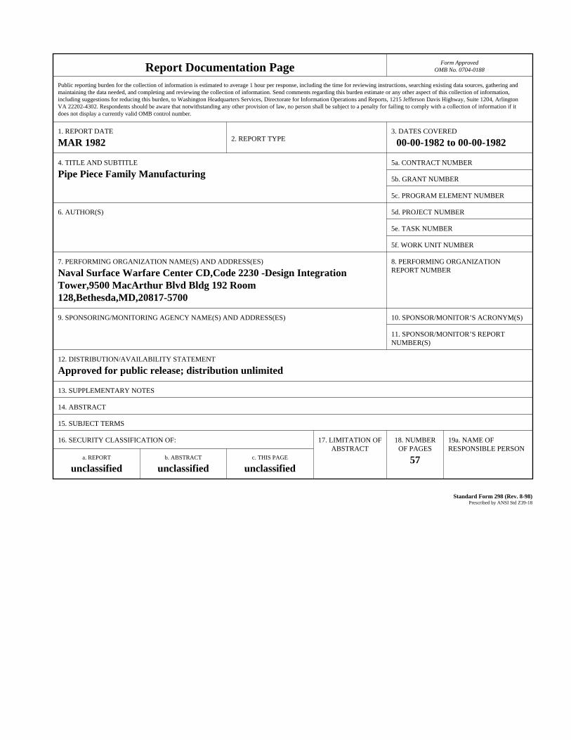
Report Documentation Page Form ApprovedOMB No. 0704-0188
Public reporting burden for the collection of information is estimated to average 1 hour per response, including the time for reviewing instructions, searching existing data sources, gathering andmaintaining the data needed, and completing and reviewing the collection of information. Send comments regarding this burden estimate or any other aspect of this collection of information,including suggestions for reducing this burden, to Washington Headquarters Services, Directorate for Information Operations and Reports, 1215 Jefferson Davis Highway, Suite 1204, ArlingtonVA 22202-4302. Respondents should be aware that notwithstanding any other provision of law, no person shall be subject to a penalty for failing to comply with a collection of information if itdoes not display a currently valid OMB control number.
1. REPORT DATE MAR 1982 2. REPORT TYPE
3. DATES COVERED 00-00-1982 to 00-00-1982
4. TITLE AND SUBTITLE Pipe Piece Family Manufacturing
5a. CONTRACT NUMBER
5b. GRANT NUMBER
5c. PROGRAM ELEMENT NUMBER
6. AUTHOR(S) 5d. PROJECT NUMBER
5e. TASK NUMBER
5f. WORK UNIT NUMBER
7. PERFORMING ORGANIZATION NAME(S) AND ADDRESS(ES) Naval Surface Warfare Center CD,Code 2230 -Design IntegrationTower,9500 MacArthur Blvd Bldg 192 Room 128,Bethesda,MD,20817-5700
8. PERFORMING ORGANIZATIONREPORT NUMBER
9. SPONSORING/MONITORING AGENCY NAME(S) AND ADDRESS(ES) 10. SPONSOR/MONITOR’S ACRONYM(S)
11. SPONSOR/MONITOR’S REPORT NUMBER(S)
12. DISTRIBUTION/AVAILABILITY STATEMENT Approved for public release; distribution unlimited
13. SUPPLEMENTARY NOTES
14. ABSTRACT
15. SUBJECT TERMS
16. SECURITY CLASSIFICATION OF: 17. LIMITATION OF ABSTRACT
18. NUMBEROF PAGES
57
19a. NAME OFRESPONSIBLE PERSON
a. REPORT unclassified
b. ABSTRACT unclassified
c. THIS PAGE unclassified
Standard Form 298 (Rev. 8-98) Prescribed by ANSI Std Z39-18
FOREWORD
Typically, large numbers of pipe pieces of many varieties in mixed quantitiesare required for a ship. Competitive shipbuilders have proven that productivityof the overall shipbuilding process increases when pipe pieces, regardless ofvarieties and quantities, are produced just-in-time to support assembly workerswho perform zone outfitting. In other words, a pipe shop’s contribution tooverall shipbuilding productivity is the only meaningful way to regard its perfor-mance.
Pipe-piece Family Manufacturing (PPFM) as described herein, is anotherform of Group Technology (GT) successfully applied by Ishikawajima-HarimaHeavy Industries Co., Ltd. of Japan. The substance was obtained mostly fromstudy of preparations for and operation of the very efficient pipe shop in IHI’sKure Shipyard which is manually operated and out produces automated shopselsewhere.
How well a pipe shop performs is determined by planners. Thus, necessarily is a discipline for the people who create design details and who per-form material definition. PPFM includes material control in procurement and inprocess until pipe pieces are painted and palletized to anticipate assembly workfor specific zones at specific times.
PPFM is a comprehensive methodology which simplifies the manufacture ofanything required in mixed varieties and quantities, e.g., vent-duct pieces as wellas pipe pieces. The planning and scheduling which has to be done is more com-plicated than that for traditional, less productive system-oriented methods.
No small reason for the development of PPFM and its effective application bycompetitive shipbuilders, is the presence of pipe-shop managers, deputymanagers and field engineers who have college or equivalent educations and whohave experience in other shipbuilding functions. They are, for example, able toapply statistical control for analytically and constantly improving pipe-shopmethods consistent with the competitive need to constantly improve the entireshipbuilding process.
PPFM is highly organized work. Statistical control is a way to constantly im-prove design details and work methods. Per Dr. W.E. Deming, known as thefather of productivity in Japan, “Gain is accomplished by changes in the systemeffected by management helping peopIe to work smarter, not harder. ”
ACKNOWLEDGEMENTS
L.D. Chirillo Associates, Bellevue, Washington produced this book for ToddPacific Shipyards Corporation, Los Angeles Division.
The book was developed in three stages. M. Kasama, International Division,Ishikawajima-Harima Heavy Industries Co., Ltd. (IHI) of Japan, compiledmost of the substance and performed the difficult translation into English. C.S.Jonson, Science Applications, Inc., La Jolla, California, developed the draft, inthe context of the IHI submittal and a literature search of Group Technology,which was used to solicit U.S. shipbuilders’ comments. The work was nextsignificantly edited and supplemented by L.D. Chirllo assisted by R.D.chirillo.
Appreciation is particularly expressed to Y. Murota, Pipe-shop Manager inIHI’s Kure Shipyard and truly a shipbuilding engineer/manager, for conveyingan understanding of his responsibilities. Appreciation is expressed for commentsand assistance received from a number of U.S. shipbuilders. Appreciation is alsoexpressed to Y. Mikami and Y. Ichinose of IHI Marine Technology and to T.Lamoureux, L. Willets, D. Arnold and B. Coralles of Todd’s Los Angeles Divi-sion, who furnished essential support.
This book is an end product of one of the many projects managed and costshared by Todd for the National Shipbuilding Research Program. The Programis a cooperative effort by the Maritime Administration’s Office of Advanced-Ship Development and the U.S. shipbuilding industry. The objective, describedby the Ship Production Committee of the Society of Naval Architects andMarine Engineers, is to improve productivity.
TABLE OF CONTENTS
1.0 Planning . . . . . . . . . . . . . . . . . . . . . . . . . . . . . . . . . . . . . . . . . . . . . . . . . . 11.1 Principles . . . . . . . . . . . . . . . . . . . . . . . . . . . . . . . . . . . . . . . . . . . . . . 11.2 Design . . . . . . . . . . . . . . . . . . . . . . . . . . . . . . . . . . . . . . . . . . . . . . . . 4
1.2.1 Functional . . . . . . . . . . . . . . . . . . . . . . . . . . . . . . . . . . . . . . 41.2.2 Transition . . . . . . . . . . . . . . . . . . . . . . . . . . . . . . . . . . . . . . . 41.2.3 Work Instruction . . . . . . . . . . . . . . . . . . . . . . . . . . . . . . . . . 71.2.4 Material Definition During Work Instruction Design . ...121.2.5 Material Control . . . . . . . . . . . . . . . . . . . . . . . . . . . . . . . . 16
1.3 Capacity Planning and Scheduling . . . . . . . . . . . . . . . . . . . . . . . . . . 161.3.1 In-house . . . . . . . . . . . . . . . . . . . . . . . . . . . . . . . . . . . . . . . . 191.3.2 Subcontracting . . . . . . . . . . . . . . . . . . . . . . . . . . . . . . . . . . .20
2.0 Shop Operations . . . . . . . . . . . . . . . . . . . . . . . . . . . . . . . . . . . . . . . . . . . .212.1 Work Flow . . . . . . . . . . . . . . . . . . . . . . . . . . . . . . . . . . . . . . . . . . . .212.2 Shop Organization . . . . . . . . . . . . . . . . . . . . . . . . . . . . . . . . . . . . . .222.3 Work Load Forecasting . . . . . . . . . . . . . . . . . . . . . . . . . . . . . . . . . .26
2.3.1 Long Term . . . . . . . . . . . . . . . . . . . . . . . . . . . . . . . . . . . . . .262.3.2 Intermediate . . . . . . . . . . . . . . . . . . . . . . . . . . . . . . . . . . . . .262.3.3 Weekly . . . . . . . . . . . . . . . . . . . . . . . . . . . . . . . . . . . . . . . . .26
2.4 Information Organization . . . . . . . . . . . . . . . . . . . . . . . . . . . . . . . . 272.4.1 Cutting Plan . . . . . . . . . . . . . . . . . . . . . . . . . . . . . . . . . . . . .282.4.2 Subcontracting Expense Calculation . . . . . . . . . . . . . . . ...282.4.3 Operations Control Lists . . . . . . . . . . . . . . . . . . . . . . . . . . . 292.4.4 Material-issue Confirmation . . . . . . . . . . . . . . . . . . . . . ...292.4.5 In-process Identification . . . . . . . . . . . . . . . . . . . . . . . . . . .29
2.5 Material Flow . . . . . . . . . . . . . . . . . . . . . . . . . . . . . . . . . . . . . . . . . .292.5.1 Input . . . . . . . . . . . . . . . . . . . . . . . . . . . . . . . . . . . . . . . . . . .292.5.2 Output . . . . . . . . . . . . . . . . . . . . . . . . . . . . . . . . . . . . . . . . .29
2.6 Productivity Indices . . . . . . . . . . . . . . . . . . . . . . . . . . . . . . . . . . . . .30
Ill
3.0 suggestions . . . . . . . . . . . . . . . . . . . . . . . . . . . . . . . . . . . . . . . . . . . . . . . .343.1 Prerequisites . . . . . . . . . . . . . . . . . . . . . . . . . . . . . . . . . . . . . . . . . . .343.2 Statistical Control . . . . . . . . . . . . . . . . . . . . . . . . . . . . . . . . . . . . . . .343.3 Facilities . . . . . . . . . . . . . . . . . . . . . . . . . . . . . . . . . . . . . . . . . . . . . . .343.4 Positioning Automated Devices . . . . . . . . . . . . . . . . . . . . . . . . . . . . 343.5 straight Pipe . . . . . . . . . . . . . . . . . . . . . . . . . . . . . . . . . . . . . . . . . . .343.6 Branches . . . . . . . . . . . . . . . . . . . . . . . . . . . . . . . . . . . . . . . . . . . . .343.7 Cold Bending . . . . . . . . . . . . . . . . . . . . . . . . . . . . . . . . . . . . . . . . . , .353.8 Design . . . . . . . . . . . . . . . . . . . . . . . . . . . . . . . . . . . . . . . . . . . . . . . .353.9 Computer Scheduling and Leveling. . . . . . . . . . . . . . . . . . . . . . ...35
3.10 Lot Size . . . . . . . . . . . . . . . . . . . . . . . . . . . . . . . . . . . . . . . . . . . . . . . 353.11 Material Transfer and Storage . . . . . . . . . . . . . . . . . . . . . . . . . . . . . 353.12 Special Work . . . . . . . . . . . . . . . . . . . . . . . . . . . . . . . . . . . . . . . . ...363.13 Progress Control . . . . . . . . . . . . . . . . . . . . . . . . . . . . . . . . . . . . . . . . 363.14 Control of Subsidiary Materials 363.15 Pertinent Photographs . . . . . . . . . . . . . . . . . . . . . . . . . . . . . . . . . . . 36
Appendix A - Problem Area Subdivision- pipe-piece Family Classifications- Pipe Pieces by Family for a 60,000 DWT Tanker- Examples of PPFM codes- Decision Logic Table for PPFM Codes
Appendix B - Pipe-piece Fabrication FlowAppendix C- Work Load SchedulesAppendix D - Subcontracting Expense Calculation
- Operations Control Lists
iv

*
EX SCIENTIA EFFICIENS
*Reprinted by Permission; Copyright © 1981 U.S. Naval Institute
v

This book is dedicated to the memory ofa shipbuilder
from Vancouver, British Columbia
Leslie CowardJuly 19. 1925 — March ls, 1982
1.0 PLANNING
1.1 Principles
Generally, fabrication of components for ships is plannedby addressing ship-systems separately and then consideringeach component in a system to be unique. Thus, an interimproduct such as a pipe piece is separately planned andscheduled. As just the engine room of a 20,000 deadweight-ton ship contains approximately 3,500 pipe-pieces, custommanufacturing all of them involves large volumes of data andinherently poor productivity.
Group Technology (GT), a management philosophy, fea-tures organizing work so that common solutions are appliedto common problems. It is the recognized means for acquir-ing the benefits of mass production for high variety, mixedquantity products. By identifying similarities in manufactur-ing problems, different products are grouped for similar pro-cessing. A variety of products so grouped to match a set ofsolutions is called a family. Hence, GT when applied tofabrication work is called Family Manufacturing.
Ideally, the various machines needed to fabricate productsof a particular family should themselves be grouped as a pro-duction line. Thus, instead of operation-by-operation plan-ning as needed for custom manufacturing, all operations thatcould be performed by a group of machines are regarded as apreplanned single entity. This is called process categorization.Applied in a pipe shop it is called Pipe-piece Family Manufac-turing (PPFM).
Normally, the total numbers of pipe pieces for each processcategorization do not justify redundant equipment installa-tions that would permit every production line to be indepen-dently operated. Thus, preplanning for two or more familiesanticipates that for some operations the production linesmerge so that the use of a single machine, e.g., a pipe bender,is fully exploited.
With facilities so organized and operations so preplanned,the average duration for fabrication of a pipe piece of a par-ticular family can be readily determined. Analysis of work re-quired at each stage and summation of the times needed perstage and between stages is the basis for determining thenumber of pipe pieces that can be fabricated in a flow lane ina given period. This knowledge permits control by lot for agiven period, usually a week, which is very effective.
PPFM is a highly advanced production logic. Competitiveshipbuilders recognize it as the prerequisite for pipe shopfacilities planning. As work flows can be virtual, even wherefacilities were left unchanged, PPFM simplified planningenhanced material and production controls and significantlyimproved productivity.
Determination of families necessarily considers both designand manufacturing attributes. Among the former are sizematerial type and shape whereas the latter includes:
● the management control system,● capacities of both the pipe shop and regularly engaged
subcontractors, andŽ fabrication equipment and its layout.
In shipbuilding, a pipe shop’s work load is dictated by re-quirements to support outfitting with high variety, mixedquantity pipe pieces in a timely manner. However, traditionashop managers subordinate this objective by batch manufacturing identical or nearly identical components as a means forapparently improving productivity. This limited point-ofview causes a significant number of components to be produced well in advance of outfit assembly requirements. Othereal costs are ignored, such as:
● the cost of money for earlier than necessary investments● direct and indirect costs associated with additional ware
housing and material control problems, and● disruption costs due to forcing design, material defini
tion and material procurement sequences that do nomatch an ideal outfit assembly sequence.
This limited viewpoint often causes shop resources to be preoccupied with such batches thus increasing the potential fofurther disrupting assembly operations.
GT also features batch manufacturing but employs different principles. It features grouping products by problemareas to create pseudo-batches which are very effective fobringing the benefits of mass production to internal pipe-shopoperations. At the same time, GT permits the production ovarious types of pipe pieces as required for zone outfittingThe results are gains in both pipe-piece fabrication and outfiassembly productivity.
2
PRODUCT ASPECTS CODESPLAN'GLEVEL
MFGLEVEL
AREAZONE STAGE ZONE AREA STTAG
1 7 PALLET PALLETIZING
COATINGPROCESS
62
TESTPROCESS3 5 TESTING NIL
FINISHING
WELDINGPIPE MATERIALX-RAY OR NIL/
BORE/STRA[GHTOR BENT/LENGTH
4 4
JOINING
5 3
ASSEMBLY
PIPE MATERILUPIPEMAIN OR BRANCH/
BORE
BENDING ONCUT PIPE NIL6 2 NIL
MARKING & CUITING
PIPEPIPE PIECE
PART7 1 MATERIAL RECEIVING
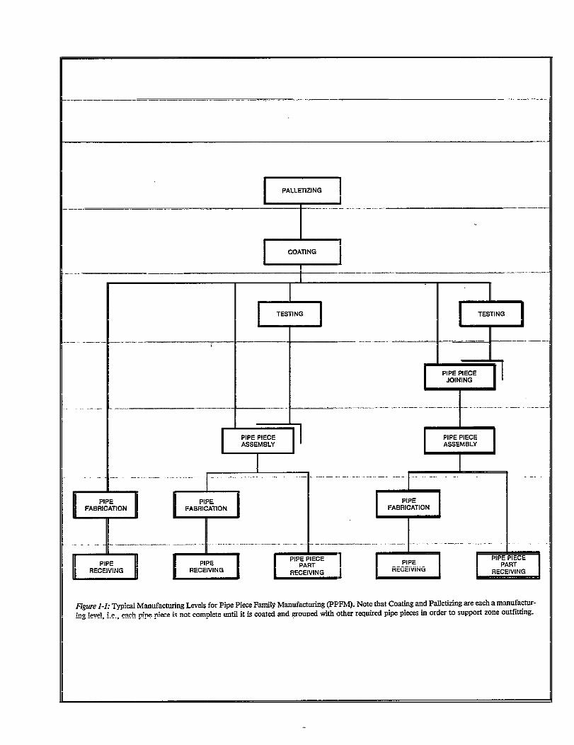
figure 1-2: Typical Classifications of Product Aspects for Pipe piece Family Manufacturing (PPFM). System is absent and zone has virtually nosignificance until palletizing. Pipe shop organization is based only on problem area and stage except for palletizing. Typical problem area subdivi-sions are presented in Appendix A.
p
The goal for selecting families and planning their routes isto utilize production-line principles. A production line freesworkers from having to plan a work sequence for each pipepiece. Instead, they concentrate on executing normal workprocesses. Because of this expertise, workers are better able toparticipate in constant evaluation and improvement of workmethods. However, a production line cannot free workersfrom unnecessary, repetitive planning chores unless:
Ž fabrication problems are anticipated by people who per-form design and material definition, and
Ž shop planning and scheduling is consistent withproduction-line principles.
The production-line principles are:● standardization of processes,Ž simplifiction and specialization of operations,Ž establishment of fixed work stations,Ž moving work pieces along a fixed route, andŽ designating positions for workers or teams of workers.
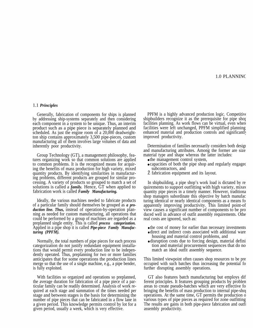
Figure 1-1 illustrates typical manufacturing levels and basiclogic used by a competitive shipbuilder to organize produc-tion lines and work flows for both manual and automatedoperations. Coating and palleting are each included as adistinct manufacturing level necessary for supporting zoneoutfitting.
Figure 1-2 shows associated classifications consistent with aproduct-oriented work breakdown.1 The product aspectsdescribed are noteworthy. System is absent and zone has vir-tually no significance until palletizing. As long as each pipe
iece is produced by its scheduled pallet date, the organiza-tion of production lines and work flows are based only onproblem area and stage. In other words, pipe-shop operationsare idealized without being encumbered by having to separatepipe pieces per ship or per system.
Figures 1-1 and 1-2 are examples of the logic necessary forany mix of pipe-piece requirements to establish
● pipe-piece families,● production lines, andŽ work flows which optimize use of facilities.
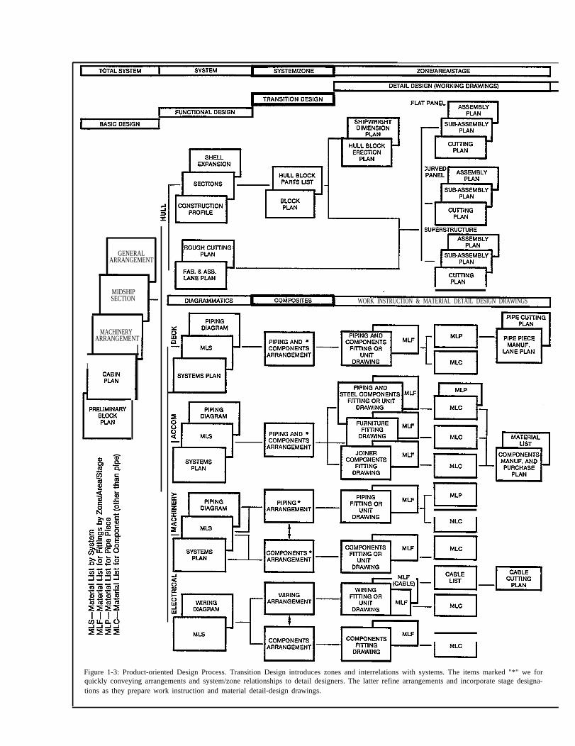
1.2 Design
As shown in Figure 1-3, modem shipbuilding technologyrequires that de-sign be truly an aspect of planning. As adesign effort progresses, planning requirements change for-mats in order to:
“Product Work Breakdown Structure - November 1980” by Y. Okayama
●
●
●
●
●
describe a ship as a system, address individual systems,provide an interrelationship between systems and zones,produce design details organized by relatively small in-crements for assembly work classified by zone, problemarea and stage, and finally,subdivide the latter into work instructions for prere-quisite fabrication work.
1.2.1 Functional design is the first stage for planning fabri-cation activities. For pipe-piece fabrication several keyelements are determined:
● diameter,● material,● service pressure,Ž testing requirements by system, and● surface treatment.
Using standards as much as possible, functional designersdefine all material requirements for each system diagram-matic. The material so identified is also organized by rela-tively large zones sequenced in the order that a ship will beerected. The format for such integrated information is calledMLS - Material List by (ship’s functional) System (by pur-chasing zone).
MLS indicate what materials are required and approxi-mately where and when they are required. Although portionsare necessarily estimates, MLS are practical enough for faststart-up of material ordering before detail design commences.Early resolution of difficult material procurements is essentialfor productive PPFM.
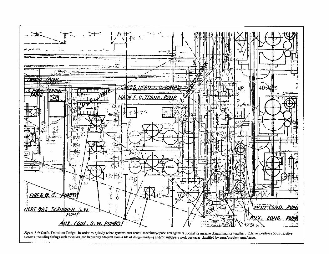
1.2.2 Transition design addresses the shift from system tozone orientation. As shown in Figure 1-4, system diagram-matic are quickly routed, often freehand, on machineryarrangement drawings. These serve as analytical tools for ex-amination of such aspects as:
Ž access for safe and efficient equipment operation,Ž relative positions of piping and hull structure,● maximum utilization of straight pipe,Ž pipes grouped in parallel to facilitate assembly,Ž access for outfitting on-unit, on-block and on-board,
and● inclusion of all systems.
and L.D. Chirillo for the National Shipbuilding Research Program.
GENERALARRANGEMENT
MIDSHIPSECTION
MACHINERYARRANGEMENT
I
WORK INSTRUCTION & MATERIAL DETAIL DESIGN DRAWINGS
Figure 1-3: Product-oriented Design Process. Transition Design introduces zones and interrelations with systems. The items marked "*" we forquickly conveying arrangements and system/zone relationships to detail designers. The latter refine arrangements and incorporate stage designa-tions as they prepare work instruction and material detail-design drawings.
51 55 56 57
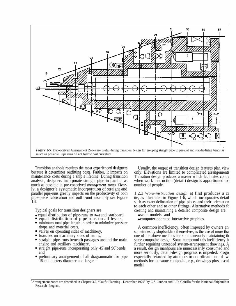
Figure 1-5: Preconceived Arrangement Zones are useful during transition design for grouping straight pipe in parallel and standardizing bends asmuch as possible. Pipe runs do not follow boil curvature.
Transition analysis requires the most experienced designersbecause it determines outfitting costs. Further, it impacts onmaintenance costs during a ship’s lifetime. During transitionanalysis, designers incorporate straight pipe in parallel asmuch as possible in pre-conceived arrangement zones.2 Clear-ly, a designer’s systematic incorporation of straight andparallel pipe-runs greatly impacts on the productivity of bothpipe-piece fabrication and outfit-unit assembly see Figure1-5.
Typical goals for transition designers are● equal distribution of pipe-runs to Port and starboard.●
●
●
●
●
●
●
equal distribution of pipe-runs on-all levels, minimum total pipe length in order to minimize pressuredrops and material costs,valves on operating sides of machinery,branches on machinery sides of mains,straight pipe-runs beneath passages around the mainengine and auxiliary machinery,straight pipe-runs incorporating only 450 and 900 bends,andpreliminary arrangement of all diagrammatic for pipe15 millimeters diameter and larger.
Z Arrangement zones are described in Chapter 3.0, “Outfit Planning - DecemResearch Program.
Usually, the output of transition design features plan viewonly. Elevations are limited to complicated arrangementsTransition design produces a master which facilitates controwhen work-instruction (detail) design is apportioned to anumber of people.
1.2.3 Work-instruction design at first produces a coite, as illustrated in Figure 1-6, which incorporates detailsuch as exact delineation of pipe pieces and their orientationto each other and to other fittings. Alternative methods focreating and maintaining a detailed composite design are:
● scale models. and● computer-operated interactive graphics.
A common inefficiency, often imposed by owners andsometimes by shipbuilders themselves, is the use of more thanone of the above methods for simultaneously maintaining thesame composite design. Some compound this inefficiency byfurther requiring unneeded system-arrangement drawings. Asa result, design manhours are unnecessarily consumed andmore seriously, detaill-design progress is impeded. Progreespecially retarded by attempts to coordinate use of twomethods for the same composite, e.g., drawings plus a scalemodel.
ber 1979” by C.S. JonSon and L.D. Chirillo for the National Shipbuilding
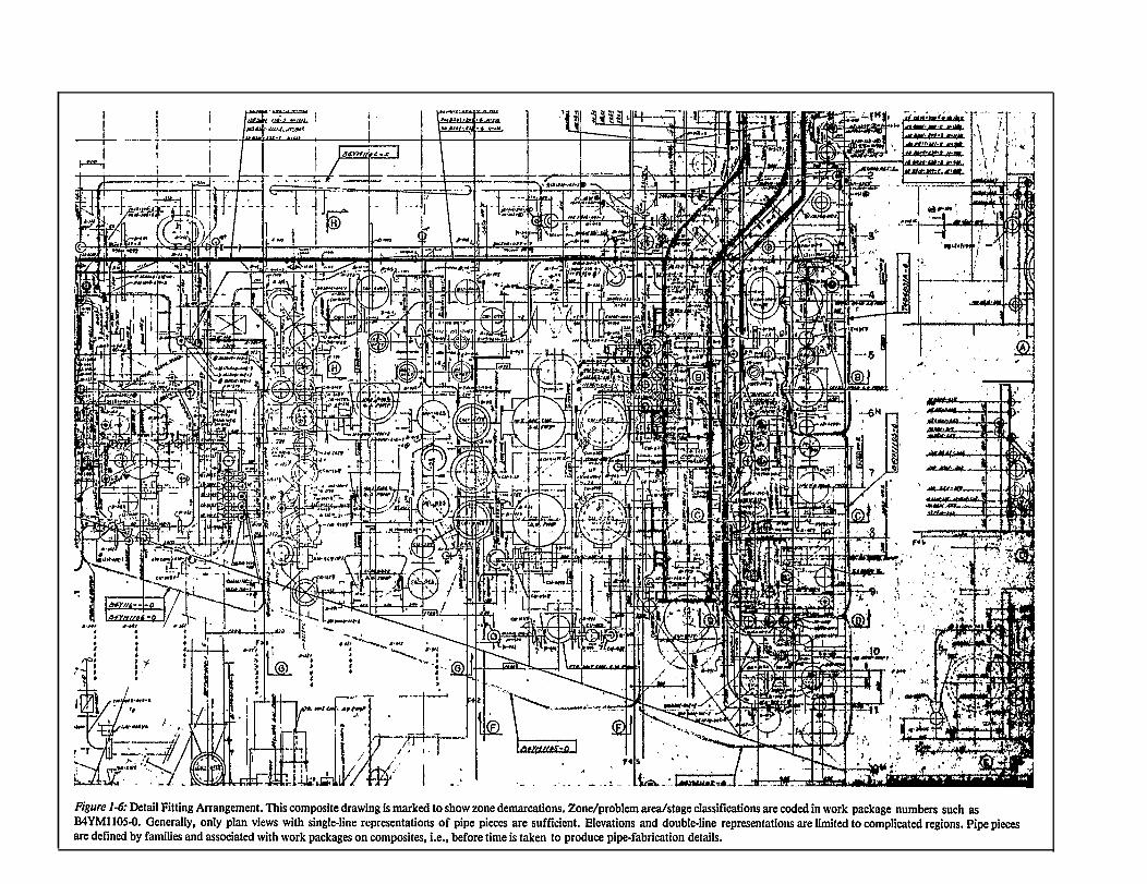
Figure 1-7: Orthographic pipe-piece fabrication-work instruction.
Detailed composites of any kind are required by shipbuild-ers only for:
● material definition,● orientation of fittings relative to each other for assembly
work instructions, and● details sufficient for fabrication work instructions.
As practical methods exist for readily digitizing from bothcomposite drawings and scale models, computers can supple-ment any technique used for creating a composite design.3
Computers are already used to produce pipe-piece fabricationinstructions, including their material lists, in various formats,e.g.:
● orthographic (Figure 1-7),● isometric, andŽ symbolic (Figure 1-8).
Symbolic pipe-piece details, now widely accepted, are pre-ferred because they are digitized. They are readily combinedand computer processed together with pentinent productioncontrol data, e.g., pipe-piece family identifiers, assembly-work package numbers and material lists. Start fabricationand palletizing dates are incorporated so that a single portionof a printout contains all needed planning and schedulingdata for each pipe piece. Obviously, necessary revisions areeasier to control when all required information appears onone document.
When work instructions are less geometric and morenumeric, the necessity for accuracy is reduced to essentials.Even when computers are used, more wherewithal is neededto produce geometrically accurate sketches. On geometricalsketches everything must be accurate, whereas on numericalpresentations only major points must be accurate.4
Although digital notations are more effective and morenaturally processed by computers, some shipbuilders contin-ue to apply computer-aided design tools to produce conven-tional pipe-piece sketches and their material lists. Some arecomputer-producing sketches and employing independentmaterial control programs. There is inherent duplication ofeffort and significantly increased opportunity for human er-ror. Producing pipe-piece sketches by computer can bejustified if it is an interim measure pending
● training workers to interpret digitized notations, orŽ adoption of numerically-controlled fabrication methods.
3 “Photogrammetric Dimensioning of Ships’ Engine-room Models-March 198Research Program.
4 Attributed to K. Ogawa, IHI International Division by C.J. Starkenburg, Technology at Avortdale” to the REAPS Technical- Symposiun 14-16 Oct
Otherwise, the computer is being used to produce moreaccurately and more quickly, archaic notions. This is aparadox.
Regardless of the degree of automation, designers mustprovide the following data as appropriate for each pipe-piecework instruction:
● required length of raw pipe,Ž required other materials, e.g., flange, elbow, tee, etc.,● angle and dimensions for bends,● margins required for bender grip and flange fitting,● angle between main and branch,
1” by J.F. Kenefick and L.D. Chirillo for the National Shipbuilding
Avondale Shipyards, Inc., in the presentation “Implementing IHIober 1980, Philadelphia, Pennsylvania.
Figure 1-8: Symbolic pipe-piece fabrication-work instructions aRe natural for cost-effective computer processing.
● flange orientation,● branch shape,● branch position,● material quantities for a complete MLP,Ž finishing requirements,Ž family identifier,● end preparation for welding,● welding specification,● pallet identification,● pipe-piece identification,● special work instructions (e.g., loose fitting a flange),● flange thickness, and● distance from flange face to branch centerline, etc.
Figure 1-9 illustrates how such data can be coded and appliedto a specific pipe piece.
10
Many pipe-piece drawings must be developed for each newship design. The design process follows clearly defined stepssome of which require much computation. Others requirerepetitive reference to basic design data. Thus, computer-aided design tools improve timeliness, accuracy and produc-tivity. Such programs typically provide:
●
●
●
●
●
input-data error checking,modification of input data via staudards,exact material quantities,fabrication information, anddata used for estimating, planning, scheduling, executingand evaluating, e.g., type and length of weld per pipepiece, painting area per pipe piece, man-hours per pipepiece, man-hours per unit weight, weight per pipe piece,etc.
11
How designers create and classify pipe-piece designs criti-cally influences both fabrication and assembly processes.When pipe pieces have to be bent, bends should be specifiedwhich can be formed after fabrication, e.g., bending afterflanges are attached. Such designs are beneficial because, asshown in Figure 1-10, they can be treated as straight pipepieces for most of their fabrication cycle. An appropriate tar-get for designers is to designate 40% of the total number ofpipe pieces as straight pipe or pipe that is to be bent afterfabrication.
Typical goals for people who perform work-instructiondesire are:
5.5 meter pipe-piece lengths for on-unit and on-blockoutfitting (access for cranes is always provided),not more than 3.0 meter pipe-piece lengths for on-boardoutfitting or otherwise limited by what an assemblyworker can safely handle,common supports for parallel pipe-runs and walkways,ganged bulkhead and deck penetrations, andstandard dimensions such as for bulkhead and deckpenetrations, branch positions and lengths, etc.
Figure l-IO: Regardless of whether manual or automated processes are used, tion work and are easily rolled from one work station to the next.
12
1.2.4 Material Definition During Work-inrtiuction Design
Planning functions performed by detail designers duringtheir preparation of work instructions are crucial for effectivePPFM. Such planning is the basis for all pipe-shop materialand production controls. The planning essentials which detaildesigners provide are:
Ž designation of pallets, i.e., work packages for outfitassembly work organized by zone/problem area/stage,and
Ž classification of pipe pieces within each pallet, i.e.,assigning each to a pipe-piece family, see Figure 1-11.
This matrix permits:detail design by zone,fabrication by pipe-piece family (problem area andstage), andgrouping of pipe pieces from various families by zonefor outfitting (palletizing), see Figure 1-12.
ASSEMBLING
pipe pieces which remain straight as long as possible, facilitate fabrica-
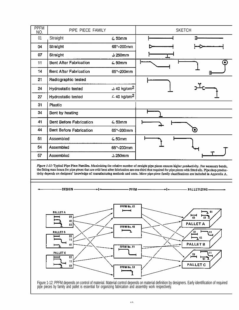
PPFMNO. PIPE PIECE FAMILY SKETCH
01 Straight
Figure 1-12: PPFM depends on control of material. Material control depends on material definition by designers. Early identification of requiredpipe pieces by family and pallet is essential for organizing fabrication and assembly work respectively.
13
C A D / C A M
MATERIALDEFINITION
DESIGN
. (CAM)2
MATERIALPROCUREMENT &MANUFACTURING
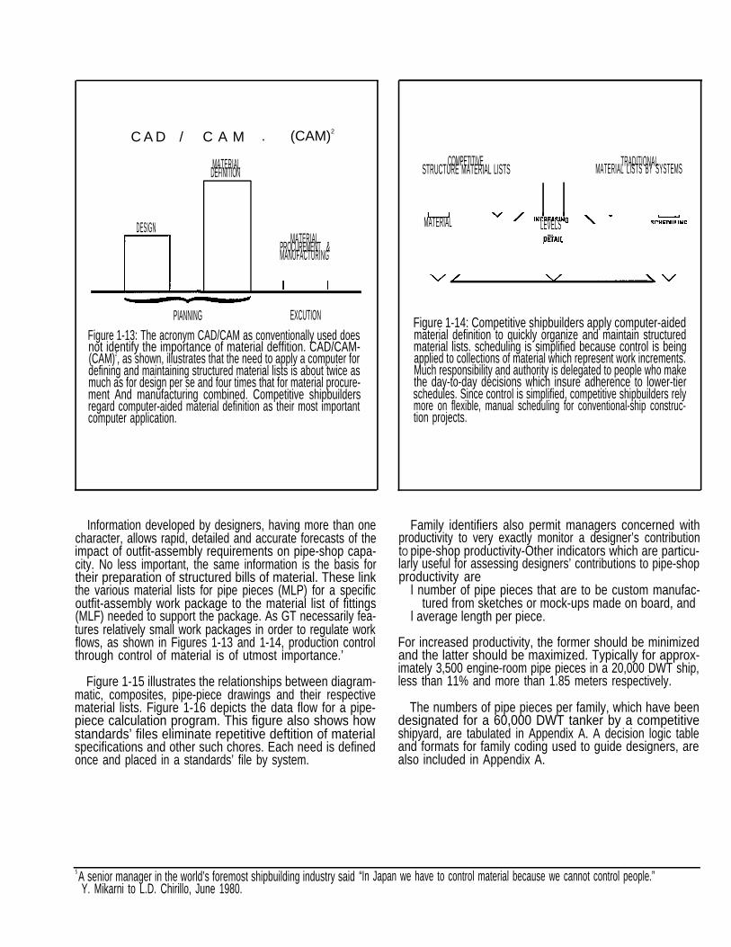
PIANNING EXCUTIONFigure 1-13: The acronym CAD/CAM as conventionally used doesnot identify the importance of material deffition. CAD/CAM-(CAM)2, as shown, illustrates that the need to apply a computer fordefining and maintaining structured material lists is about twice asmuch as for design per se and four times that for material procure-ment And manufacturing combined. Competitive shipbuildersregard computer-aided material definition as their most importantcomputer application.
COMPETITIVE TRADITIONALSTRUCTURE MATERIAL LISTS MATERIAL LISTS BY SYSTEMS
MATERIAL LEVELS
Figure 1-14: Competitive shipbuilders apply computer-aidedmaterial definition to quickly organize and maintain structuredmaterial lists. scheduling is simplified because control is beingapplied to collections of material which represent work increments.Much responsibility and authority is delegated to people who makethe day-to-day decisions which insure adherence to lower-tierschedules. Since control is simplified, competitive shipbuilders relymore on flexible, manual scheduling for conventional-ship construc-tion projects.
Information developed by designers, having more than onecharacter, allows rapid, detailed and accurate forecasts of theimpact of outfit-assembly requirements on pipe-shop capa-city. No less important, the same information is the basis fortheir preparation of structured bills of material. These linkthe various material lists for pipe pieces (MLP) for a specificoutfit-assembly work package to the material list of fittings(MLF) needed to support the package. As GT necessarily fea-tures relatively small work packages in order to regulate workflows, as shown in Figures 1-13 and 1-14, production controlthrough control of material is of utmost importance.’
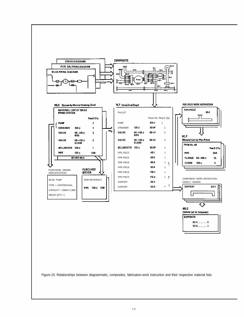
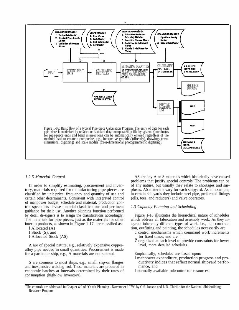
Figure 1-15 illustrates the relationships between diagram-matic, composites, pipe-piece drawings and their respectivematerial lists. Figure 1-16 depicts the data flow for a pipe-piece calculation program. This figure also shows howstandards’ files eliminate repetitive deftition of materialspecifications and other such chores. Each need is definedonce and placed in a standards’ file by system.
5 A senior manager in the world’s foremost shipbuilding industry said “In JapanY. Mikarni to L.D. Chirillo, June 1980.
Family identifiers also permit managers concerned withproductivity to very exactly monitor a designer’s contributiontO pipe-shop productivity-Other indicators which are particu-larly useful for assessing designers’ contributions to pipe-shopproductivity are
l number of pipe pieces that are to be custom manufac-tured from sketches or mock-ups made on board, and
l average length per piece.
For increased productivity, the former should be minimizedand the latter should be maximized. Typically for approx-imately 3,500 engine-room pipe pieces in a 20,000 DWT ship,less than 11% and more than 1.85 meters respectively.
The numbers of pipe pieces per family, which have beendesignated for a 60,000 DWT tanker by a competitiveshipyard, are tabulated in Appendix A. A decision logic tableand formats for family coding used to guide designers, arealso included in Appendix A.
we have to control material because we cannot control people.”
PURCHASE ORDERSPECIFICATION
BILGE PUMP
TYPE = CENTRIFUGAL
CAPACITY = 20M/H X 30M
REQ’D QTY= 1
RAW MATERIALS
PALLET
PUMP
STRAINER
PIPE PIECE
PIPE PIECE
PIPE PIECE
PIPE PIECE
PIPE PIECE
PIPE PIECE
SUPPORT
SUPPORT
Piece No. Req’d. Qty.
1
1
2
2
1
1
1
1
1
1
1COMPONENT WORK lNSTRUCTION(USUALLY standards)
Figure-15: Relationships between diagrammatic, composites, fabrication-work instruction and their respective material lists.
1 5
ESTIMATING QUANTITIES CALCULATINGEDITING INPUT CALCULATINGINPUT DATA PIPE PIECES ALS AND DETERMINING
PAINT AND MATERIAL
PIPE PIECEDRAWING
PRINTINGMATERIALLIST
Figure 1-16: Basic flow of a typical Pipe-piece Calculation Program. The entry of data for eachpipe piece is minimized by reliance on standard data incorporated in file by system. Coordinatesfor pipe-piece ends and bend intersections can be automatically entered regardless of themethod used to create a composite, e.g., interactive graphics (directly), drawings (two-dimensional digitizing) and scale models (three-dimensional photogrammetric digitizing).
1.2.5 Material Control
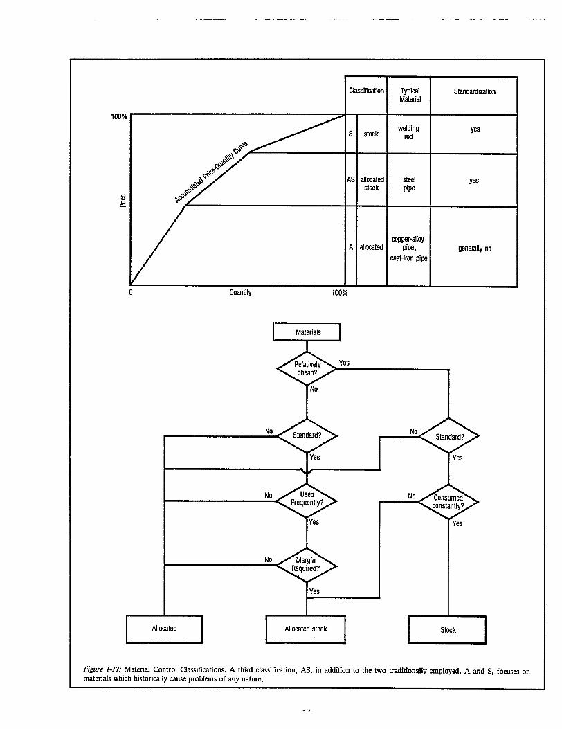
In order to simplify estimating, procurement and inven-tory, materials required for manufacturing pipe pieces areclassified by unit price, frequency and quantity of use and
s. Consistent with integrated controlcertain other determinantof manpower budget, schedule and material, production con-trol specialists devise material classifications and pertinentguidance for their use. Another planning function performedby detail de-signers is to assign the classifications accordingly.The materials for pipe pieces, just as the materials for otherinterim products, as shown in Figure 1-17, are classified as:
l Allocated (A)l Stock (S), andl Allocated Stock (AS).
A are of special nature, e.g., relatively expensive copper-alloy pipe needed in small quantities. Procurement is madefor a particular ship, e.g., A materials are not stocked.
S are common to most ships, e.g., small, slip-on flangesand inexpensive welding rod. These materials are procured ineconomic batches at intervals determined by their rates ofconsumption (high-low inventory).
c The controls are addressed in Chapter 4.0 of “Outfit Planning - November 19Research Program.
AS are any A or S materials which historically have causedproblems that justify special controls.6 The problems can beof any nature, but usually they relate to shortages and sur-pluses. AS materials vary for each shipyard. As an example,in certain shipyards they include steel pipe, preformed fittings(ells, tees, and reducers) and valve operators.
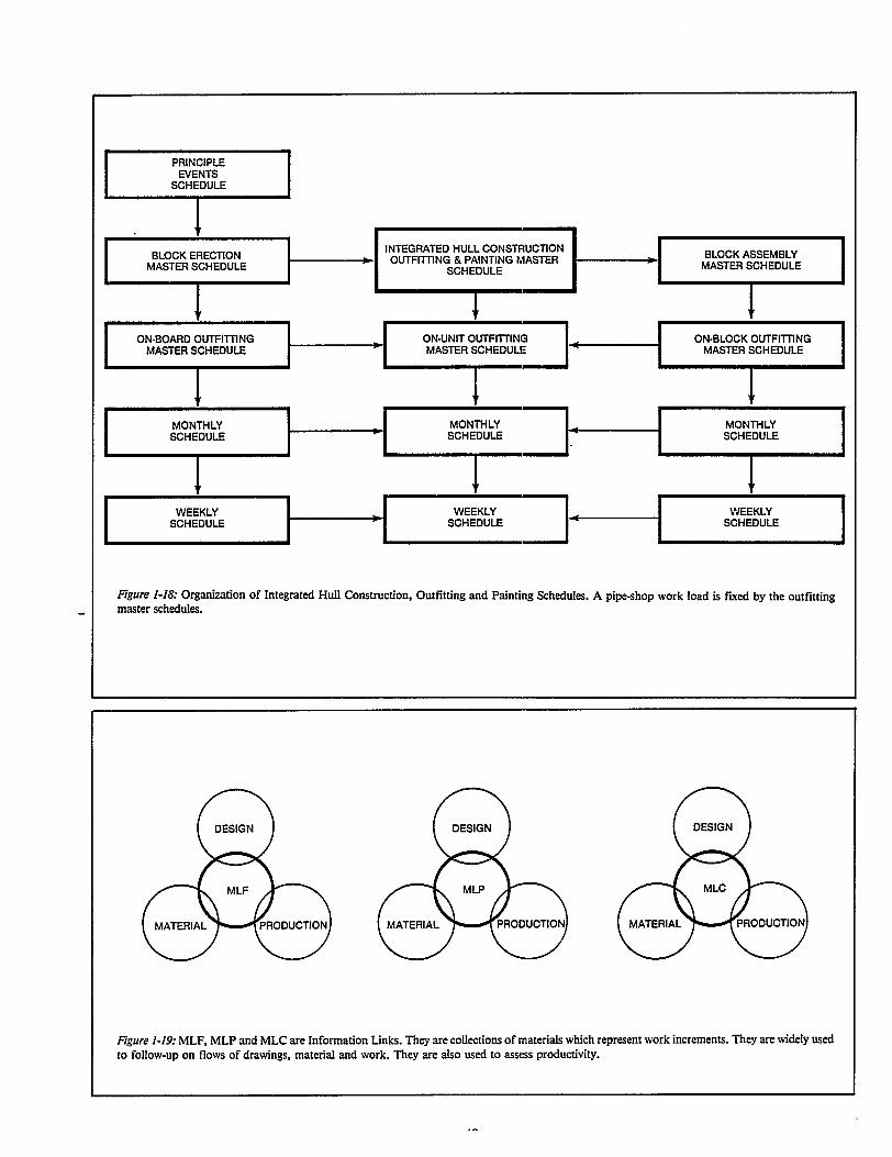
1.3 Capacity Planning and Scheduling
Figure 1-18 illustrates the hierarchical nature of scheduleswhich address all fabrication and assembly work. As they in-tegrate inherently different types of work, i.e., hull construc-tion, outfitting and painting, the schedules necessarily are:
c control mechanisms which command work incrementsfor fixed times, and are
Ž organized at each level to provide constraints for lower-level, more detailed schedules.
Emphatically, schedules are based upon:l manpower expenditure, production progress and pro-
ductivity indices that reflect normal shipyard perfor-mance, and
l normally available subcontractor resources.
79” by C.S. Jonson and L.D. Chirillo for the National Shipbuilding
ion
ces-
hop
ity
r
l
se
osuoo
bawfprfitf
1.3.1 In-house
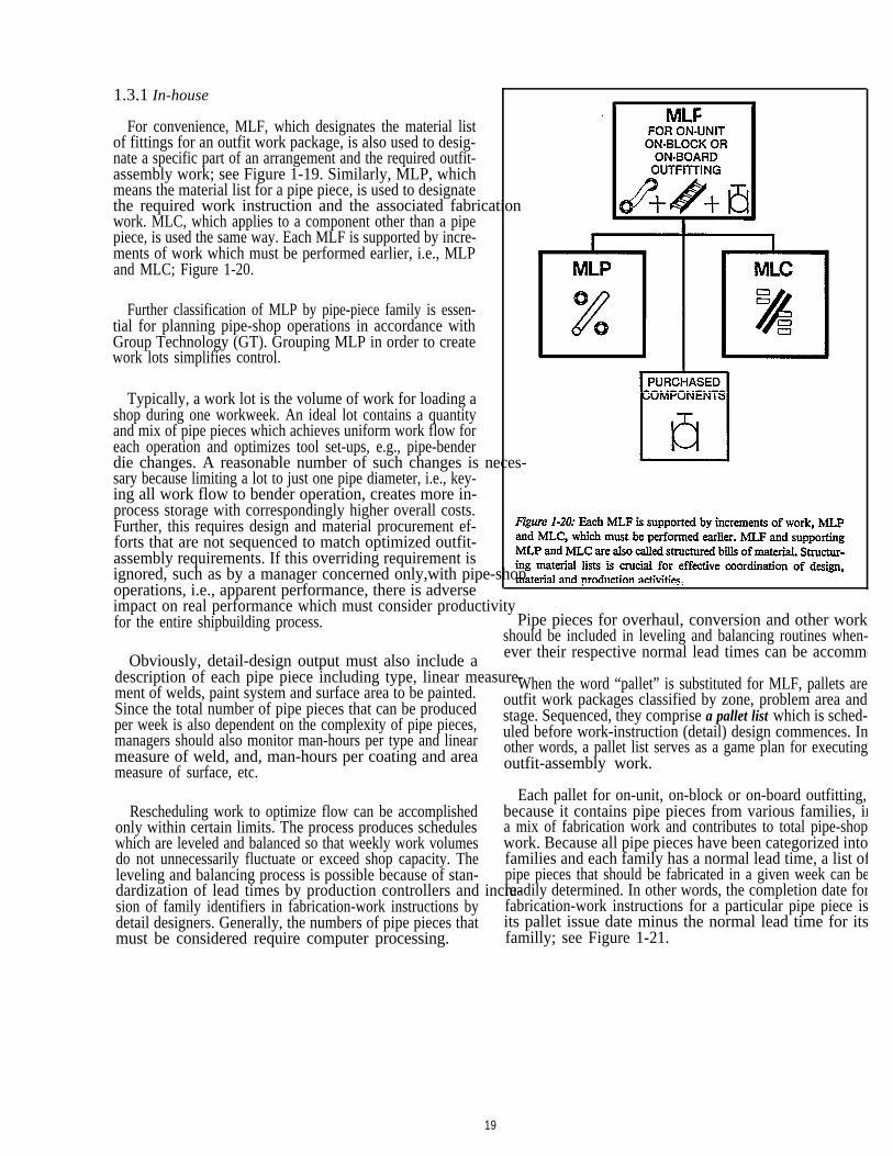
For convenience, MLF, which designates the material listof fittings for an outfit work package, is also used to desig-nate a specific part of an arrangement and the required outfit-assembly work; see Figure 1-19. Similarly, MLP, whichmeans the material list for a pipe piece, is used to designatethe required work instruction and the associated fabricatwork. MLC, which applies to a component other than a pipepiece, is used the same way. Each MLF is supported by incre-ments of work which must be performed earlier, i.e., MLPand MLC; Figure 1-20.
Further classification of MLP by pipe-piece family is essen-tial for planning pipe-shop operations in accordance withGroup Technology (GT). Grouping MLP in order to creatework lots simplifies control.
Typically, a work lot is the volume of work for loading ashop during one workweek. An ideal lot contains a quantityand mix of pipe pieces which achieves uniform work flow foreach operation and optimizes tool set-ups, e.g., pipe-benderdie changes. A reasonable number of such changes is nesary because limiting a lot to just one pipe diameter, i.e., key-ing all work flow to bender operation, creates more in-process storage with correspondingly higher overall costs.Further, this requires design and material procurement ef-forts that are not sequenced to match optimized outfit-assembly requirements. If this overriding requirement isignored, such as by a manager concerned only,with pipe-soperations, i.e., apparent performance, there is adverseimpact on real performance which must consider productivfor the entire shipbuilding process.
Obviously, detail-design output must also include adescription of each pipe piece including type, linear measument of welds, paint system and surface area to be painted.Since the total number of pipe pieces that can be producedper week is also dependent on the complexity of pipe pieces,managers should also monitor man-hours per type and linearmeasure of weld, and, man-hours per coating and areameasure of surface, etc.
Rescheduling work to optimize flow can be accomplishedonly within certain limits. The process produces scheduleswhich are leveled and balanced so that weekly work volumesdo not unnecessarily fluctuate or exceed shop capacity. Theleveling and balancing process is possible because of stan-dardization of lead times by production controllers and incsion of family identifiers in fabrication-work instructions bydetail designers. Generally, the numbers of pipe pieces thatmust be considered require computer processing.
19
e-
u-
Pipe pieces for overhaul, conversion and other workhould be included in leveling and balancing routines when-ver their respective normal lead times can be accommo
When the word “pallet” is substituted for MLF, pallets areutfit work packages classified by zone, problem area andtage. Sequenced, they comprise a pallet list which is sched-led before work-instruction (detail) design commences. Inther words, a pallet list serves as a game plan for executingutfit-assembly work.
Each pallet for on-unit, on-block or on-board outfitting,ecause it contains pipe pieces from various families, im mix of fabrication work and contributes to total pipe-shopork. Because all pipe pieces have been categorized into
amilies and each family has a normal lead time, a list ofipe pieces that should be fabricated in a given week can beeadily determined. In other words, the completion date forabrication-work instructions for a particular pipe piece iss pallet issue date minus the normal lead time for itsamilly; see Figure 1-21.
This methodology permits early capacity planning. First,man-hours required for each operation for each family iscomputed weekly. This results in a total man-hour require-ment by work station within each production line, e.g., cut-ting, bending, welding, assembling and coating. The workload is leveled and balanced for each line by examining theworkload on a particular work station and scheduling earlierany work exceeding normal capacity. For example, if thework load on a welding station presents a bottleneck, somepipe pieces which require welding are scheduled for the previ-ous week. The lead times shown in Figure 1-21 anticipate suchrescheduling based on a particular shipyard’s experience.
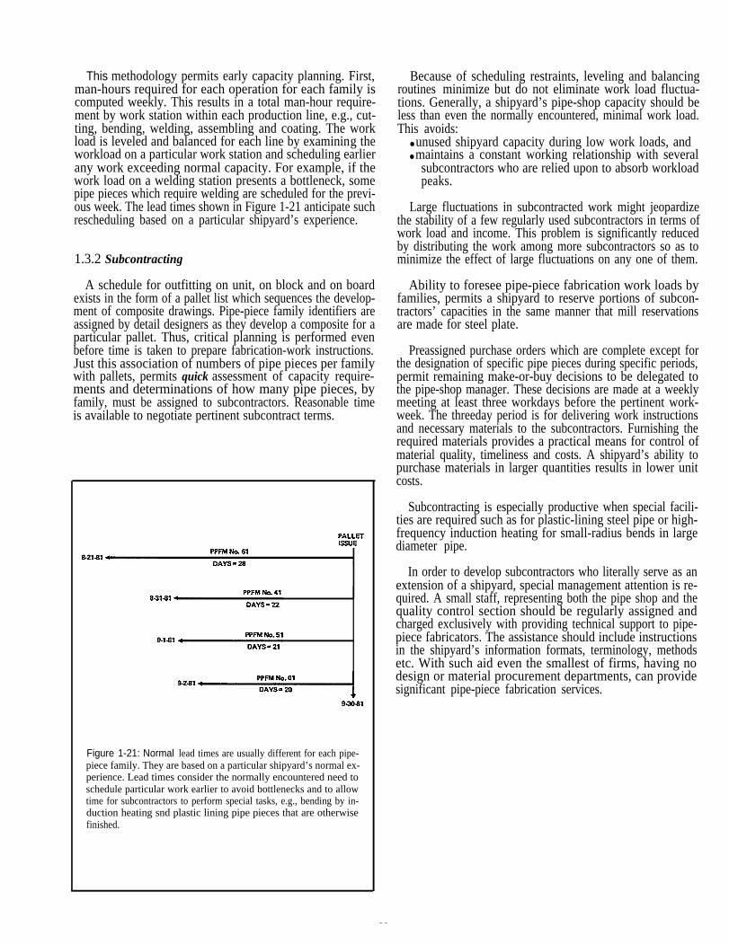
1.3.2 Subcontracting
A schedule for outfitting on unit, on block and on boardexists in the form of a pallet list which sequences the develop-ment of composite drawings. Pipe-piece family identifiers areassigned by detail designers as they develop a composite for aparticular pallet. Thus, critical planning is performed evenbefore time is taken to prepare fabrication-work instructions.Just this association of numbers of pipe pieces per familywith pallets, permits quick assessment of capacity require-ments and determinations of how many pipe pieces, byfamily, must be assigned to subcontractors. Reasonable timeis available to negotiate pertinent subcontract terms.
Figure 1-21: Normal lead times are usually different for each pipe-piece family. They are based on a particular shipyard’s normal ex-perience. Lead times consider the normally encountered need toschedule particular work earlier to avoid bottlenecks and to allowtime for subcontractors to perform special tasks, e.g., bending by in-duction heating snd plastic lining pipe pieces that are otherwisefinished.
20
Because of scheduling restraints, leveling and balancingroutines minimize but do not eliminate work load fluctua-tions. Generally, a shipyard’s pipe-shop capacity should beless than even the normally encountered, minimal work load.This avoids:
● unused shipyard capacity during low work loads, and● maintains a constant working relationship with several
subcontractors who are relied upon to absorb workloadpeaks.
Large fluctuations in subcontracted work might jeopardizethe stability of a few regularly used subcontractors in terms ofwork load and income. This problem is significantly reducedby distributing the work among more subcontractors so as tominimize the effect of large fluctuations on any one of them.
Ability to foresee pipe-piece fabrication work loads byfamilies, permits a shipyard to reserve portions of subcon-tractors’ capacities in the same manner that mill reservationsare made for steel plate.
Preassigned purchase orders which are complete except forthe designation of specific pipe pieces during specific periods,permit remaining make-or-buy decisions to be delegated tothe pipe-shop manager. These decisions are made at a weeklymeeting at least three workdays before the pertinent work-week. The threeday period is for delivering work instructionsand necessary materials to the subcontractors. Furnishing therequired materials provides a practical means for control ofmaterial quality, timeliness and costs. A shipyard’s ability topurchase materials in larger quantities results in lower unitcosts.
Subcontracting is especially productive when special facili-ties are required such as for plastic-lining steel pipe or high-frequency induction heating for small-radius bends in largediameter pipe.
In order to develop subcontractors who literally serve as anextension of a shipyard, special management attention is re-quired. A small staff, representing both the pipe shop and thequality control section should be regularly assigned andcharged exclusively with providing technical support to pipe-piece fabricators. The assistance should include instructionsin the shipyard’s information formats, terminology, methodsetc. With such aid even the smallest of firms, having nodesign or material procurement departments, can providesignificant pipe-piece fabrication services.
2.0 SHOP OPERATIONS
2.1 Work Flow
Increasing productivity through production-line principlesrequires standardized work processes, i.e., procedures, facili-ties, skills, man-hour requirements and durations. In theory,each production line consists of only sequenced activities,e.g., marking, cutting, assembling, etc., needed to fabricatepipe pieces for one family. As this would require needlessduplication of facilities, the pipe-piece flows for variousfamilies are selectively merged and coordinated. A singulargoal is to avoid, or at least minimize, reversals in the directionof basic work flow.
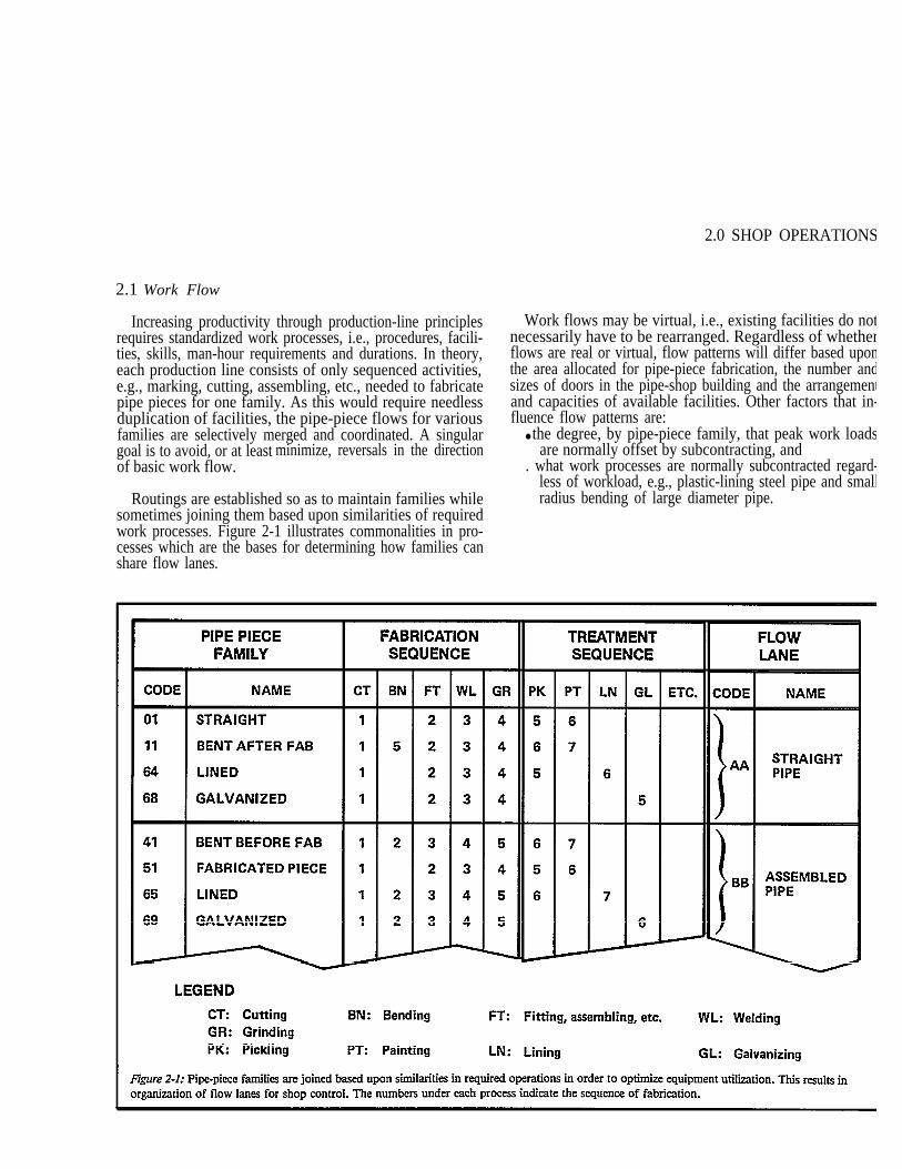
Routings are established so as to maintain families whilesometimes joining them based upon similarities of requiredwork processes. Figure 2-1 illustrates commonalities in pro-cesses which are the bases for determining how families canshare flow lanes.
Work flows may be virtual, i.e., existing facilities do notnecessarily have to be rearranged. Regardless of whetherflows are real or virtual, flow patterns will differ based uponthe area allocated for pipe-piece fabrication, the number andsizes of doors in the pipe-shop building and the arrangementand capacities of available facilities. Other factors that in-fluence flow patterns are:
● the degree, by pipe-piece family, that peak work loadsare normally offset by subcontracting, and
. what work processes are normally subcontracted regard-less of workload, e.g., plastic-lining steel pipe and smallradius bending of large diameter pipe.
1
BRANCH BRANCHONLY ONLY
7gure 2-2: Typical Work Flows resulting from joining pipe-piece families. A more detailed diagram is provided in Appendix B.
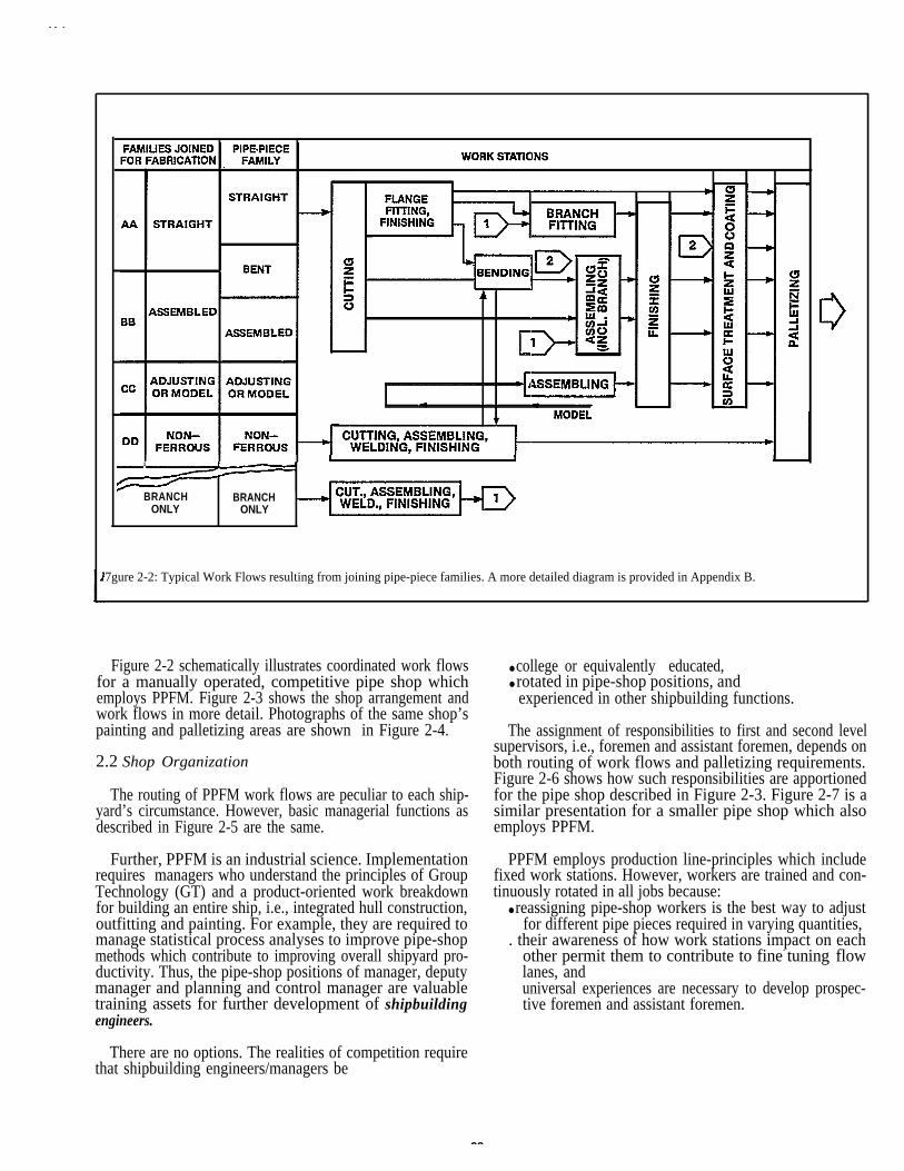
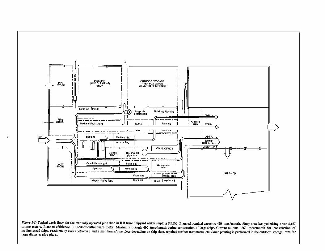
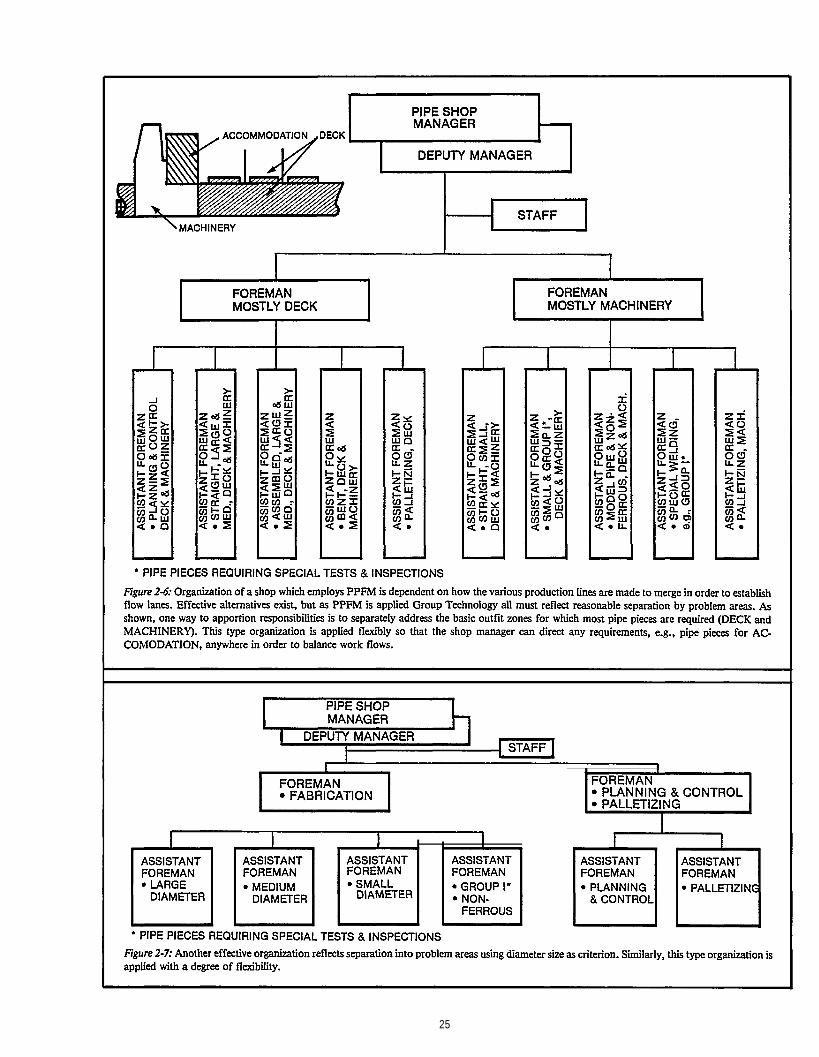
Figure 2-2 schematically illustrates coordinated work flows ● college or equivalently educated,for a manually operated, competitive pipe shop which ● rotated in pipe-shop positions, andemploys PPFM. Figure 2-3 shows the shop arrangement and experienced in other shipbuilding functions.work flows in more detail. Photographs of the same shop’spainting and palletizing areas are shown in Figure 2-4. The assignment of responsibilities to first and second level
supervisors, i.e., foremen and assistant foremen, depends on2.2 Shop Organization both routing of work flows and palletizing requirements.
Figure 2-6 shows how such responsibilities are apportionedThe routing of PPFM work flows are peculiar to each ship- for the pipe shop described in Figure 2-3. Figure 2-7 is a
yard’s circumstance. However, basic managerial functions as similar presentation for a smaller pipe shop which alsodescribed in Figure 2-5 are the same. employs PPFM.
Further, PPFM is an industrial science. Implementation PPFM employs production line-principles which includerequires managers who understand the principles of Group fixed work stations. However, workers are trained and con-Technology (GT) and a product-oriented work breakdown tinuously rotated in all jobs because:for building an entire ship, i.e., integrated hull construction, ● reassigning pipe-shop workers is the best way to adjustoutfitting and painting. For example, they are required to for different pipe pieces required in varying quantities,manage statistical process analyses to improve pipe-shop . their awareness of how work stations impact on eachmethods which contribute to improving overall shipyard pro-ductivity. Thus, the pipe-shop positions of manager, deputymanager and planning and control manager are valuabletraining assets for further development of shipbuildingengineers.
other permit them to contribute to fine- tuning flowlanes, anduniversal experiences are necessary to develop prospec-tive foremen and assistant foremen.
There are no options. The realities of competition requirethat shipbuilding engineers/managers be
22
23
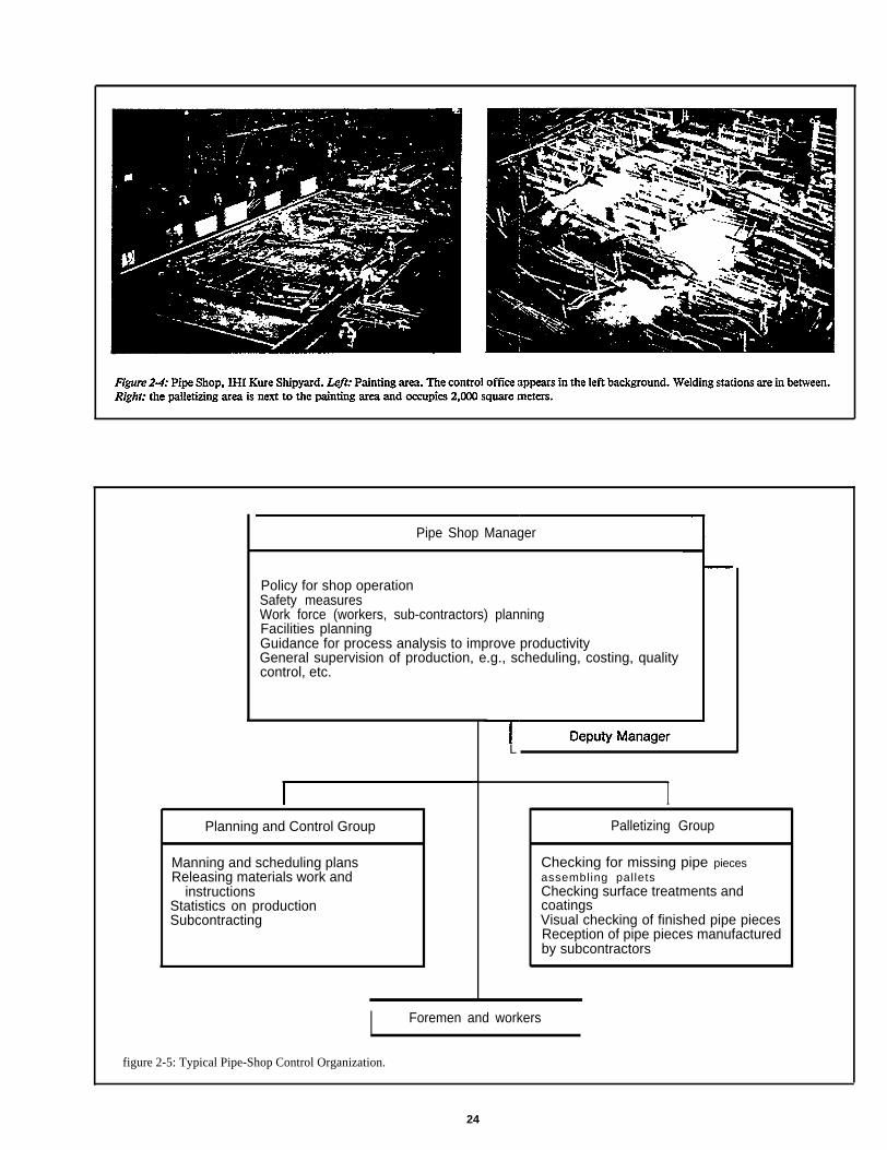
Pipe Shop Manager
Policy for shop operationSafety measuresWork force (workers, sub-contractors) planningFacilities planningGuidance for process analysis to improve productivityGeneral supervision of production, e.g., scheduling, costing, qualitycontrol, etc.
Planning and Control Group
Manning and scheduling plansReleasing materials work and
instructionsStatistics on productionSubcontracting
L
IPalletizing Group
Checking for missing pipe piecesassembling palletsChecking surface treatments andcoatingsVisual checking of finished pipe piecesReception of pipe pieces manufacturedby subcontractors
I Foremen and workers
figure 2-5: Typical Pipe-Shop Control Organization.
24
25
2.3 Work Load Forecasting
Workload is governed by requirements imposed by outfitassembly schedules which virtually disregard pipe-shopcapacity and backlog. The work thus imposed must bematched to available shop and subcontractor capacities inorder to schedule efficient PPFM. Necessarily, there must beconsideration of:
. long-term measures, and
. urgent problems which demand immediate solutions.
Changes in manpower and facilities which result from suchconsiderations, should be consistent with the economic necess-ity to maintain in-house capacity at a relatively modest leveland to regularly rely on subcontractors.
2.3.1 Long Term
Plans to adjust facilities, manning and subcontracting poli-cies should be based on the total number of required pipepieces or man-hours estimated for about the next six months.Circumstances sometimes require that the capacities of sub-contractors be immediately reserved dependent upon theircapacities relative to expected other demands.
26
2.3.2 Intermediate
Intermediate plans are based upon computer-aided analysisof pipe-piece requirements for the next two months. Theseare prepared separately for each pipe-piece family and workprocess as shown in Appendix C. Preparations are made forscheduling accordingly. If the workload greatly exceeds shopcapacity, intermediate plans are revised in order to subcon-tract more work. Printouts are then obtained separately forin-house and subcontract work.
2.3.3 Weekly
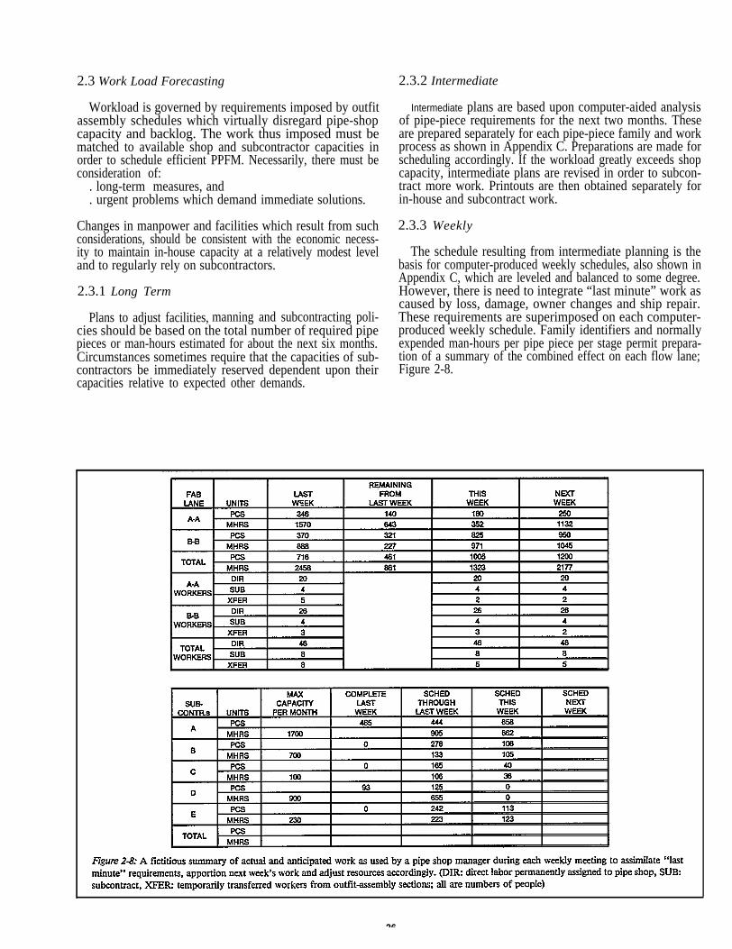
The schedule resulting from intermediate planning is thebasis for computer-produced weekly schedules, also shown inAppendix C, which are leveled and balanced to some degree.However, there is need to integrate “last minute” work ascaused by loss, damage, owner changes and ship repair.These requirements are superimposed on each computer-produced weekly schedule. Family identifiers and normallyexpended man-hours per pipe piece per stage permit prepara-tion of a summary of the combined effect on each flow lane;Figure 2-8.
A summary and a proposed plan for a following week’soperations are prepared by the shop’s planning and produc-tion control manager and are the principal topics at eachweekly meeting convened by the shop manager. Foremen andassistant foremen comment about the status of their respec-tive areas of cognizance. Adjustments are made and a plan isfinalized. Having commensurate authority, the shop managercan direct:
. transfer of workers between flow lanes,
. overtime, and● assignment of more work to pre-approved subcon-
tractors.
As another option, outfit progress permitting, temporarytransfer of assembly workers to the pipe shop could be re-quested. Obviously, the flexibility with which a manager canrespond is dependent upon how well workers are trained toperform at various work stations.
After the week’s work is determined, further leveling andbalancing is performed and reflected in detail schedules foreach work station within a flow lane. Operators further refinesuch schedules within limits of their portions of a lot and byhalf day periods in order to optimize sequences at each workstation.
Thus, planning and scheduling for PPFM proceeds inlevels of increasing detail. At first, planners are concernedwith identifying all required resources. Next, capacity plan-ning is accomplished to minimize work fluctuations. A weekbefore start of fabrication, plans for the next lot are com-pleted and specific work is ordered. Finally, day-todayoperational adjustments are made.
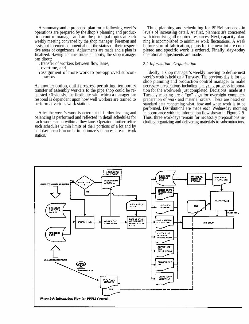
2.4 Information Organization
IdealIy, a shop manager’s weekly meeting to define nextweek’s work is held on a Tuesday. The previous day is for theshop planning and production control manager to makenecessary preparations including analyzing progress informa-tion for the workweek just completed. Decisions made at aTuesday meeting are a “go” sign for overnight computer-preparation of work and material orders. These are based onstandard data concerning what, how and when work is to beperformed. Distributions are made each Wednesday morningin accordance with the information flow shown in Figure 2-9Thus, three workdays remain for necessary preparations in-cluding organizing and delivering materials to subcontractors.
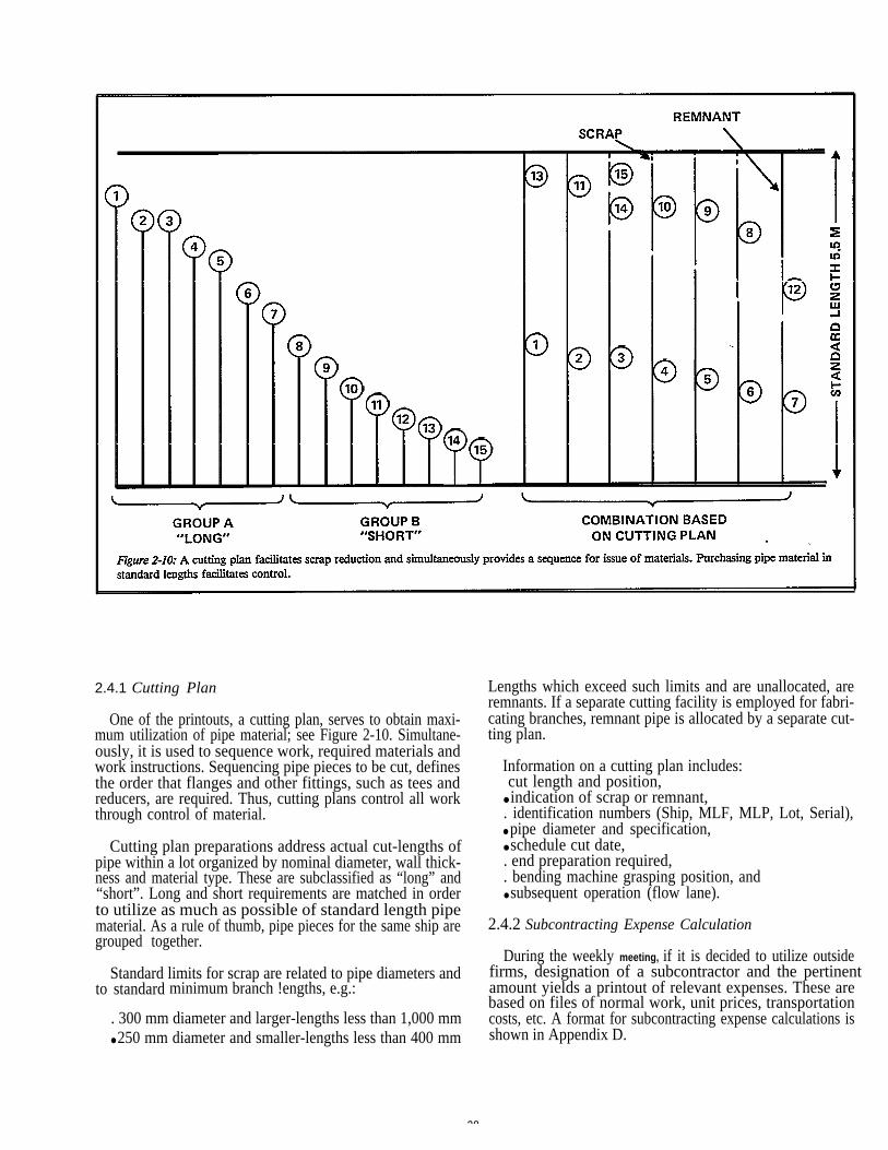
2.4.1 Cutting Plan
One of the printouts, a cutting plan, serves to obtain maxi-mum utilization of pipe material; see Figure 2-10. Simultane-ously, it is used to sequence work, required materials andwork instructions. Sequencing pipe pieces to be cut, definesthe order that flanges and other fittings, such as tees andreducers, are required. Thus, cutting plans control all workthrough control of material.
Cutting plan preparations address actual cut-lengths ofpipe within a lot organized by nominal diameter, wall thick-ness and material type. These are subclassified as “long” and“short”. Long and short requirements are matched in orderto utilize as much as possible of standard length pipematerial. As a rule of thumb, pipe pieces for the same ship aregrouped together.
Standard limits for scrap are related to pipe diameters andto standard minimum branch !engths, e.g.:
. 300 mm diameter and larger-lengths less than 1,000 mm● 250 mm diameter and smaller-lengths less than 400 mm
28
Lengths which exceed such limits and are unallocated, areremnants. If a separate cutting facility is employed for fabri-cating branches, remnant pipe is allocated by a separate cut-ting plan.
Information on a cutting plan includes: cut length and position,● indication of scrap or remnant,. identification numbers (Ship, MLF, MLP, Lot, Serial),● pipe diameter and specification,● schedule cut date,. end preparation required,. bending machine grasping position, and● subsequent operation (flow lane).
2.4.2 Subcontracting Expense Calculation
During the weekly meeting, if it is decided to utilize outsidefirms, designation of a subcontractor and the pertinent amount yields a printout of relevant expenses. These arebased on files of normal work, unit prices, transportationcosts, etc. A format for subcontracting expense calculations isshown in Appendix D.
2.4.3 Operations Control Lists
Additional printouts useful for operations control are● Branch-pipe List which groups branch-pipe pieces to be
fabricated in order to facilitate scheduling of pertinentwork stations.
● Pallet-comparition List which is MLF data arrangedmore conveniently for palletizing finished pipe pieces.Features are incorporated to facilitate checks of fabrica-tion-work progress.
. Group I Pipe-piece List which identifies pipe-pieces of aspecial nature which require tests that are to be witnessedby owner and/or classification society representatives.
Examples of operation control lists including those for sur-face treatment and coating schemes are in Appendix D.
2.4.4 Material-issue Confirmation
Typically, after operations control lists are prepared, perti-nent data is transferred to the material control system. Inresponse to a pipe-shop material-issue order, printouts listmaterial sorted by specified issue dates and destinations. Anexample is included in Appendix D. Materials which are notin-stock are identified on a separate “shortage list”.
2.4.5 In-process Identification
The numbers which appear on a cutting plan for each pipepiece to be fabricated identify ship, MLF, MLP, lot andserial. Once a lot is established for a particular week, bydefinition, all pipe pieces manufactured during that week willnot jeopardize their respective pallet issue dates.
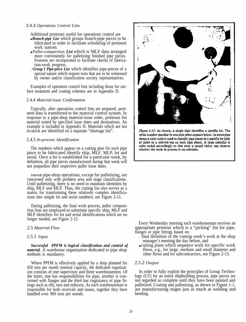
Internal pipe-shop operations, except for palletizing, areconcerned only with problem area and stage classifications.Until palletizing, there is no need to maintain identities byship, MLF and MLP. Thus, the cutting list also serves as amatrix for transforming these relatively complex identifica-tions into simple lot and serial numbers; see Figure 2-11.
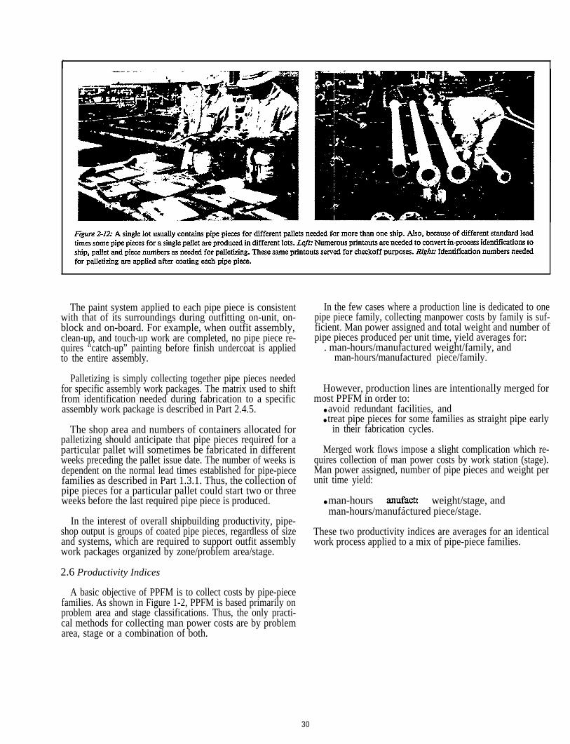
During palletizing, the final work process, pallet composi-tion lists are employed to substitute specific ship, MLF andMLP identifiers for lot and serial identifications which are nolonger needed, see Figure 2-12.
afl
2
lonpab
2.5 Material Flow
2.5.1 Input
Successful PPFM is logical classification and control ofmaterial. A warehouse organization dedicated to pipe shopmethods is mandatory.
Where PPFM is effectively applied by a shop planned for450 tons per month nominal capacity, the dedicated organizat-ion consists of one supervisor and three warehousemen. Ofthe latter, one has responsibilities for pipe, another is con-cerned with flanges and the third has cognizance of pipe fit-tings such as ells, tees and reducers. As each warehouseman isresponsible for both receivals and issues, together they havehandled over 900 tons per month.
29
Every Wednesday morning each warehouseman receives anppropriate printout which is a “picking” list for pipe,anges or pipe fittings based on:. final definition of the coming week’s work at the shop
manager’s meeting the day before, and● cutting plans which sequence work for specific work
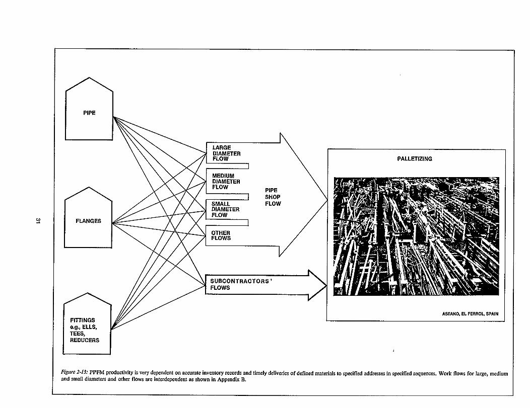
flows, e.g., for large, medium and small diameter andother flows and for subcontractors, see Figure 2-13.
.5.2 Output
In order to fully exploit the principles of Group Techno-gy (GT) for an entire shipbuilding process, pipe pieces areot regarded as complete until they have been painted andalletized. Coating and palletizing, as shown in Figure 1-1,re manufacturing stages just as much as welding andending.
I
In the few cases where a production line is dedicated to onepipe piece family, collecting manpower costs by family is suf-ficient. Man power assigned and total weight and number ofpipe pieces produced per unit time, yield averages for:
. man-hours/manufactured weight/family, and man-hours/manufactured piece/family.
However, production lines are intentionally merged formost PPFM in order to:
● avoid redundant facilities, and● treat pipe pieces for some families as straight pipe early
in their fabrication cycles.
Merged work flows impose a slight complication which re-quires collection of man power costs by work station (stage).Man power assigned, number of pipe pieces and weight perunit time yield:
● man-hours weight/stage, and man-hours/manufactured piece/stage.
These two productivity indices are averages for an identicalwork process applied to a mix of pipe-piece families.
The paint system applied to each pipe piece is consistentwith that of its surroundings during outfitting on-unit, on-block and on-board. For example, when outfit assembly,clean-up, and touch-up work are completed, no pipe piece re-quires “catch-up” painting before finish undercoat is appliedto the entire assembly.
Palletizing is simply collecting together pipe pieces neededfor specific assembly work packages. The matrix used to shiftfrom identification needed during fabrication to a specificassembly work package is described in Part 2.4.5.
The shop area and numbers of containers allocated forpalletizing should anticipate that pipe pieces required for aparticular pallet will sometimes be fabricated in differentweeks preceding the pallet issue date. The number of weeks isdependent on the normal lead times established for pipe-piecefamilies as described in Part 1.3.1. Thus, the collection ofpipe pieces for a particular pallet could start two or threeweeks before the last required pipe piece is produced.
In the interest of overall shipbuilding productivity, pipe-shop output is groups of coated pipe pieces, regardless of sizeand systems, which are required to support outfit assemblywork packages organized by zone/problem area/stage.
2.6 Productivity Indices
A basic objective of PPFM is to collect costs by pipe-piecefamilies. As shown in Figure 1-2, PPFM is based primarily onproblem area and stage classifications. Thus, the only practi-cal methods for collecting man power costs are by problemarea, stage or a combination of both.
30
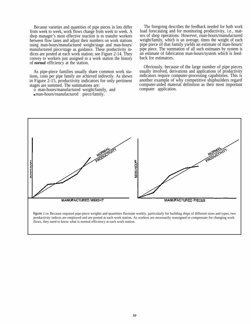
Because varieties and quantities of pipe pieces in lots differfrom week to week, work flows change from week to week. Ashop manager’s most effective reaction is to transfer workersbetween flow lanes and adjust their numbers on work stationsusing man-hours/manufactured weight/stage and man-hours/manufactured piece/stage as guidance. These productivity in-dices are posted at each work station; see Figure 2-14. Theyconvey to workers just assigned to a work station the historyof normal efficiency at the station.
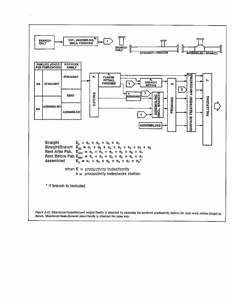
As pipe-piece families usually share common work sta-tions, costs per pipe family are achieved indirectly. As shownin Figure 2-15, productivity indicators for only pertinentstages are summed. The summations are:
o man-hours/manufactured weight/family, and● man-hours/rnanufactured piece/family.
The foregoing describes the feedback needed for both workload forecasting and for monitoring productivity, i.e., mat-ters of shop operations. However, rnan-hours/rnanufacturedweight/family, which is an average, times the weight of eachpipe piece of that family yields an estimate of man-hours/pipe piece. The summation of all such estimates by system isan estimate of fabrication man-hours/system which is feed-back for estimators.
Obviously, because of the large number of pipe piecesusually involved, derivations and applications of productivityindicators require computer-processing capabitities. This isanother example of why competitive shipbuilders regardcomputer-aided material definition as their most importantcomputer application.
figure 2-14: Because required pipe-piece weights and quantities fluctuate weekly, particularly for buiIding ships of different sizes and types, twoproductivity indices are employed and are posted at each work station. As workers are necessarily reassigned to compensate for changing workflows, they need to know what is normal efficiency at each work station.
32
3.0 SUGGESTIONS
3.1 Prerequisites
The key to improving pipe-shop productivity is to provideservices which allow workers to concentrate on their pre-scribed work, e.g., marking, cutting, welding, etc., withouttheir being disturbed by unforeseen events. This calls for ex-traordinary planning and scheduling by the pipe shop,manager particularly when determining a lot size per week.Further, PPFM is dependent upon extraordinary considera-tion of pipe-shop fabrication problems by people chargedwith design, material definition, and material control.
3.2 Statistical Control
Continuous improvements in pipe-shop work processesshould be derived from statistical analysis similar to thatpracticed by competitive shipbuilders.’ Standard ranges andtolerance limits based on normal performances are needed forsuch matters as straightness, overall length, alignment offlanges and orientation of flange bolt-holes Further, compe-titive shipbuilders establish standard ranges and tolerancelimits for pipe-pieces that are consistent with those for pipesupports and for flatness of decks. This permits them to landand weld even large outfit units without having to mark andcut supports to fit deck undulations.
3.3 Facilities
PPFM is a logic for organizing work regardless of whethera shop is manually or automatically operated. Group Tech-nology (GT) applied and fully exploited as PPFM is necessaryto determine if additional facilities are required. That is, it isimpossible to tell if new facilities are really needed withouthaving first achieved controlled work processes.
Just before the Arab “oil shock” of 1973 depressed theshipbuilding market, significant investments were made byshipbuilders abroad to completely automate functions such ascutting, flange mounting, welding and bending. Even auto-mated auxiliary equipment was instalIed for raw-pipe storageand issue, intermediate buffer storage and for machine-to-machine transfer. The work instructions used to control suchmachines are combined by computer with planning andscheduling data.
“Process Analysis via Accuracy Control - February 1982” by S. Nakan
In planning such installations it is normal to evaluateeconomical aspects only inconsideration of an expected pipe-shop fabrication work load. Equally important and oftenoverlooked, is the need to simultaneously address what is re-quired to design pipe pieces and define required materials inform and number suitable for computerization to supportzone outfitting. Equally important and often overlooked, iswhat is required to provide materials organized so as to bestobtain the benefits of automation. In other words, a pipe-piece fabrication system includes desigu, material definitionand material control through palletizing. No aspect of thesystem should be considered for improvement without evalu-ating its impact throughout the whoIe system.
3.4 Positioning Automated Devices
Special consideration is given the position of automateddevices. Positioning a device at the end of a flow line mayreduce work-in-process. Placing an automated device at thebeginning of a line might actually increase work-in-process,thereby increasing costs.
3.5 Straight Pipe
Straight pipe represents the largest of pipe piece familiesand requires the least fabrication time. It is naturally adapt-able to jigs and devices which can significantly improve pro-ductivity. Straight pipe is the easiest to transfer from stageto stage. The production line for straight pipe should be ar-ranged so as to provide minimum travel distance betweenmaterial entrance and product exit.
3.6 Branches
Branches belong either to the straight family or assembledfamily. As shown in Figure 2-15, a separate flow lane forbranch pieces feeds regular work flows at branch fitting andassembling stages. A branch-only flow lane is usually con-trolled by a cutting list which regulates the disposition ofremnants.
ishi and L.D. Chirillo for the National Shipbuilding Research Program.
3.7 Cold Bending
For other than straight pipe pieces, pipe-shop producti-vity is dependent on the design department adopting prin-ciples which allow cold bending to the maximum extent.Fitting work is usually tripled when assembled pipe is substi-tuted for pieces that could be cold bent.
When organizing cutting lists, pipe pieces within a lotshould be grouped together by size, wall thickness and bend-ing radius to minimize die changes.
3.8 Design
Composites, both in transition design and work instruc-tion (detail) design, are prepared in the context of a precon-ceived pallet list derived from a previous similar arrange-ment, i.e., a list of proposed work packages categorized byzone/problem area/stage. As the design develops, the palletlist is refined usually by making adjustments in zone boun-daries only. Sometimes, the developing design justifies split-ting a work package into two or combining two into one. Achange in stage is also possible.
Finalizing a pallet list as soon as possible is importantbecause it determines the sequence that MLP are prepared.That is, designers prepare pipe-piece details in a sequencedictated by pallet requirements. Thus, they continuouslyhave to shift from system to system and use the compositeprepared in transition design for check off purposes.
The composite prepared during work instruction design isused to prepare work instructions for individual pipe pieces,MLP. Once the coordinates for pipe-piece end points andbend intersection and other critical points are defined, all re-maining functions follow a pattern which requires muchcomputation. This non-creative phase is more quickly andmore accurately performed by computer. The computerproduces specific dimensions, exactly defined material,welding, coating and palletizing information as required forpipe-shop operation. The computer provides pipe-piecefamily classification, weight and data needed for planningand scheduling which is derived from normal rates for man-hours, progress and productivity per pipe-piece family.
Obviously, a computer can only fulfill a pipe-shopmanager’s complete needs when such feedback as fabrica-tion period, man-hours required and fabrication procedureper pipe-piece family are based on immediate past, normalpipe-shop performances.
3.9 Computer Scheduling and Leveling
Use of a computer is natural for calculating man-hoursrequired to produce each pipe piece based on master-filedata for controlled work processes. The computer derivesthe date on which fabrication must start for each pipe piece:start date equals pallet assembly date minus the normal leadtime for a specific pipe piece family. As shown in Figure 1-21,different pipe pieces can have different start-fabrication datesin order to meet a common pallet date.
35
The computer first calculates for each pipe-piece familyand for each flow lane, the man-hours required for cutting,bending, welding, assembling and finishing stages. Some-times work is heavily concentrated at one stage, e.g., a weld-ing station. Then, the computer schedules pipe pieces withlarge welding requirements, earlier but within the limits ofnormal lead times.
Such leveling by computer is not possible without feed-back which reflects a pipe shop’s latest normal perfor-mances. Moreover, large amounts of last minute require-ments such as for owner changes or repair work, requires-that peak leveling be performed manually.
3.10 Lot Size
In planning pipe-piece fabrication (work-load scheduling,material control scheme, etc.) a planning cycle of one weekis usually most practical. A rough lot size considered inoverall scheduling then corresponds to the work volume forone week’s production. As the total work volume that canbe handled in one week is constant, the amount of pipepieces than can be produced during one week depends onthe complexity of fabrication work required.
The distribution of work imposed by a lot does not nor-mally match the distribution of available shop capacity forbending, assembling, welding, etc. Apart from watching tosee that overall work volume does not greatly exceed totalshop capacity, more detailed work scheduling is required tolevel work-load peaks for certain work stages. For thisreason, detailed work schedules drawn up by individualoperators covering say half a day’s work at most, are usefulfor determining the actual work load for each workstation.
Leveling such peaks is conditioned on a certain amount offlexibility. Operators have to be capable of undertaking jobsin more than one work station.
3.11 Material Transfer and Storage
Pipe-shop work should flow in a single direction. That is,there should be no disruptive reverse flow. Since thetion at each work process is relatively short, a correspond-ingly high throughput of work pieces is necessary to fullyutilize available machinery. Therefore, sufficient means ofconveying and handling incoming material and outgoingproducts must be considered. The distance traveled by eachwork piece between stages should be minimized. Transferbetween stages could be accomplished by a number of alter-natives. The most productive approach is to have the workpiece delivered by the team completing the preceding stage.
Consideration of in-process storage for work piecesbetween stages is an important factor. While excessive floorspace should not be reserved for such storage, means shouldbe devised for this purpose. One such device is storage intiers to maximize floor space utilization. Whatever mediumis devised, intermediate storage should be capable of buffer-ing materials for one half to one work day.
Space and handling facilities for stock pipe should antici-pate one week’s operation. However, large diameter pipewhich requires excessive space should be limited to two tothree day’s stock depending on anticipated volume.
3.12 Special Work
Regardless of the effectiveness of PPFM, some separatefacility should exist for special work which would otherwisedisrupt regular work flows. Special work includes someowner changes at the last minute and ship repair work.
3.13 Progress Control
As shown in Figure 2-5, the main responsibility for work-progress control is assigned to a Planning and ControlGroup and to a Palletizing Group. However, foremen andworkers charged with shop operations are required to coop-erate by such means as pinpointing work behind scheduleand sorting pipe pieces emerging from the finishing stage ac-cording to surface treatment required at the next stage.
3.14 Control of Subsidiary Materials
Welding rods, adhesives and other such materials re-quired in a pipe shop are freely available to workers. Book-keeping to cover consumption is linked to associated itemssuch as flanges in order to assign costs to specific ship con-struction projects.
3.15 Pertinent Photographs
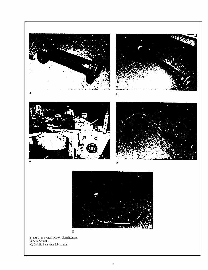
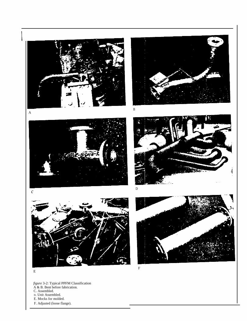
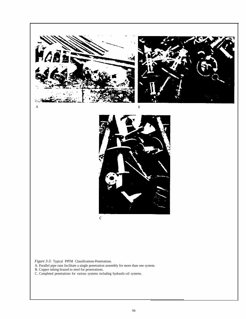
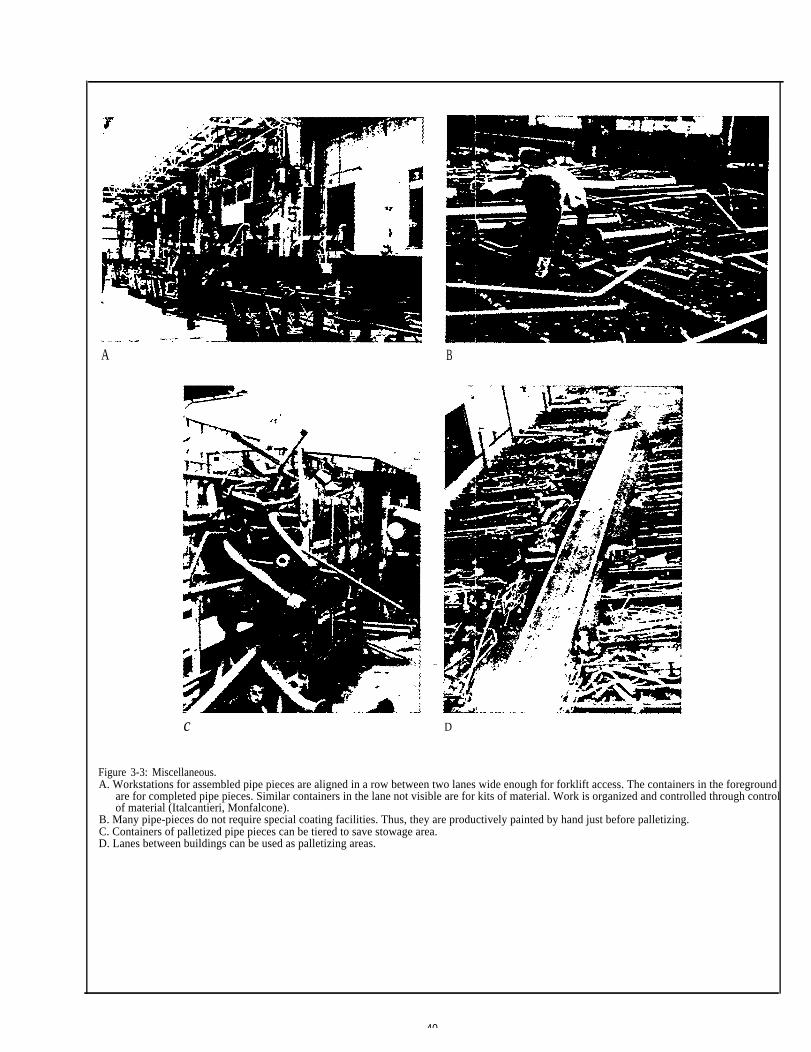
Figures 3-1 through 34 illustrate various aspects of PPFMin operation.
E
Figure 3-1: Typical PPFM Classifications.A & B. Straight.C, D & E. Bent after fabrication.
B
D
37
A
c
E
figure 3-2: Typical PPFM ClassificationA & B. Bent before fabrication.C. Assembled.D. Unit Assembled.E. Mocks for molded.F. Adjusted (loose flange).
B
D
F
A B
c
Figure 3-3: Typical PPFM Classifications-Penetrations.A. Parallel pipe runs facilitate a single penetration assembly for more than one system.B. Copper tubing brazed to steel for penetrations.C. Completed penetrations for various systems including hydraulic-oil systems.
39
A B
c D
Figure 3-3: Miscellaneous.A. Workstations for assembled pipe pieces are aligned in a row between two lanes wide enough for forklift access. The containers in the foreground
are for completed pipe pieces. Similar containers in the lane not visible are for kits of material. Work is organized and controlled through controlof material (Italcantieri, Monfalcone).
B. Many pipe-pieces do not require special coating facilities. Thus, they are productively painted by hand just before palletizing.C. Containers of palletized pipe pieces can be tiered to save stowage area.D. Lanes between buildings can be used as palletizing areas.
40

QUANTITIES OF PIPE PIECES BY FAMILIES FOR A 60,000 DWT TANKER
PPFM DIAMETERS IN MILLIMETERSSUB-
NO. 8 10 15 20 25 32 40 50 65 80 100 125 150 200 250 300 350 400 450 500 550 600 650 700 TOTALS
01 183 16 256 21 289 200 965
04 160 72 173 123 161 70 759
07 100 23 16 34 47 41 45 3 309
11 264 21 285 20 227 111 928
14 46 31 48 16 16 157
21 34 27 2 6 69
24 19 2 33 4 13 71
25 1 2 8 11
27 29 2 4 59 12 10 5 7 2 18 148
31 5 3 9 76 108 45 9 38 293
34 2 4 1 4 8 4 5 22 6 6 2 64
41 199 32 310 36 342 221 1,140
44 152 82 137 89 81 43 584
51 2 1 20 1 44 76 144
54 56 36 95 59 74 68 388
57 57 34 17 13 18 11 10 3 3 166
61 61 1 53 46 42 12 88 35 52 30 27 8 5 2 16 1 4 483
69 94 45 18 23 50 56 20 12 16 47 381
81 43 196 239
87 29 227 24 101 4 293 2 680
90 20 40 4 2 3 69
91 83 13 111 16 146 94 57 57 118 63 46 25 35 6 14 7 2 2 1 896
93 2 2
95 19 1 18 12 13 4 1 7 8 8 7 13 1 1 7 17 1 138
96 4 5 1 1 11
99 16 28 27 5 1 4 7 1 1 10 3 12 7 11 16 10 8 19 1 2 5 194I
TOTAL 9,289
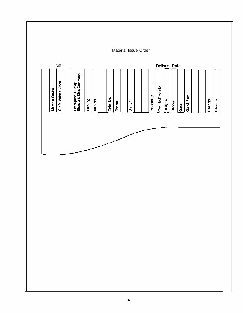
Material Issue Order
Store