Embed Size (px)
Citation preview
SERVICE MANUALPIONEER PUMP

3
PIONEER PUMP
TABLE OF CONTENTS
Introduction . . . . . . . . . . . . . . . . . . . . . . . . . . . . . . . . . . . . . . . . . . . . . . . . . . . . . . . . . . . . . . . . . . . . . . . . . . . . . . . . . . . . . . . . . . . . . . . . 4
Purpose and Scope of this Manual . . . . . . . . . . . . . . . . . . . . . . . . . . . . . . . . . . . . . . . . . . . . . . . . . . . . . . . . . . . . . . . . . . . . . . . . . . . . . . . . 4
Recording Model and Serial Numbers . . . . . . . . . . . . . . . . . . . . . . . . . . . . . . . . . . . . . . . . . . . . . . . . . . . . . . . . . . . . . . . . . . . . . . . . . . . . . 4
Safety Warnings and Notices . . . . . . . . . . . . . . . . . . . . . . . . . . . . . . . . . . . . . . . . . . . . . . . . . . . . . . . . . . . . . . . . . . . . . . . . . . . . . . . . . . . . 5
Vacuum Assist System . . . . . . . . . . . . . . . . . . . . . . . . . . . . . . . . . . . . . . . . . . . . . . . . . . . . . . . . . . . . . . . . . . . . . . . . . . . . . . . . . . . . . . 6
Main Components . . . . . . . . . . . . . . . . . . . . . . . . . . . . . . . . . . . . . . . . . . . . . . . . . . . . . . . . . . . . . . . . . . . . . . . . . . . . . . . . . . . . . . . . . . . . . 6
Theory of Operation . . . . . . . . . . . . . . . . . . . . . . . . . . . . . . . . . . . . . . . . . . . . . . . . . . . . . . . . . . . . . . . . . . . . . . . . . . . . . . . . . . . . . . . . . . . . 7
Disassembly and Assembly . . . . . . . . . . . . . . . . . . . . . . . . . . . . . . . . . . . . . . . . . . . . . . . . . . . . . . . . . . . . . . . . . . . . . . . . . . . . . . . . . . . . . 9
Priming Chamber and Posi-Valve® . . . . . . . . . . . . . . . . . . . . . . . . . . . . . . . . . . . . . . . . . . . . . . . . . . . . . . . . . . . . . . . . . . . . . . . . .18
Theory of Operation . . . . . . . . . . . . . . . . . . . . . . . . . . . . . . . . . . . . . . . . . . . . . . . . . . . . . . . . . . . . . . . . . . . . . . . . . . . . . . . . . . . . . . . . . . . .18
Disassembly and Assembly . . . . . . . . . . . . . . . . . . . . . . . . . . . . . . . . . . . . . . . . . . . . . . . . . . . . . . . . . . . . . . . . . . . . . . . . . . . . . . . . . . . . .21
Discharge Check Valve . . . . . . . . . . . . . . . . . . . . . . . . . . . . . . . . . . . . . . . . . . . . . . . . . . . . . . . . . . . . . . . . . . . . . . . . . . . . . . . . . . . . . 24
Theory of Operation . . . . . . . . . . . . . . . . . . . . . . . . . . . . . . . . . . . . . . . . . . . . . . . . . . . . . . . . . . . . . . . . . . . . . . . . . . . . . . . . . . . . . . . . . . . 24
Disassembly and Assembly . . . . . . . . . . . . . . . . . . . . . . . . . . . . . . . . . . . . . . . . . . . . . . . . . . . . . . . . . . . . . . . . . . . . . . . . . . . . . . . . . . . . 25
SAE Housing and Coupler . . . . . . . . . . . . . . . . . . . . . . . . . . . . . . . . . . . . . . . . . . . . . . . . . . . . . . . . . . . . . . . . . . . . . . . . . . . . . . . . . . 26
SAE Bracket (Engine Mount) Coupling . . . . . . . . . . . . . . . . . . . . . . . . . . . . . . . . . . . . . . . . . . . . . . . . . . . . . . . . . . . . . . . . . . . . . . . . . . . . 26
Disassembly and Assembly . . . . . . . . . . . . . . . . . . . . . . . . . . . . . . . . . . . . . . . . . . . . . . . . . . . . . . . . . . . . . . . . . . . . . . . . . . . . . . . . . . . . 26
Bearing Frame . . . . . . . . . . . . . . . . . . . . . . . . . . . . . . . . . . . . . . . . . . . . . . . . . . . . . . . . . . . . . . . . . . . . . . . . . . . . . . . . . . . . . . . . . . . . . 29
General Information . . . . . . . . . . . . . . . . . . . . . . . . . . . . . . . . . . . . . . . . . . . . . . . . . . . . . . . . . . . . . . . . . . . . . . . . . . . . . . . . . . . . . . . . . . . 29
Disassembly and Inspection . . . . . . . . . . . . . . . . . . . . . . . . . . . . . . . . . . . . . . . . . . . . . . . . . . . . . . . . . . . . . . . . . . . . . . . . . . . . . . . . . . . . 29
Reassembly . . . . . . . . . . . . . . . . . . . . . . . . . . . . . . . . . . . . . . . . . . . . . . . . . . . . . . . . . . . . . . . . . . . . . . . . . . . . . . . . . . . . . . . . . . . . . . . . . . 32
Pump End . . . . . . . . . . . . . . . . . . . . . . . . . . . . . . . . . . . . . . . . . . . . . . . . . . . . . . . . . . . . . . . . . . . . . . . . . . . . . . . . . . . . . . . . . . . . . . . . . 35
Theory of Operation . . . . . . . . . . . . . . . . . . . . . . . . . . . . . . . . . . . . . . . . . . . . . . . . . . . . . . . . . . . . . . . . . . . . . . . . . . . . . . . . . . . . . . . . . . . 35
Disassembly and Reassembly . . . . . . . . . . . . . . . . . . . . . . . . . . . . . . . . . . . . . . . . . . . . . . . . . . . . . . . . . . . . . . . . . . . . . . . . . . . . . . . . . . 36
Appendix . . . . . . . . . . . . . . . . . . . . . . . . . . . . . . . . . . . . . . . . . . . . . . . . . . . . . . . . . . . . . . . . . . . . . . . . . . . . . . . . . . . . . . . . . . . . . . . . . . 40
Troubleshooting Guide . . . . . . . . . . . . . . . . . . . . . . . . . . . . . . . . . . . . . . . . . . . . . . . . . . . . . . . . . . . . . . . . . . . . . . . . . . . . . . . . . . . . 47
4
PIONEER PUMP
INTRODUCTIONThank you for purchasing a Pioneer Centrifugal Pump . We are confident that you will enjoy long and satisfactory service from this product . This pump is designed for handling non-volatile, non-flammable, mild industrial corrosives, residues and slurries . We want you to be safe, so please operate the pump safely and in accordance with the guidelines, cautions and warnings written in this manual .
When your pump requires maintenance or repair, it is always a good idea to insist on only genuine Pioneer Pump repair parts . These parts are designed to give you the best life and performance with your pump . When we design the parts, we have your safety in mind . We wish you safe and productive pumping with your Pioneer Pump .
Purpose and Scope of this ManualThis manual provides information about the disassembly and repair of your Pioneer Pump . It is intended to be used by experienced technicians with the proper tools and workshop equipment, and by using the industry-accepted best practice for the safe and effective repair of your pump . Since one pump application is different from another, this manual cannot possibly cover each and every situation . If you have any questions about the procedures covered in this manual, please contact your Pioneer distributor or the nearest Pioneer company branch .
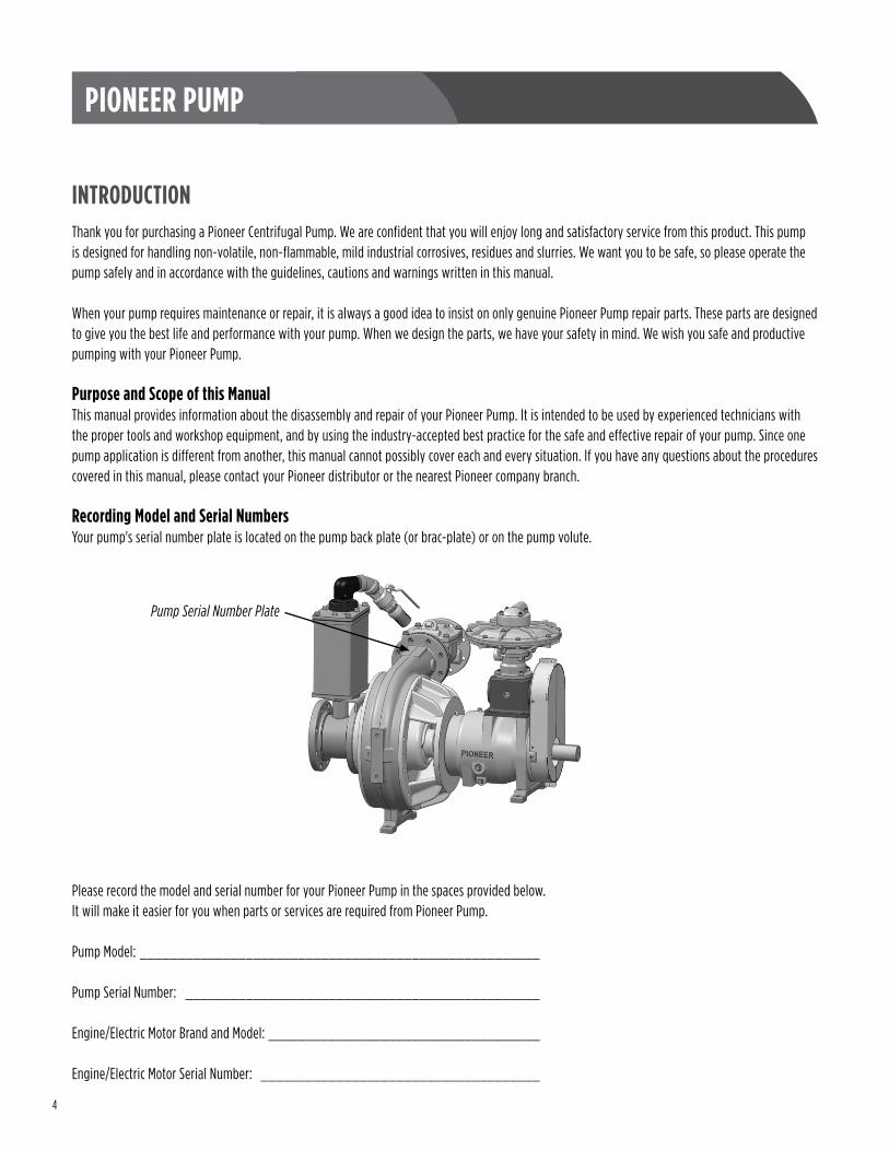
Recording Model and Serial NumbersYour pump's serial number plate is located on the pump back plate (or brac-plate) or on the pump volute .
Please record the model and serial number for your Pioneer Pump in the spaces provided below . It will make it easier for you when parts or services are required from Pioneer Pump .
Pump Model: _____________________________________________________
Pump Serial Number: _______________________________________________
Engine/Electric Motor Brand and Model: ____________________________________
Engine/Electric Motor Serial Number: _____________________________________
Pump Serial Number Plate
5
PIONEER PUMP
WARNING This manual provides installation, operation and maintenance instructions for your Pioneer Pump . It is intended to make your personnel aware of any procedure that requires special attention due to potential hazards to personnel or equipment . Read all instructions carefully, and remember, pump installations are seldom identical . Centrifugal Pumps are designed for specific service and may or may not be suited for any other service without loss of performance or potential damage to equipment or personnel . Therefore, this manual cannot possibly provide detailed instructions and precautions for each specific application . It is the owner/installer’s responsibility to ensure that applications not addressed in this manual are performed only after establishing that neither operator safety nor pump integrity are compromised by the installation . If there is ever any doubt about suitability for a specific purpose, contact Pioneer Pump, Inc . or your Pioneer Pump distributor for assistance .
WARNING Before attempting to service or maintain this pump, read this manual carefully . Operators and maintenance personnel should have a good understanding of all aspects of this pump and the pumping conditions . Failure of operating personnel to be familiar with all aspects of the pump operation outlined in this manual could contribute to equipment damage, bodily injury or possible death .
WARNINGWhen you service your Pioneer Pump, be sure to only use genuine Pioneer Pump parts . These parts are designed to give you the longest wear life and the performance the pump was designed to achieve . We have your safety in mind when we design the parts we use in Pioneer Pumps . If you decide to use other brand parts in your Pioneer Pump, operating safety could be compromised and the Pump’s warranty will be void .
WARNING If this pump is used to handle any hazardous materials that can cause illness, either directly or indirectly, take precautions by wearing approved protective clothing and using appropriate safety equipment . Also, review the section on vacuum pump venting . Use lifting and moving equipment in good repair and with adequate capacity to prevent injuries to personnel or damage to the equipment .
WARNING Any lifting equipment is to be rated for at least five (5) times the weight of the item being lifted . Use only established methods when lifting or moving any heavy components . Attach lifting equipment to the lifting device fitted to the pump . If chains, cables, or slings are wrapped around the pump to lift it, ensure that they are positioned so the load is balanced and they do not damage the pump . The lifting bail on trailer- or skid-mounted units is intended for use in lifting the pump package only . Any other items placed on the pump package during a lift could cause the lifting bail to fail and the pump package to fall, possibly causing property damage, personal injury or death . Suction and discharge hoses and piping must be removed from the pump before lifting .
WARNING Do not operate the pump without guards in place over the rotating parts . Exposed rotating parts can catch clothing, fingers, or tools, causing severe injury to personnel .
6
PIONEER PUMP
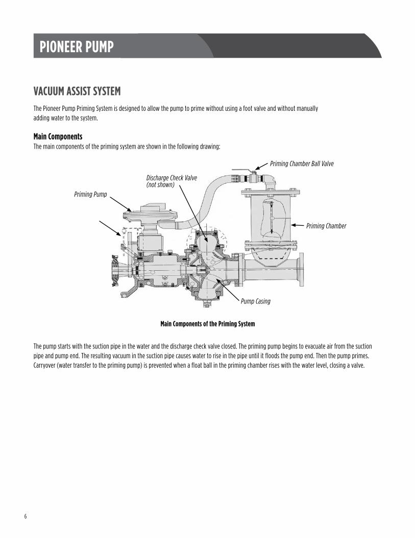
VACUUM ASSIST SYSTEMThe Pioneer Pump Priming System is designed to allow the pump to prime without using a foot valve and without manually adding water to the system .
Main ComponentsThe main components of the priming system are shown in the following drawing:
The pump starts with the suction pipe in the water and the discharge check valve closed . The priming pump begins to evacuate air from the suction pipe and pump end . The resulting vacuum in the suction pipe causes water to rise in the pipe until it floods the pump end . Then the pump primes . Carryover (water transfer to the priming pump) is prevented when a float ball in the priming chamber rises with the water level, closing a valve .
Priming Pump
Priming Chamber Ball Valve
Priming Chamber
Discharge Check Valve(not shown)
Main Components of the Priming System
Pump Casing
7
PIONEER PUMP
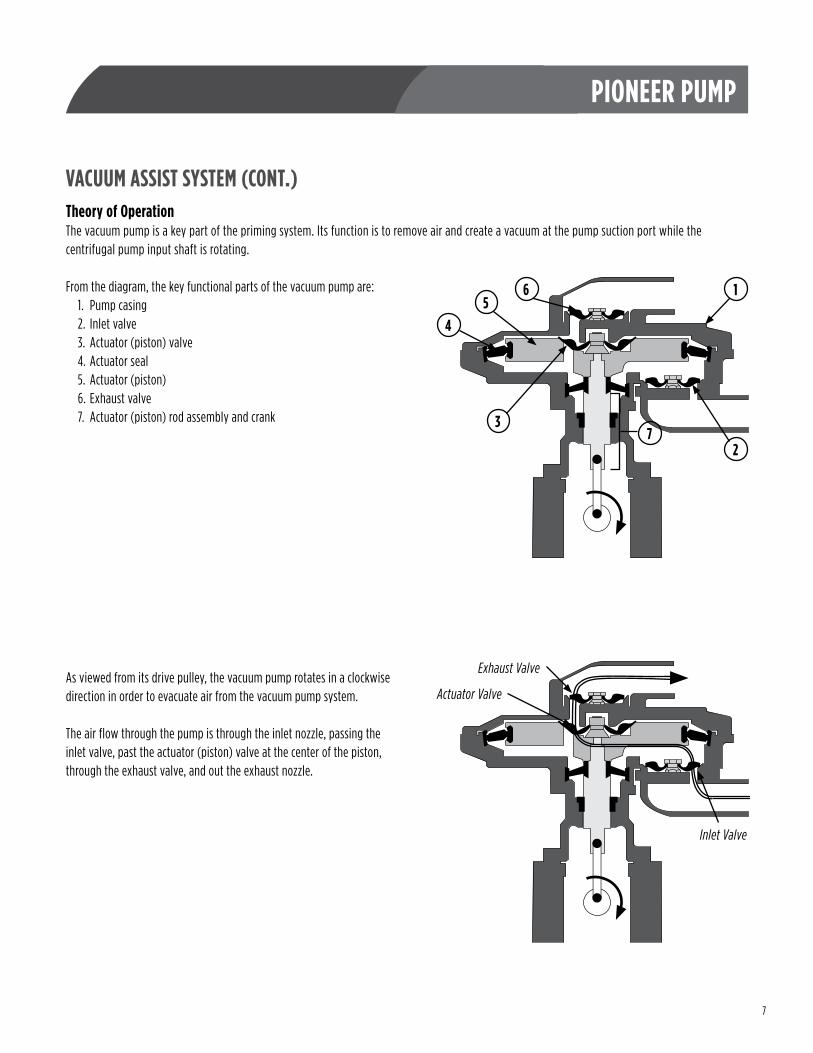
VACUUM ASSIST SYSTEM (CONT.)Theory of OperationThe vacuum pump is a key part of the priming system . Its function is to remove air and create a vacuum at the pump suction port while the centrifugal pump input shaft is rotating .
From the diagram, the key functional parts of the vacuum pump are:1 . Pump casing2 . Inlet valve3 . Actuator (piston) valve4 . Actuator seal5 . Actuator (piston)6 . Exhaust valve7 . Actuator (piston) rod assembly and crank
As viewed from its drive pulley, the vacuum pump rotates in a clockwise direction in order to evacuate air from the vacuum pump system .
The air flow through the pump is through the inlet nozzle, passing the inlet valve, past the actuator (piston) valve at the center of the piston, through the exhaust valve, and out the exhaust nozzle .
165
4
37
2
Inlet Valve
Actuator Valve
Exhaust Valve
8
PIONEER PUMP
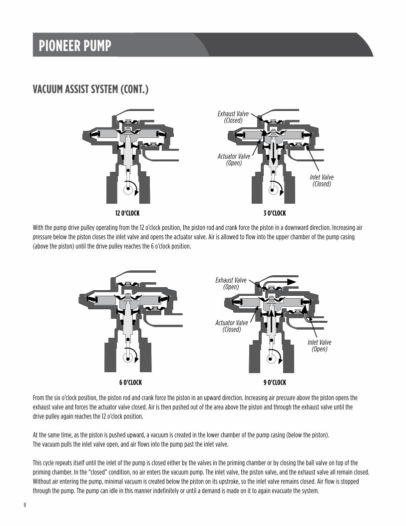
With the pump drive pulley operating from the 12 o’clock position, the piston rod and crank force the piston in a downward direction . Increasing air pressure below the piston closes the inlet valve and opens the actuator valve . Air is allowed to flow into the upper chamber of the pump casing (above the piston) until the drive pulley reaches the 6 o’clock position .
From the six o’clock position, the piston rod and crank force the piston in an upward direction . Increasing air pressure above the piston opens the exhaust valve and forces the actuator valve closed . Air is then pushed out of the area above the piston and through the exhaust valve until the drive pulley again reaches the 12 o’clock position .
At the same time, as the piston is pushed upward, a vacuum is created in the lower chamber of the pump casing (below the piston) . The vacuum pulls the inlet valve open, and air flows into the pump past the inlet valve .
This cycle repeats itself until the inlet of the pump is closed either by the valves in the priming chamber or by closing the ball valve on top of the priming chamber . In the “closed” condition, no air enters the vacuum pump . The inlet valve, the piston valve, and the exhaust valve all remain closed . Without air entering the pump, minimal vacuum is created below the piston on its upstroke, so the inlet valve remains closed . Air flow is stopped through the pump . The pump can idle in this manner indefinitely or until a demand is made on it to again evacuate the system .
VACUUM ASSIST SYSTEM (CONT.)
12 O'CLOCK
Inlet Valve(Closed)
Actuator Valve(Open)
Exhaust Valve(Closed)
3 O'CLOCK
Actuator Valve(Closed)
Exhaust Valve(Open)
Inlet Valve(Open)
9 O'CLOCK6 O'CLOCK
9
PIONEER PUMP
VACUUM ASSIST SYSTEM (CONT.)Pioneer Prime OnlyThe vacuum pump is either top-mounted or side-mounted on Pioneer Prime (PP) series pumps . The pump can be serviced in either configuration, whether mounted to the centrifugal pump or removed .
Removing the Vacuum Pump Drive SystemThe vacuum pump drive system consists of a drive pulley on the main pump drive shaft, a rubber drive belt, and a drive pulley attached to the vacuum pump drive shaft .
• If the vacuum pump is top-mounted, remove the retaining cap screws and remove the adjusting shims to release drive belt tension .• If the vacuum pump is side-mounted, loosen the drive belt adjuster to release drive belt tension .
To remove the pulley on the centrifugal pump drive shaft, first remove the centrifugal pump from the driver, then remove the drive coupling . The drive removal procedure is covered in the “SAE Housing and Coupler” section of this manual .
With the drive coupling removed, the vacuum pump drive pulley can be accessed .
1 . Before removing the pulley, measure and record the distance between the face of the pulley to the end of the shaft . This measurement will be required to position the pulley when reinstalling it .
2 . Remove two set screws in the pulley root .
3 . Remove 1/2" bolt from the two-piece wedged key .
4 . Use a 3/8" threaded bolt to drive the two parts of the two-piece wedged key apart .
5 . Once the key is apart, one half of the key can be removed, and the pulley can be removed from the shaft . Once the pulley is removed, the remaining part of the key can be removed from the shaft .
10
PIONEER PUMP
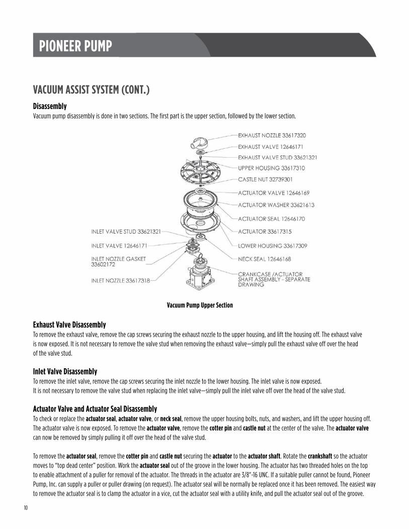
VACUUM ASSIST SYSTEM (CONT.)DisassemblyVacuum pump disassembly is done in two sections . The first part is the upper section, followed by the lower section .
Exhaust Valve DisassemblyTo remove the exhaust valve, remove the cap screws securing the exhaust nozzle to the upper housing, and lift the housing off . The exhaust valve is now exposed . It is not necessary to remove the valve stud when removing the exhaust valve—simply pull the exhaust valve off over the head of the valve stud .
Inlet Valve DisassemblyTo remove the inlet valve, remove the cap screws securing the inlet nozzle to the lower housing . The inlet valve is now exposed . It is not necessary to remove the valve stud when replacing the inlet valve—simply pull the inlet valve off over the head of the valve stud .
Actuator Valve and Actuator Seal DisassemblyTo check or replace the actuator seal, actuator valve, or neck seal, remove the upper housing bolts, nuts, and washers, and lift the upper housing off .The actuator valve is now exposed . To remove the actuator valve, remove the cotter pin and castle nut at the center of the valve . The actuator valve can now be removed by simply pulling it off over the head of the valve stud .
To remove the actuator seal, remove the cotter pin and castle nut securing the actuator to the actuator shaft . Rotate the crankshaft so the actuator moves to “top dead center” position . Work the actuator seal out of the groove in the lower housing . The actuator has two threaded holes on the top to enable attachment of a puller for removal of the actuator . The threads in the actuator are 3/8"-16 UNC . If a suitable puller cannot be found, Pioneer Pump, Inc . can supply a puller or puller drawing (on request) . The actuator seal will be normally be replaced once it has been removed . The easiest way to remove the actuator seal is to clamp the actuator in a vice, cut the actuator seal with a utility knife, and pull the actuator seal out of the groove .
Vacuum Pump Upper Section

11
PIONEER PUMP
Lower Housing and Neck Seal Disassembly
1 . With the actuator removed, remove the nuts and washers from the studs securing the lower housing to the pedestal . Apply a lubricant, such as petroleum jelly, to the exposed portion of the actuator shaft .
2 . Lift the lower housing off the pedestal . The neck seal will remain with the lower housing .
3 . Remove the neck seal from the counterbore in the bottom of the lower housing .
4 . To further disassemble, remove the cap screws securing the pedestal to the crankcase and lift the pedestal off over the actuator shaft . Take care to support the actuator shaft so that it doesn’t become marred or damaged by contact with the crankcase .
5 . Rotate the crankshaft to bring the actuator shaft to its top dead center position .
6 . Remove one of the retaining rings at one end of the fulcrum pin . Remove the fulcrum pin, the connecting rod small-end bearings, and the actuator shaft bearing . Slide the connecting rod as far to one side of the crankshaft as possible . With a pair of pliers, remove the oil flinger from the crankshaft .
7 . Remove the bearing cap fasteners from both the drive end and the opposite drive end, then remove the shaft-end bearing cap and opposite shaft-end bearing cap . Push the crankshaft far enough out the opposite drive end to access the bearing locknut . Remove the bearing locknut and bearing washer .
8 . The crankshaft can now be pulled out of the drive end of the crankcase . The opposite drive end crankshaft roller bearing should remain in the crankcase . The drive end crankshaft roller bearing may slide off the crankshaft by hand or may have to be removed with a gear puller .
Vacuum Pump Lower Section
VACUUM ASSIST SYSTEM (CONT.)
12
PIONEER PUMP
VACUUM ASSIST SYSTEM (CONT.)Lower Housing and Neck Seal Disassembly (Cont.)
9 . The connecting rod can now be lifted out of the top of the crankcase . Inspect the connecting rod small-end bearings for uneven or excessive wear . If the inside diameter of the installed connecting rod small-end bearings exceeds 0 .628" (15 .95 mm), the bearings should be replaced .
NOTE! If the connecting rod is to be replaced, the new parts will be complete with new bearings. No further machining or reaming will be required. If only the bearings will be replaced, remove the old bearings . To remove the old bearings, press them out using a suitable mandrel . To install the new bearings, press them in using a suitable mandrel . After the new connecting rod small-end bearings are pressed in, ream them to an inside diameter of 0 .6255" (15 .88 mm) to 0 .6260" (15 .90 mm) .
10 . The actuator shaft bearing should be inspected for uneven or excessive wear . If the inside diameter of the installed actuator shaft bearing exceeds 0 .628" (15 .95 mm), the bearing should be replaced . To remove the old bearing, press it out using a suitable mandrel . To install the new bearing, press it in using a suitable mandrel . After the new actuator shaft bearing has been pressed in, ream it to an inside diameter of 0 .6255" (15 .88 mm) to 0 .6260" (15 .90 mm) .
11 . Inspect the connecting rod large-end bearing for excessive or uneven wear . If the inside diameter exceeds 2 .007" (50 .98 mm), the bearing should be replaced . To remove the old bearing, press it out using a suitable mandrel . To install the new bearing, press it in using a suitable mandrel . Be sure to install the connecting rod large-end bearing with the joint in the bearing aligning to the right or left side of the bore in the connecting rod, not at the top or bottom . This bearing requires no finishing after machining .
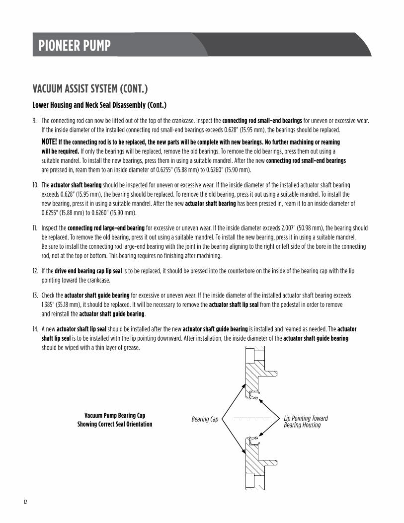
12 . If the drive end bearing cap lip seal is to be replaced, it should be pressed into the counterbore on the inside of the bearing cap with the lip pointing toward the crankcase .
13 . Check the actuator shaft guide bearing for excessive or uneven wear . If the inside diameter of the installed actuator shaft bearing exceeds 1 .385" (35 .18 mm), it should be replaced . It will be necessary to remove the actuator shaft lip seal from the pedestal in order to remove and reinstall the actuator shaft guide bearing .
14 . A new actuator shaft lip seal should be installed after the new actuator shaft guide bearing is installed and reamed as needed . The actuator shaft lip seal is to be installed with the lip pointing downward . After installation, the inside diameter of the actuator shaft guide bearing should be wiped with a thin layer of grease .
Lip Pointing TowardBearing Housing
Bearing CapVacuum Pump Bearing Cap Showing Correct Seal Orientation
13
PIONEER PUMP
VACUUM ASSIST SYSTEM (CONT.)Reassembly
1 . Install the shaft-end ball bearing on the crankshaft . If it does not slide on by hand, heat it uniformly in an oven or on a hot plate to approximately 200 °F (95 °C), then quickly slide it onto the shaft securely up against the shaft shoulder .
WARNING Use proper protective gloves and clothing when handling heated parts!
2 . Hold the connecting rod in the crankcase . Slide the crankshaft assembly through the drive end opening of the crankcase through the connecting rod large-end bearing .
3 . Now slide the opposite drive end bearing onto the crankshaft through the crankcase bore . If it does not slide on by hand, heat it uniformly in an oven or on a hot plate to approximately 200 °F (95 °C), then quickly slide it onto the shaft securely up against the shaft shoulder .
WARNING Use proper protective gloves and clothing when handling heated parts!
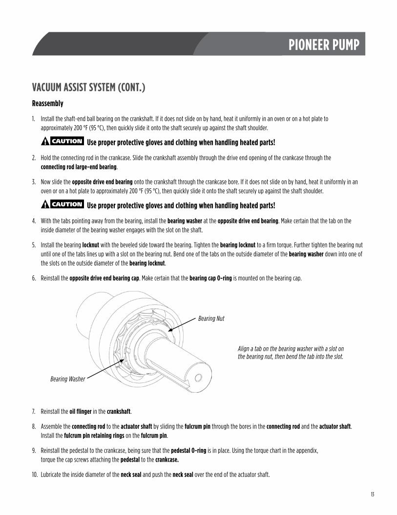
4 . With the tabs pointing away from the bearing, install the bearing washer at the opposite drive end bearing . Make certain that the tab on the inside diameter of the bearing washer engages with the slot on the shaft .
5 . Install the bearing locknut with the beveled side toward the bearing . Tighten the bearing locknut to a firm torque . Further tighten the bearing nut until one of the tabs lines up with a slot on the bearing nut . Bend one of the tabs on the outside diameter of the bearing washer down into one of the slots on the outside diameter of the bearing locknut .
6 . Reinstall the opposite drive end bearing cap . Make certain that the bearing cap O-ring is mounted on the bearing cap .
7 . Reinstall the oil flinger in the crankshaft .
8 . Assemble the connecting rod to the actuator shaft by sliding the fulcrum pin through the bores in the connecting rod and the actuator shaft . Install the fulcrum pin retaining rings on the fulcrum pin .
9 . Reinstall the pedestal to the crankcase, being sure that the pedestal O-ring is in place . Using the torque chart in the appendix, torque the cap screws attaching the pedestal to the crankcase.
10 . Lubricate the inside diameter of the neck seal and push the neck seal over the end of the actuator shaft .
Bearing Washer
Bearing Nut
Align a tab on the bearing washer with a slot on the bearing nut, then bend the tab into the slot.
14
PIONEER PUMP
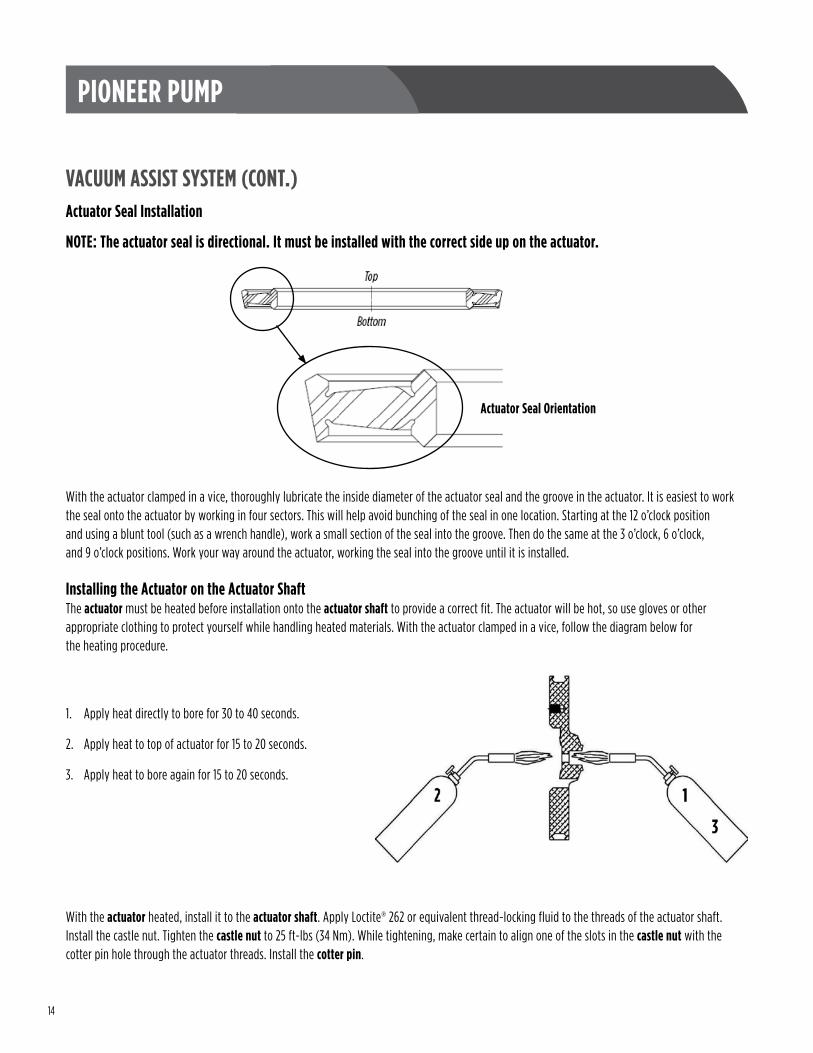
VACUUM ASSIST SYSTEM (CONT.)Actuator Seal Installation
NOTE: The actuator seal is directional. It must be installed with the correct side up on the actuator.
With the actuator clamped in a vice, thoroughly lubricate the inside diameter of the actuator seal and the groove in the actuator . It is easiest to work the seal onto the actuator by working in four sectors . This will help avoid bunching of the seal in one location . Starting at the 12 o’clock position and using a blunt tool (such as a wrench handle), work a small section of the seal into the groove . Then do the same at the 3 o’clock, 6 o’clock, and 9 o’clock positions . Work your way around the actuator, working the seal into the groove until it is installed .
Installing the Actuator on the Actuator ShaftThe actuator must be heated before installation onto the actuator shaft to provide a correct fit . The actuator will be hot, so use gloves or other appropriate clothing to protect yourself while handling heated materials . With the actuator clamped in a vice, follow the diagram below for the heating procedure .
1 . Apply heat directly to bore for 30 to 40 seconds .
2 . Apply heat to top of actuator for 15 to 20 seconds .
3 . Apply heat to bore again for 15 to 20 seconds .
With the actuator heated, install it to the actuator shaft . Apply Loctite® 262 or equivalent thread-locking fluid to the threads of the actuator shaft . Install the castle nut . Tighten the castle nut to 25 ft-lbs (34 Nm) . While tightening, make certain to align one of the slots in the castle nut with the cotter pin hole through the actuator threads . Install the cotter pin .
Actuator Seal Orientation
15
PIONEER PUMP
VACUUM ASSIST SYSTEM (CONT.)Inlet Valve AssemblyWhen installing a new exhaust valve, lubricate the head of the valve stud and push the exhaust valve on over the head of the valve stud . When reattaching the inlet nozzle/valve carrier, check the condition of the inlet nozzle/valve carrier gasket and replace as necessary .
Actuator Valve AssemblyWhen installing a new actuator valve, lubricate the head of the valve stud and push the actuator valve over the head of the valve stud . Apply thread-locking fluid (Loctite® or similar) to the threads . Reinstall the castle nut, tightening the nut to 25 ft-lbs (34 Nm) . Reinstall the cotter pin .
Upper Housing AssemblyInstall the upper housing . There are two versions of the upper housing:
Earlier versions used a blind hole arrangement for securing the aluminum upper housing to the aluminum lower housing . In this case, tighten the cap screws using the aluminum torque chart in the appendix . DO NOT OVERTIGHTEN the cap screws or the threads in the aluminum housing may be damaged .
Recent versions have a through hole with a cap screw and nut arrangement . For this version, the cap screw and nut should be tightened according to the torque chart for steel in the appendix .
Exhaust Valve AssemblyWhen installing a new exhaust valve, lubricate the head of the valve stud and push the exhaust valve on over the head of the valve stud . Reattach the exhaust nozzle to the upper housing . Snug the screws using the aluminum torque chart in the appendix, but do not overtighten, as the threads in the aluminum housing may be damaged .
16
PIONEER PUMP
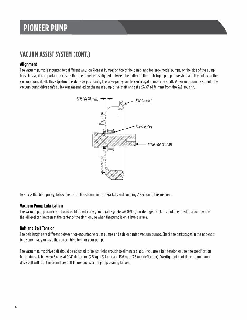
VACUUM ASSIST SYSTEM (CONT.)AlignmentThe vacuum pump is mounted two different ways on Pioneer Pumps: on top of the pump, and for large model pumps, on the side of the pump . In each case, it is important to ensure that the drive belt is aligned between the pulley on the centrifugal pump drive shaft and the pulley on the vacuum pump itself . This adjustment is done by positioning the drive pulley on the centrifugal pump drive shaft . When your pump was built, the vacuum pump drive shaft pulley was assembled on the main pump drive shaft and set at 3/16" (4 .76 mm) from the SAE housing .
To access the drive pulley, follow the instructions found in the “Brackets and Couplings” section of this manual .
Vacuum Pump LubricationThe vacuum pump crankcase should be filled with any good quality grade SAE30ND (non-detergent) oil . It should be filled to a point where the oil level can be seen at the center of the sight gauge when the pump is on a level surface .
Belt and Belt TensionThe belt lengths are different between top-mounted vacuum pumps and side-mounted vacuum pumps . Check the parts pages in the appendix to be sure that you have the correct drive belt for your pump .
The vacuum pump drive belt should be adjusted to be just tight enough to eliminate slack . If you use a belt tension gauge, the specification for tightness is between 5 .6 lbs at 0 .14" deflection (2 .5 kg at 3 .5 mm and 13 .6 kg at 3 .5 mm deflection) . Overtightening of the vacuum pump drive belt will result in premature belt failure and vacuum pump bearing failure .
Drive End of Shaft
Small Pulley
SAE Bracket3/16" (4.76 mm)
17
PIONEER PUMP
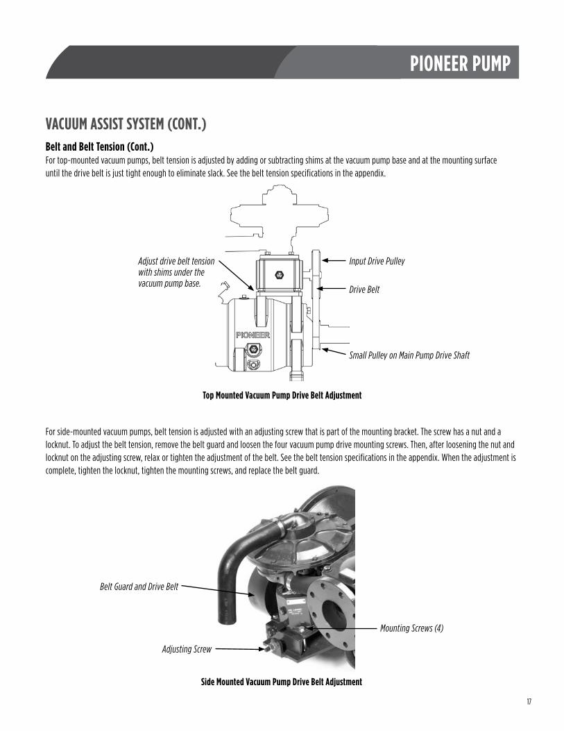
VACUUM ASSIST SYSTEM (CONT.)Belt and Belt Tension (Cont.)For top-mounted vacuum pumps, belt tension is adjusted by adding or subtracting shims at the vacuum pump base and at the mounting surface until the drive belt is just tight enough to eliminate slack . See the belt tension specifications in the appendix .
For side-mounted vacuum pumps, belt tension is adjusted with an adjusting screw that is part of the mounting bracket . The screw has a nut and a locknut . To adjust the belt tension, remove the belt guard and loosen the four vacuum pump drive mounting screws . Then, after loosening the nut and locknut on the adjusting screw, relax or tighten the adjustment of the belt . See the belt tension specifications in the appendix . When the adjustment is complete, tighten the locknut, tighten the mounting screws, and replace the belt guard .
Adjust drive belt tension with shims under the vacuum pump base.
Input Drive Pulley
Drive Belt
Small Pulley on Main Pump Drive Shaft
Top Mounted Vacuum Pump Drive Belt Adjustment
Side Mounted Vacuum Pump Drive Belt Adjustment
Mounting Screws (4)
Belt Guard and Drive Belt
Adjusting Screw
18
PIONEER PUMP
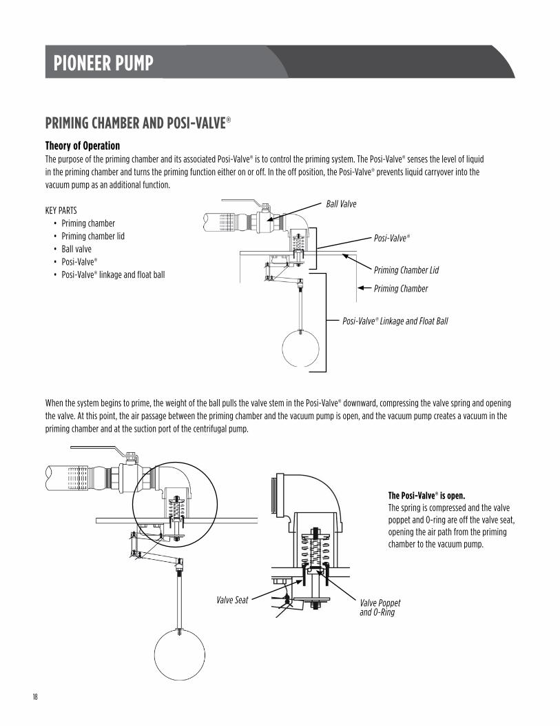
PRIMING CHAMBER AND POSI-VALVE®Theory of OperationThe purpose of the priming chamber and its associated Posi-Valve® is to control the priming system . The Posi-Valve® senses the level of liquid in the priming chamber and turns the priming function either on or off . In the off position, the Posi-Valve® prevents liquid carryover into the vacuum pump as an additional function .
KEY PARTS• Priming chamber• Priming chamber lid• Ball valve• Posi-Valve®• Posi-Valve® linkage and float ball
When the system begins to prime, the weight of the ball pulls the valve stem in the Posi-Valve® downward, compressing the valve spring and opening the valve . At this point, the air passage between the priming chamber and the vacuum pump is open, and the vacuum pump creates a vacuum in the priming chamber and at the suction port of the centrifugal pump .
Ball Valve
Posi-Valve®
Priming Chamber Lid
Priming Chamber
Posi-Valve® Linkage and Float Ball
The Posi-Valve® is open. The spring is compressed and the valve poppet and O-ring are off the valve seat, opening the air path from the priming chamber to the vacuum pump .
Valve Seat Valve Poppet and O-Ring
19
PIONEER PUMP
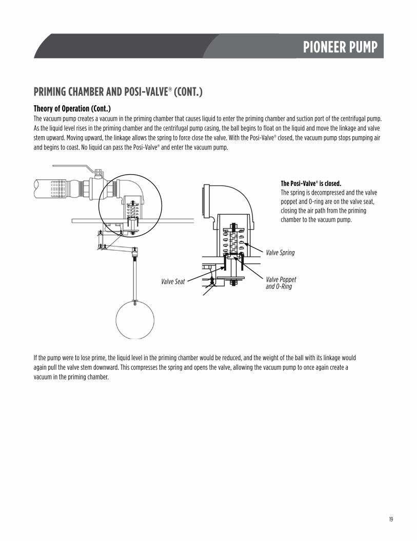
PRIMING CHAMBER AND POSI-VALVE® (CONT.)Theory of Operation (Cont.)The vacuum pump creates a vacuum in the priming chamber that causes liquid to enter the priming chamber and suction port of the centrifugal pump . As the liquid level rises in the priming chamber and the centrifugal pump casing, the ball begins to float on the liquid and move the linkage and valve stem upward . Moving upward, the linkage allows the spring to force close the valve . With the Posi-Valve® closed, the vacuum pump stops pumping air and begins to coast . No liquid can pass the Posi-Valve® and enter the vacuum pump .
If the pump were to lose prime, the liquid level in the priming chamber would be reduced, and the weight of the ball with its linkage would again pull the valve stem downward . This compresses the spring and opens the valve, allowing the vacuum pump to once again create a vacuum in the priming chamber .
The Posi-Valve® is closed. The spring is decompressed and the valve poppet and O-ring are on the valve seat, closing the air path from the priming chamber to the vacuum pump .
Valve Seat Valve Poppet and O-Ring
Valve Spring
20
PIONEER PUMP
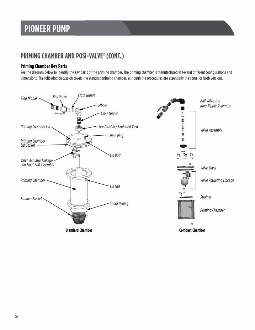
PRIMING CHAMBER AND POSI-VALVE® (CONT.)Priming Chamber Key PartsSee the diagram below to identify the key parts of the priming chamber . The priming chamber is manufactured in several different configurations and dimensions . The following discussion covers the standard priming chamber, although the procedures are essentially the same for both versions .
Valve Assembly
Valve Cover
King Nipple Ball Valve Close Nipple
Elbow
Close Nipple
See Auxiliary Exploded View
Pipe Plug
Valve Actuator Linkage and Float Ball Assembly
Priming Chamber Lid Gasket
Priming Chamber Lid
Lid Bolt
Lid NutPriming Chamber
Spool O-RingStrainer Basket
Priming Chamber
Ball Valve and King Nipple Assembly
Strainer
Valve Actuating Linkage
Compact ChamberStandard Chamber
21
PIONEER PUMP
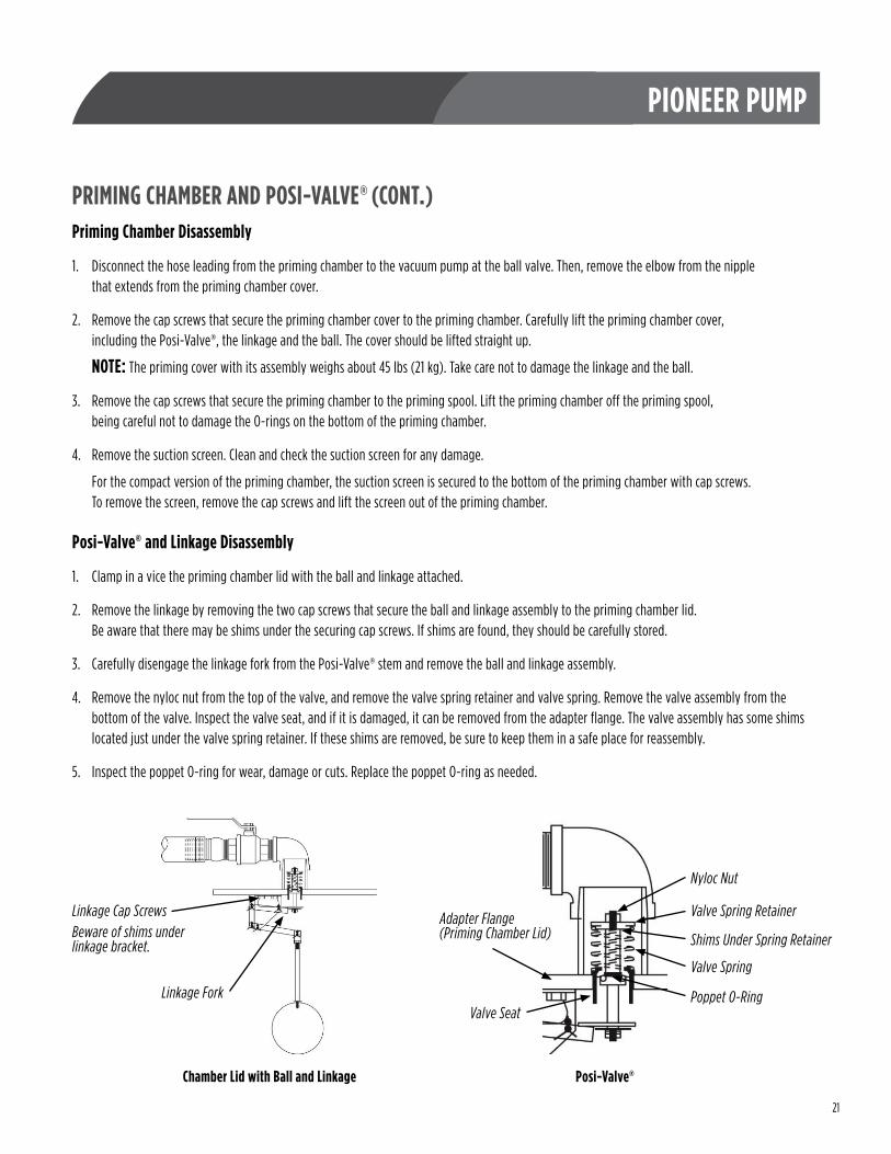
PRIMING CHAMBER AND POSI-VALVE® (CONT.)Priming Chamber Disassembly
1 . Disconnect the hose leading from the priming chamber to the vacuum pump at the ball valve . Then, remove the elbow from the nipple that extends from the priming chamber cover .
2 . Remove the cap screws that secure the priming chamber cover to the priming chamber . Carefully lift the priming chamber cover, including the Posi-Valve®, the linkage and the ball . The cover should be lifted straight up .
NOTE: The priming cover with its assembly weighs about 45 lbs (21 kg) . Take care not to damage the linkage and the ball .
3 . Remove the cap screws that secure the priming chamber to the priming spool . Lift the priming chamber off the priming spool, being careful not to damage the O-rings on the bottom of the priming chamber .
4 . Remove the suction screen . Clean and check the suction screen for any damage .
For the compact version of the priming chamber, the suction screen is secured to the bottom of the priming chamber with cap screws . To remove the screen, remove the cap screws and lift the screen out of the priming chamber .
Posi-Valve® and Linkage Disassembly
1 . Clamp in a vice the priming chamber lid with the ball and linkage attached .
2 . Remove the linkage by removing the two cap screws that secure the ball and linkage assembly to the priming chamber lid . Be aware that there may be shims under the securing cap screws . If shims are found, they should be carefully stored .
3 . Carefully disengage the linkage fork from the Posi-Valve® stem and remove the ball and linkage assembly .
4 . Remove the nyloc nut from the top of the valve, and remove the valve spring retainer and valve spring . Remove the valve assembly from the bottom of the valve . Inspect the valve seat, and if it is damaged, it can be removed from the adapter flange . The valve assembly has some shims located just under the valve spring retainer . If these shims are removed, be sure to keep them in a safe place for reassembly .
5 . Inspect the poppet O-ring for wear, damage or cuts . Replace the poppet O-ring as needed .
Linkage Cap ScrewsBeware of shims under linkage bracket.
Linkage Fork
Chamber Lid with Ball and Linkage Posi-Valve®
Nyloc Nut
Valve Spring Retainer
Shims Under Spring Retainer
Valve Spring
Poppet O-RingValve Seat
Adapter Flange(Priming Chamber Lid)
22
PIONEER PUMP
PRIMING CHAMBER AND POSI-VALVE® (CONT.)Posi-Valve® and Linkage Reassembly
5 . Install the valve seat in the adapter flange . Ensure that the poppet O-ring on the valve stem is installed properly between the two retaining lips on the valve stem .
6 . Insert the valve stem into its location from below the priming chamber cover .
7 . Reinstall the valve spring, the valve shims, and the valve spring retainer from the top of the priming chamber cover .
8 . Secure the Posi-Valve® assembly with its nyloc nut . Tighten the nyloc nut until it is in firm contact with the valve spring retainer .
9 . Reinstall the linkage to the priming chamber cover, making sure that any shims that were removed from the linkage bracket during disassembly are reinstalled .
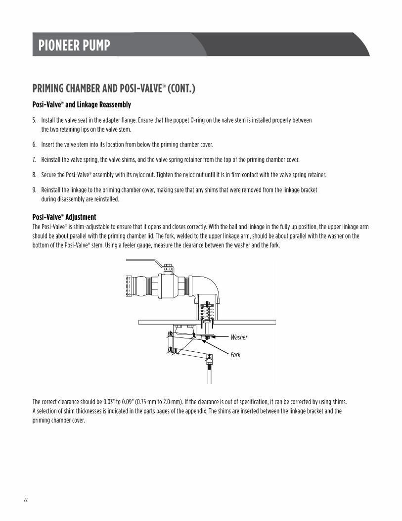
Posi-Valve® AdjustmentThe Posi-Valve® is shim-adjustable to ensure that it opens and closes correctly . With the ball and linkage in the fully up position, the upper linkage arm should be about parallel with the priming chamber lid . The fork, welded to the upper linkage arm, should be about parallel with the washer on the bottom of the Posi-Valve® stem . Using a feeler gauge, measure the clearance between the washer and the fork .
The correct clearance should be 0 .03" to 0 .09" (0 .75 mm to 2 .0 mm) . If the clearance is out of specification, it can be corrected by using shims . A selection of shim thicknesses is indicated in the parts pages of the appendix . The shims are inserted between the linkage bracket and the priming chamber cover .
Fork
Washer
23
PIONEER PUMP
PRIMING CHAMBER AND POSI-VALVE® (CONT.)Priming Chamber Reassembly
1 . Install the suction screen into the priming spool .
NOTE: For the compact version of the priming chamber, install the suction screen in the priming chamber and secure it with cap screws .
2 . There are two O-rings on the bottom of the priming spool . If these O-rings are in any way damaged, nicked, or cut, replace them . A failed or leaking O-ring at this position will allow air into the priming chamber and cause the pump to be slow to prime or not prime at all .
3 . Lubricate the O-rings with a light assembly lubricant and install the priming chamber on the priming spool . Install and tighten the cap screws that secure the priming chamber to the priming spool according to the torque chart in the appendix .
4 . Use a new priming chamber lid gasket and install the priming chamber lid, complete with the Posi-Valve®, the linkage, and the ball . Take care to lower the priming chamber lid assembly straight down into the priming chamber without damaging the linkage and the ball . Note that this assembly weighs about 45 lbs (21 kg) . Use suitable lifting equipment for this assembly .
5 . Install and tighten the priming chamber cover cap screws and nuts according to the torque chart in the appendix .
6 . Attach the hose from the priming pump at the ball valve and tighten the clamp .
24
PIONEER PUMP
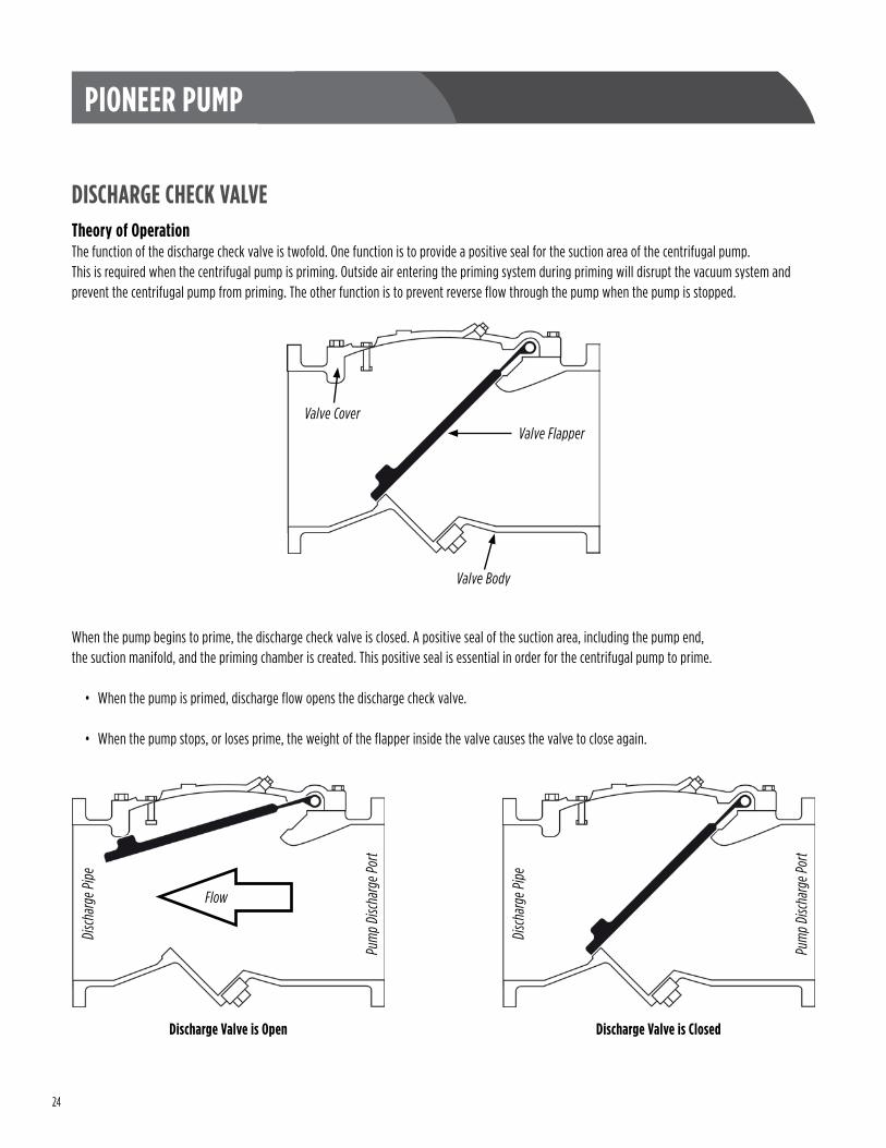
DISCHARGE CHECK VALVETheory of OperationThe function of the discharge check valve is twofold . One function is to provide a positive seal for the suction area of the centrifugal pump . This is required when the centrifugal pump is priming . Outside air entering the priming system during priming will disrupt the vacuum system and prevent the centrifugal pump from priming . The other function is to prevent reverse flow through the pump when the pump is stopped .
When the pump begins to prime, the discharge check valve is closed . A positive seal of the suction area, including the pump end, the suction manifold, and the priming chamber is created . This positive seal is essential in order for the centrifugal pump to prime .
• When the pump is primed, discharge flow opens the discharge check valve .
• When the pump stops, or loses prime, the weight of the flapper inside the valve causes the valve to close again .
Valve Flapper
Valve Body
Valve Cover
Discharge Valve is Closed
Disc
harg
e Pip
e
Pum
p Di
scha
rge P
ort
Discharge Valve is Open
Flow
Pum
p Di
scha
rge P
ort
Disc
harg
e Pip
e
25
PIONEER PUMP
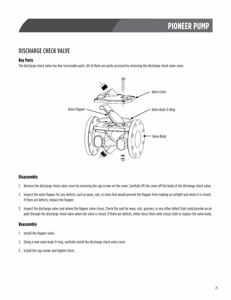
DISCHARGE CHECK VALVEKey PartsThe discharge check valve has few serviceable parts . All of them are easily accessed by removing the discharge check valve cover .
Disassembly
1 . Remove the discharge check valve cover by removing the cap screws on the cover . Carefully lift the cover off the body of the discharge check valve .
2 . Inspect the valve flapper for any defects, such as wear, cuts, or nicks that would prevent the flapper from making an airtight seal when it is closed . If there are defects, replace the flapper .
3 . Inspect the discharge valve seat where the flapper valve closes . Check the seat for wear, cuts, grooves, or any other defect that could provide an air path through the discharge check valve when the valve is closed . If there are defects, either dress them with crocus cloth or replace the valve body .
Reassembly
1 . Install the flapper valve .
2 . Using a new valve body O-ring, carefully install the discharge check valve cover .
3 . Install the cap screws and tighten them .
Valve Cover
Valve Flapper
Valve Body
Valve Body O-Ring
26
PIONEER PUMP
SAE HOUSING AND COUPLERSAE Bracket (Engine Mount) CouplingThe purpose of the SAE bracket is to provide a rigid connection between the pump and the engine . Pioneer offers the SAE bracket as a pump accessory, either with or without a rubber drive coupling . SAE brackets come in a variety of sizes . The bracket size is determined by the design of the engine to be coupled to the pump . Refer to the engine specification sheet or directly to the engine manufacturer to identify the SAE bracket size on your pump . Alternately, refer to the appendix of this manual, where there is a chart of SAE sizes and dimensions .
Pioneer often provides a rubber drive with the SAE bracket . The purpose of the drive is to provide alignment between the pump and the engine and to dampen engine vibration transmitted through the engine crankshaft . The SAE housings and rubber drives provided by Pioneer are self-aligning . There is no need to align the pump and the engine during disassembly or reassembly .
DisassemblyBefore removing any bolts or fasteners, ensure that the pump and engine are both independently supported and that any lifting equipment used is within limits and in good operating condition .
1 . Remove the cap screws that secure the SAE housing to the engine, and separate the engine from the pump .
2 . Remove two set screws on the swedge drive coupling .
3 . Insert one set screw into the threaded hole on the swedge drive coupling to press the swedge drive coupling and rubber drive apart .
4 . Slide the swedge coupling from the drive shaft .
5 . Remove the key from the swedge coupling . Note that the key is machined to prevent the swedge coupling from moving when it is installed .
6 . Remove the rubber drive .
7 . For prime assist (PP) versions of this pump, refer to the “Vacuum Pump” section of this manual for instructions on how to remove and reinstall the vacuum pump drive . Standard centrifugal (SC) versions of this pump do not have the vacuum pump drive pulley .
8 . Remove the SAE bracket by removing the eight bolts securing it to the bearing frame . Note that the SAE bracket weighs about 85 lbs (38 kg) . Ensure that appropriate preparations are made for lifting and handling the bracket once removed .
ReassemblyBefore attempting to assemble the SAE bracket to the bearing frame, ensure that any lifting equipment used is within limits and in good operating condition . The SAE Bracket weighs about 85 lbs (38 kg) .
1 . Install the SAE bracket to the bearing frame and tighten the attaching cap screws to the specified torque . Refer to the hardware identification chart and torque chart in the appendix of this manual for cap screw identification and recommended torque for the SAE bracket cap screws .
2 . For prime assist (PP) versions of this pump, refer to the “Vacuum Pump” section of this manual for instructions on how to reinstall the vacuum pump drive . Standard centrifugal (SC) versions of this pump do not have the vacuum pump drive pulley .
27
PIONEER PUMP
SAE HOUSING AND COUPLER (CONT.)Reassembly (Cont.)
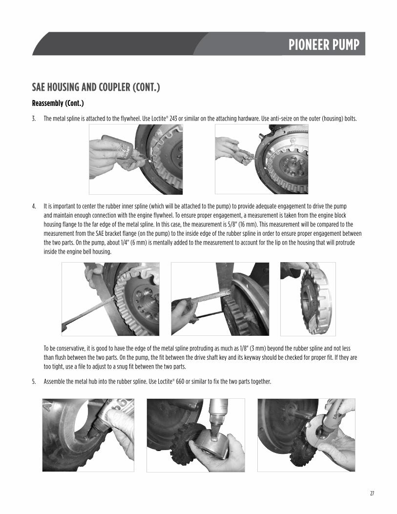
3 . The metal spline is attached to the flywheel . Use Loctite® 243 or similar on the attaching hardware . Use anti-seize on the outer (housing) bolts .
4 . It is important to center the rubber inner spline (which will be attached to the pump) to provide adequate engagement to drive the pump and maintain enough connection with the engine flywheel . To ensure proper engagement, a measurement is taken from the engine block housing flange to the far edge of the metal spline . In this case, the measurement is 5/8" (16 mm) . This measurement will be compared to the measurement from the SAE bracket flange (on the pump) to the inside edge of the rubber spline in order to ensure proper engagement between the two parts . On the pump, about 1/4" (6 mm) is mentally added to the measurement to account for the lip on the housing that will protrude inside the engine bell housing .
To be conservative, it is good to have the edge of the metal spline protruding as much as 1/8" (3 mm) beyond the rubber spline and not less than flush between the two parts . On the pump, the fit between the drive shaft key and its keyway should be checked for proper fit . If they are too tight, use a file to adjust to a snug fit between the two parts .
5 . Assemble the metal hub into the rubber spline . Use Loctite® 660 or similar to fix the two parts together .
28
PIONEER PUMP
SAE HOUSING AND COUPLER (CONT.)Reassembly (Cont.)
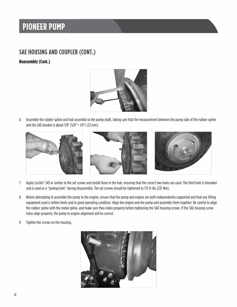
6 . Assemble the rubber spline and hub assembly to the pump shaft, taking care that the measurement between the pump side of the rubber spline and the SAE bracket is about 7/8" (5/8" + 1/4") (23 mm) .
7 . Apply Loctite® 243 or similar to the set screws and install them in the hub, ensuring that the correct two holes are used . The third hole is threaded and is used as a “jacking hole” during disassembly . The set screws should be tightened to 175 ft-lbs (237 Nm) .
8 . Before attempting to assemble the pump to the engine, ensure that the pump and engine are both independently supported and that any lifting equipment used is within limits and in good operating condition . Align the engine and the pump and assemble them together . Be careful to align the rubber spline with the metal spline, and make sure they index properly before tightening the SAE housing screws . If the SAE housing screw holes align properly, the pump to engine alignment will be correct .
9 . Tighten the screws on the housing .
29
PIONEER PUMP
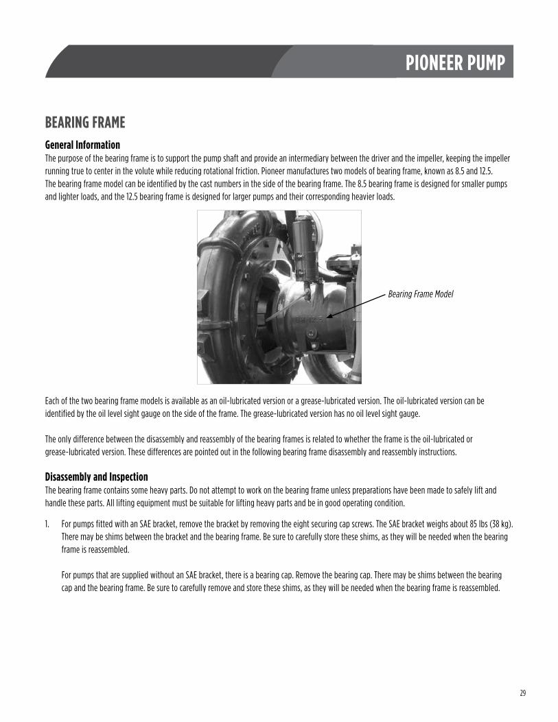
BEARING FRAMEGeneral InformationThe purpose of the bearing frame is to support the pump shaft and provide an intermediary between the driver and the impeller, keeping the impeller running true to center in the volute while reducing rotational friction . Pioneer manufactures two models of bearing frame, known as 8 .5 and 12 .5 . The bearing frame model can be identified by the cast numbers in the side of the bearing frame . The 8 .5 bearing frame is designed for smaller pumps and lighter loads, and the 12 .5 bearing frame is designed for larger pumps and their corresponding heavier loads .
Each of the two bearing frame models is available as an oil-lubricated version or a grease-lubricated version . The oil-lubricated version can be identified by the oil level sight gauge on the side of the frame . The grease-lubricated version has no oil level sight gauge .
The only difference between the disassembly and reassembly of the bearing frames is related to whether the frame is the oil-lubricated or grease-lubricated version . These differences are pointed out in the following bearing frame disassembly and reassembly instructions .
Disassembly and InspectionThe bearing frame contains some heavy parts . Do not attempt to work on the bearing frame unless preparations have been made to safely lift and handle these parts . All lifting equipment must be suitable for lifting heavy parts and be in good operating condition .
1 . For pumps fitted with an SAE bracket, remove the bracket by removing the eight securing cap screws . The SAE bracket weighs about 85 lbs (38 kg) . There may be shims between the bracket and the bearing frame . Be sure to carefully store these shims, as they will be needed when the bearing frame is reassembled . For pumps that are supplied without an SAE bracket, there is a bearing cap . Remove the bearing cap . There may be shims between the bearing cap and the bearing frame . Be sure to carefully remove and store these shims, as they will be needed when the bearing frame is reassembled .
Bearing Frame Model
30
PIONEER PUMP
BEARING FRAME (CONT.)Disassembly and Inspection (Cont.)
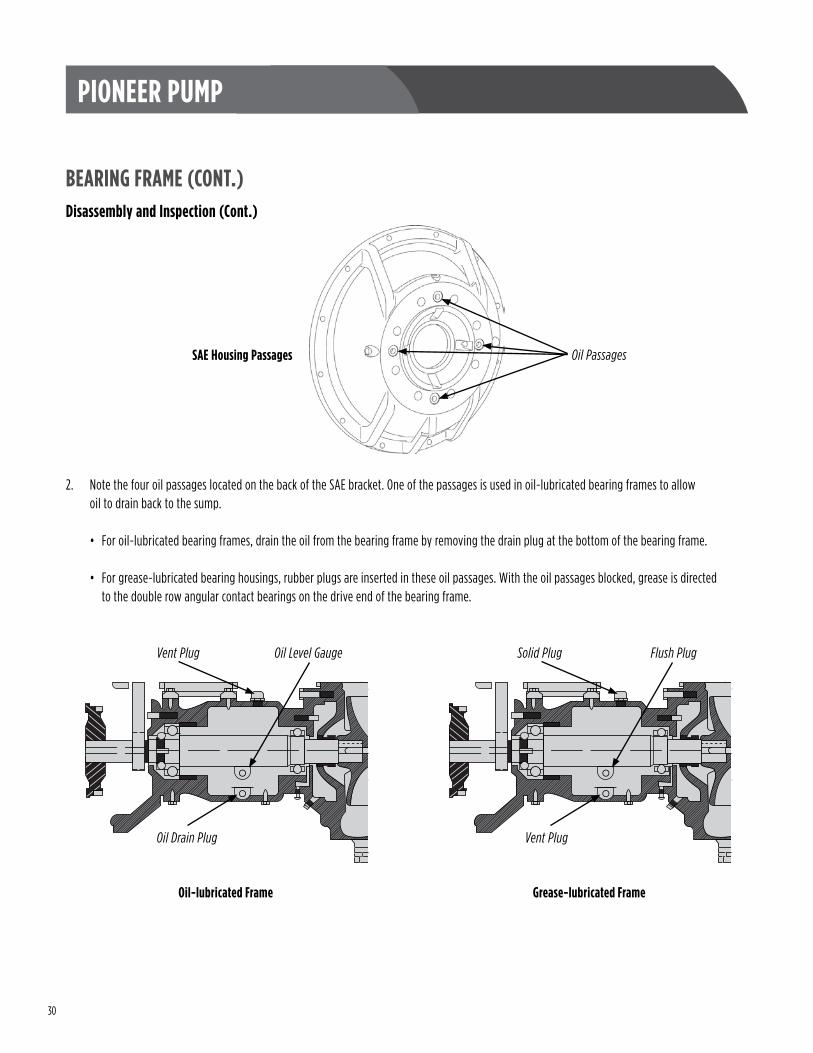
2 . Note the four oil passages located on the back of the SAE bracket . One of the passages is used in oil-lubricated bearing frames to allow oil to drain back to the sump .
• For oil-lubricated bearing frames, drain the oil from the bearing frame by removing the drain plug at the bottom of the bearing frame .
• For grease-lubricated bearing housings, rubber plugs are inserted in these oil passages . With the oil passages blocked, grease is directed to the double row angular contact bearings on the drive end of the bearing frame .
Oil-lubricated Frame
Oil Level GaugeVent Plug
Oil Drain Plug
Grease-lubricated Frame
Flush PlugSolid Plug
Vent Plug
Oil PassagesSAE Housing Passages

31
PIONEER PUMP
BEARING FRAME (CONT.)Disassembly and Inspection (Cont.)
3 . Remove the bearing isolator . Oil-lubricated bearing frames have only one bearing isolator, located at the pump end of the pump shaft . Grease-lubricated bearing frames have two bearing isolators, one located at each end of the pump shaft . The bearing isolators are held in place by O-rings and can be pried out of their bores .
4 . Use a dead blow hammer and firmly tap on the pump end of the shaft to remove the shaft with bearings .
5 . Normally, when the bearings and shaft are removed from the bearing housing, the bearings will be replaced . However, they can be checked, and if found to be okay, may be reused . Check the bearings by rotating them by hand and feel if there is any roughness or excessive wear . If there is roughness, wear, or discoloration, the bearings should be replaced . Check the bearing at the power input end for a snug slip fit and the bearing at the pump end for a tight press fit . Then check the bearings for a snug slip fit in the bearing frame .
If there are any discrepancies, the bearings should be replaced . To remove the pump end bearing, use a standard bearing puller . To remove the power input end bearing, flatten the tab on the retaining washer, then remove the bearing retaining nut . The bearing should be a snug slip fit and should slide off . No puller is normally needed to remove the power end bearing(s) .
If the bearings will be reused, it is essential to protect them from contamination . Wrapping them in clean plastic cling wrap or a clean plastic bag is a good way to store them until they are needed for installation .
6 . With the bearings removed from the pump shaft, inspect the shaft, paying particular attention to the bearing shoulders to ensure that they are clean with no burrs or deformities . The shaft should be straight, free from cracks, dents, or other damage . There should be no metal discoloration or blueing .
7 . Clean and properly store all parts that will be used for reassembling the bearing frame . Cleanliness is a key concern for all of the parts . If using a solvent tank to clean the bearings or other parts, be sure to have adequate ventilation, as most solvents are toxic and inflammable . Follow all precautions pertaining to the solvent and keep the area free from sparks, flame, and excessive heat .
32
PIONEER PUMP
BEARING FRAME (CONT.)ReassemblySafety glasses, welder’s gloves, cut-resistant gloves, and safety boots should be worn before attempting to rebuild the bearing housing . Any lifting equipment used must be suitable and in good working order and condition . Cleanliness of the work area is important in the reassembly process .
1 . Install the pump end bearing on the shaft . Always follow the bearing manufacturer’s instructions when handling and installing the bearing . Before assembly, use either an electrical induction heater or hot plate to preheat the bearing to a uniform temperature . Do not exceed 220 °F (105 °C) . While the bearing is hot and while wearing heat resistant (welder’s) gloves, slide the bearing into position on the shaft . Be sure that the bearing is installed square and is fully seated against the shoulder on the pump shaft .
If a bearing heater is not available, use a suitable sleeve and a hydraulic press to push the bearing on to the shaft . When using the sleeve, be sure to press only against the inner race of the bearing, and be sure that the bearing inner race is seated squarely against the shoulder on the pump shaft .
2 . Pioneer produces two different configurations for the drive end bearing . There is a single bearing design and a double angular contact bearing design . Refer to the parts manual of your pump to confirm which configuration to follow .
The drive end bearing is a firm slide fit on the shaft . It is not necessary to heat the bearing, although it can make the process easier if the bearing(s) are heated before installation on the pump shaft .
• If the pump has only one drive end bearing, the bearing inner race must seat squarely against the shoulder on the pump shaft .
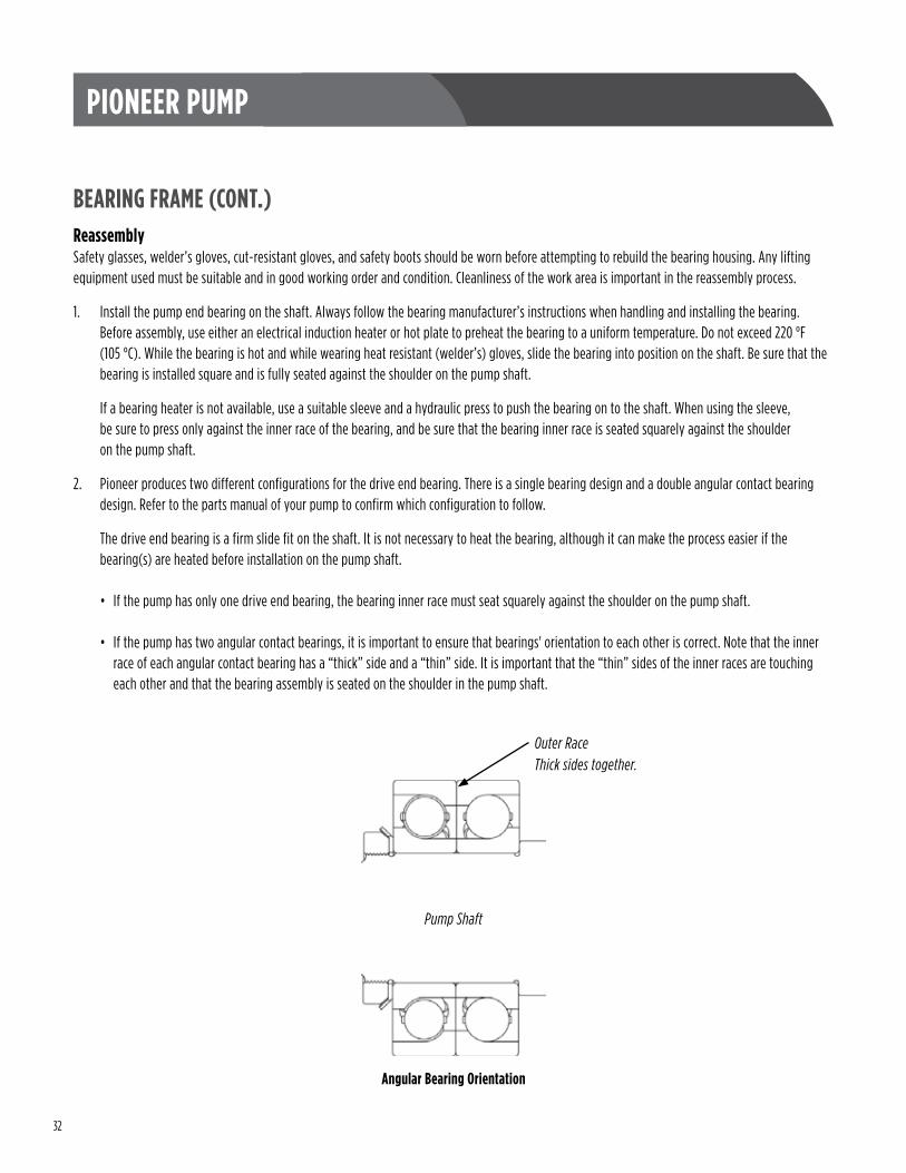
• If the pump has two angular contact bearings, it is important to ensure that bearings' orientation to each other is correct . Note that the inner race of each angular contact bearing has a “thick” side and a “thin” side . It is important that the “thin” sides of the inner races are touching each other and that the bearing assembly is seated on the shoulder in the pump shaft .
Outer RaceThick sides together.
Angular Bearing Orientation
Pump Shaft
33
PIONEER PUMP
BEARING FRAME (CONT.)
Reassembly (Cont.)
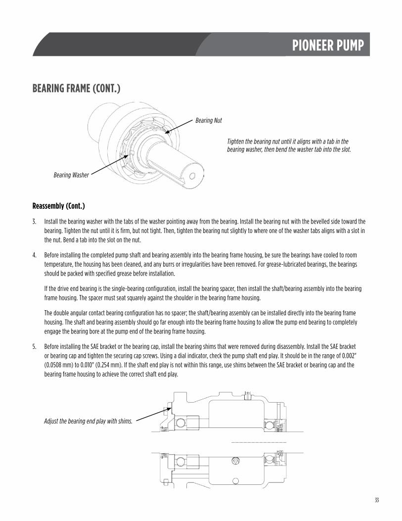
3 . Install the bearing washer with the tabs of the washer pointing away from the bearing . Install the bearing nut with the bevelled side toward the bearing . Tighten the nut until it is firm, but not tight . Then, tighten the bearing nut slightly to where one of the washer tabs aligns with a slot in the nut . Bend a tab into the slot on the nut .
4 . Before installing the completed pump shaft and bearing assembly into the bearing frame housing, be sure the bearings have cooled to room temperature, the housing has been cleaned, and any burrs or irregularities have been removed . For grease-lubricated bearings, the bearings should be packed with specified grease before installation .
If the drive end bearing is the single-bearing configuration, install the bearing spacer, then install the shaft/bearing assembly into the bearing frame housing . The spacer must seat squarely against the shoulder in the bearing frame housing .
The double angular contact bearing configuration has no spacer; the shaft/bearing assembly can be installed directly into the bearing frame housing . The shaft and bearing assembly should go far enough into the bearing frame housing to allow the pump end bearing to completely engage the bearing bore at the pump end of the bearing frame housing .
5 . Before installing the SAE bracket or the bearing cap, install the bearing shims that were removed during disassembly . Install the SAE bracket or bearing cap and tighten the securing cap screws . Using a dial indicator, check the pump shaft end play . It should be in the range of 0 .002" (0 .0508 mm) to 0 .010" (0 .254 mm) . If the shaft end play is not within this range, use shims between the SAE bracket or bearing cap and the bearing frame housing to achieve the correct shaft end play .
Bearing Washer
Bearing Nut
Tighten the bearing nut until it aligns with a tab in the bearing washer, then bend the washer tab into the slot.
Adjust the bearing end play with shims.
34
PIONEER PUMP
BEARING FRAME (CONT.)Reassembly (Cont.)
6 . Once the correct pump shaft end play has been established, install the SAE bracket or bearing cap, making sure initial lubrication has been done as follows:
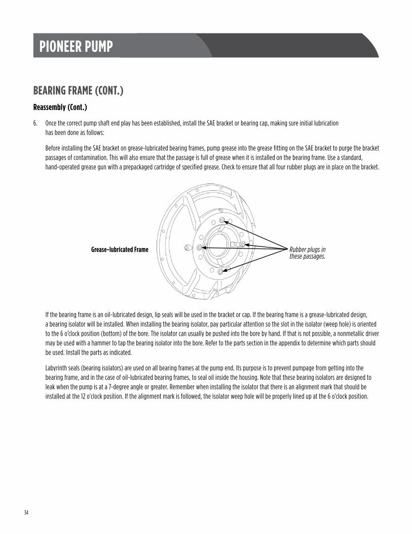
Before installing the SAE bracket on grease-lubricated bearing frames, pump grease into the grease fitting on the SAE bracket to purge the bracket passages of contamination . This will also ensure that the passage is full of grease when it is installed on the bearing frame . Use a standard, hand-operated grease gun with a prepackaged cartridge of specified grease . Check to ensure that all four rubber plugs are in place on the bracket .
If the bearing frame is an oil-lubricated design, lip seals will be used in the bracket or cap . If the bearing frame is a grease-lubricated design, a bearing isolator will be installed . When installing the bearing isolator, pay particular attention so the slot in the isolator (weep hole) is oriented to the 6 o’clock position (bottom) of the bore . The isolator can usually be pushed into the bore by hand . If that is not possible, a nonmetallic driver may be used with a hammer to tap the bearing isolator into the bore . Refer to the parts section in the appendix to determine which parts should be used . Install the parts as indicated .
Labyrinth seals (bearing isolators) are used on all bearing frames at the pump end . Its purpose is to prevent pumpage from getting into the bearing frame, and in the case of oil-lubricated bearing frames, to seal oil inside the housing . Note that these bearing isolators are designed to leak when the pump is at a 7-degree angle or greater . Remember when installing the isolator that there is an alignment mark that should be installed at the 12 o'clock position . If the alignment mark is followed, the isolator weep hole will be properly lined up at the 6 o'clock position .
Rubber plugs in these passages.
Grease-lubricated Frame
35
PIONEER PUMP
PUMP ENDTheory of OperationThe pump end is the part of the pump that does the work of pumping the liquid . In order to execute its function, it must be completely sealed to outside air pressure . Consequently, it contains wear rings, O-rings, a mechanical seal or packing gland, and the pump end casing itself . Also contained in the pump end is the impeller, which spins to add flow energy to the pumped liquid .
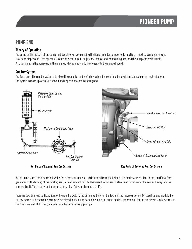
Run Dry SystemThe function of the run dry system is to allow the pump to run indefinitely when it is not primed and without damaging the mechanical seal . The system is made up of an oil reservoir and a special mechanical seal gland .
As the pump starts, the mechanical seal is fed a constant supply of lubricating oil from the inside of the stationary seat . Due to the centrifugal force generated by the turning of the rotating seat, a small amount oil is fed between the two seal surfaces and forced out of the seal and away into the pumped liquid . The oil cools and lubricates the seal surfaces, prolonging seal life .
There are two different configurations of the run dry system . The difference between the two is in the reservoir design . On specific pump models, the run dry system and reservoir is completely enclosed in the pump back plate . On other pump models, the reservoir for the run dry system is external to the pump wet end . Both configurations have the same working principles .
Reservoir Level Gauge, Vent and Fill
Oil Reservoir
Mechanical Seal Gland Area
Special Plastic TubeRun Dry System
Oil Drain
Key Parts of External Run Dry System Key Parts of Enclosed Run Dry System
Run Dry Reservoir Breather
Reservoir Drain (Square Plug)
Reservoir Oil Level Tube
Reservoir Fill Plug
36
PIONEER PUMP
PUMP END (CONT.)Disassembly
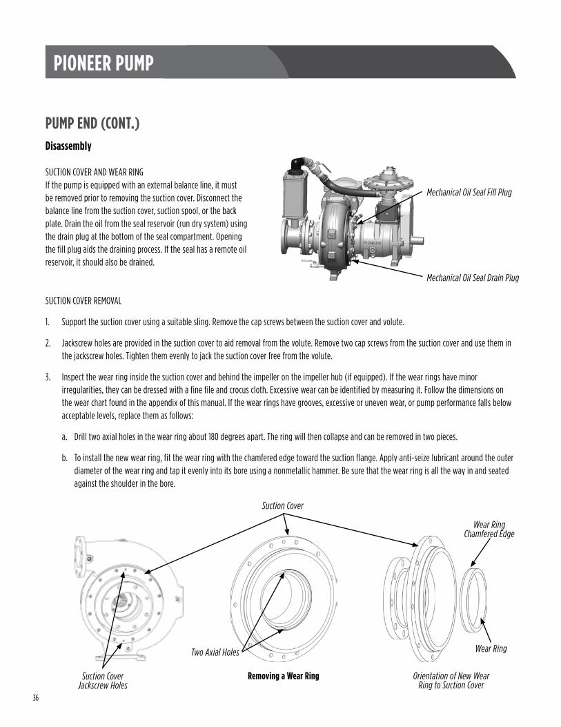
SUCTION COVER AND WEAR RINGIf the pump is equipped with an external balance line, it must be removed prior to removing the suction cover . Disconnect the balance line from the suction cover, suction spool, or the back plate . Drain the oil from the seal reservoir (run dry system) using the drain plug at the bottom of the seal compartment . Opening the fill plug aids the draining process . If the seal has a remote oil reservoir, it should also be drained .
SUCTION COVER REMOVAL
1 . Support the suction cover using a suitable sling . Remove the cap screws between the suction cover and volute .
2 . Jackscrew holes are provided in the suction cover to aid removal from the volute . Remove two cap screws from the suction cover and use them in the jackscrew holes . Tighten them evenly to jack the suction cover free from the volute .
3 . Inspect the wear ring inside the suction cover and behind the impeller on the impeller hub (if equipped) . If the wear rings have minor irregularities, they can be dressed with a fine file and crocus cloth . Excessive wear can be identified by measuring it . Follow the dimensions on the wear chart found in the appendix of this manual . If the wear rings have grooves, excessive or uneven wear, or pump performance falls below acceptable levels, replace them as follows:
a . Drill two axial holes in the wear ring about 180 degrees apart . The ring will then collapse and can be removed in two pieces .
b . To install the new wear ring, fit the wear ring with the chamfered edge toward the suction flange . Apply anti-seize lubricant around the outer diameter of the wear ring and tap it evenly into its bore using a nonmetallic hammer . Be sure that the wear ring is all the way in and seated against the shoulder in the bore .
Suction Cover
Mechanical Oil Seal Drain Plug
Mechanical Oil Seal Fill Plug
Wear Ring
Suction Cover Jackscrew Holes
Two Axial Holes
Wear RingChamfered Edge
Orientation of New Wear Ring to Suction Cover
Removing a Wear Ring
37
PIONEER PUMP
PUMP END (CONT.)Disassembly (Cont.)
IMPELLER REMOVAL
WARNING DO NOT use heat to disassemble.
1 . To remove the impeller, first restrain the impeller or pump shaft . Remove the impeller lock screw and washer . Each time the impeller screw is removed, it should be replaced with a new part . Impeller lockwasher kits are available from Pioneer . If your pump is a solids-handling pump (with impeller back vanes), measure and record the clearance between the impeller and the brackplate shroud . This clearance will be used during reassembly .
2 . With the impeller lock screw and washer removed, use a properly sized gear puller to evenly pry between the back shroud of the impeller and the back plate . As the impeller slides off the pump shaft, be aware of the impeller key, impeller shims, and the mechanical seal spring that will become loose and could fall out . Do not lose any of these parts . They will be needed when the impeller is reinstalled .
3 . Inspect the impeller, looking for signs of uneven wear, cavitation erosion, or other irregularities that could compromise the normal operation or balance of the impeller . Replace the impeller as needed .
RUN DRY SYSTEMThe pump has a mechanical seal run dry system to allow the pump to run indefinitely when it is not primed and without damaging the mechanical seal . Information about the run dry system is discussed earlier in this section .
SEAL REMOVALWith the impeller removed, the mechanical seal is exposed . To remove the mechanical seal, slide the bellows, spring and retainer off the pump shaft as a unit . It is helpful to apply a thin layer of oil to the pump shaft to help free the parts . The stationary seat of the seal remains in the brackplate and can be pressed out of its bore after removing the brackplate . If you plan to reuse the mechanical seal, it is imperative that you take every precaution to protect the seal faces . If the faces are to be cleaned, use electrical contact cleaner and a clean, lint-free cloth . Inspect the seal faces for uneven wear, cracks, or any other irregularities . Replace the seal as needed .
BRACKPLATE REMOVALThe brackplate should be supported by a sling or some other support to prevent it from falling when removed . There are some sensitive parts in the brackplate; they are the stationary seal seat, the brackplate lip seal, and the run dry lip seal . The brackplate can be removed by taking out the screws between the brackplate and the bearing housing . Take care to remove the brackplate straight off the shaft to prevent damaging the sensitive parts in the brackplate . If not already done, the stationary seat of the mechanical seal can be pressed out of its bore .
There are two different configurations of the run dry system . The difference between the two is in the reservoir design . On specific pump models, the run dry system and reservoir are completely enclosed in the pump brackplate . On other pump models, the reservoir for the run dry system is external to the pump wet end . Both configurations have the same working principles .
VOLUTEInspect the volute, looking for excessive or unusual wear and erosion, signs of cavitation, or any other irregularities . Some welding repair to the volute is permissible . Use the proper welding equipment and procedures based on the metallurgy of the volute .
38
PIONEER PUMP
PUMP END (CONT.)ReassemblyThe successful reassembly of the pump end depends on proper tools that are in good condition and a clean workshop environment . The clean environment is particularly important in regard to mechanical seal assembly and installation .
BRACKPLATE TO BEARING HOUSING
1 . Install the brackplate lip seals and the run dry lip seals in the brackplate . Be sure to orient the lip seals correctly, as shown in the drawing .
2 . Apply a coat of oil or grease to the lip seals and slide the brackplate over the pump shaft . Take care to protect the lip seals from cutting or other damage . The brackplate drain port should be located in the 6 o’clock position . Secure the brackplate to the bearing housing using the cap screws removed during disassembly . Follow the hardware torque chart in the appendix to tighten the cap screws . Using a hand-operated grease gun, apply two or three shots of grease between the lip seals .
MECHANICAL SEAL INSTALLATIONCleanliness is the key to success any time you are working with a mechanical seal . Make sure the work area is clean and organized with all of the tools and supplies needed for the job . Use of surgical gloves during this assembly is a good idea .
1 . Use an abrasive cleaning cloth (such as Scotch-Brite™) to clean the surface around the seal location on the brackplate and to break any sharp edges or burrs . A good degreaser or brake cleaner can be used to continue cleaning the seal location . Use a clean, white, lint-free cloth to wipe the area until no more black shows on the cloth .
2 . Inspect the seal gland . Break any sharp or irregular edges and clean the part completely before contemplating assembly . The factory uses an oil additive as assembly grease . Any good light grease or engine oil additive can be used . The grease should NOT contain any silicone .
3 . With the mechanical seal stationary face installed in the seal gland, the seal gland can be installed . The seal face should be cleaned by using electrical contact cleaner (or similar) and wiping it with a lint-free cloth . Touching the seal face with your fingers can damage the seal face, so it is a good idea to wear surgical rubber gloves while installing it .
4 . To install the rotating seal face, first clean the seal face as described earlier . A light coating of ISO 32 oil can be used to coat both seal faces and the pump shaft . Taking care not to cut any O-rings, slide the rotating seat along the pump shaft until it comes into contact with the stationary seat . A soft plastic pipe can be used to gently tap the rotating face into contact with the stationary face .
39
PIONEER PUMP
PUMP END (CONT.)Reassembly (Cont.)
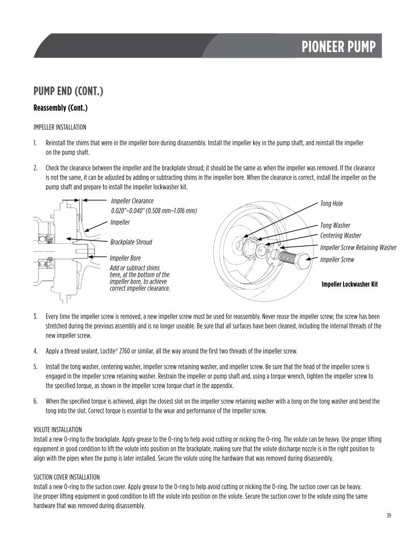
IMPELLER INSTALLATION
1 . Reinstall the shims that were in the impeller bore during disassembly . Install the impeller key in the pump shaft, and reinstall the impeller on the pump shaft .
2 . Check the clearance between the impeller and the brackplate shroud; it should be the same as when the impeller was removed . If the clearance is not the same, it can be adjusted by adding or subtracting shims in the impeller bore . When the clearance is correct, install the impeller on the pump shaft and prepare to install the impeller lockwasher kit .
3 . Every time the impeller screw is removed, a new impeller screw must be used for reassembly . Never reuse the impeller screw; the screw has been stretched during the previous assembly and is no longer useable . Be sure that all surfaces have been cleaned, including the internal threads of the new impeller screw .
4 . Apply a thread sealant, Loctite® 2760 or similar, all the way around the first two threads of the impeller screw .
5 . Install the tong washer, centering washer, impeller screw retaining washer, and impeller screw . Be sure that the head of the impeller screw is engaged in the impeller screw retaining washer . Restrain the impeller or pump shaft and, using a torque wrench, tighten the impeller screw to the specified torque, as shown in the impeller screw torque chart in the appendix .
6 . When the specified torque is achieved, align the closest slot on the impeller screw retaining washer with a tong on the tong washer and bend the tong into the slot . Correct torque is essential to the wear and performance of the impeller screw .
VOLUTE INSTALLATIONInstall a new O-ring to the brackplate . Apply grease to the O-ring to help avoid cutting or nicking the O-ring . The volute can be heavy . Use proper lifting equipment in good condition to lift the volute into position on the brackplate, making sure that the volute discharge nozzle is in the right position to align with the pipes when the pump is later installed . Secure the volute using the hardware that was removed during disassembly .
SUCTION COVER INSTALLATIONInstall a new O-ring to the suction cover . Apply grease to the O-ring to help avoid cutting or nicking the O-ring . The suction cover can be heavy . Use proper lifting equipment in good condition to lift the volute into position on the volute . Secure the suction cover to the volute using the same hardware that was removed during disassembly .
Impeller
Brackplate Shroud
Impeller BoreAdd or subtract shims here, at the bottom of the impeller bore, to achieve correct impeller clearance.
Impeller Clearance0.020"–0.040" (0.508 mm–1.016 mm)
Impeller Lockwasher Kit
Tong Hole
Tong WasherCentering Washer
Impeller Screw Retaining Washer
Impeller Screw
40
PIONEER PUMP
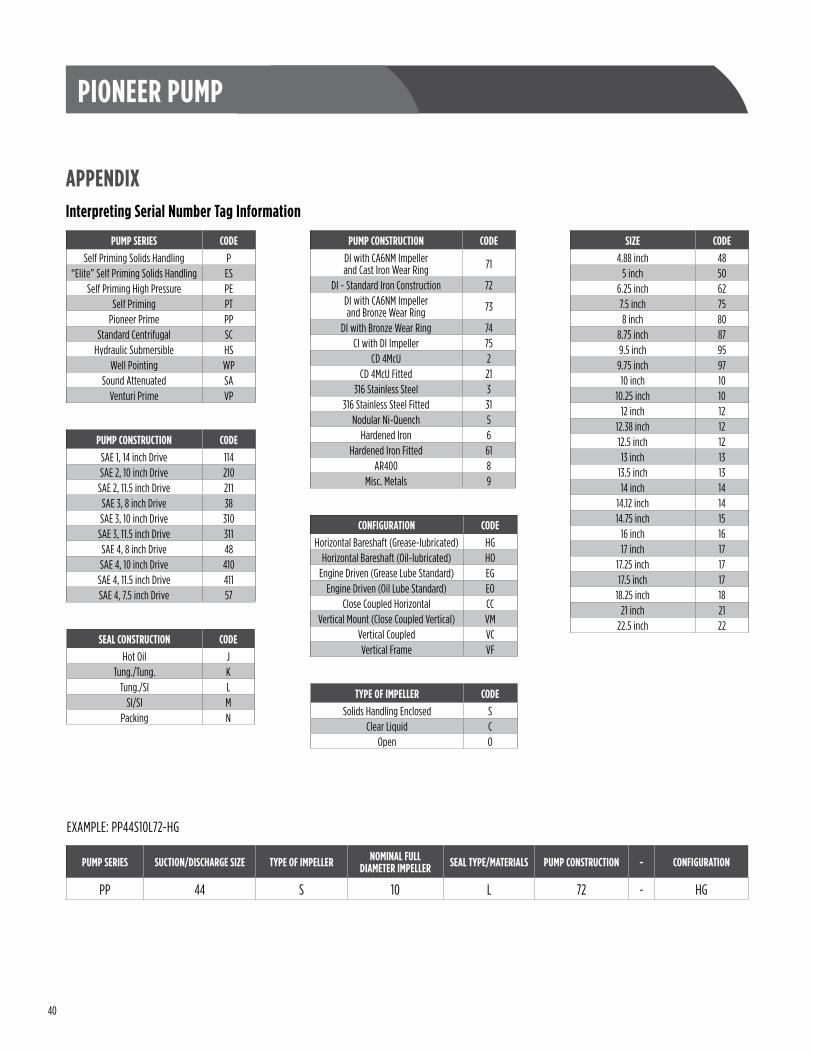
APPENDIXInterpreting Serial Number Tag Information
PUMP CONSTRUCTION CODEDI with CA6NM Impeller and Cast Iron Wear Ring 71
DI - Standard Iron Construction 72DI with CA6NM Impeller and Bronze Wear Ring 73
DI with Bronze Wear Ring 74CI with DI Impeller 75
CD 4McU 2CD 4McU Fitted 21
316 Stainless Steel 3316 Stainless Steel Fitted 31
Nodular Ni-Quench 5Hardened Iron 6
Hardened Iron Fitted 61AR400 8
Misc . Metals 9
PUMP SERIES CODESelf Priming Solids Handling P
“Elite” Self Priming Solids Handling ESSelf Priming High Pressure PE
Self Priming PTPioneer Prime PP
Standard Centrifugal SCHydraulic Submersible HS
Well Pointing WPSound Attenuated SA
Venturi Prime VP
CONFIGURATION CODEHorizontal Bareshaft (Grease-lubricated) HG
Horizontal Bareshaft (Oil-lubricated) HOEngine Driven (Grease Lube Standard) EG
Engine Driven (Oil Lube Standard) EOClose Coupled Horizontal CC
Vertical Mount (Close Coupled Vertical) VMVertical Coupled VCVertical Frame VF
SEAL CONSTRUCTION CODEHot Oil J
Tung ./Tung . KTung ./SI L
SI/SI MPacking N
TYPE OF IMPELLER CODESolids Handling Enclosed S
Clear Liquid COpen O
PUMP CONSTRUCTION CODESAE 1, 14 inch Drive 114SAE 2, 10 inch Drive 210
SAE 2, 11 .5 inch Drive 211SAE 3, 8 inch Drive 38SAE 3, 10 inch Drive 310
SAE 3, 11 .5 inch Drive 311SAE 4, 8 inch Drive 48SAE 4, 10 inch Drive 410
SAE 4, 11 .5 inch Drive 411SAE 4, 7 .5 inch Drive 57
EXAMPLE: PP44S10L72-HG
PUMP SERIES SUCTION/DISCHARGE SIZE TYPE OF IMPELLER NOMINAL FULL DIAMETER IMPELLER SEAL TYPE/MATERIALS PUMP CONSTRUCTION - CONFIGURATION
PP 44 S 10 L 72 - HG
SIZE CODE4 .88 inch 48
5 inch 506 .25 inch 627 .5 inch 758 inch 80
8 .75 inch 879 .5 inch 959 .75 inch 9710 inch 10
10 .25 inch 1012 inch 12
12 .38 inch 1212 .5 inch 1213 inch 13
13 .5 inch 1314 inch 14
14 .12 inch 1414 .75 inch 15
16 inch 1617 inch 17
17 .25 inch 1717 .5 inch 17
18 .25 inch 1821 inch 21
22 .5 inch 22
41
PIONEER PUMP
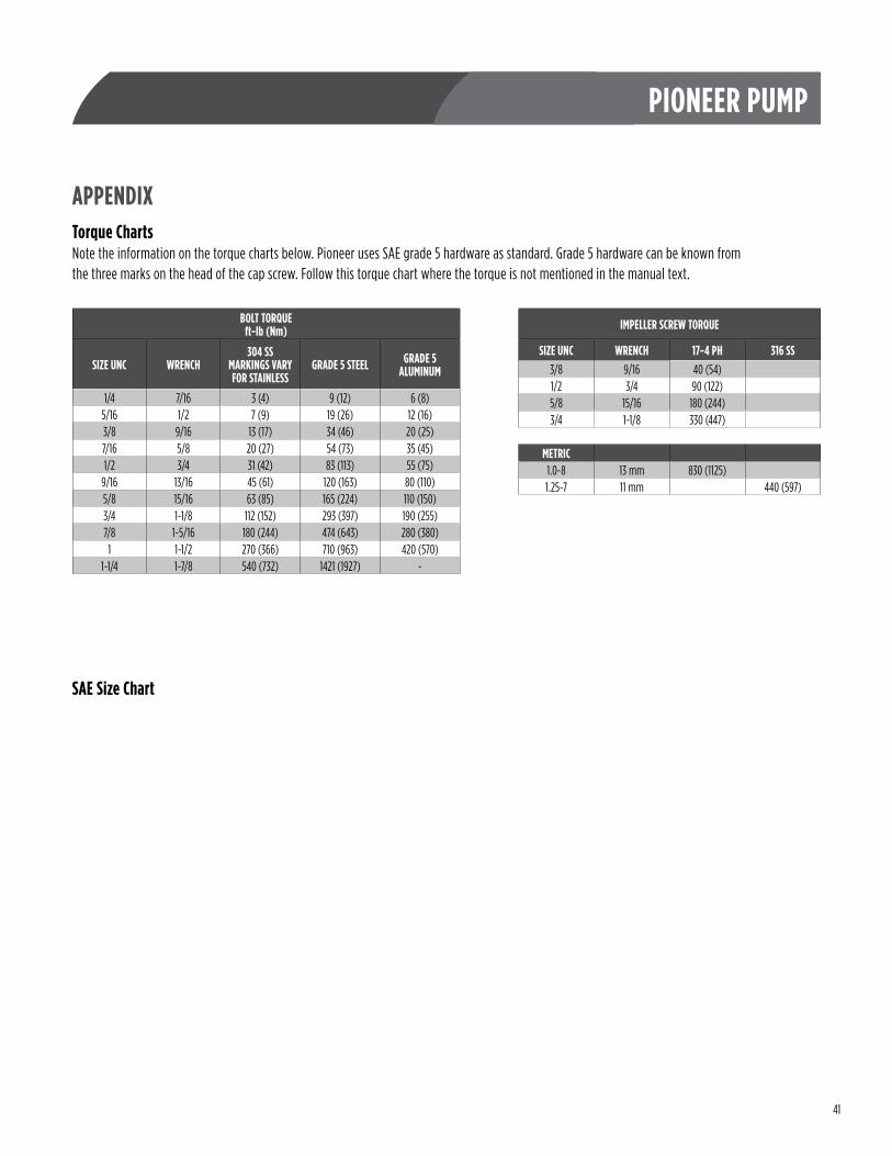
APPENDIXTorque ChartsNote the information on the torque charts below . Pioneer uses SAE grade 5 hardware as standard . Grade 5 hardware can be known from the three marks on the head of the cap screw . Follow this torque chart where the torque is not mentioned in the manual text .
BOLT TORQUEft-lb (Nm)
SIZE UNC WRENCH304 SS
MARKINGS VARY FOR STAINLESS
GRADE 5 STEEL GRADE 5 ALUMINUM
1/4 7/16 3 (4) 9 (12) 6 (8)5/16 1/2 7 (9) 19 (26) 12 (16)3/8 9/16 13 (17) 34 (46) 20 (25)7/16 5/8 20 (27) 54 (73) 35 (45)1/2 3/4 31 (42) 83 (113) 55 (75)
9/16 13/16 45 (61) 120 (163) 80 (110)5/8 15/16 63 (85) 165 (224) 110 (150)3/4 1-1/8 112 (152) 293 (397) 190 (255)7/8 1-5/16 180 (244) 474 (643) 280 (380)
1 1-1/2 270 (366) 710 (963) 420 (570)1-1/4 1-7/8 540 (732) 1421 (1927) -
IMPELLER SCREW TORQUE
SIZE UNC WRENCH 17-4 PH 316 SS3/8 9/16 40 (54)1/2 3/4 90 (122)5/8 15/16 180 (244)3/4 1-1/8 330 (447)
METRIC1 .0-8 13 mm 830 (1125)1 .25-7 11 mm 440 (597)
SAE Size Chart
42
PIONEER PUMP
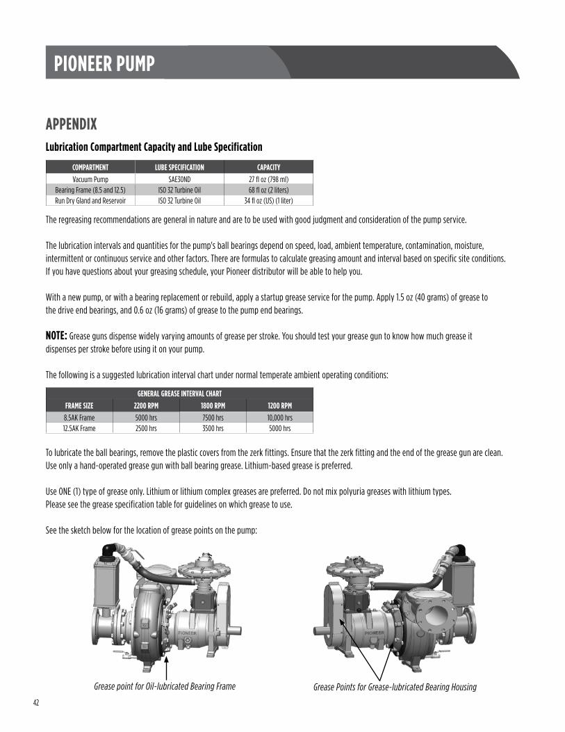
APPENDIXLubrication Compartment Capacity and Lube Specification
COMPARTMENT LUBE SPECIFICATION CAPACITYVacuum Pump SAE30ND 27 fl oz (798 ml)
Bearing Frame (8 .5 and 12 .5) ISO 32 Turbine Oil 68 fl oz (2 liters)Run Dry Gland and Reservoir ISO 32 Turbine Oil 34 fl oz (US) (1 liter)
The regreasing recommendations are general in nature and are to be used with good judgment and consideration of the pump service .
The lubrication intervals and quantities for the pump's ball bearings depend on speed, load, ambient temperature, contamination, moisture, intermittent or continuous service and other factors . There are formulas to calculate greasing amount and interval based on specific site conditions . If you have questions about your greasing schedule, your Pioneer distributor will be able to help you .
With a new pump, or with a bearing replacement or rebuild, apply a startup grease service for the pump . Apply 1 .5 oz (40 grams) of grease to the drive end bearings, and 0 .6 oz (16 grams) of grease to the pump end bearings .
NOTE: Grease guns dispense widely varying amounts of grease per stroke . You should test your grease gun to know how much grease it dispenses per stroke before using it on your pump .
The following is a suggested lubrication interval chart under normal temperate ambient operating conditions:
To lubricate the ball bearings, remove the plastic covers from the zerk fittings . Ensure that the zerk fitting and the end of the grease gun are clean . Use only a hand-operated grease gun with ball bearing grease . Lithium-based grease is preferred .
Use ONE (1) type of grease only . Lithium or lithium complex greases are preferred . Do not mix polyuria greases with lithium types . Please see the grease specification table for guidelines on which grease to use .
See the sketch below for the location of grease points on the pump:
GENERAL GREASE INTERVAL CHARTFRAME SIZE 2200 RPM 1800 RPM 1200 RPM8 .5AK Frame 5000 hrs 7500 hrs 10,000 hrs12 .5AK Frame 2500 hrs 3500 hrs 5000 hrs
Grease Points for Grease-lubricated Bearing HousingGrease point for Oil-lubricated Bearing Frame
43
PIONEER PUMP
APPENDIXWear Ring Dimensions
End Play Specifications
44
PIONEER PUMP
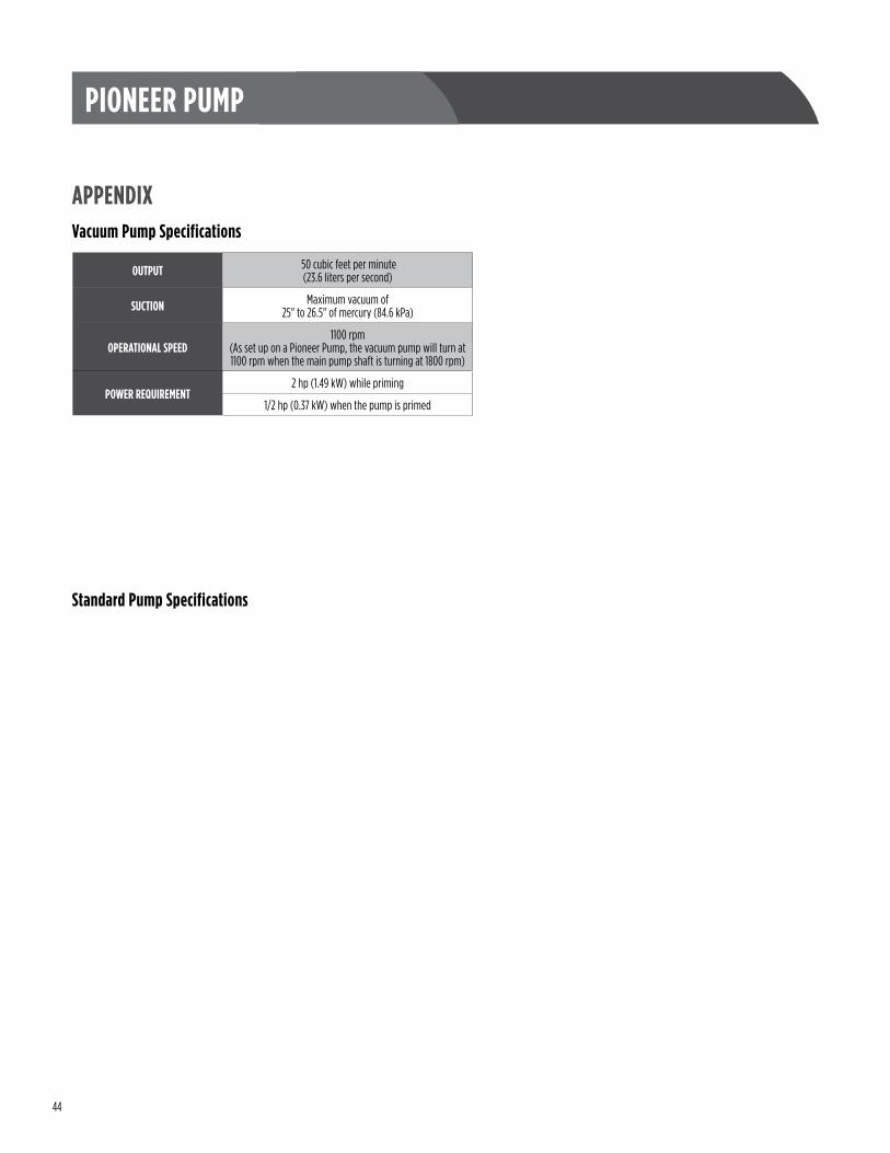
APPENDIXVacuum Pump Specifications
OUTPUT 50 cubic feet per minute (23 .6 liters per second)
SUCTION Maximum vacuum of 25" to 26 .5" of mercury (84 .6 kPa)
OPERATIONAL SPEED1100 rpm
(As set up on a Pioneer Pump, the vacuum pump will turn at 1100 rpm when the main pump shaft is turning at 1800 rpm)
POWER REQUIREMENT2 hp (1 .49 kW) while priming
1/2 hp (0 .37 kW) when the pump is primed
Standard Pump Specifications
45
PIONEER PUMP
APPENDIXParts Information
46
PIONEER PUMP
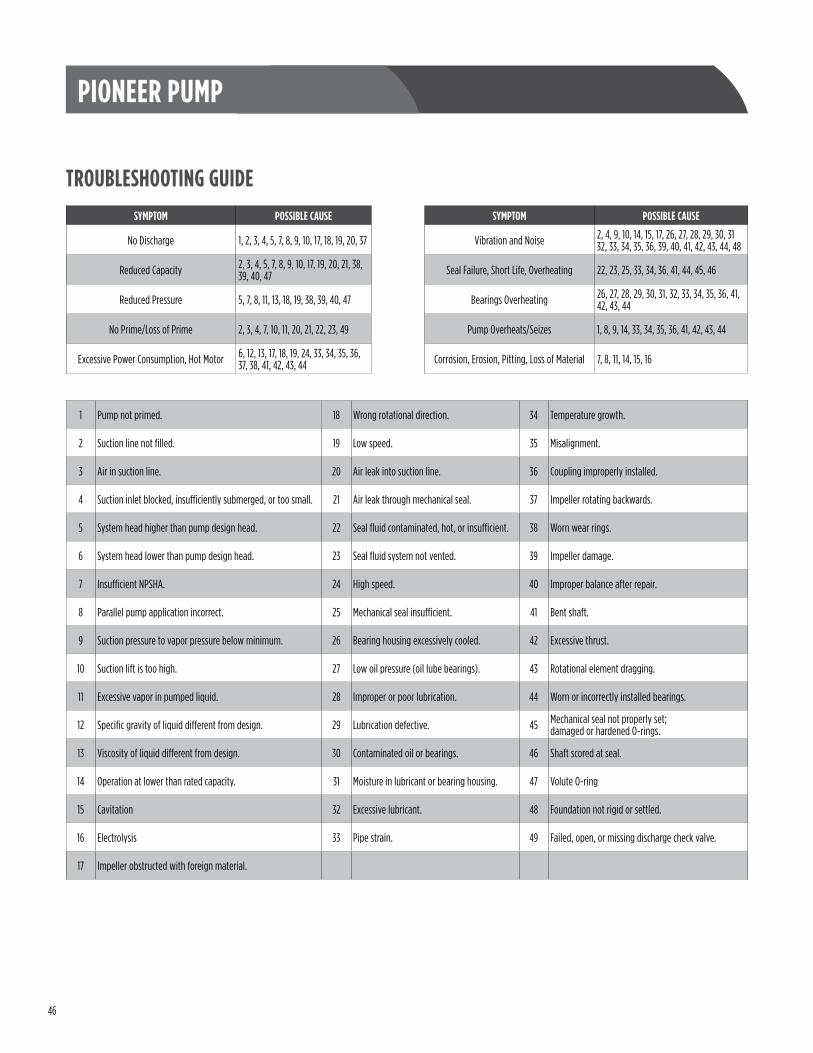
TROUBLESHOOTING GUIDE
1 Pump not primed . 18 Wrong rotational direction . 34 Temperature growth .
2 Suction line not filled . 19 Low speed . 35 Misalignment .
3 Air in suction line . 20 Air leak into suction line . 36 Coupling improperly installed .
4 Suction inlet blocked, insufficiently submerged, or too small . 21 Air leak through mechanical seal . 37 Impeller rotating backwards .
5 System head higher than pump design head . 22 Seal fluid contaminated, hot, or insufficient . 38 Worn wear rings .
6 System head lower than pump design head . 23 Seal fluid system not vented . 39 Impeller damage .
7 Insufficient NPSHA . 24 High speed . 40 Improper balance after repair .
8 Parallel pump application incorrect . 25 Mechanical seal insufficient . 41 Bent shaft .
9 Suction pressure to vapor pressure below minimum . 26 Bearing housing excessively cooled . 42 Excessive thrust .
10 Suction lift is too high . 27 Low oil pressure (oil lube bearings) . 43 Rotational element dragging .
11 Excessive vapor in pumped liquid . 28 Improper or poor lubrication . 44 Worn or incorrectly installed bearings .
12 Specific gravity of liquid different from design . 29 Lubrication defective . 45 Mechanical seal not properly set; damaged or hardened O-rings .
13 Viscosity of liquid different from design . 30 Contaminated oil or bearings . 46 Shaft scored at seal .
14 Operation at lower than rated capacity . 31 Moisture in lubricant or bearing housing . 47 Volute O-ring
15 Cavitation 32 Excessive lubricant . 48 Foundation not rigid or settled .
16 Electrolysis 33 Pipe strain . 49 Failed, open, or missing discharge check valve .
17 Impeller obstructed with foreign material .
SYMPTOM POSSIBLE CAUSE
No Discharge 1, 2, 3, 4, 5, 7, 8, 9, 10, 17, 18, 19, 20, 37
Reduced Capacity 2, 3, 4, 5, 7, 8, 9, 10, 17, 19, 20, 21, 38, 39, 40, 47
Reduced Pressure 5, 7, 8, 11, 13, 18, 19, 38, 39, 40, 47
No Prime/Loss of Prime 2, 3, 4, 7, 10, 11, 20, 21, 22, 23, 49
Excessive Power Consumption, Hot Motor 6, 12, 13, 17, 18, 19, 24, 33, 34, 35, 36, 37, 38, 41, 42, 43, 44
SYMPTOM POSSIBLE CAUSE
Vibration and Noise 2, 4, 9, 10, 14, 15, 17, 26, 27, 28, 29, 30, 31 32, 33, 34, 35, 36, 39, 40, 41, 42, 43, 44, 48
Seal Failure, Short Life, Overheating 22, 23, 25, 33, 34, 36, 41, 44, 45, 46
Bearings Overheating 26, 27, 28, 29, 30, 31, 32, 33, 34, 35, 36, 41, 42, 43, 44
Pump Overheats/Seizes 1, 8, 9, 14, 33, 34, 35, 36, 41, 42, 43, 44
Corrosion, Erosion, Pitting, Loss of Material 7, 8, 11, 14, 15, 16

47
PIONEER PUMP

FORM 8001 REV . 0-A 12-18 pioneerpump .com | 503 .266 .4115