Embed Size (px)
Citation preview
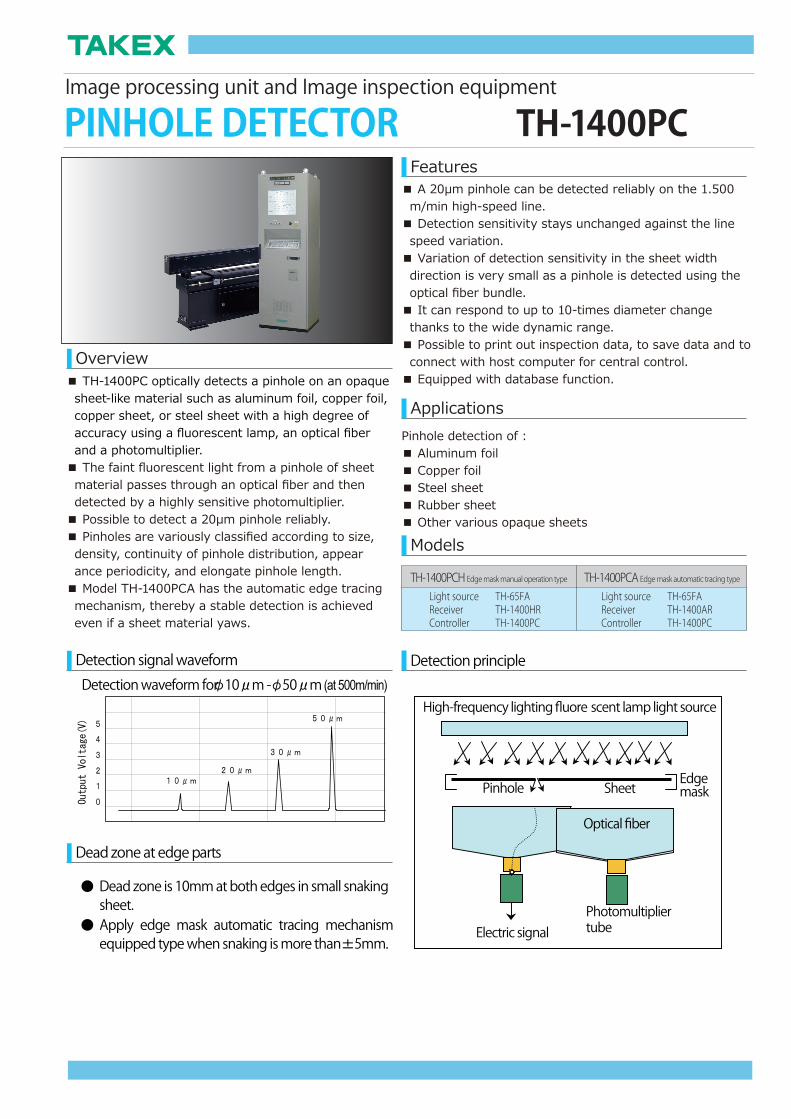
Image processing unit and Image inspection equipment
PINHOLE DETECTOR TH-1400PCFeatures
■ TH-1400PC optically detects a pinhole on an opaque sheet-like material such as aluminum foil, copper foil, copper sheet, or steel sheet with a high degree of accuracy using a fluorescent lamp, an optical fiber and a photomultiplier.■ The faint fluorescent light from a pinhole of sheet material passes through an optical fiber and then detected by a highly sensitive photomultiplier.■ Possible to detect a 20μm pinhole reliably. ■ Pinholes are variously classified according to size, density, continuity of pinhole distribution, appear ance periodicity, and elongate pinhole length.■ Model TH-1400PCA has the automatic edge tracing mechanism, thereby a stable detection is achieved even if a sheet material yaws.
Detection signal waveform
■ A 20μm pinhole can be detected reliably on the 1.500 m/min high-speed line.■ Detection sensitivity stays unchanged against the line speed variation.■ Variation of detection sensitivity in the sheet width direction is very small as a pinhole is detected using the optical fiber bundle.■ It can respond to up to 10-times diameter change thanks to the wide dynamic range.■ Possible to print out inspection data, to save data and to connect with host computer for central control. ■ Equipped with database function.
Pinhole detection of :■ Aluminum foil■ Copper foil■ Steel sheet■ Rubber sheet■ Other various opaque sheets
Overview
Dead zone at edge parts
Applications
Models
Detection principle
TH-1400PCH Edge mask manual operation type TH-1400PCA Edge mask automatic tracing typeTH-65FATH-1400HRTH-1400PC
Light source Receiver Controller
TH-65FATH-1400ARTH-1400PC
Light source Receiver Controller
Detection waveform for 10 m - 50 m (at 500m/min)
Dead zone is 10mm at both edges in small snaking sheet.Apply edge mask automatic tracing mechanism equipped type when snaking is more than 5mm.
High-frequency lighting fluore scent lamp light source
Sheet
Optical fiber
Pinhole
PhotomultipliertubeElectric signal
Edgemask
Configuration chart of device
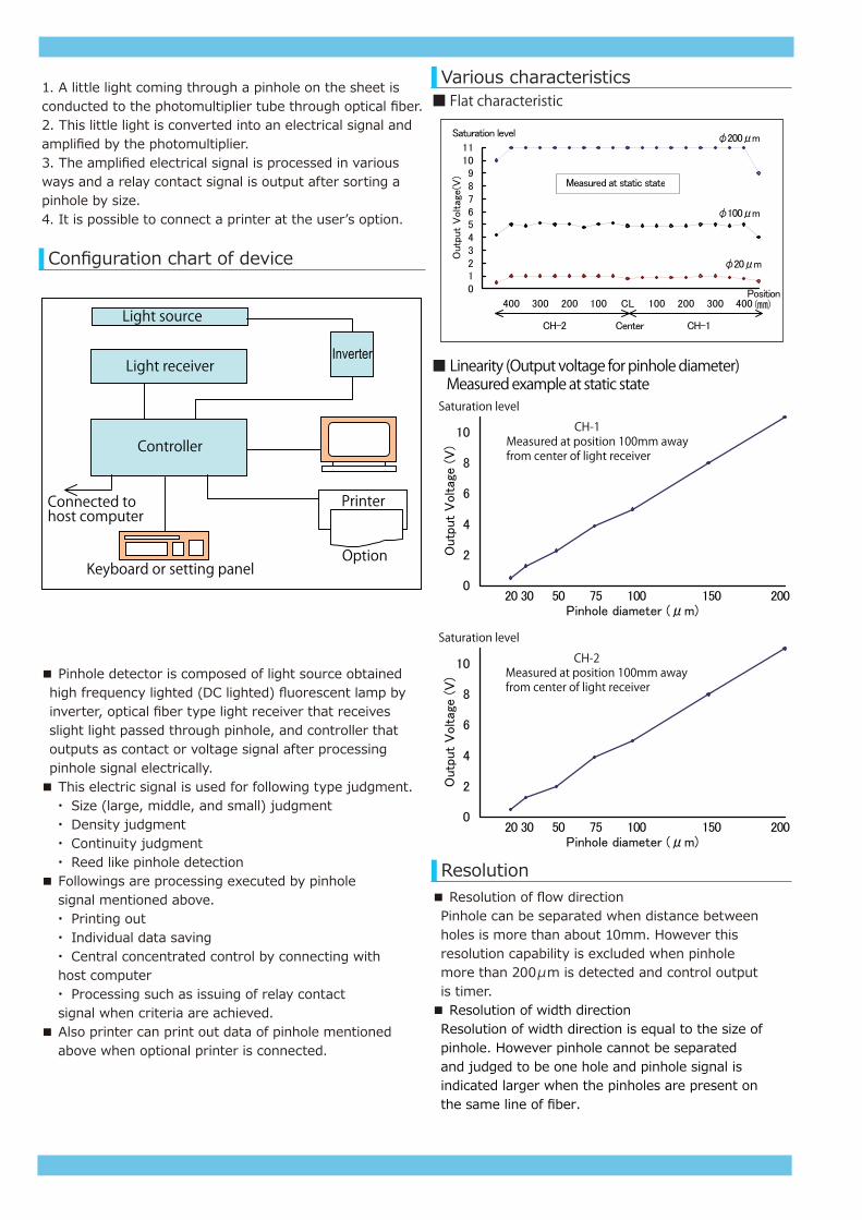
1. A little light coming through a pinhole on the sheet is conducted to the photomultiplier tube through optical fiber.2. This little light is converted into an electrical signal and amplified by the photomultiplier.3. The amplified electrical signal is processed in various ways and a relay contact signal is output after sorting a pinhole by size.4. It is possible to connect a printer at the userʼs option.
Light receiver
Printer
Controller
Light source
Option
Connected tohost computer
Keyboard or setting panel
Inverter
■ Pinhole detector is composed of light source obtained high frequency lighted (DC lighted) fluorescent lamp by inverter, optical fiber type light receiver that receives slight light passed through pinhole, and controller that outputs as contact or voltage signal after processing pinhole signal electrically.■ This electric signal is used for following type judgment. ・ Size (large, middle, and small) judgment ・ Density judgment ・ Continuity judgment ・ Reed like pinhole detection■ Followings are processing executed by pinhole signal mentioned above. ・ Printing out ・ Individual data saving ・ Central concentrated control by connecting with host computer ・ Processing such as issuing of relay contact signal when criteria are achieved.■ Also printer can print out data of pinhole mentioned above when optional printer is connected.
Various characteristics
Resolution
■ Flat characteristic
■ Linearity (Output voltage for pinhole diameter) Measured example at static state
Saturation level CH-2
Measured at position 100mm away from center of light receiver
Saturation level CH-1
Measured at position 100mm away from center of light receiver
■ Resolution of flow direction Pinhole can be separated when distance between holes is more than about 10mm. However this resolution capability is excluded when pinhole more than 200μm is detected and control output is timer.■ Resolution of width direction Resolution of width direction is equal to the size of pinhole. However pinhole cannot be separated and judged to be one hole and pinhole signal is indicated larger when the pinholes are present on the same line of fiber.
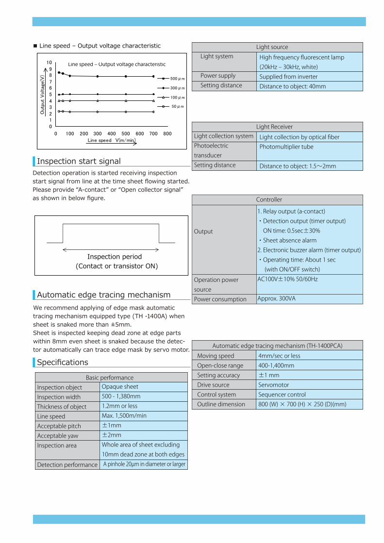
■ Line speed – Output voltage characteristic
Line speed ‒ Output voltage characteristic
Inspection start signal
Automatic edge tracing mechanism
Specifications
Detection operation is started receiving inspection start signal from line at the time sheet flowing started.Please provide “A-contact” or “Open collector signal” as shown in below figure.
Inspection period (Contact or transistor ON)
We recommend applying of edge mask automatictracing mechanism equipped type (TH -1400A) whensheet is snaked more than ±5mm.Sheet is inspected keeping dead zone at edge partswithin 8mm even sheet is snaked because the detec-tor automatically can trace edge mask by servo motor.
High frequency fluorescent lamp
(20kHz ‒ 30kHz, white)
Supplied from inverter
Distance to object: 40mm
Inspection object
Inspection width
Thickness of object
Line speed
Acceptable pitch
Acceptable yaw
Inspection area
Detection performance
Opaque sheet
500 - 1,380mm
1.2mm or less
Max. 1,500m/min
±1mm
±2mm
Whole area of sheet excluding
10mm dead zone at both edges
A pinhole 20µm in diameter or larger
Basic performance
Light system
Power supply
Setting distance
Light source
Light collection by optical fiber
Photomultiplier tube
Distance to object: 1.5~2mm
Light collection system
Photoelectric
transducer
Setting distance
Light Receiver
Output
Operation power
source
Power consumption
Controller
1. Relay output (a-contact)
・Detection output (timer output)
ON time: 0.5sec±30%
・Sheet absence alarm
2. Electronic buzzer alarm (timer output)
・Operating time: About 1 sec
(with ON/OFF switch)
AC100V±10% 50/60Hz
Approx. 300VA
Moving speed
Open-close range
Setting accuracy
Drive source
Control system
Outline dimension
Automatic edge tracing mechanism (TH-1400PCA)
4mm/sec or less
400-1,400mm
±1 mm
Servomotor
Sequencer control
800 (W) × 700 (H) × 250 (D)(mm)
TAKENAKA SYSTEM CO., LTD.
Headoffice:
86-66, Nomizo-cho, Ohtsuka, Yamashina-ku,Kyoto City 607-8135, JAPANTEL: +81-75-593-9300 FAX: +81-75-593-9790 E-mail: sales @takex-system.co.jp
TAKENAKA SYSTEM URL: http://www..takex-system.co.jpTAKENAKA SENSOR GROUP URL: http://www.takex.co.jp
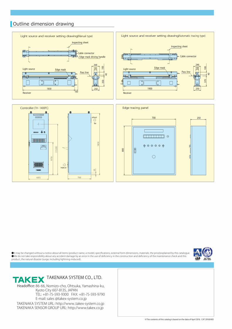
Outline dimension drawing
Inspecting sheet
Edge mask driving handleCable connector
Edge maskLight sourcePass line
Receiver
268100 10
040
350
250
Inspecting sheet
Cable connector
Light source
Receiver
Edge maskPass line
1830100
1900 250
100246
100
40370
800
700 250
Light source and receiver setting drawing(Manual type) Light source and receiver setting drawing(Automatic tracing type)
Controller (TH -1400PC) Edge tracing panel
TP-0672C ピ ン ホ ー ル 検 出 装 置
700
50
fan
1850
605
Intake air
exhaust
(152
0)
970
●It may be changed without a notice about all items (product name, a model, specifications, external form dimensions, materials, the price)explained by this catalogue.●We do not take responsibility about any accident damage by an error in the use of deficiency in the construction and deficiency of the maintenance check and this product, the natural disaster (surge, including lightning-induced).
※The contents of this catalog is based on the data of April 2016. CAT 20160405