Embed Size (px)
Citation preview

Pin Fin Lab Report Example
Names
ME331 Lab
04/12/2017
1. Abstract
The purposes of this experiment are to determine pin fin effectiveness and convective heat transfer coefficients for free and forced convection over pin fins of differing length and material. The results from pin fins made of copper, aluminum, and stainless steel showed differing temperature distributions, heat transfer coefficients, and fin effectiveness values. One of the pin fins, made of stainless steel, can be treated as an “infinitely long fin.”
2. Introduction / Theory
Empirical correlations from heat transfer allow one to estimate free and forced convective heat transfer coefficients. Because empirical correlations typically cover a wide range of fluids and flow conditions, an estimated convection coefficient can deviate from the real value by 20% or more. More accurate measures of convective heat transfer coefficients can be determined experimentally by obtaining temperature differences and/or heat transfer rates using a testing prototype. In this experiment, temperature distributions for three different pin fins are measured under natural and forced convection boundary conditions. The three cylindrical-rod pin fins used in these experiments are made of copper, stainless steel, and aluminum. The rate of heat transfer into each pin fin is determined by the electrical power of the heater at the base of the fin and by the conduction rate through the base of the fin. The primary purpose of this experiment is to compare heat transfer coefficients obtained experimentally with estimated values from (text book) empirical correlations. The secondary purpose is to compare values of pin fin effectiveness for different fin lengths and materials.
3. Procedure
The apparatus consists of three different fins, each with a heater at the base of the fin surrounded by insulation to reduce heat loss. Five to seven thermocouples are placed along the longitudinal direction. Temperatures are measured, displayed and recorded with DAQ devices. Two Keithley meters measure the voltage and current drawn by the heater in order to measure the electrical power. A switch box selects the fin being monitored by the Keithley meters.
4. Results
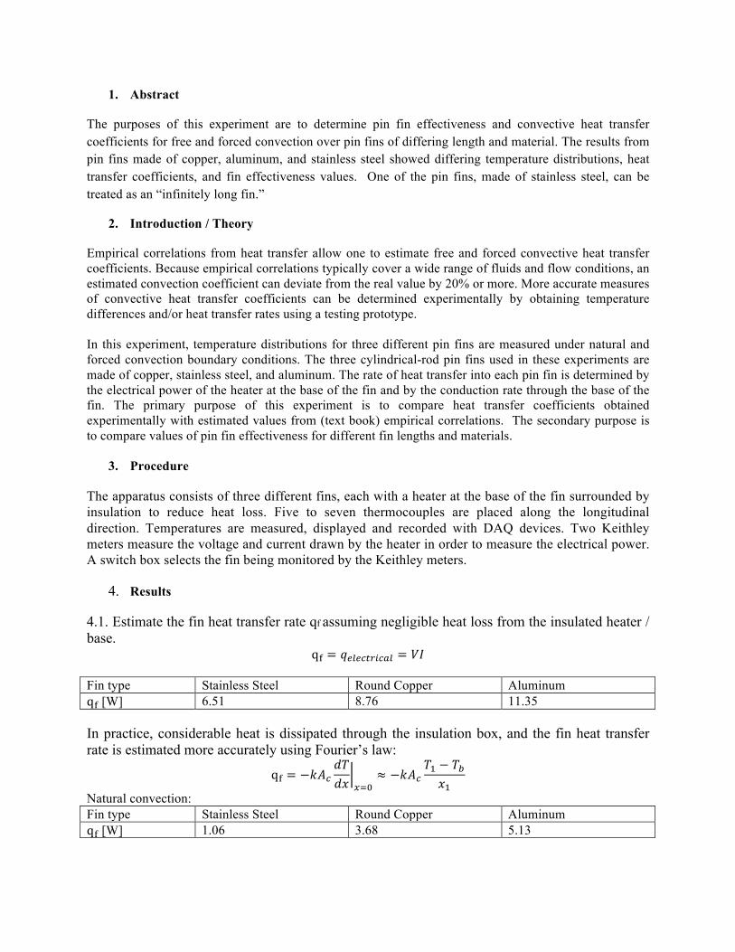
4.1. Estimate the fin heat transfer rate qf assuming negligible heat loss from the insulated heater / base.
q! = 𝑞!"!#$%&#'" = 𝑉𝐼 Fin type Stainless Steel Round Copper Aluminum q! [W] 6.51 8.76 11.35 In practice, considerable heat is dissipated through the insulation box, and the fin heat transfer rate is estimated more accurately using Fourier’s law:
q! = −𝑘𝐴!𝑑𝑇𝑑𝑥 !!!
≈ −𝑘𝐴!𝑇! − 𝑇!𝑥!
Natural convection: Fin type Stainless Steel Round Copper Aluminum q! [W] 1.06 3.68 5.13
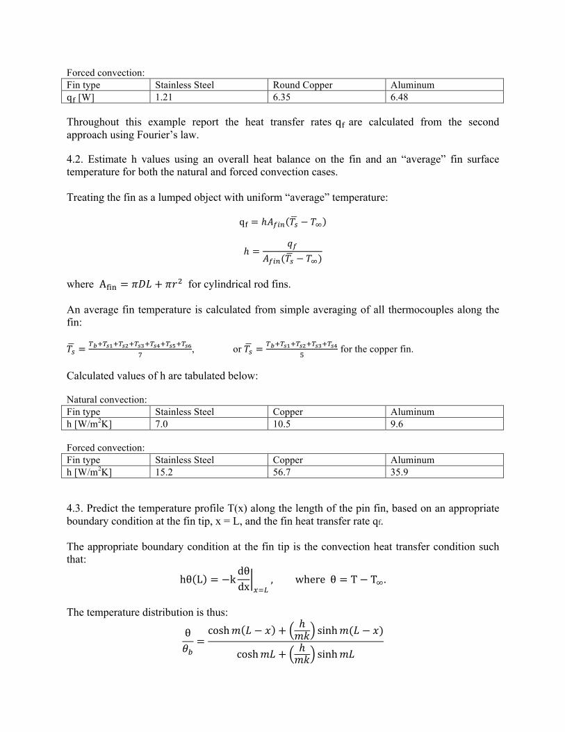
Forced convection: Fin type Stainless Steel Round Copper Aluminum q! [W] 1.21 6.35 6.48 Throughout this example report the heat transfer rates q! are calculated from the second approach using Fourier’s law. 4.2. Estimate h values using an overall heat balance on the fin and an “average” fin surface temperature for both the natural and forced convection cases. Treating the fin as a lumped object with uniform “average” temperature:
q! = ℎ𝐴!"# 𝑇! − 𝑇!
ℎ =𝑞!
𝐴!"#(𝑇! − 𝑇!)
where A!"# = 𝜋𝐷𝐿 + 𝜋𝑟! for cylindrical rod fins. An average fin temperature is calculated from simple averaging of all thermocouples along the fin: 𝑇! =
!!!!!!!!!!!!!!!!!!!!!!!!!!!
, or 𝑇! =!!!!!!!!!!!!!!!!!!
! for the copper fin.
Calculated values of h are tabulated below: Natural convection: Fin type Stainless Steel Copper Aluminum h [W/m2K] 7.0 10.5 9.6 Forced convection: Fin type Stainless Steel Copper Aluminum h [W/m2K] 15.2 56.7 35.9 4.3. Predict the temperature profile T(x) along the length of the pin fin, based on an appropriate boundary condition at the fin tip, x = L, and the fin heat transfer rate qf. The appropriate boundary condition at the fin tip is the convection heat transfer condition such that:
hθ L = −kdθdx !!!
, where θ = T− T!.
The temperature distribution is thus:
θ𝜃!=cosh𝑚 𝐿 − 𝑥 + ℎ
𝑚𝑘 sinh𝑚(𝐿 − 𝑥)
cosh𝑚𝐿 + ℎ𝑚𝑘 sinh𝑚𝐿
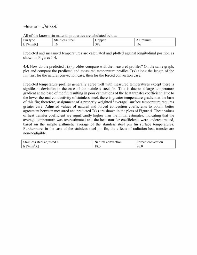
where m = ℎ𝑃/𝑘𝐴! All of the known fin material properties are tabulated below: Fin type Stainless Steel Copper Aluminum k [W/mK] 16 388 167 Predicted and measured temperatures are calculated and plotted against longitudinal position as shown in Figures 1-4. 4.4. How do the predicted T(x) profiles compare with the measured profiles? On the same graph, plot and compare the predicted and measured temperature profiles T(x) along the length of the fin, first for the natural convection case, then for the forced convection case. Predicted temperature profiles generally agree well with measured temperatures except there is significant deviation in the case of the stainless steel fin. This is due to a large temperature gradient at the base of the fin resulting in poor estimations of the heat transfer coefficient. Due to the lower thermal conductivity of stainless steel, there is greater temperature gradient at the base of this fin; therefore, assignment of a properly weighted "average" surface temperature requires greater care. Adjusted values of natural and forced convection coefficients to obtain better agreement between measured and predicted T(x) are shown in the plots of Figure 4. These values of heat transfer coefficient are significantly higher than the initial estimates, indicating that the average temperature was overestimated and the heat transfer coefficients were underestimated, based on the simple arithmetic average of the stainless steel pin fin surface temperatures. Furthermore, in the case of the stainless steel pin fin, the effects of radiation heat transfer are non-negligible. Stainless steel adjusted h Natural convection Forced convection h [W/m2K] 18.3 76.0
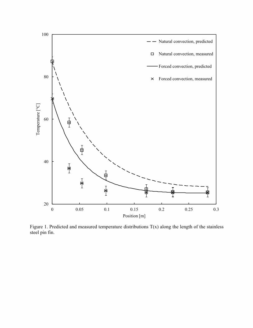
Figure 1. Predicted and measured temperature distributions T(x) along the length of the stainless steel pin fin.
20
40
60
80
100
0 0.05 0.1 0.15 0.2 0.25 0.3
Tem
pera
ture
[°C
]
Position [m]
Natural convection, predicted
Natural convection, measured
Forced convection, predicted
Forced convection, measured
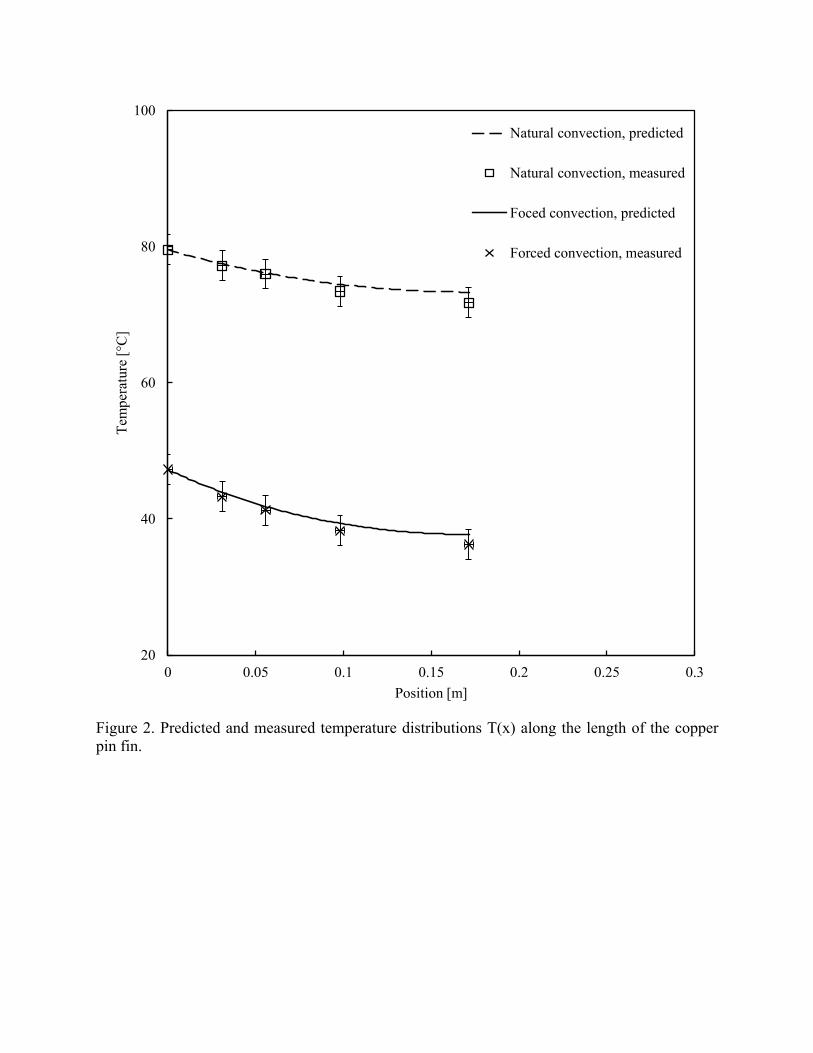
Figure 2. Predicted and measured temperature distributions T(x) along the length of the copper pin fin.
20
40
60
80
100
0 0.05 0.1 0.15 0.2 0.25 0.3
Tem
pera
ture
[°C
]
Position [m]
Natural convection, predicted
Natural convection, measured
Foced convection, predicted
Forced convection, measured
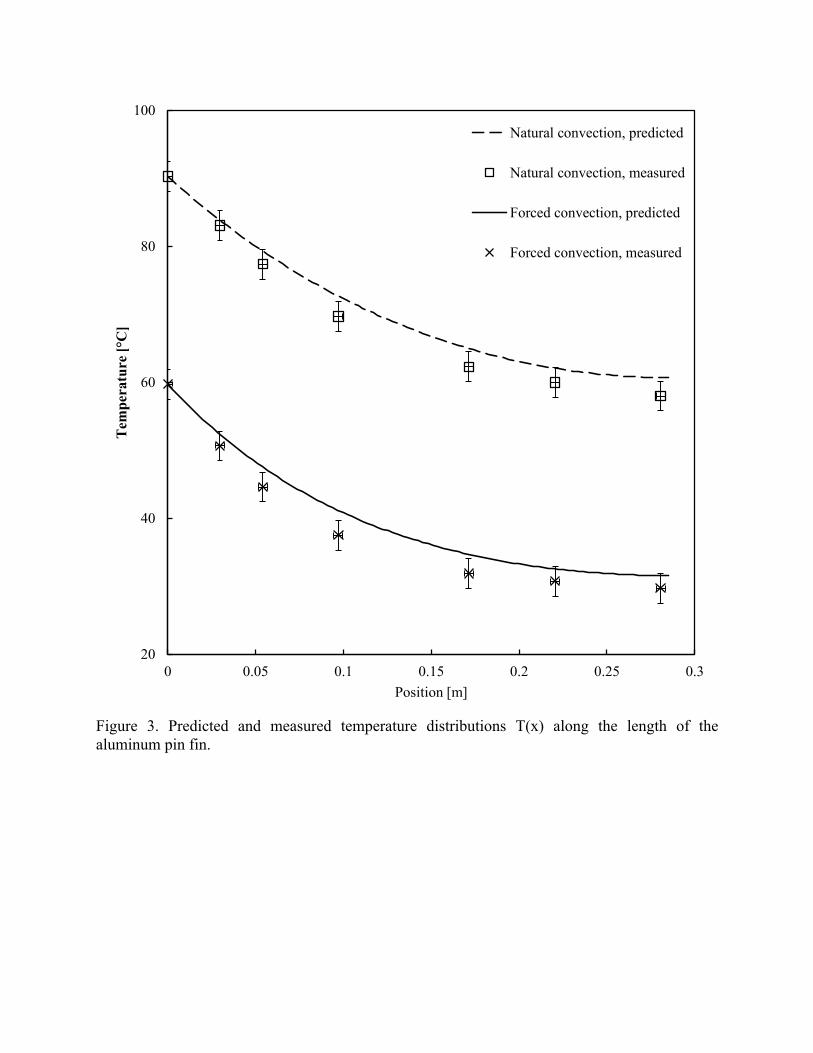
Figure 3. Predicted and measured temperature distributions T(x) along the length of the aluminum pin fin.
20
40
60
80
100
0 0.05 0.1 0.15 0.2 0.25 0.3
Tem
pera
ture
[°C
]
Position [m]
Natural convection, predicted
Natural convection, measured
Forced convection, predicted
Forced convection, measured
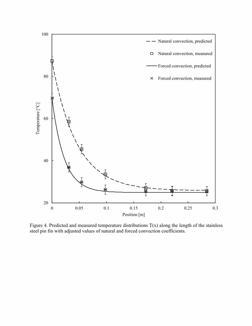
Figure 4. Predicted and measured temperature distributions T(x) along the length of the stainless steel pin fin with adjusted values of natural and forced convection coefficients.
20
40
60
80
100
0 0.05 0.1 0.15 0.2 0.25 0.3
Tem
pera
ture
[°C
]
Position [m]
Natural convection, predicted
Natural convection, measured
Forced convection, predicted
Forced convection, measured
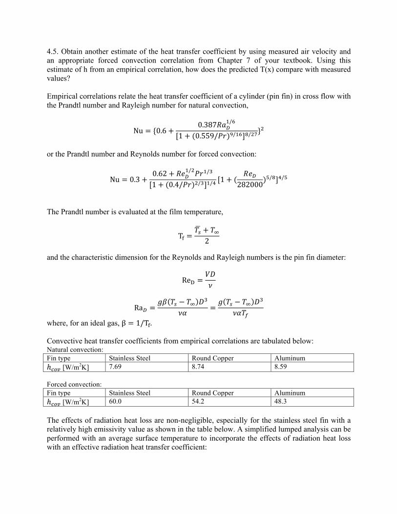
4.5. Obtain another estimate of the heat transfer coefficient by using measured air velocity and an appropriate forced convection correlation from Chapter 7 of your textbook. Using this estimate of h from an empirical correlation, how does the predicted T(x) compare with measured values? Empirical correlations relate the heat transfer coefficient of a cylinder (pin fin) in cross flow with the Prandtl number and Rayleigh number for natural convection,
Nu = {0.6+0.387𝑅𝑎!
!/!
[1+ (0.559/𝑃𝑟)!/!"]!/!"}!
or the Prandtl number and Reynolds number for forced convection:
Nu = 0.3+0.62+ 𝑅𝑒!
!/!𝑃𝑟!/!
[1+ (0.4/𝑃𝑟)!/!]!/! [1+ (𝑅𝑒!
282000)!/!]!/!
The Prandtl number is evaluated at the film temperature,
T! =𝑇! + 𝑇!
2 and the characteristic dimension for the Reynolds and Rayleigh numbers is the pin fin diameter:
Re! =𝑉𝐷𝜈
Ra! =𝑔𝛽 𝑇! − 𝑇! 𝐷!
𝜈𝛼 =𝑔 𝑇! − 𝑇! 𝐷!
𝜈𝛼𝑇!
where, for an ideal gas, β = 1/T!. Convective heat transfer coefficients from empirical correlations are tabulated below: Natural convection: Fin type Stainless Steel Round Copper Aluminum ℎ!"# [W/m2K] 7.69 8.74 8.59 Forced convection: Fin type Stainless Steel Round Copper Aluminum ℎ!"# [W/m2K] 60.0 54.2 48.3 The effects of radiation heat loss are non-negligible, especially for the stainless steel fin with a relatively high emissivity value as shown in the table below. A simplified lumped analysis can be performed with an average surface temperature to incorporate the effects of radiation heat loss with an effective radiation heat transfer coefficient:
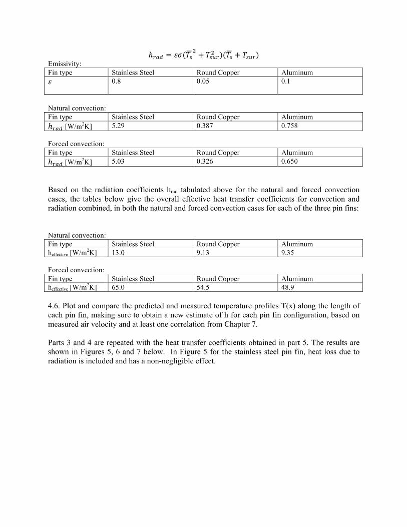
ℎ!"# = 𝜀𝜎(𝑇!! + 𝑇!"#! )(𝑇! + 𝑇!"#)
Emissivity: Fin type Stainless Steel Round Copper Aluminum 𝜀 0.8 0.05 0.1
Natural convection: Fin type Stainless Steel Round Copper Aluminum ℎ!"# [W/m2K] 5.29 0.387 0.758 Forced convection: Fin type Stainless Steel Round Copper Aluminum ℎ!"# [W/m2K] 5.03 0.326 0.650 Based on the radiation coefficients hrad tabulated above for the natural and forced convection cases, the tables below give the overall effective heat transfer coefficients for convection and radiation combined, in both the natural and forced convection cases for each of the three pin fins: Natural convection: Fin type Stainless Steel Round Copper Aluminum heffective [W/m2K] 13.0 9.13 9.35 Forced convection: Fin type Stainless Steel Round Copper Aluminum heffective [W/m2K] 65.0 54.5 48.9 4.6. Plot and compare the predicted and measured temperature profiles T(x) along the length of each pin fin, making sure to obtain a new estimate of h for each pin fin configuration, based on measured air velocity and at least one correlation from Chapter 7. Parts 3 and 4 are repeated with the heat transfer coefficients obtained in part 5. The results are shown in Figures 5, 6 and 7 below. In Figure 5 for the stainless steel pin fin, heat loss due to radiation is included and has a non-negligible effect.
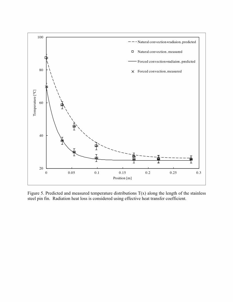
Figure 5. Predicted and measured temperature distributions T(x) along the length of the stainless steel pin fin. Radiation heat loss is considered using effective heat transfer coefficient.
20
40
60
80
100
0 0.05 0.1 0.15 0.2 0.25 0.3
Tem
pera
ture
[°C]
Position [m]
Natural convection+radiaion, predicted
Natural convection, measured
Forced convection+radiaion, predicted
Forced convection, measured
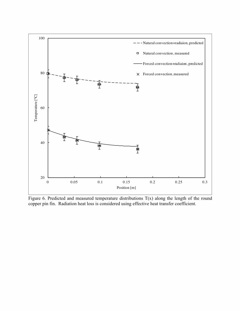
Figure 6. Predicted and measured temperature distributions T(x) along the length of the round copper pin fin. Radiation heat loss is considered using effective heat transfer coefficient.
20
40
60
80
100
0 0.05 0.1 0.15 0.2 0.25 0.3
Tem
pera
ture
[°C]
Position [m]
Natural convection+radiaion, predicted
Natural convection, measured
Forced convection+radiaion, predicted
Forced convection, measured
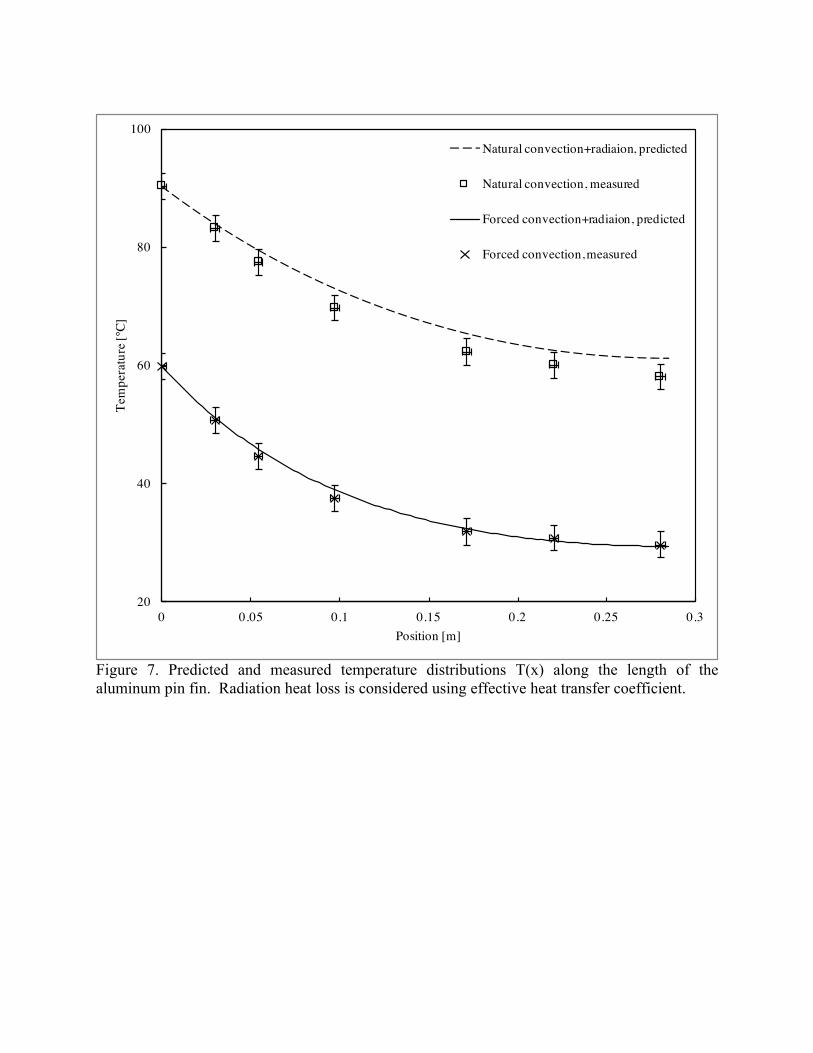
Figure 7. Predicted and measured temperature distributions T(x) along the length of the aluminum pin fin. Radiation heat loss is considered using effective heat transfer coefficient.
20
40
60
80
100
0 0.05 0.1 0.15 0.2 0.25 0.3
Tem
pera
ture
[°C]
Position [m]
Natural convection+radiaion, predicted
Natural convection, measured
Forced convection+radiaion, predicted
Forced convection, measured
4.7. Calculate the fin effectiveness for all three pin fins, both natural and forced convection cases. Fin effectiveness is the ratio of the fin heat transfer rate to the heat transfer rate that would exist without the fin:
ε! =𝑞!
ℎ𝐴!𝜃!
Natural convection: Fin type Stainless Steel Round Copper Aluminum
ε! 34 50 64 Forced convection: Fin type Stainless Steel Round Copper Aluminum
ε! 25 39 41
5. Discussion (25%)
5.1. The accuracy of your estimates of convection coefficients h. What are potential sources of error? The accuracy of the convection coefficients calculated from an average fin surface temperature relies on the accuracy of measured q!, 𝐴! , and average surface temperature. The heat loss through the insulation contributes to the error of q! ; 𝐴! is as accurate as the geometry measurement of the fin; surface temperature error comes from thermocouple error and averaging error occurs from the discrete positions of the thermocouples which yields an approximate average rather than a true surface temperature average. The assumption of uniform temperature also results in less accurate values of h. The accuracy of the convection coefficients calculated from empirical relations relies on the measured air velocity for forced convection and temperature difference from thermocouples. Again, the assumption of uniform properties (temperature, air velocity, air properties) affects the accuracy of h. There is also uncertainty from the empirical relation itself. 5.2. Discuss the uncertainty of forced convection air velocities. Estimate velocity measurement error. The air velocity profile as a function of position along the pin fin is plotted in appendix C of the lab manual. The standard deviation of the velocity is approximately 20% of the mean value. While the correlation is not linear against air velocity, similar uncertainty can be expected from the results of part 5. 5.3. Estimate the heat dissipated from the electric heater through the backing insulation. How does this compare with the fin heat transfer rate?
The heat transfer rate q! can be estimated using the theory of heat transfer from extended surfaces:
q! = 𝑀sinh𝑚𝐿 + ℎ
𝑚𝑘 cosh𝑚𝐿
cosh𝑚𝐿 + ℎ𝑚𝑘 sinh𝑚𝐿
where M = ℎ𝑃𝑘𝐴!θ!. Subtracting q! from the measured heater power, we can estimate the heat dissipation from the insulation. Natural convection: Fin type Stainless Steel Round Copper Aluminum q!"# (W) 5.0 5.1 6.4 Forced convection: Fin type Stainless Steel Round Copper Aluminum q!"# (W) 4.2 2.7 5.4 The dissipation rate varies in the same trend of fin base temperature, which is consistent with expectation. Similar analysis can be drawn from q! = −𝑘𝐴!
!"!" !!!
≈ −𝑘𝐴!!!!!!!!
:
Natural convection: Fin type Stainless Steel Round Copper Aluminum q!"# (W) 5.4 5.1 6.2 Forced convection: Fin type Stainless Steel Round Copper Aluminum q!"# (W) 5.3 2.4 4.9 5.4. What is the effect of neglecting radiation? Are the errors greater or lesser for natural convection compared to forced convection cases? Previous analyses assumed convection as the only heat transfer mode; however, radiation heat transfer should also be included, particularly for the stainless steel pin fin. The heat transfer coefficient calculated should be considered as a “combined” heat transfer coefficient including both convection and radiation. The fact that the h values calculated from empirical correlations are less than experimental h values (using method of average surface temperature) is consistent with the argument that radiation heat loss must be included. The “effective” radiation heat transfer coefficient can be described as: h!"# = 𝜀𝜎(𝑇!! + 𝑇!"#! )(𝑇! + 𝑇!"#) for a uniform and steady surface temperature. The average fin temperature under forced convection is less than that under natural convection, due to greater convection coefficient (and therefore greater “combined” heat transfer coefficient). Therefore the
error of neglecting radiation is less when the surface temperature is lower, hence under forced convection. 5.5. Compare predicted and measured temperature profiles T(x) along the length of each pin fin. Estimate an error range for measured location of the thermocouples and include (horizontal) error bars on all plots of T(x) versus x. What is the typical accuracy of type K (un-calibrated) thermocouples? Include vertical error bars to illustrate uncertainty in the temperature measurements for all plots of T(x) versus x. Error range of measured locations of the thermocouples depends on the spot size of the thermocouple fixture and the accuracy associated with measuring from a specific fin base location. The measurement error in thermocouple location is estimated at 0.1”. Type K thermocouples have a standard error of 2.2°C according to the OMEGA website [1]. These uncertainty errors are reflected in Figures 1-7. 5.6. Could any of the fins be modeled as infinite? If so, explain. If not, what fin length would be needed for an infinite fin model to be valid? A fin can be considered infinite when the tip temperature is very close to ambient temperature, which suggests that additional fin length will not increase the rate of heat transfer. Typically, for mL > 2.65, the infinite fin criterion is considered satisfied. Of the four fins, the stainless steel fin can be treated as infinite as the value of mL is 9.6 and 13 for natural and forced convection respectively. 5.7. Compare the calculated values of fin effectiveness for natural and forced convection and for each of the four different pin fins. Compare and discuss each of the fin effectiveness values. The fin effectiveness describes how much heat is transferred compared to the scenario where there is no fin. The fin effectiveness values for natural convection are greater than those for forced convection, indicating that the fins are more effective when the heat transfer coefficient is low and surface temperature is high. The aluminum fin is slightly more effective than the copper fin (due to the higher emissivity of aluminum compared to copper), with the stainless steel fin being the least effective due to its low thermal conductivity (although its emissivity is relatively high). Stainless steel suffers from low thermal conductivity, and it therefore transfers less heat to the extended surface compared to other more conductive fin materials. Geometry differences might also account for some differences in fin effectiveness of the copper and aluminum fins.
6. Conclusion
In this experiment, the temperature distributions of three different pin fins were measured under natural and forced convection conditions. The convective heat transfer coefficients were calculated by average temperature method and empirical correlations. Radiation heat transfer is not negligible for the stainless steel pin fin. Furthermore, the stainless steel pin fin can be considered “infinitely long”, and it is the least effective of all three fins. Reference [1] Thermocouple. (2017, April 14). Retrieved from http://www.omega.com/prodinfo/thermocouples.html.