Embed Size (px)
Citation preview
TRT 800/HMode A, A-C, S
ATC Transponder
����Pilot’s
Operation Manual
Doc. No.: 03.210.010.11
Revision 2.0
28. June 2005
FILSERElectronic GmbH
Gewerbestr. 2D-86875 Waal
© Copyright 2005
FILSER Electronic GmbH or its subsidiaries
All Rights Reserved
MODE
FID
IDENT
ONOFF
X...
.X.. ..X.
...X
R
ACSFL 100
S
Filser Electronic GmbHOperation Manual Rev.2.0 28.06.2005
2 of 14
Record of Revisions
Record of Revisions
RETAIN THIS RECORD IN THE FRONT OF THEMANUAL. ON RECEIPT OFREVISIONS, INSERT REVISED PAGES IN THEMANUAL, AND ENTER DATE INSERTED ANDINITIALS.
REV /EDNo.
RevisionDate
InsertionDate / By
SBNumberIncluded
REV /ED No.
RevisionDate
InsertionDate /By
SBNumberED No.
2.0 28.06.05 De Witt None
Table of Contents
OPERATION MANUAL .......................................................................................................................... 3
1. GENERAL....................................................................................................................................... 3
2. FRONT PANEL OPERATION ........................................................................................................ 4
3. SYSTEM OPERATION................................................................................................................... 7
4. ERROR REPORTING / FAULT CODES...................................................................................... 10
5. COMMON AND EMERGENCY ID CODES.................................................................................. 12
Approval TRT800 ................................................................................................................................. 13
Approval TRT800H............................................................................................................................... 14
Filser Electronic GmbHOperation Manual Rev.2.0 28.06.2005
3 of 14
OPERATION MANUAL
1. GENERAL
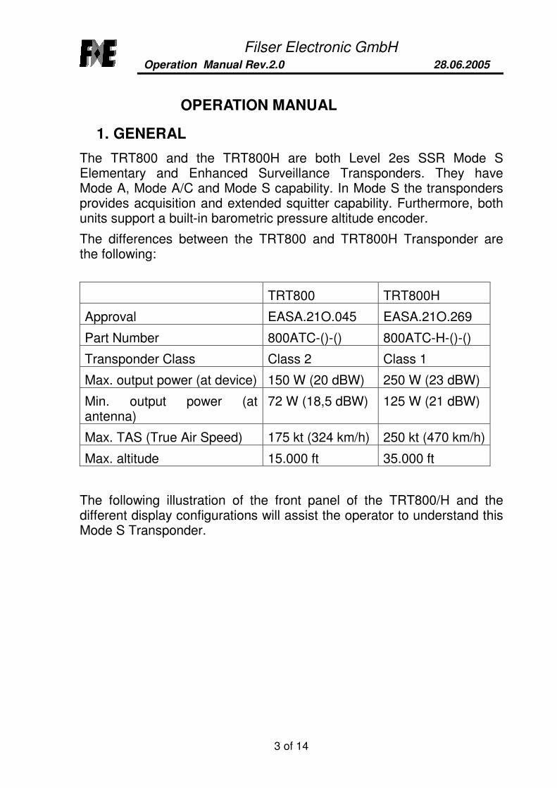
The TRT800 and the TRT800H are both Level 2es SSR Mode SElementary and Enhanced Surveillance Transponders. They haveMode A, Mode A/C and Mode S capability. In Mode S the transpondersprovides acquisition and extended squitter capability. Furthermore, bothunits support a built-in barometric pressure altitude encoder.
The differences between the TRT800 and TRT800H Transponder arethe following:
TRT800 TRT800H
Approval EASA.21O.045 EASA.21O.269
Part Number 800ATC-()-() 800ATC-H-()-()
Transponder Class Class 2 Class 1
Max. output power (at device) 150 W (20 dBW) 250 W (23 dBW)
Min. output power (atantenna)
72 W (18,5 dBW) 125 W (21 dBW)
Max. TAS (True Air Speed) 175 kt (324 km/h) 250 kt (470 km/h)
Max. altitude 15.000 ft 35.000 ft
The following illustration of the front panel of the TRT800/H and thedifferent display configurations will assist the operator to understand thisMode S Transponder.

Filser Electronic GmbHOperation Manual Rev.2.0 28.06.2005
4 of 14
2. FRONT PANEL OPERATION
The input elements consist of four rotating knobs and five push buttons.
MODE
FID
IDENT
ONOFF
X...
.X.. ..X.
...X
R
ACSFL 100
S
Active Code
Standby Code
Test Monitor Battery flag
Reply flag
Squitter flag(blinking)
Ident-Display
Mode indicator:STBYA-SACS
Flight Level
Rotating knobfor 1000
Rotating knobfor 100
Rotating knobfor 10
Rotating knobfor 1
Display or setFlight ID(FID)On / Off
Mode SelectSTBY, A-S, ACS
Exchange squawk codestandby to active
Set IDENT
FIn-Flight flag
Filser Electronic GmbHOperation Manual Rev.2.0 28.06.2005
5 of 14
Rotating knobs
Four rotating knobs are used to select the IDENT CODE.The assignments X… , .X.. , ..X. , …X indicate the position of thecode number set by each knob.
Push buttons
ON OFF
The unit can be turned on by pressing the ON OFF button for lessthen 1 second.The unit can be turned off by pressing the ON OFF button for morethen 2 seconds.
MODE
The following modes can be selected in sequence by pressing theMODE button:
• STBY Standby Mode used for aircraft on ground withreduced squitter rate, only Mode S withaltitude reporting all ZERO only
• A-S Mode A active with Mode C frames only andMode S with altitude reporting all ZERO only
• ACS Mode A ,C and S full active
����
To activate the inserted SQUAWK CODE from the lower standbyline to the upper active position the button with the up/down arrows
���� shall be pressed.
IDENT
The IDENT push button causes the special position identificationpulse (SPI) to be transmitted for a period of 18 seconds.
FID
In the STBY Mode, the Aircraft Identification (Flight Identification)and Aircraft Address can be checked by pressing the push buttonFID. The Flight Identification is displayed on the right side of thelower line. By pressing the button FID for more than 3 seconds theinput mode can be set or the Flight Identification can be changed.
Filser Electronic GmbHOperation Manual Rev.2.0 28.06.2005
6 of 14
Flags
Squitter Flag
When the extended squitter is active the letter S is displayed on theleft top side of the display. As the squitter is a periodic signal, thedisplayed S is blinking.
Reply Flag
In case of the transponder replying to interrogations the letter R isdisplayed on the left top side of the display.
In-Flight Flag
When there is an undercarriage switch installed, the display cantoggle between the letters F whether the aircraft is in flightcondition or the letter G whether the aircraft is in “on-ground”condition. The flag is displayed on the right bottom side of thedisplay.
Battery Flag
If the power supply to the transponder drops below 10 Volts, theflag BAT appears and starts flashing.
Filser Electronic GmbHOperation Manual Rev.2.0 28.06.2005
7 of 14
3. SYSTEM OPERATION
The Transponder should be turned off before starting aircraft engines.
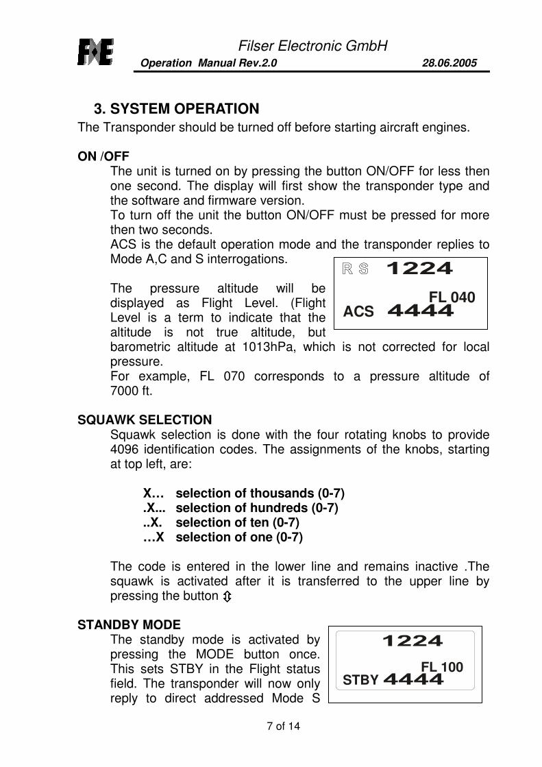
ON /OFFThe unit is turned on by pressing the button ON/OFF for less thenone second. The display will first show the transponder type andthe software and firmware version.To turn off the unit the button ON/OFF must be pressed for morethen two seconds.ACS is the default operation mode and the transponder replies toMode A,C and S interrogations.
The pressure altitude will bedisplayed as Flight Level. (FlightLevel is a term to indicate that thealtitude is not true altitude, butbarometric altitude at 1013hPa, which is not corrected for localpressure.For example, FL 070 corresponds to a pressure altitude of7000 ft.
SQUAWK SELECTIONSquawk selection is done with the four rotating knobs to provide4096 identification codes. The assignments of the knobs, startingat top left, are:
X… selection of thousands (0-7).X... selection of hundreds (0-7)..X. selection of ten (0-7)…X selection of one (0-7)
The code is entered in the lower line and remains inactive .Thesquawk is activated after it is transferred to the upper line bypressing the button ����
STANDBY MODEThe standby mode is activated bypressing the MODE button once.This sets STBY in the Flight statusfield. The transponder will now onlyreply to direct addressed Mode S
STBYFL 100
ACSFL 040

Filser Electronic GmbHOperation Manual Rev.2.0 28.06.2005
8 of 14
interogations. The squitter stays active at a lower rate. If thetransponder is wired to the “aircraft on ground” -switch thetransponder switches automatically to standby.
ALTITUDE OFFSwitching off altitude reporting will be necessary if the ATCcontroller requests it.For switching off altitude reporting the MODE button has to bepressed until A-S is displayed. The altitude display shows FL ---- toindicate that the altitude reporting is not active. Now thetransponder will reply on Mode C interrogations with Mode Cframes only and Mode S interrogations with FL000 (= 0000ft)instead of the actual altitude.
IDENTPressing the “IDT” push buttoncauses the special positionidentification pulse (SPI) to beappended to the Mode A replies for aperiod of 18 seconds and sets IDT inthe display.
LOW POWER SUPPLYIf the power supply to the transponderdrops below 10 Volts, the flag “BAT”appears and starts flashing.
DISPLAYING AIRCRAFT ADDRESS AND FLIGHT IDENTIFICATION
By pressing, the “FID” button for less than 3 seconds, while the unitis in STBY-mode, the left side of the bottom line will show theaircraft address. The aircraft address has to be entered as part ofthe installation procedure (see Installation Manual). This Address isstored in the aircraft connector that is part of the installation andthe pilot should not change it. The Transponder can be changedwithout entering a new address as the Address Code forms part ofthe aircraft installation.
ACSFL 040
BAT
ACSFL 040
100
IDT
1^C4E619DEHUPDC
Aircraft address= 6 digitsAircraft Category= 2 digitse.g. 19 for gliders
Flight Identification=7 digits

Filser Electronic GmbHOperation Manual Rev.2.0 28.06.2005
9 of 14
Note:Only an authorized service station is allowed to enter or change theICAO aircraft address. If you do not have the ICAO aircraft addressplease refer to your national aviation authority to apply for youraircraft address.
The Aircraft Identification (FID) code is displayed on the rightbottom line and consists of seven alphanumerical characters.
CAUTION: The ICAO Flight Plan specifies only 7 characters as Flight Identification.Filser reserves 8 characters as stated in ED- 73B for further expansion of the flightplan. The user shall only program 7 characters for FID. See guiding instructionsbelow.
Guidance for Entering the Flight Identification
ICAO Document 8168-OPS/611 Volume I (Procedures for AirNavigation Services) requires that flight crew of aircraft equippedwith Mode S shall set the aircraft identification, commonly calledFlight-ID, into the transponder. That is necessary to ensure that thecorrelation between flight plan and radar data will workautomatically. ATC providers have reported that their radar hasseen many aircraft with an incorrect Flight-ID.
The Flight-ID setting is required to correspond to the aircraftidentification that has been (correctly!) specified at item 7 of theICAO flight plan and consists of no more than seven charters. If theaircraft identification consists of less than seven characters, it shallbe entered left aligned with no zeros, dashes or spaces added.
For an aircraft using a company call sign, the Flight-ID consists ofthe ICAO three-letter designator for the aircraft operator, followedby an identification code, e.g. KLM511, BAW213, JTR25.
If no company call sign is used or even no flight plan is filed, theFlight-ID to be set consists of the registration marking of theaircraft, e.g. GXXXX, 4XBCD, DEABC, again with no additionalzeros, dashes or spaces. Don’t use dashes even if they areincluded in the registration marking painted on the aircraft (tailnumber).
Filser Electronic GmbHOperation Manual Rev.2.0 28.06.2005
10 of 14
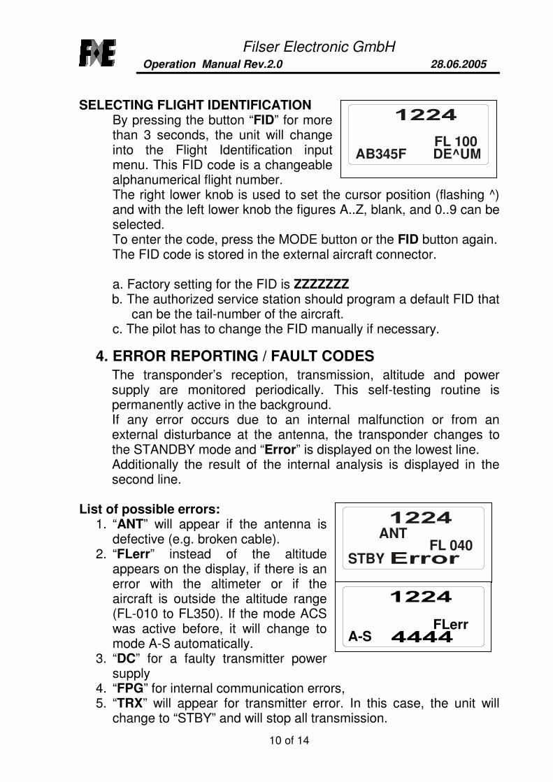
SELECTING FLIGHT IDENTIFICATIONBy pressing the button “FID” for morethan 3 seconds, the unit will changeinto the Flight Identification inputmenu. This FID code is a changeablealphanumerical flight number.The right lower knob is used to set the cursor position (flashing ^)and with the left lower knob the figures A..Z, blank, and 0..9 can beselected.To enter the code, press the MODE button or the FID button again.The FID code is stored in the external aircraft connector.
a. Factory setting for the FID is ZZZZZZZb. The authorized service station should program a default FID that
can be the tail-number of the aircraft.c. The pilot has to change the FID manually if necessary.
4. ERROR REPORTING / FAULT CODES
The transponder’s reception, transmission, altitude and powersupply are monitored periodically. This self-testing routine ispermanently active in the background.If any error occurs due to an internal malfunction or from anexternal disturbance at the antenna, the transponder changes tothe STANDBY mode and “Error” is displayed on the lowest line.Additionally the result of the internal analysis is displayed in thesecond line.
List of possible errors:1. “ANT” will appear if the antenna is
defective (e.g. broken cable).2. “FLerr” instead of the altitude
appears on the display, if there is anerror with the altimeter or if theaircraft is outside the altitude range(FL-010 to FL350). If the mode ACSwas active before, it will change tomode A-S automatically.
3. “DC” for a faulty transmitter powersupply
4. “FPG” for internal communication errors,5. “TRX” will appear for transmitter error. In this case, the unit will
change to “STBY” and will stop all transmission.
FL 040ANT
STBY
FLerrA-S
FL 100AB345F DE^UM

Filser Electronic GmbHOperation Manual Rev.2.0 28.06.2005
11 of 14
To meet ICAO specifications the TRT800/H uses an externalmemory inside the aircraft connector housing of the cable set,which is a part of the aircraft.Because this cable is installed permanentinto the aircraft, a change of thetransponder will not affect the aircraftaddress and the Flight ID. In the eventthere is a Cradle error, (empty memory ordata error) “OUT OF ORDER” will bedisplayed .The first line shows which kind of error is present:Cradle OFF displayed means no or defective data)Cradle Data displayed means digital checksum error.After a few seconds the display shows normal operating conditionbut with inhibited Mode S. The transponder will work with ModeA/C only.You will need to consult an authorized service station to enter theICAO aircraft address (see TRT800/H Installation Manual). Pleaseconsult your airworthiness authority for national procedures.
Note: If no valid ICAO 24 bit aircraft address is programmed to the unit or if thememory is inoperative the transponder will inhibit the Mode S functions. In this caseonly Mode A/C function will be available.
Filser Electronic GmbHOperation Manual Rev.2.0 28.06.2005
12 of 14
5. COMMON AND EMERGENCY ID CODES
The following emergency codes shouldbe noted:
7500 Hijacking7600 Loss of communication7700 Emergency
Common ID Codes:
0022Select in case of VFR flight above5000ft MSL or 3500ft above GND(the higher value counts).
0021Select in case of VFR flight below5000ft MSL (except airfieldpattern).
0032Select in identification areas alongborderlines.
Note: Codes 0022, 0021 and 0031 are country-dependent; pleaseconsult your national airworthiness authority for national procedures.
Filser Electronic GmbHOperation Manual Rev.2.0 28.06.2005
13 of 14
Approval TRT800
Filser Electronic GmbHOperation Manual Rev.2.0 28.06.2005
14 of 14
Approval TRT800H


![[MS-WSPOL]: Web Services: Policy Assertions and WSDL ...... · [WSDL]. processing operation: A WSDL operation that is not a terminating operation. terminating operation: A WSDL operation](https://img.pdfslide.us/doc/110x75/5fee0a69f9c7494e656bdefe/ms-wspol-web-services-policy-assertions-and-wsdl-wsdl-processing.jpg)