Embed Size (px)
Citation preview
Table of Contents
For Training Purposes OnlyMay 03
9-i
FIRE PROTECTIONP I L O T T R A I N I N G G U I D E
Introduction .........................................................................................................................9-1
Engine Fire/Overheat Protection.........................................................................................9-2Description ....................................................................................................................9-2Components and Operation ..........................................................................................9-2
Heat-Sensing Elements ..........................................................................................9-2Fire Detection Control Units ....................................................................................9-4Engine Fire Extinguisher Bottles .............................................................................9-4LH (RH) ENG FIRE PUSH Switch/Lights................................................................9-6BOTTLE 1 (2) ARMED PUSH TO DISCH Switch/Lights ........................................9-6Miscellaneous Test Panel .......................................................................................9-6
Auxiliary Power Unit Fire Protection ...................................................................................9-8Description ....................................................................................................................9-8Components and Operation ..........................................................................................9-8
Heat-Sensing Element ............................................................................................9-8Fire Detection Control Unit ......................................................................................9-9APU Fire Extinguishing Bottle .................................................................................9-9APU FIRE PUSH Switch/Light ..............................................................................9-10APU BOTTLE ARMED PUSH TO DISCH Switch/Light ........................................9-10Miscellaneous Test Panel .....................................................................................9-10
Baggage Compartment Fire Protection ............................................................................9-11Description ..................................................................................................................9-11Components and Operation ........................................................................................9-11
Smoke Detector ....................................................................................................9-11Smoke Detector Test ............................................................................................9-11
Lavatory Fire Protection....................................................................................................9-12Description ..................................................................................................................9-12Components and Operation ........................................................................................9-12
Smoke Detector ....................................................................................................9-12Automatic Fire Extinguisher ..................................................................................9-12
Galley Overheat Protection (Optional) ..............................................................................9-13Description ..................................................................................................................9-13Components and Operation ........................................................................................9-13
Galley Overheat Detector......................................................................................9-13
Portable Fire Extinguishers...............................................................................................9-14Description ..................................................................................................................9-14Components and Operation ........................................................................................9-14
Flight Compartment Fire Extinguisher...................................................................9-14Cabin Fire Extinguisher.........................................................................................9-14
FIRE PROTECTION
9-ii For Training Purposes OnlyMay 03
P I L O T T R A I N I N G G U I D E
Main Landing Gear Bay Overheat Detection System ....................................................... 9-15Description .................................................................................................................. 9-15Components and Operation........................................................................................ 9-15
Heat-Sensing Element .......................................................................................... 9-15Overheat Detection Control Unit ........................................................................... 9-16MLG BAY Overheat Test ...................................................................................... 9-16
Controls and Indicators ..................................................................................................... 9-17General ....................................................................................................................... 9-17Engine and APU Fire/Overheat Protection ................................................................. 9-17Fire Detection and FIREX Monitor Test ...................................................................... 9-18MLG Bay Overheat Test ............................................................................................. 9-18Baggage Smoke Detector Test................................................................................... 9-19EICAS Messages........................................................................................................ 9-20
List of FiguresGraphic Title Figure
For Training Purposes OnlyMay 03
9-iii
FIRE PROTECTIONP I L O T T R A I N I N G G U I D E
Engine Fire Detection .........................................................................................................9-1Jet Pipe / Pylon Overheat Sensing Element .......................................................................9-2Engine and APU Fire Extinguishing System.......................................................................9-3Glareshield Panels..............................................................................................................9-4Miscellaneous Test Panel ...................................................................................................9-5APU Fire Detection .............................................................................................................9-6Copilot’s Glareshield Panel .................................................................................................9-7Smoke Detector Test Button...............................................................................................9-8Main Landing Gear Bay Overheat Heat-Sensing Element .................................................9-9LDG GEAR CONTROL Panel...........................................................................................9-10Glareshield Panels............................................................................................................9-11Miscellaneous Test Panel .................................................................................................9-12Landing Gear Control Panel .............................................................................................9-13Annunciator Panel.............................................................................................................9-14
9-iv For Training Purposes OnlyMay 03
FIRE PROTECTION P I L O T T R A I N I N G G U I D E
Page Intentionally Left Blank
FIRE PROTECTION
For Training Purposes OnlyMay 03
9-1
P I L O T T R A I N I N G G U I D E
CHAPTER 9: FIRE PROTECTION
IntroductionThe fire protection system is divided into two separate subsystems:
• Fire and overheat detection system• Fire extinguishing system
The fire and overheat detection system includes components which detect fire, overheat, or smoke conditions. Fire and overheat detection is provided in the following areas:
• engines• jet pipe and pylons• APU• main landing gear
Smoke detection is provided in the baggage compartment and the lavatory. Provisions are also made for an optional galley overheat detection system.
The fire extinguishing system delivers an extinguishing agent to protected areas of the aircraft; zone A of the engines and the APU enclosure.
The detection and extinguishing systems can be tested and monitored from the cockpit.
Portable fire extinguishers are provided in the cockpit and cabin.
FIRE PROTECTION
9-2 For Training Purposes OnlyMay 03
P I L O T T R A I N I N G G U I D E
Engine Fire/Overheat Protection
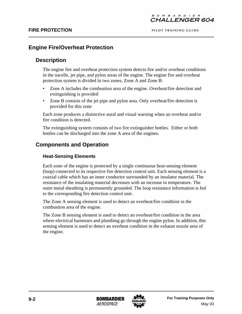
DescriptionThe engine fire and overheat protection system detects fire and/or overheat conditions in the nacelle, jet pipe, and pylon areas of the engine. The engine fire and overheat protection system is divided in two zones, Zone A and Zone B:
• Zone A includes the combustion area of the engine. Overheat/fire detection and extinguishing is provided
• Zone B consists of the jet pipe and pylon area. Only overheat/fire detection is provided for this zone
Each zone produces a distinctive aural and visual warning when an overheat and/or fire condition is detected.
The extinguishing system consists of two fire extinguisher bottles. Either or both bottles can be discharged into the zone A area of the engines.
Components and Operation
Heat-Sensing Elements
Each zone of the engine is protected by a single continuous heat-sensing element (loop) connected to its respective fire detection control unit. Each sensing element is a coaxial cable which has an inner conductor surrounded by an insulator material. The resistance of the insulating material decreases with an increase in temperature. The outer metal sheathing is permanently grounded. The loop resistance information is fed to the corresponding fire detection control unit.
The Zone A sensing element is used to detect an overheat/fire condition in the combustion area of the engine.
The Zone B sensing element is used to detect an overheat/fire condition in the area where electrical harnesses and plumbing go through the engine pylon. In addition, this sensing element is used to detect an overheat condition in the exhaust nozzle area of the engine.
FIRE PROTECTION
For Training Purposes OnlyMay 03
9-3
P I L O T T R A I N I N G G U I D E
Engine Fire Detection Figure 9-1
Jet Pipe / Pylon Overheat Sensing Element Figure 9-2
* NOTE: Only ZONE A can receive Fire Extinguishant
ZONE A
P6
04
_0
9_
00
1
Engine Fire DetectionSensing Elements(Zone A)
Aft Mount Ring
Fire Zone A(Engine Fire Detection)
Fire Zone B(Engine Jet Pipe/Pylon Overheat)
P6
04
_0
9_
00
4
Pylon SensingElement
Engine Jet Pipe(Exhaust Nozzle)Sensing Element
FIRE PROTECTION
9-4 For Training Purposes OnlySept 04
P I L O T T R A I N I N G G U I D E
Fire Detection Control Units
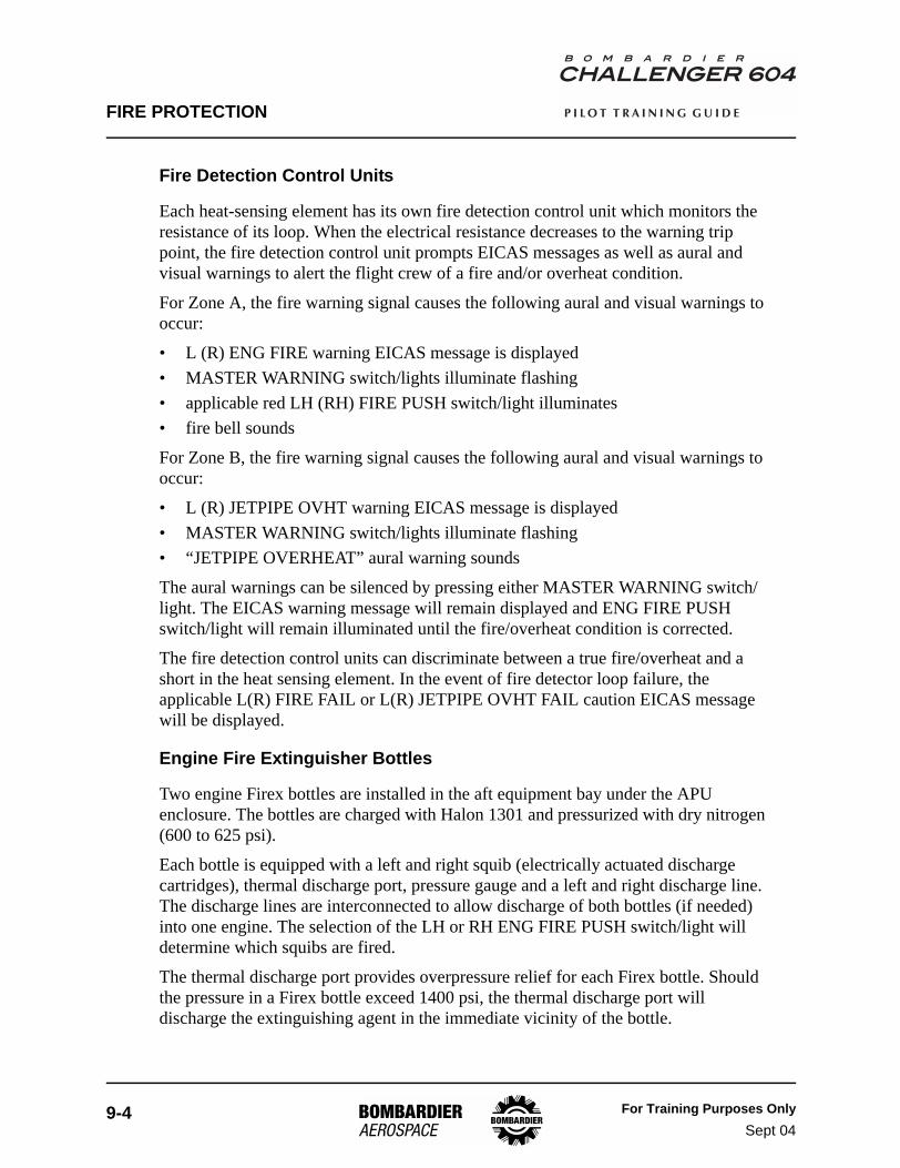
Each heat-sensing element has its own fire detection control unit which monitors the resistance of its loop. When the electrical resistance decreases to the warning trip point, the fire detection control unit prompts EICAS messages as well as aural and visual warnings to alert the flight crew of a fire and/or overheat condition.
For Zone A, the fire warning signal causes the following aural and visual warnings to occur:
• L (R) ENG FIRE warning EICAS message is displayed• MASTER WARNING switch/lights illuminate flashing• applicable red LH (RH) FIRE PUSH switch/light illuminates• fire bell sounds
For Zone B, the fire warning signal causes the following aural and visual warnings to occur:
• L (R) JETPIPE OVHT warning EICAS message is displayed• MASTER WARNING switch/lights illuminate flashing• “JETPIPE OVERHEAT” aural warning sounds
The aural warnings can be silenced by pressing either MASTER WARNING switch/light. The EICAS warning message will remain displayed and ENG FIRE PUSH switch/light will remain illuminated until the fire/overheat condition is corrected.
The fire detection control units can discriminate between a true fire/overheat and a short in the heat sensing element. In the event of fire detector loop failure, the applicable L(R) FIRE FAIL or L(R) JETPIPE OVHT FAIL caution EICAS message will be displayed.
Engine Fire Extinguisher Bottles
Two engine Firex bottles are installed in the aft equipment bay under the APU enclosure. The bottles are charged with Halon 1301 and pressurized with dry nitrogen (600 to 625 psi).
Each bottle is equipped with a left and right squib (electrically actuated discharge cartridges), thermal discharge port, pressure gauge and a left and right discharge line. The discharge lines are interconnected to allow discharge of both bottles (if needed) into one engine. The selection of the LH or RH ENG FIRE PUSH switch/light will determine which squibs are fired.
The thermal discharge port provides overpressure relief for each Firex bottle. Should the pressure in a Firex bottle exceed 1400 psi, the thermal discharge port will discharge the extinguishing agent in the immediate vicinity of the bottle.
FIRE PROTECTION
For Training Purposes OnlySept 04
9-5
P I L O T T R A I N I N G G U I D E
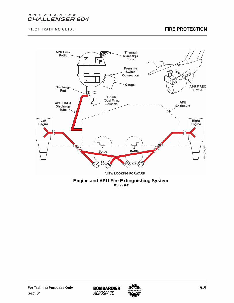
Engine and APU Fire Extinguishing System Figure 9-3
APU FirexBottle
ThermalDischarge
Tube
PressureSwitch
Connection
DischargePort
APU FIREXDischarge
Tube
APU FIREXBottle
1Bottle
APUEnclosure
VIEW LOOKING FORWARD
P6
04
_0
9_
00
3
2Bottle
LeftEngine
RightEngine
Squib(Dual FiringElements)
Gauge
FIRE PROTECTION
9-6 For Training Purposes OnlyMay 03
P I L O T T R A I N I N G G U I D E
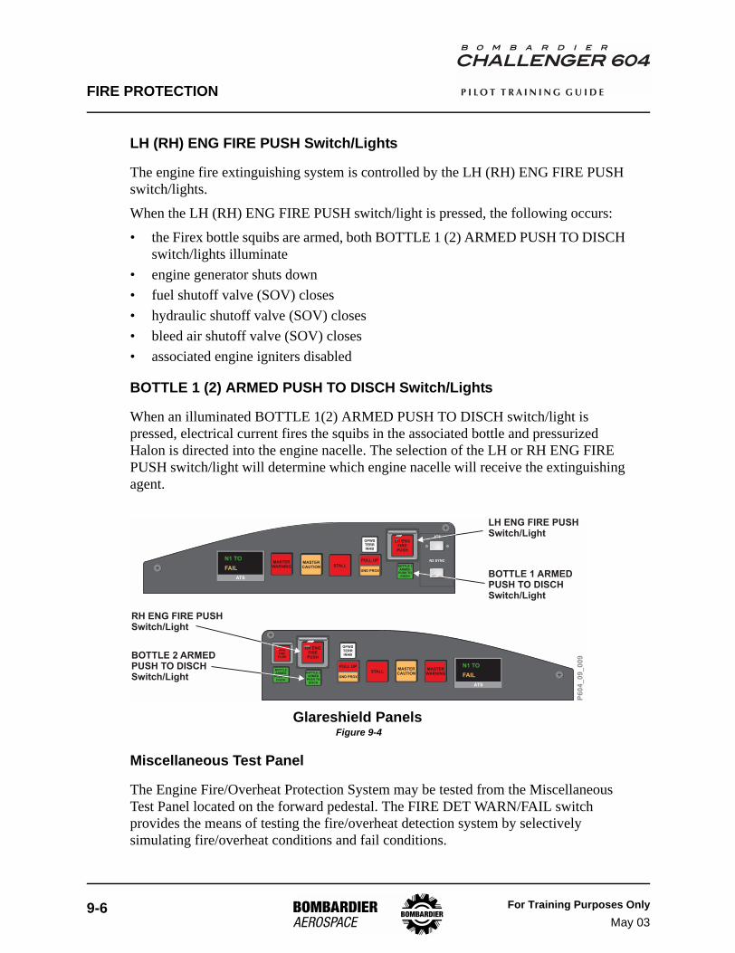
LH (RH) ENG FIRE PUSH Switch/Lights
The engine fire extinguishing system is controlled by the LH (RH) ENG FIRE PUSH switch/lights.
When the LH (RH) ENG FIRE PUSH switch/light is pressed, the following occurs:
• the Firex bottle squibs are armed, both BOTTLE 1 (2) ARMED PUSH TO DISCH switch/lights illuminate
• engine generator shuts down• fuel shutoff valve (SOV) closes• hydraulic shutoff valve (SOV) closes• bleed air shutoff valve (SOV) closes• associated engine igniters disabled
BOTTLE 1 (2) ARMED PUSH TO DISCH Switch/Lights
When an illuminated BOTTLE 1(2) ARMED PUSH TO DISCH switch/light is pressed, electrical current fires the squibs in the associated bottle and pressurized Halon is directed into the engine nacelle. The selection of the LH or RH ENG FIRE PUSH switch/light will determine which engine nacelle will receive the extinguishing agent.
Glareshield Panels Figure 9-4
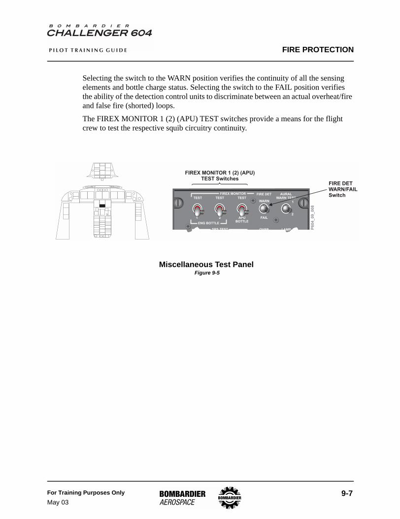
Miscellaneous Test Panel
The Engine Fire/Overheat Protection System may be tested from the Miscellaneous Test Panel located on the forward pedestal. The FIRE DET WARN/FAIL switch provides the means of testing the fire/overheat detection system by selectively simulating fire/overheat conditions and fail conditions.
LH ENGFIREPUSH
GPWSTERRINHB
MASTERWARNING BOTTLE 1
ARMEDPUSH TO
DISCH
STALLMASTERCAUTION
PULL UP
GND PROX
ATS
N2 SYNC
ATS
N1 TO
FAIL
ATS
N1 TO
FAIL
APUFIREPUSH
RH ENGFIREPUSH
GPWSTERRINHB
MASTERWARNINGBOTTLE 2
ARMEDPUSH TO
DISCH
BOTTLEARMED
PUSH TODISCH
STALLMASTERCAUTION
PULL UP
GND PROX
LH ENG FIRE PUSHSwitch/Light
BOTTLE 1 ARMEDPUSH TO DISCHSwitch/Light
RH ENG FIRE PUSHSwitch/Light
BOTTLE 2 ARMEDPUSH TO DISCHSwitch/Light
P6
04
_0
9_
00
9
FIRE PROTECTION
For Training Purposes OnlyMay 03
9-7
P I L O T T R A I N I N G G U I D E
Selecting the switch to the WARN position verifies the continuity of all the sensing elements and bottle charge status. Selecting the switch to the FAIL position verifies the ability of the detection control units to discriminate between an actual overheat/fire and false fire (shorted) loops.
The FIREX MONITOR 1 (2) (APU) TEST switches provide a means for the flight crew to test the respective squib circuitry continuity.
Miscellaneous Test Panel Figure 9-5
TEST
TEST
TEST
TEST
TESTWARN
TEST
FIRE DET
1 2 APUBOTTLE
FAIL
SPS TEST
FIREX MONITOR AURALWARN TEST
LAMPTEST
OVSPTEST
1
2
ENG BOTTLE
FIREX MONITOR 1 (2) (APU)TEST Switches
FIRE DETWARN/FAILSwitch
P6
04
_0
9_
00
8
FIRE PROTECTION
9-8 For Training Purposes OnlyMay 03
P I L O T T R A I N I N G G U I D E
Auxiliary Power Unit Fire Protection
DescriptionThe APU fire detection system is used to detect an overheat/fire condition within the APU enclosure. The fire detection system continuously monitors the APU. If a fire or overheat condition is detected, the APU will automatically shut down and an EICAS message as well as an aural and visual warning will occur. The APU fire extinguishing system consists of one fire extinguisher bottle.
Components and Operation
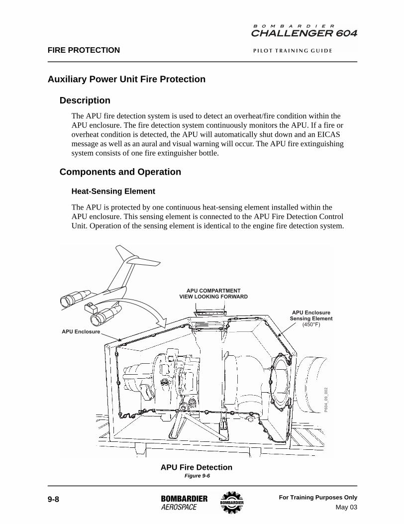
Heat-Sensing Element
The APU is protected by one continuous heat-sensing element installed within the APU enclosure. This sensing element is connected to the APU Fire Detection Control Unit. Operation of the sensing element is identical to the engine fire detection system.
APU Fire Detection Figure 9-6
APU EnclosureSensing Element
(450°F)
APU COMPARTMENTVIEW LOOKING FORWARD
P6
04
_0
9_
00
2
APU Enclosure
FIRE PROTECTION
For Training Purposes OnlyMay 03
9-9
P I L O T T R A I N I N G G U I D E
Fire Detection Control Unit
The APU has a dedicated fire detection control unit which continuously monitors the resistance of its own loop. When the electrical resistance decreases to the warning trip point, the unit produces a fire warning signal to the EICAS which causes the following aural and visual warnings to occur:
• APU FIRE warning EICAS message is displayed• MASTER WARNING switch/lights illuminate flashing• fire bell sounds• APU FIRE PUSH switch/light illuminates
The APU will also shut down automatically.
The aural warnings can be silenced by pressing either MASTER WARNING switch/light. However, the EICAS warning message will remain displayed and APU FIRE PUSH switch/light will remain illuminated until the fire/overheat condition is corrected.
As with the engine fire-sensing elements, the APU fire detection control unit can discriminate between an actual fire/overheat and a false fire (i.e., short in the sensing element). In the event of APU fire detector loop failure, the APU FIRE FAIL caution EICAS message will be displayed.
APU Fire Extinguishing Bottle
APU fire extinguishing is provided by one Firex bottle located adjacent to the APU compartment in the aft equipment bay. The bottle is charged with Halon 1301 and pressurized with dry nitrogen (600 to 625 psi).
The APU Firex bottle is equipped with a pressure gauge and a thermal discharge port and is connected by a single tube to the APU compartment. The pressurized extinguishing agent is discharged by a squib with dual firing cartridges, for redundancy.
The thermal discharge port provides overpressure relief. Operation is identical to the engine Firex bottles.
FIRE PROTECTION
9-10 For Training Purposes OnlyMay 03
P I L O T T R A I N I N G G U I D E
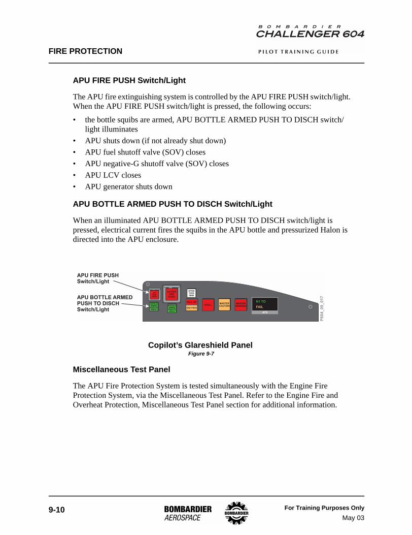
APU FIRE PUSH Switch/Light
The APU fire extinguishing system is controlled by the APU FIRE PUSH switch/light. When the APU FIRE PUSH switch/light is pressed, the following occurs:
• the bottle squibs are armed, APU BOTTLE ARMED PUSH TO DISCH switch/light illuminates
• APU shuts down (if not already shut down)• APU fuel shutoff valve (SOV) closes• APU negative-G shutoff valve (SOV) closes• APU LCV closes• APU generator shuts down
APU BOTTLE ARMED PUSH TO DISCH Switch/Light
When an illuminated APU BOTTLE ARMED PUSH TO DISCH switch/light is pressed, electrical current fires the squibs in the APU bottle and pressurized Halon is directed into the APU enclosure.
Copilot’s Glareshield Panel Figure 9-7
Miscellaneous Test Panel
The APU Fire Protection System is tested simultaneously with the Engine Fire Protection System, via the Miscellaneous Test Panel. Refer to the Engine Fire and Overheat Protection, Miscellaneous Test Panel section for additional information.
ATS
N1 TO
FAIL
APUFIREPUSH
RH ENGFIREPUSH
GPWSTERRINHB
MASTERWARNINGBOTTLE 2
ARMEDPUSH TO
DISCH
BOTTLEARMED
PUSH TODISCH
STALLMASTERCAUTION
PULL UP
GND PROX
APU FIRE PUSHSwitch/Light
APU BOTTLE ARMEDPUSH TO DISCHSwitch/Light
P6
04
_0
9_
01
7
FIRE PROTECTION
For Training Purposes OnlyMay 03
9-11
P I L O T T R A I N I N G G U I D E
Baggage Compartment Fire Protection
DescriptionFire protection for the baggage compartment consists of an electronic smoke detector that interfaces with the EICAS to provide aural and visual warnings.
Components and Operation
Smoke Detector
The aircraft is equipped with a smoke detection system for the baggage compartment. When the smoke density reaches a predetermined level, the smoke detector produces a fire warning signal which causes the following aural and visual warnings to occur:
• SMOKE BAGGAGE BAY warning EICAS message is displayed• MASTER WARNING switch/lights illuminate flashing• “SMOKE” aural warning sounds
The aural warning can be silenced by pressing either MASTER WARNING switch/light. However, the EICAS warning message will remain displayed until the unit resets itself.
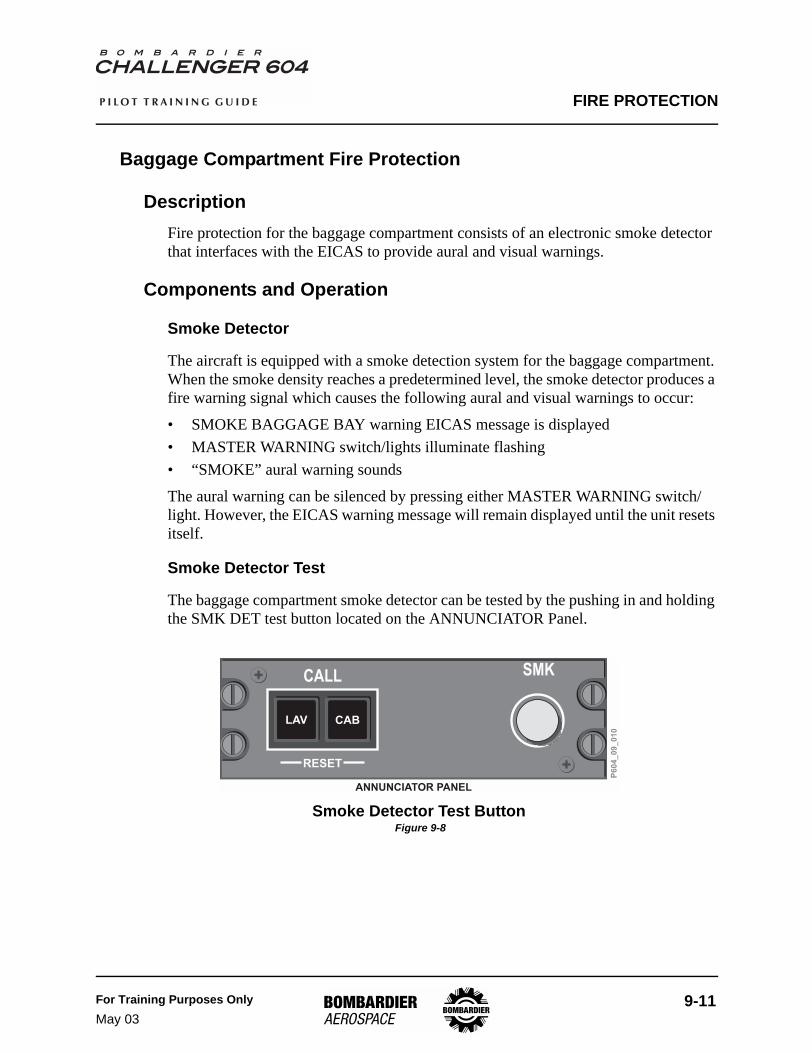
Smoke Detector Test
The baggage compartment smoke detector can be tested by the pushing in and holding the SMK DET test button located on the ANNUNCIATOR Panel.
Smoke Detector Test Button Figure 9-8
ANNUNCIATOR PANEL
P6
04
_0
9_
01
0
RESET
CALL SMK
CABLAV
FIRE PROTECTION
9-12 For Training Purposes OnlyMay 03
P I L O T T R A I N I N G G U I D E
Lavatory Fire Protection
DescriptionFire protection for the lavatory consists of an electronic smoke detector that interfaces with the EICAS to provide aural and visual warnings and an independent fire extinguisher that operates automatically in the waste container.
Components and Operation
Smoke Detector
The aircraft is equipped with a smoke detection system in the lavatory. When the smoke density reaches a predetermined level, the smoke detector produces a signal to the EICAS to alert the crew and sounds an aural alarm in the lavatory. The lavatory smoke warning signal causes the following aural and visual warnings to occur:
• SMOKE TOILET warning EICAS message is displayed• MASTER WARNING switch/lights illuminate flashing• “SMOKE” aural warning sounds
The aural warning can be silenced by pressing either MASTER WARNING switch/light. However, the EICAS warning message will remain displayed until the unit resets itself.
Automatic Fire Extinguisher
In the event of a fire in the lavatory waste container, automatic fire extinguishing is provided. The bottle is mounted on a bracket beside the waste container. Once the temperature reaches a predetermined level, two heat-sensitive capsules melt and release Halon 1211 into the waste container. (Individual aircraft installations may vary, consult Completion Center documentation for aircraft-specific information.)
FIRE PROTECTION
For Training Purposes OnlyMay 03
9-13
P I L O T T R A I N I N G G U I D E
Galley Overheat Protection (Optional)
DescriptionOverheat protection for the galley consists of an optional overheat detection system that interfaces with the EICAS to provide aural and visual warnings.
Components and Operation
Galley Overheat Detector
When the temperature reaches a predetermined level, the overheat detector provides a signal to the EICAS to alert the crew of a galley overheat. The galley overheat alert signal causes the following aural and visual warnings to occur:
• GALLEY OVHT warning EICAS message is displayed• MASTER WARNING switch/lights illuminate flashing• a triple attenson sounds
The aural warning can be silenced by pressing either MASTER WARNING switch/light. However, the EICAS warning message will remain displayed until the unit resets itself.
FIRE PROTECTION
9-14 For Training Purposes OnlyJan 04
P I L O T T R A I N I N G G U I D E
Portable Fire Extinguishers
DescriptionPortable Halon 1211 fire extinguishers are provided in both the flight compartment and the cabin to fight a fire occurring inside the aircraft. Halon 1211 is effective in fighting Class A, B and C fires.
Components and Operation
Flight Compartment Fire Extinguisher
The flight compartment fire extinguisher is installed behind the copilot’s seat. Discharging of the Halon is effected by squeezing a spring-loaded lever.
IF A FIRE EXTINGUISHER IS TO BE DISCHARGED IN THE FLIGHT COMPARTMENT, ALL FLIGHT CREW MUST WEAR OXYGEN MASKS WITH EMERGENCY SELECTED (100% OXYGEN).
CREW EXPOSURE TO HIGH LEVELS OF HALON VAPORS MAY RESULT IN DIZZINESS, IMPAIRED COORDINATION, AND REDUCED MENTAL SHARPNESS.
Cabin Fire Extinguisher
The cabin fire extinguisher is installed during completion and its location may vary depending on the interior configuration. Consult the aircraft Completion Center manual for the specific location(s). Operation is identical to the Flight Compartment fire extinguisher.
WARNING
FIRE PROTECTION
For Training Purposes OnlySept 04
9-15
P I L O T T R A I N I N G G U I D E
Main Landing Gear Bay Overheat Detection System
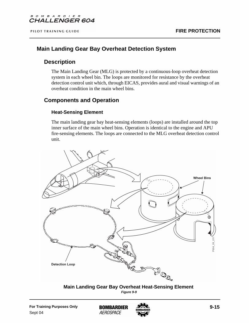
DescriptionThe Main Landing Gear (MLG) is protected by a continuous-loop overheat detection system in each wheel bin. The loops are monitored for resistance by the overheat detection control unit which, through EICAS, provides aural and visual warnings of an overheat condition in the main wheel bins.
Components and Operation
Heat-Sensing Element
The main landing gear bay heat-sensing elements (loops) are installed around the top inner surface of the main wheel bins. Operation is identical to the engine and APU fire-sensing elements. The loops are connected to the MLG overheat detection control unit.
Main Landing Gear Bay Overheat Heat-Sensing Element Figure 9-9
P6
04
_0
9_
011
Wheel Bins
Detection Loop
FIRE PROTECTION
9-16 For Training Purposes OnlyMay 03
P I L O T T R A I N I N G G U I D E
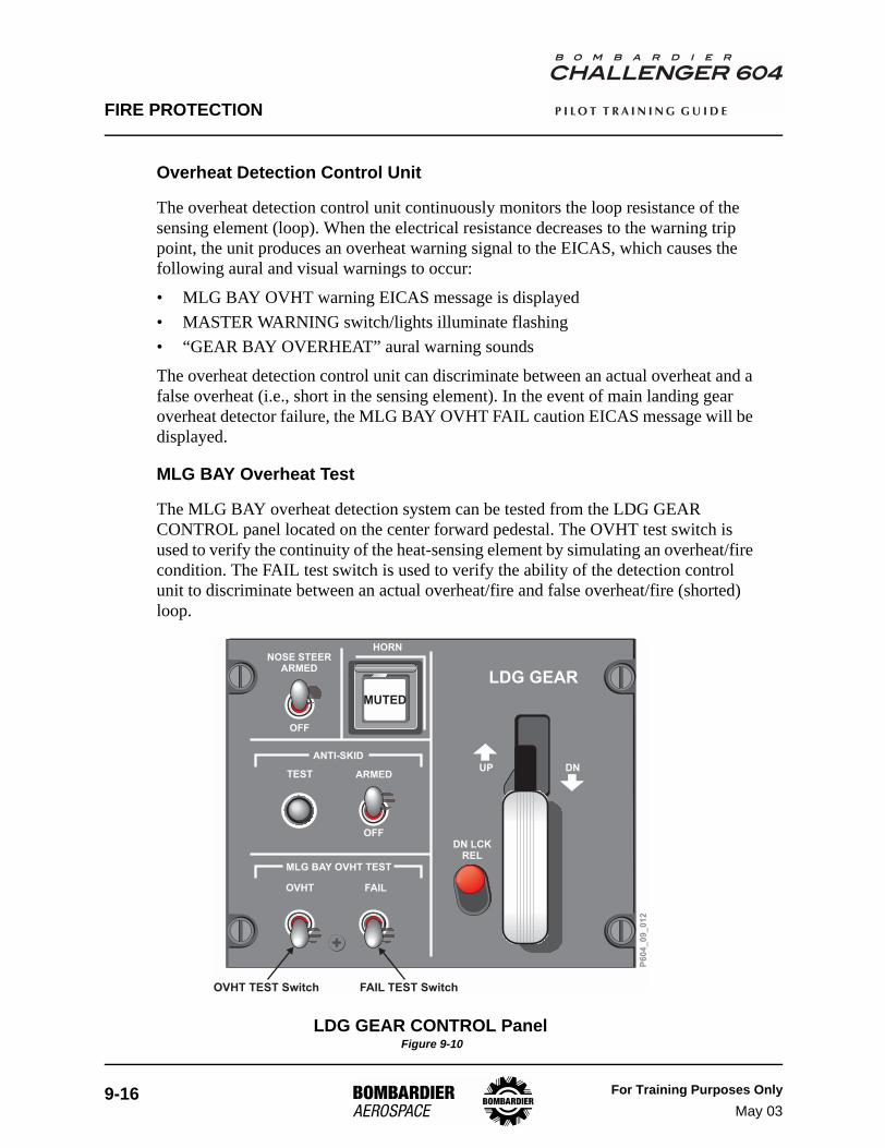
Overheat Detection Control Unit
The overheat detection control unit continuously monitors the loop resistance of the sensing element (loop). When the electrical resistance decreases to the warning trip point, the unit produces an overheat warning signal to the EICAS, which causes the following aural and visual warnings to occur:
• MLG BAY OVHT warning EICAS message is displayed• MASTER WARNING switch/lights illuminate flashing• “GEAR BAY OVERHEAT” aural warning sounds
The overheat detection control unit can discriminate between an actual overheat and a false overheat (i.e., short in the sensing element). In the event of main landing gear overheat detector failure, the MLG BAY OVHT FAIL caution EICAS message will be displayed.
MLG BAY Overheat Test
The MLG BAY overheat detection system can be tested from the LDG GEAR CONTROL panel located on the center forward pedestal. The OVHT test switch is used to verify the continuity of the heat-sensing element by simulating an overheat/fire condition. The FAIL test switch is used to verify the ability of the detection control unit to discriminate between an actual overheat/fire and false overheat/fire (shorted) loop.
LDG GEAR CONTROL Panel Figure 9-10
MUTED
OFF
TEST
MLG BAY OVHT TEST
OVHT FAIL
UP DN
LDG GEAR
DN LCKREL
ANTI-SKID
ARMED
NOSE STEERARMED
HORN
OFF
OVHT TEST Switch FAIL TEST Switch
P6
04
_0
9_
01
2
FIRE PROTECTION
For Training Purposes OnlyMay 03
9-17
P I L O T T R A I N I N G G U I D E
Controls and Indicators
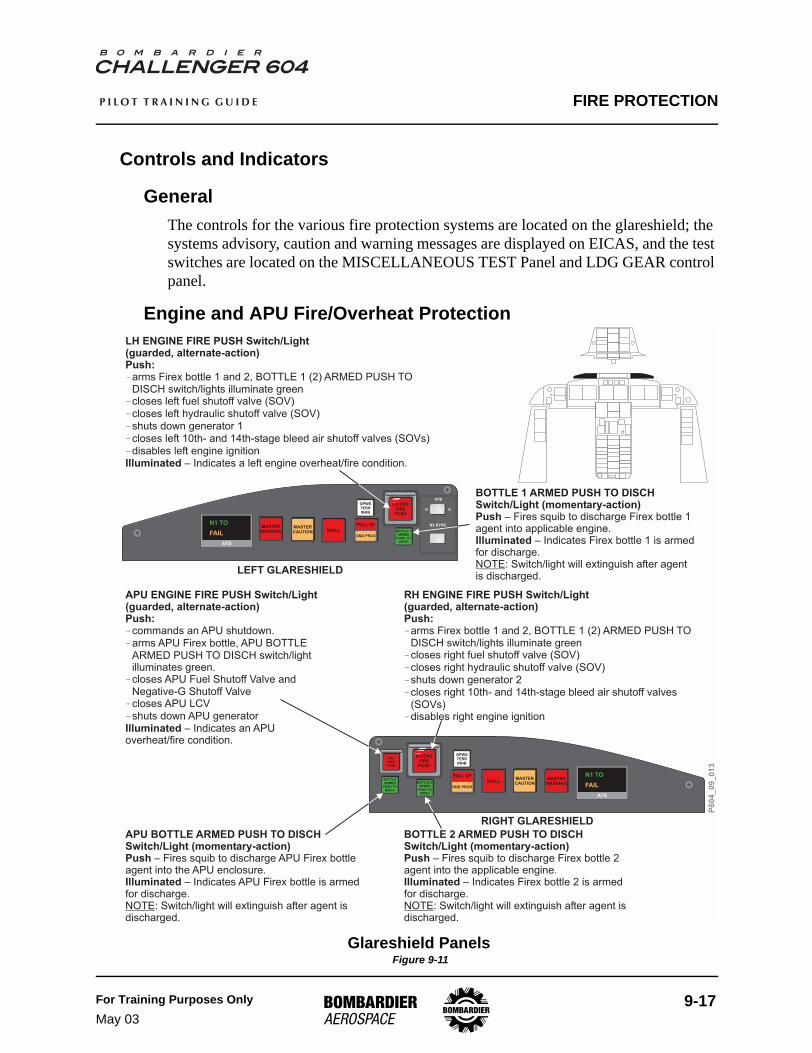
GeneralThe controls for the various fire protection systems are located on the glareshield; the systems advisory, caution and warning messages are displayed on EICAS, and the test switches are located on the MISCELLANEOUS TEST Panel and LDG GEAR control panel.
Engine and APU Fire/Overheat Protection
Glareshield Panels Figure 9-11
ATS
N1 TO
FAIL
APUFIREPUSH
RH ENGFIREPUSH
GPWSTERRINHB
MASTERWARNINGBOTTLE 2
ARMEDPUSH TO
DISCH
BOTTLEARMED
PUSH TODISCH
STALLMASTERCAUTION
PULL UP
GND PROX
LH ENGFIREPUSH
GPWSTERRINHB
MASTERWARNING BOTTLE 1
ARMEDPUSH TO
DISCH
STALLMASTERCAUTION
PULL UP
GND PROX
ATS
N2 SYNC
ATS
N1 TO
FAIL
LH ENGINE FIRE PUSH Switch/Light(guarded, alternate-action)Push:
Illuminated
�
�
�
�
�
�
arms Firex bottle 1 and 2, BOTTLE 1 (2) ARMED PUSH TODISCH switch/lights illuminate greencloses left fuel shutoff valve (SOV)closes left hydraulic shutoff valve (SOV)shuts down generator 1closes left 10th- and 14th-stage bleed air shutoff valves (SOVs)disables left engine ignition
– Indicates a left engine overheat/fire condition.
BOTTLE 1 ARMED PUSH TO DISCHSwitch/Light (momentary-action)Push
Illuminated
– Fires squib to discharge Firex bottle 1agent into applicable engine.
– Indicates Firex bottle 1 is armedfor discharge.
: Switch/light will extinguish after agentis discharged.NOTE
BOTTLE 2 ARMED PUSH TO DISCHSwitch/Light (momentary-action)Push
Illuminated
– Fires squib to discharge Firex bottle 2agent into the applicable engine.
– Indicates Firex bottle 2 is armedfor discharge.
: Switch/light will extinguish after agent isdischarged.NOTE
RH ENGINE FIRE PUSH Switch/Light(guarded, alternate-action)Push:�
�
�
�
�
�
arms Firex bottle 1 and 2, BOTTLE 1 (2) ARMED PUSH TODISCH switch/lights illuminate greencloses right fuel shutoff valve (SOV)closes right hydraulic shutoff valve (SOV)shuts down generator 2closes right 10th- and 14th-stage bleed air shutoff valves(SOVs)disables right engine ignition
P6
04
_0
9_
01
3
APU ENGINE FIRE PUSH Switch/Light(guarded, alternate-action)Push:
Illuminated
�
�
�
�
�
commands an APU shutdown.arms APU Firex bottle, APU BOTTLEARMED PUSH TO DISCH switch/lightilluminates green.closes APU Fuel Shutoff Valve andNegative-G Shutoff Valvecloses APU LCVshuts down APU generator
– Indicates an APUoverheat/fire condition.
APU BOTTLE ARMED PUSH TO DISCHSwitch/Light (momentary-action)Push
Illuminated
– Fires squib to discharge APU Firex bottleagent into the APU enclosure.
– Indicates APU Firex bottle is armedfor discharge.
: Switch/light will extinguish after agent isdischarged.NOTE
LEFT GLARESHIELD
RIGHT GLARESHIELD
FIRE PROTECTION
9-18 For Training Purposes OnlyMay 03
P I L O T T R A I N I N G G U I D E
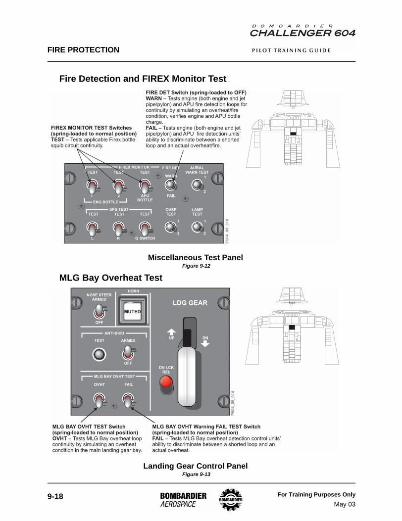
Fire Detection and FIREX Monitor Test
Miscellaneous Test Panel Figure 9-12
MLG Bay Overheat Test
Landing Gear Control Panel Figure 9-13
TEST
TEST
TEST
TEST
TESTWARN
TEST
FIRE DET
1 2 APUBOTTLE
FAIL
L R G SWITCH
SPS TEST
FIREX MONITOR AURALWARN TEST
LAMPTEST
OVSPTEST
1
2
1
2
1
2
ENG BOTTLE
P6
04
_0
9_
01
8
FIREX MONITOR TEST Switches(spring-loaded to normal position)TEST – Tests applicable Firex bottlesquib circuit continuity.
FIRE DET Switch (spring-loaded to OFF)WARN
FAIL
– Tests engine (both engine and jetpipe/pylon) and APU fire detection loops forcontinuity by simulating an overheat/firecondition, verifies engine and APU bottlecharge.
– Tests engine (both engine and jetpipe/pylon) and APU fire detection units’ability to discriminate between a shortedloop and an actual overheat/fire.
MUTED
OFF
TEST
MLG BAY OVHT TEST
OVHT FAIL
UP DN
LDG GEAR
DN LCKREL
ANTI-SKID
ARMED
NOSE STEERARMED
HORN
OFF
P6
04
_0
9_
01
4
MLG BAY OVHT TEST Switch(spring-loaded to normal position)OVHT – Tests MLG Bay overheat loopcontinuity by simulating an overheatcondition in the main landing gear bay.
MLG BAY OVHT Warning FAIL TEST Switch(spring-loaded to normal position)FAIL – Tests MLG Bay overheat detection control units’ability to discriminate between a shorted loop and anactual overheat.
FIRE PROTECTION
For Training Purposes OnlyMay 03
9-19
P I L O T T R A I N I N G G U I D E
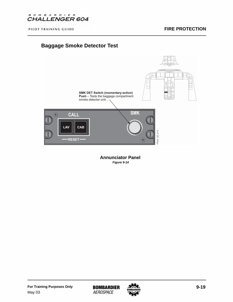
Baggage Smoke Detector Test
Annunciator Panel Figure 9-14
RESET
CALL SMK
CABLAV
P6
04
_0
9_
01
5
SMK DET Switch (momentary-action)Push – Tests the baggage compartmentsmoke detector unit.
FIRE PROTECTION
9-20 For Training Purposes OnlyJan 04
P I L O T T R A I N I N G G U I D E
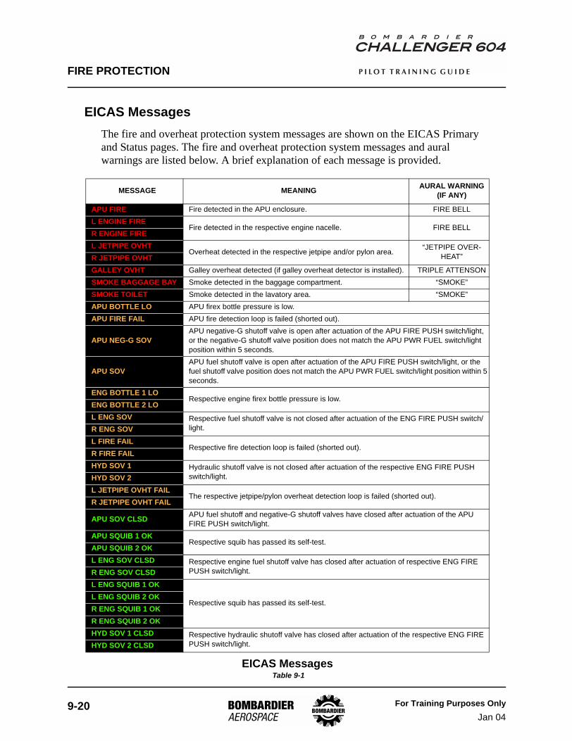
EICAS MessagesThe fire and overheat protection system messages are shown on the EICAS Primary and Status pages. The fire and overheat protection system messages and aural warnings are listed below. A brief explanation of each message is provided.
MESSAGE MEANING AURAL WARNING(IF ANY)
APU FIRE Fire detected in the APU enclosure. FIRE BELLL ENGINE FIRE
Fire detected in the respective engine nacelle. FIRE BELLR ENGINE FIREL JETPIPE OVHT
Overheat detected in the respective jetpipe and/or pylon area. “JETPIPE OVER-HEAT”R JETPIPE OVHT
GALLEY OVHT Galley overheat detected (if galley overheat detector is installed). TRIPLE ATTENSONSMOKE BAGGAGE BAY Smoke detected in the baggage compartment. “SMOKE”SMOKE TOILET Smoke detected in the lavatory area. “SMOKE”APU BOTTLE LO APU firex bottle pressure is low.APU FIRE FAIL APU fire detection loop is failed (shorted out).
APU NEG-G SOVAPU negative-G shutoff valve is open after actuation of the APU FIRE PUSH switch/light, or the negative-G shutoff valve position does not match the APU PWR FUEL switch/light position within 5 seconds.
APU SOVAPU fuel shutoff valve is open after actuation of the APU FIRE PUSH switch/light, or the fuel shutoff valve position does not match the APU PWR FUEL switch/light position within 5 seconds.
ENG BOTTLE 1 LORespective engine firex bottle pressure is low.
ENG BOTTLE 2 LOL ENG SOV Respective fuel shutoff valve is not closed after actuation of the ENG FIRE PUSH switch/
light.R ENG SOVL FIRE FAIL
Respective fire detection loop is failed (shorted out).R FIRE FAILHYD SOV 1 Hydraulic shutoff valve is not closed after actuation of the respective ENG FIRE PUSH
switch/light.HYD SOV 2L JETPIPE OVHT FAIL
The respective jetpipe/pylon overheat detection loop is failed (shorted out).R JETPIPE OVHT FAIL
APU SOV CLSD APU fuel shutoff and negative-G shutoff valves have closed after actuation of the APU FIRE PUSH switch/light.
APU SQUIB 1 OKRespective squib has passed its self-test.
APU SQUIB 2 OKL ENG SOV CLSD Respective engine fuel shutoff valve has closed after actuation of respective ENG FIRE
PUSH switch/light.R ENG SOV CLSDL ENG SQUIB 1 OK
Respective squib has passed its self-test.L ENG SQUIB 2 OKR ENG SQUIB 1 OKR ENG SQUIB 2 OKHYD SOV 1 CLSD Respective hydraulic shutoff valve has closed after actuation of the respective ENG FIRE
PUSH switch/light.HYD SOV 2 CLSD
EICAS Messages Table 9-1


![Fire Protection - SmartCockpit A319-320-321 [Fire Protection] Page 1. Airbus A319-320-321 [Fire Protection] ... [Fire Protection] Page 46. Airbus A319-320-321 [Fire Protection] Page](https://img.pdfslide.us/doc/110x75/5aaae6367f8b9a6c188ed0d4/fire-protection-a319-320-321-fire-protection-page-1-airbus-a319-320-321-fire.jpg)