Embed Size (px)
Citation preview
1
Pilot-Scale Evaluation of an Advanced Carbon Sorbent-Based Process for Post-Combustion Carbon Capture
Kickoff MeetingDecember 4, 2013, Pittsburgh, PA.
2
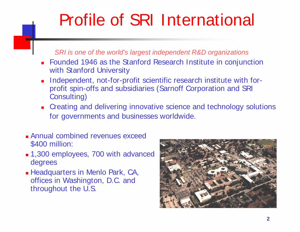
Profile of SRI International
SRI is one of the world’s largest independent R&D organizations Founded 1946 as the Stanford Research Institute in conjunction
with Stanford University Independent, not-for-profit scientific research institute with for-
profit spin-offs and subsidiaries (Sarnoff Corporation and SRI Consulting)
Creating and delivering innovative science and technology solutions for governments and businesses worldwide.
Annual combined revenues exceed $400 million:
1,300 employees, 700 with advanced degrees
Headquarters in Menlo Park, CA, offices in Washington, D.C. and throughout the U.S.
3
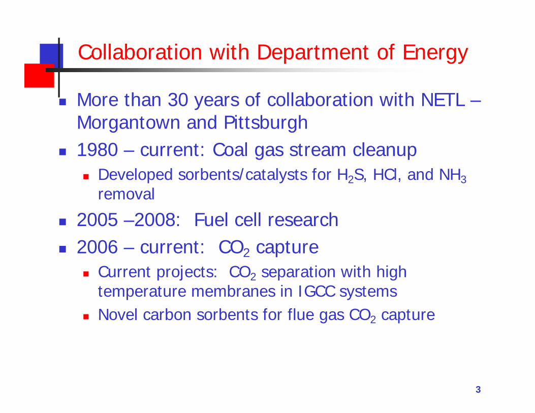
Collaboration with Department of Energy
More than 30 years of collaboration with NETL –Morgantown and Pittsburgh
1980 – current: Coal gas stream cleanup Developed sorbents/catalysts for H2S, HCl, and NH3
removal
2005 –2008: Fuel cell research 2006 – current: CO2 capture
Current projects: CO2 separation with high temperature membranes in IGCC systems
Novel carbon sorbents for flue gas CO2 capture
The Linde Group Overview and Carbon Capture Expertise
4
5
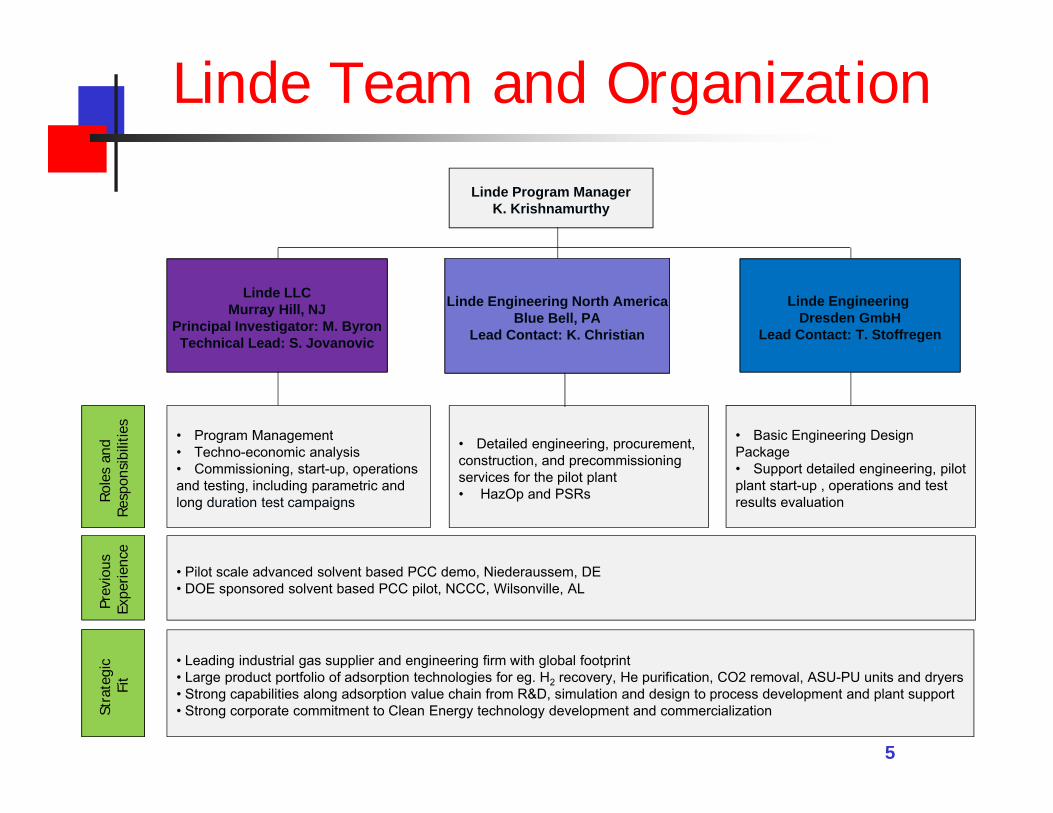
Linde Team and Organization
Linde LLCMurray Hill, NJ
Principal Investigator: M. ByronTechnical Lead: S. Jovanovic
• Basic Engineering DesignPackage• Support detailed engineering, pilotplant start-up , operations and testresults evaluation
• Program Management• Techno-economic analysis• Commissioning, start-up, operationsand testing, including parametric andlong duration test campaigns
• Detailed engineering, procurement,construction, and precommissioningservices for the pilot plant• HazOp and PSRs
Linde Program ManagerK. Krishnamurthy
Linde Engineering North AmericaBlue Bell, PA
Lead Contact: K. Christian
Linde Engineering Dresden GmbH
Lead Contact: T. Stoffregen
Role
s an
d Re
spon
sibi
litie
s
• Pilot scale advanced solvent based PCC demo, Niederaussem, DE• DOE sponsored solvent based PCC pilot, NCCC, Wilsonville, AL
Prev
ious
Ex
perie
nce
• Leading industrial gas supplier and engineering firm with global footprint• Large product portfolio of adsorption technologies for eg. H2 recovery, He purification, CO2 removal, ASU-PU units and dryers• Strong capabilities along adsorption value chain from R&D, simulation and design to process development and plant support• Strong corporate commitment to Clean Energy technology development and commercializationSt
rate
gic
Fit
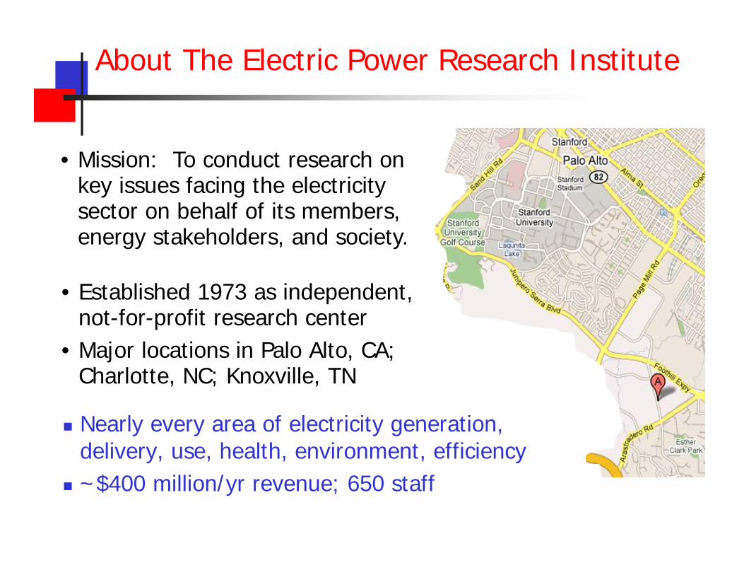
About The Electric Power Research Institute
• Established 1973 as independent, not-for-profit research center
• Major locations in Palo Alto, CA; Charlotte, NC; Knoxville, TN
Nearly every area of electricity generation, delivery, use, health, environment, efficiency
~$400 million/yr revenue; 650 staff
• Mission: To conduct research on key issues facing the electricity sector on behalf of its members, energy stakeholders, and society.
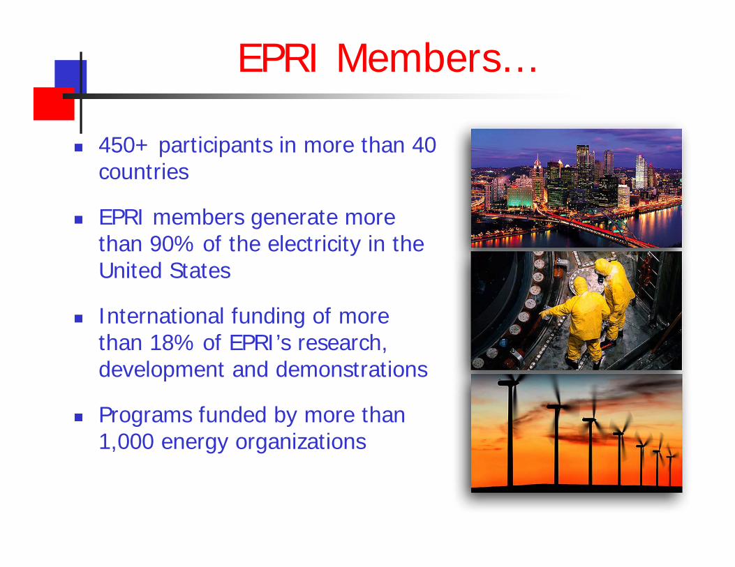
EPRI Members…
450+ participants in more than 40 countries
EPRI members generate more than 90% of the electricity in the United States
International funding of more than 18% of EPRI’s research, development and demonstrations
Programs funded by more than 1,000 energy organizations
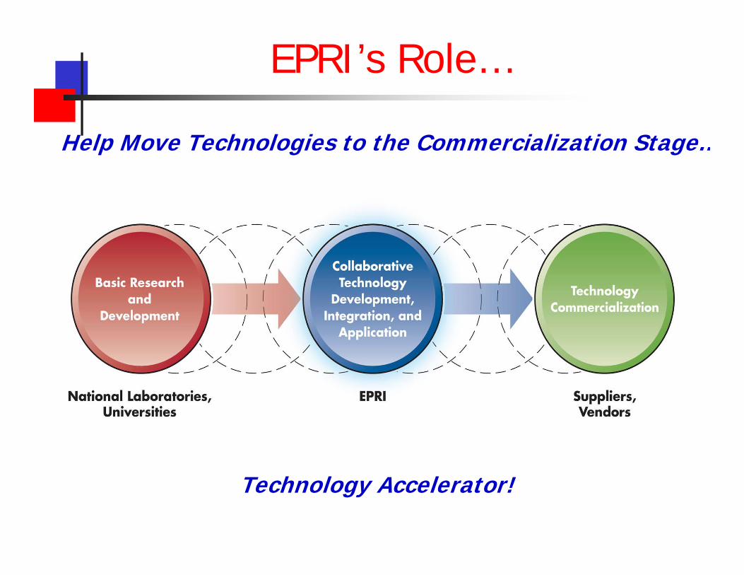
Help Move Technologies to the Commercialization Stage…
EPRI’s Role…
Technology Accelerator!
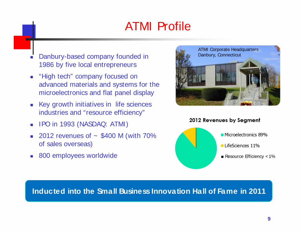
ATMI Profile
Danbury-based company founded in 1986 by five local entrepreneurs
“High tech” company focused on advanced materials and systems for the microelectronics and flat panel display
Key growth initiatives in life sciences industries and “resource efficiency”
IPO in 1993 (NASDAQ: ATMI)
2012 revenues of ~ $400 M (with 70% of sales overseas)
800 employees worldwide
9
ATMI Corporate HeadquartersDanbury, Connecticut
Inducted into the Small Business Innovation Hall of Fame in 2011
■ Resource Efficiency <1%
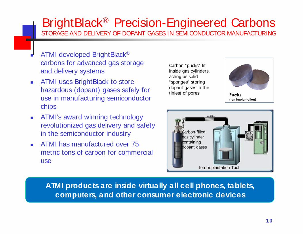
BrightBlack® Precision-Engineered CarbonsSTORAGE AND DELIVERY OF DOPANT GASES IN SEMICONDUCTOR MANUFACTURING
ATMI developed BrightBlack®
carbons for advanced gas storage and delivery systems
ATMI uses BrightBlack to store hazardous (dopant) gases safely for use in manufacturing semiconductor chips
ATMI’s award winning technology revolutionized gas delivery and safety in the semiconductor industry
ATMI has manufactured over 75 metric tons of carbon for commercial use
10
ATMI products are inside virtually all cell phones, tablets, computers, and other consumer electronic devices
Carbon “pucks” fit inside gas cylinders, acting as solid “sponges” storing dopant gases in the tiniest of pores
Carbon-filled gas cylinder containing dopant gases
Ion Implantation Tool
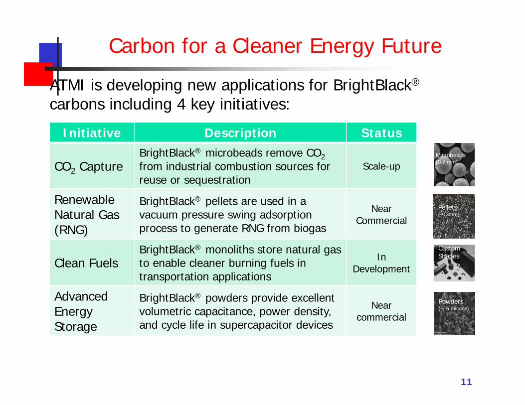
Carbon for a Cleaner Energy Future
11
ATMI is developing new applications for BrightBlack®
carbons including 4 key initiatives:
Initiative Description Status
CO2 CaptureBrightBlack® microbeads remove CO2from industrial combustion sources for reuse or sequestration
Scale-up
Renewable Natural Gas (RNG)
BrightBlack® pellets are used in a vacuum pressure swing adsorption process to generate RNG from biogas
Near Commercial
Clean FuelsBrightBlack® monoliths store natural gas to enable cleaner burning fuels in transportation applications
In Development
Advanced Energy Storage
BrightBlack® powders provide excellent volumetric capacitance, power density, and cycle life in supercapacitor devices
Nearcommercial
Microbeads(0.2 mm)
Pellets(~ 3mm)
Powders(~ 5 micons)
Custom Shapes
12
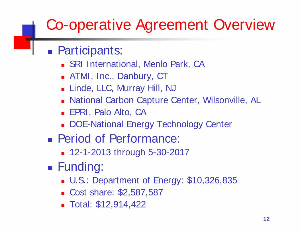
Co-operative Agreement Overview
Participants: SRI International, Menlo Park, CA ATMI, Inc., Danbury, CT Linde, LLC, Murray Hill, NJ National Carbon Capture Center, Wilsonville, AL EPRI, Palo Alto, CA DOE-National Energy Technology Center
Period of Performance: 12-1-2013 through 5-30-2017
Funding: U.S.: Department of Energy: $10,326,835 Cost share: $2,587,587 Total: $12,914,422
13
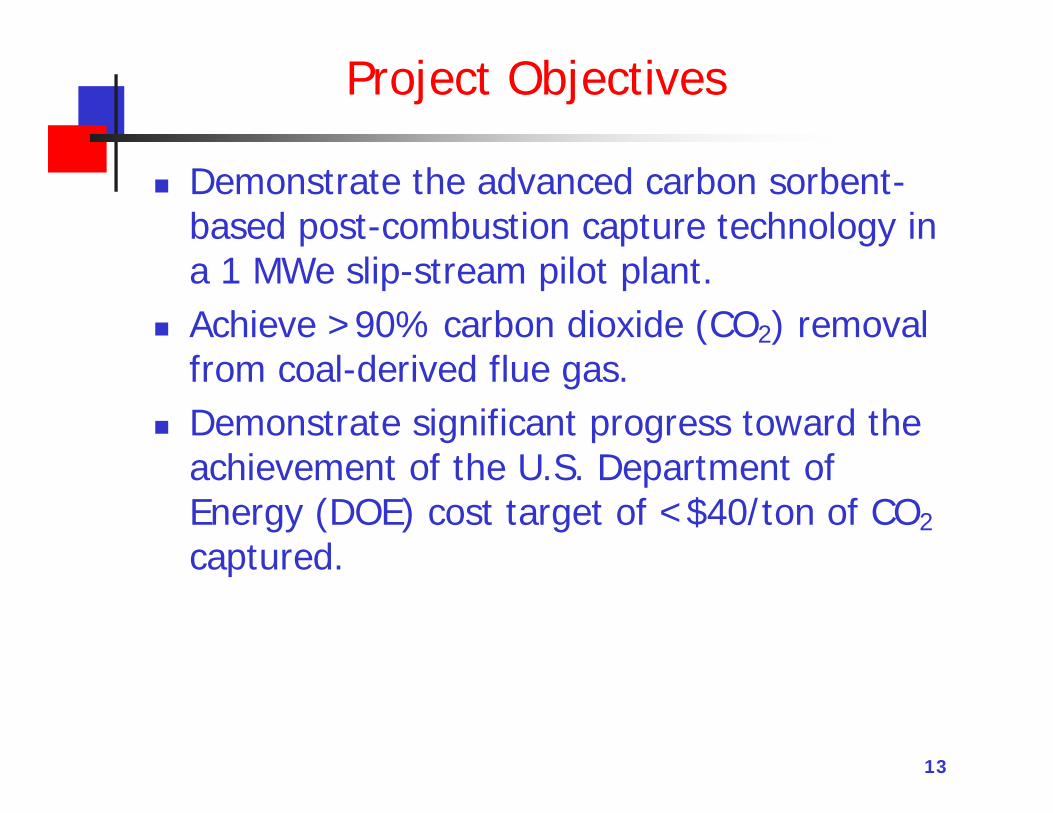
Project Objectives
Demonstrate the advanced carbon sorbent-based post-combustion capture technology in a 1 MWe slip-stream pilot plant.
Achieve >90% carbon dioxide (CO2) removal from coal-derived flue gas.
Demonstrate significant progress toward the achievement of the U.S. Department of Energy (DOE) cost target of <$40/ton of CO2
captured.
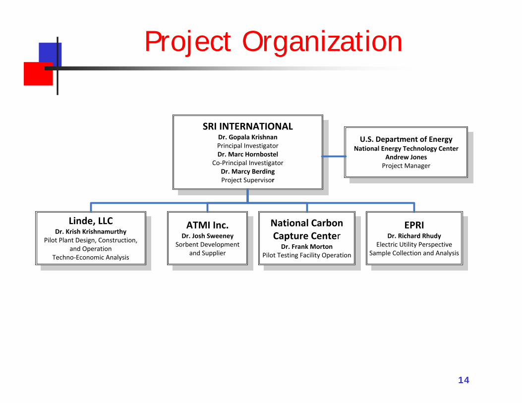
Project Organization
14
SRI INTERNATIONAL Dr. Gopala KrishnanPrincipal InvestigatorDr. Marc Hornbostel
Co-Principal InvestigatorDr. Marcy BerdingProject Supervisor
Linde, LLCDr. Krish Krishnamurthy
Pilot Plant Design, Construction, and Operation
Techno-Economic Analysis
ATMI Inc.Dr. Josh Sweeney
Sorbent Development and Supplier
National Carbon Capture Center
Dr. Frank MortonPilot Testing Facility Operation
EPRIDr. Richard Rhudy
Electric Utility PerspectiveSample Collection and Analysis
U.S. Department of EnergyNational Energy Technology Center
Andrew JonesProject Manager
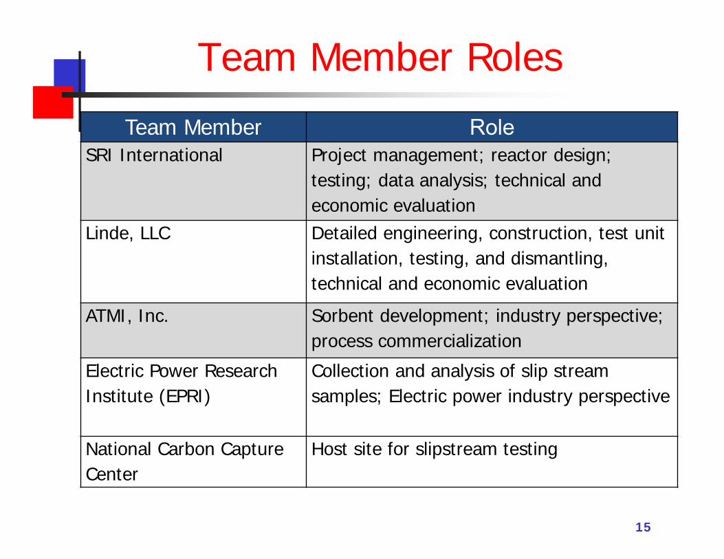
Team Member Roles
15
Team Member RoleSRI International Project management; reactor design;
testing; data analysis; technical and economic evaluation
Linde, LLC Detailed engineering, construction, test unit installation, testing, and dismantling, technical and economic evaluation
ATMI, Inc. Sorbent development; industry perspective; process commercialization
Electric Power Research Institute (EPRI)
Collection and analysis of slip stream samples; Electric power industry perspective
National Carbon Capture Center
Host site for slipstream testing
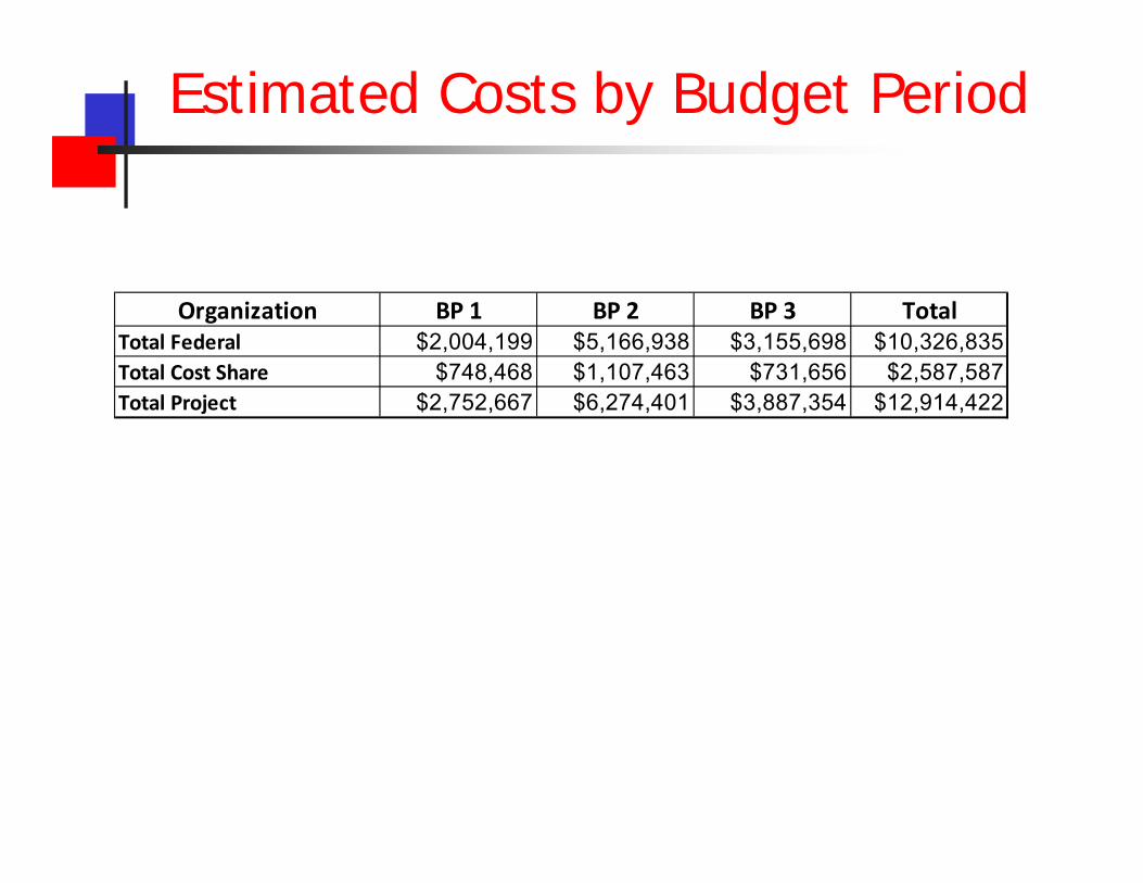
Estimated Costs by Budget Period
Organization BP 1 BP 2 BP 3 TotalTotal Federal $2,004,199 $5,166,938 $3,155,698 $10,326,835Total Cost Share $748,468 $1,107,463 $731,656 $2,587,587Total Project $2,752,667 $6,274,401 $3,887,354 $12,914,422
17
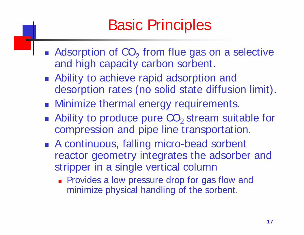
Basic Principles
Adsorption of CO2 from flue gas on a selective and high capacity carbon sorbent.
Ability to achieve rapid adsorption and desorption rates (no solid state diffusion limit).
Minimize thermal energy requirements. Ability to produce pure CO2 stream suitable for
compression and pipe line transportation. A continuous, falling micro-bead sorbent
reactor geometry integrates the adsorber and stripper in a single vertical column Provides a low pressure drop for gas flow and
minimize physical handling of the sorbent.
Sorbent – Chemical Properties
High CO2 capacity: The sorbent has a high capacity for CO2 adsorption
(20 wt% at 1 atm CO2) and good selectivity for CO2 over other flue gas components.
Rapid adsorption and desorption rates: The adsorption of CO2 occurs on the micropores of
the sorbent with very low activation energy (<5kJ/mole), allowing rapid cycling of the sorbent.
Low heat of adsorption and desorption: A relatively low heat of sorption (26 to 28 kJ/mole).
High hydrothermal stability: Direct heating with steam can be used for CO2
desorption.
19
Sorbent – Physical Properties
Mechanical robustness for long lifetime: Hard and attrition resistant; Unusually tough for a
high surface area (1600 m2/g) porous solid. ASTM Test D-5757: Attrition resistance very high. Field test for 7000 cycles – No noticeable attrition.
Spherical morphology of the sorbent granules:
Sorbent spheres (100 to 300 µm) allows a smooth flow.
This free-flowing, liquid-like characteristic allows the use of commercially available structural packing.
Low heat capacity: The low heat capacity of the sorbent (1 J/g/K)
and low density (1 g/cm3) minimizes the thermal energy needed to heat the sorbent to the regeneration temperature.
High thermal conductivity: The thermal conductivity of 0.8 W/m-K
enables rapid thermal equilibrium between the sorbent surface and interior.
2020
Summary of Previous Bench-Scale Tests
Developed an unique reactor system Integrated absorber-desorber geometry Minimize solids handling Minimize heat exchanger requirements.
Performed a 135 h test with a flue gas from a coal-fired boiler at the University of Toledo
The system was able to reduce the CO2 level from 4.5% to <0.05% (fully regenerated sorbent).
We achieved steady-state operation with 90% capture efficiency with >98% CO2 purity in the product gas.
Sorbent flow: Smooth!; Typical cycle time: ~1 min. No significant operational issues were observed (except for
cold-weather related problems – not process related).
Operation at University of Toledo
The system was operated during the day time from 8 AM to 7 PM, about 6 days a week for one month (including shake-down runs).
The flue gas flow rate was about 200 standard liters/min.
CO2 concentration: 4.5% v/v SO2 concentration: 60 ppm reduced to ~1 ppm
with the use of a FGD with sodium bicarbonate. NOx control was not practiced. Pressure drop across the adsorber: 0.4 inch WC. Total hours of operation: 130 hours (7,000 cycles)
21
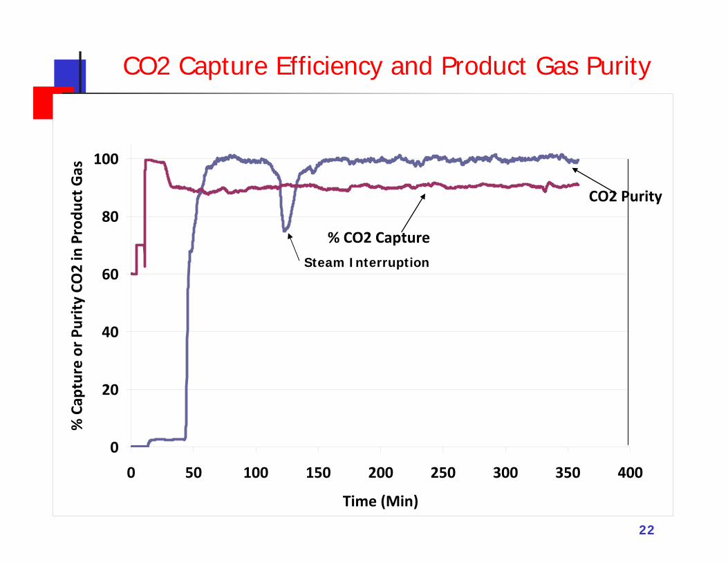
CO2 Capture Efficiency and Product Gas Purity
22
0
20
40
60
80
100
0 50 100 150 200 250 300 350 400
Time (Min)
% C
aptu
re o
r Pur
ity C
O2
in P
rodu
ct G
as
CO2 Purity
% CO2 Capture Steam Interruption
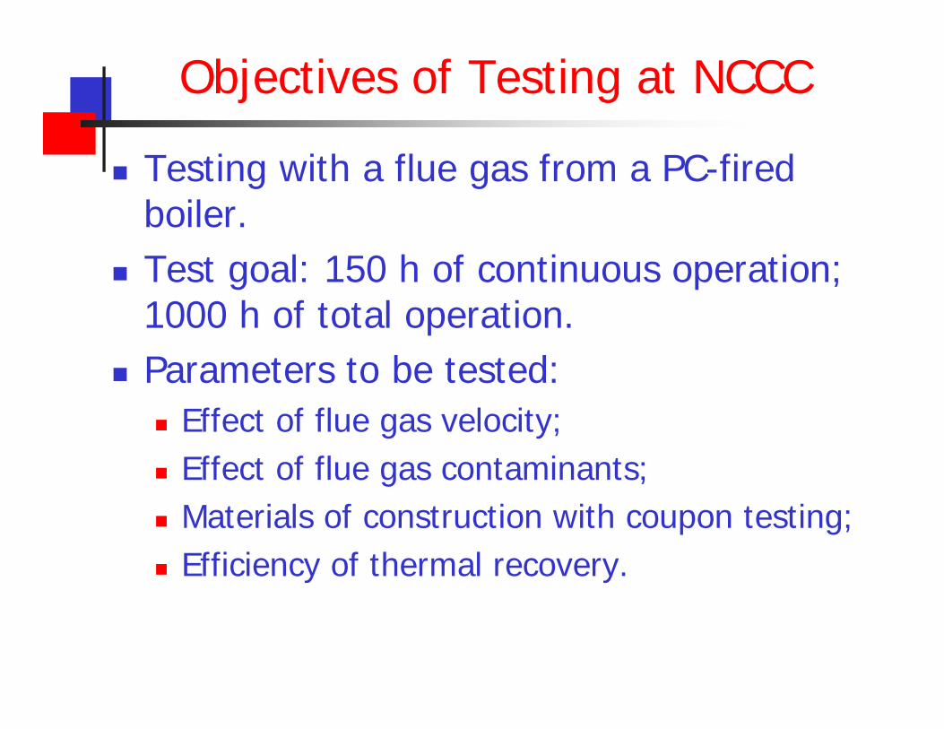
Objectives of Testing at NCCC
Testing with a flue gas from a PC-fired boiler.
Test goal: 150 h of continuous operation; 1000 h of total operation.
Parameters to be tested: Effect of flue gas velocity; Effect of flue gas contaminants; Materials of construction with coupon testing; Efficiency of thermal recovery.
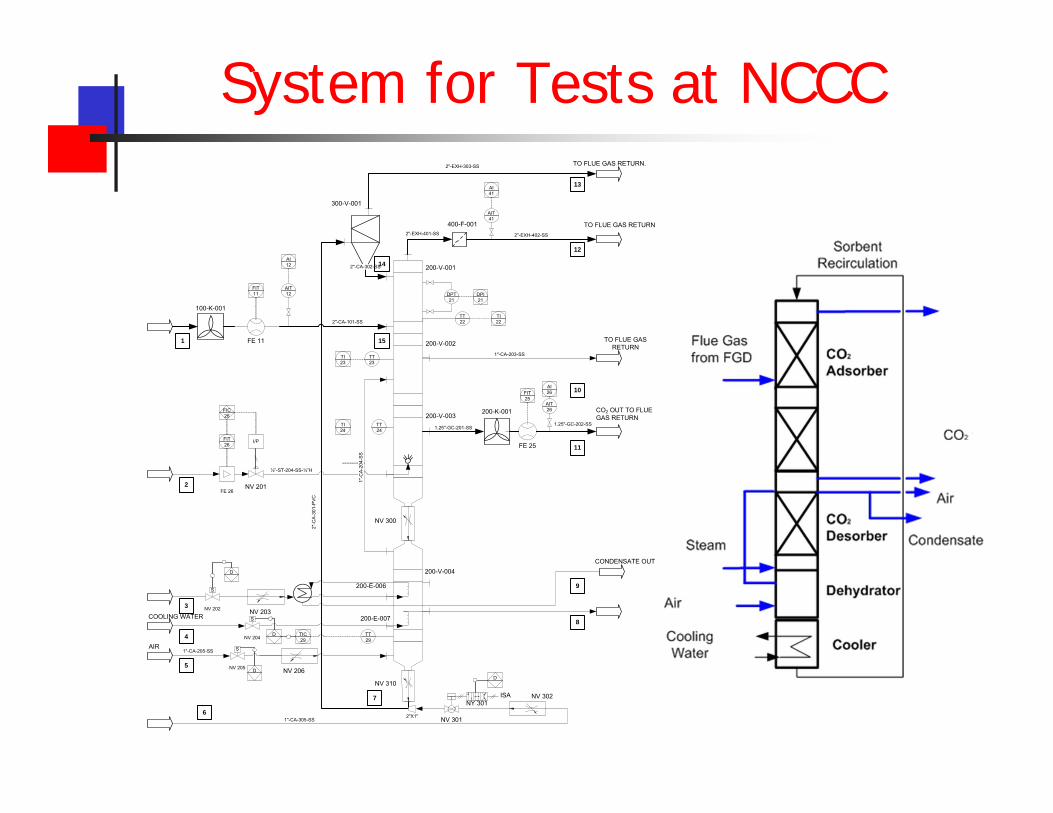
System for Tests at NCCC
200-V-001
200-V-002
200-V-003
200-V-004
300-V-001
2"-CA-302-SS
2"-C
A-3
01-P
VC
400-F-0012"-EXH-401-SS 2"-EXH-402-SS
TO FLUE GAS RETURN
AIT41
AI41
DPT21
DPI21
TT22
TI22
200-K-001
1.25"-GC-201-SS1.25"-GC-202-SS
CO2 OUT TO FLUE GAS RETURN
FE 25
FIT25
AIT26
AI26
1"-CA-203-SS
TO FLUE GAS RETURN
200-E-007
2"-EXH-303-SS TO FLUE GAS RETURN.
1"-CA-305-SS NV 301
NY 301
2"X1"
COOLING WATER
D
TT29
TIC29
S
NV 204D
ISA
200-E-006
CONDENSATE OUT
NV 201
FIT26
FIC26
FE 26
I/P
½”-ST-204-SS-½”H
TT23
TI23
TT24
TI24
AIR1"-CA-205-SS
1"-C
A-20
4-SS
S
NV 205 D
100-K-001
FE 11
FIT11
AIT12
AI12
2"-CA-101-SS
NV 302
NV 206
S
NV 202
D
NV 203
1
2
3
4
5
6
7
8
9
10
11
12
13
14
15
NV 300
NV 310
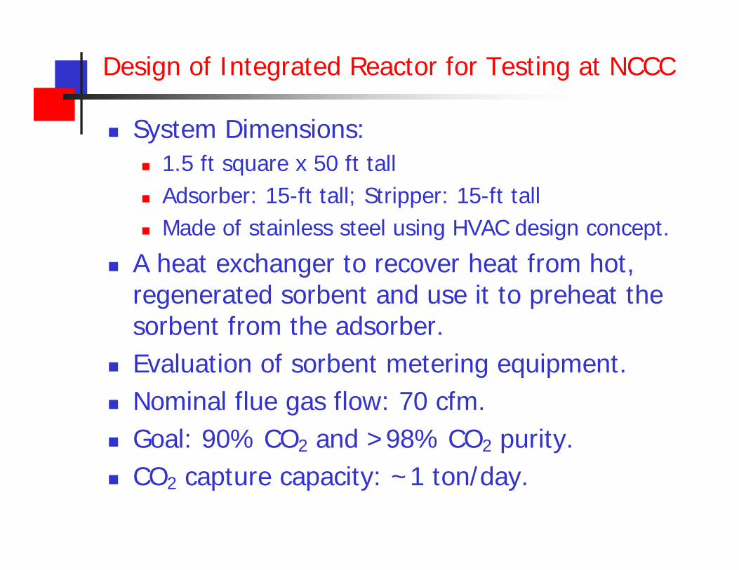
Design of Integrated Reactor for Testing at NCCC
System Dimensions: 1.5 ft square x 50 ft tall Adsorber: 15-ft tall; Stripper: 15-ft tall Made of stainless steel using HVAC design concept.
A heat exchanger to recover heat from hot, regenerated sorbent and use it to preheat the sorbent from the adsorber.
Evaluation of sorbent metering equipment. Nominal flue gas flow: 70 cfm. Goal: 90% CO2 and >98% CO2 purity. CO2 capture capacity: ~1 ton/day.
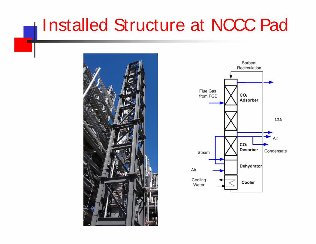
Installed Structure at NCCC Pad
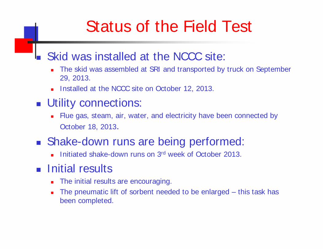
Status of the Field Test
Skid was installed at the NCCC site: The skid was assembled at SRI and transported by truck on September
29, 2013. Installed at the NCCC site on October 12, 2013.
Utility connections: Flue gas, steam, air, water, and electricity have been connected by
October 18, 2013.
Shake-down runs are being performed: Initiated shake-down runs on 3rd week of October 2013.
Initial results The initial results are encouraging. The pneumatic lift of sorbent needed to be enlarged – this task has
been completed.
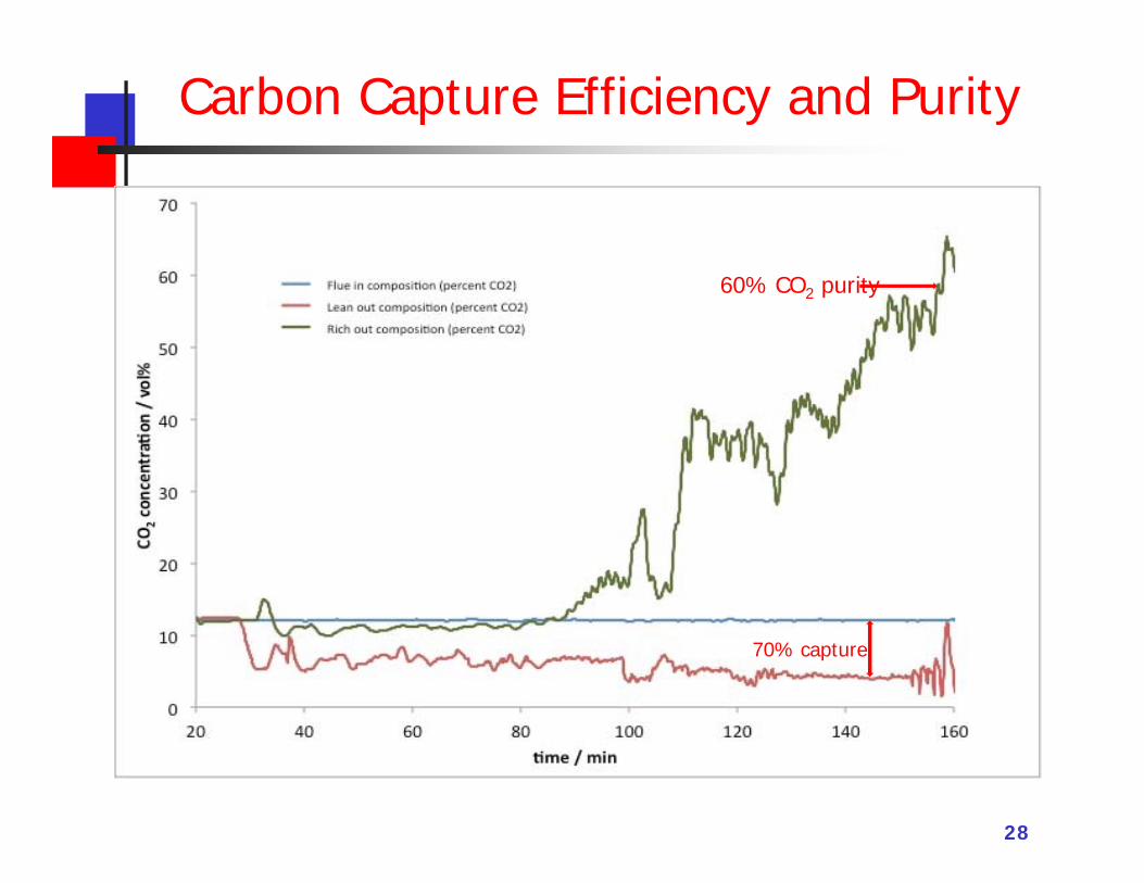
Carbon Capture Efficiency and Purity
28
70% capture
60% CO2 purity
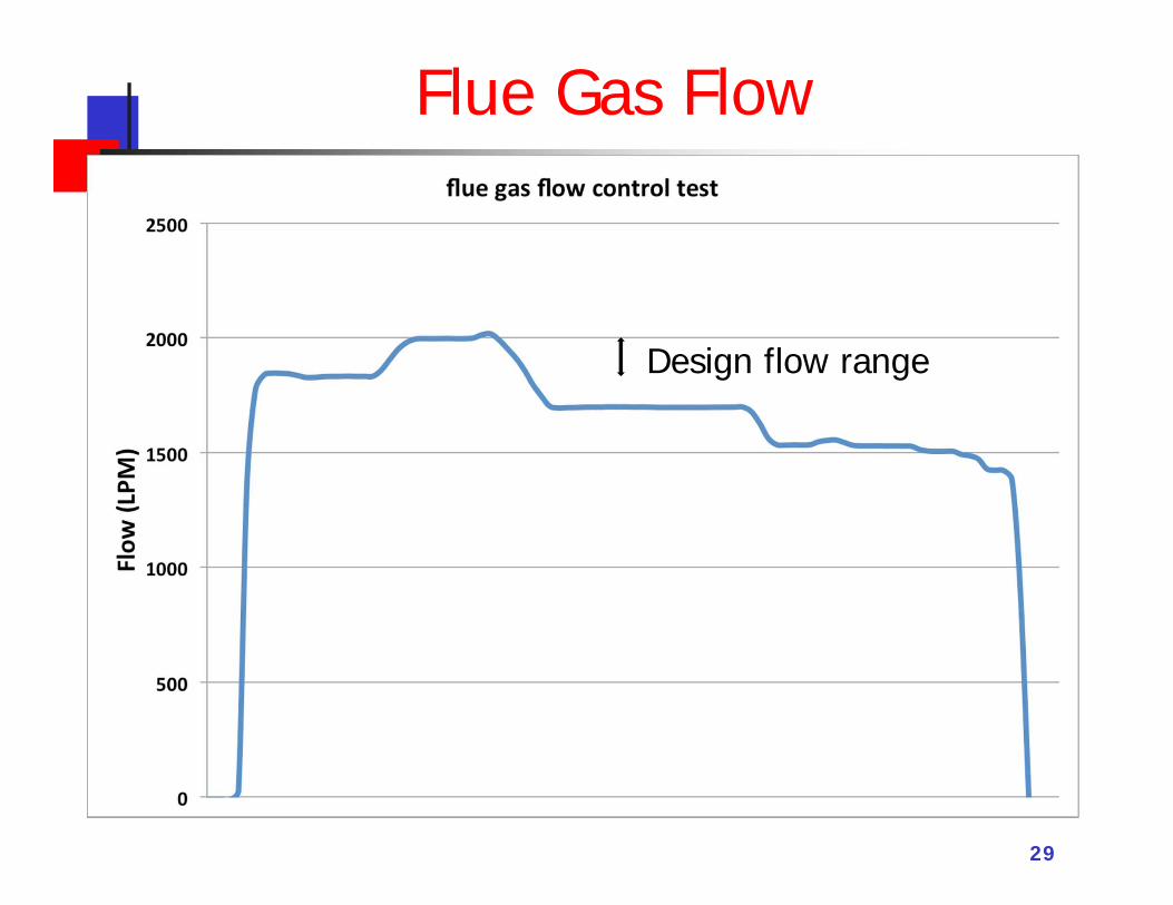
Flue Gas Flow
29
Design flow range
30
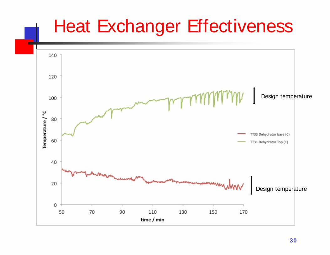
Design temperature
Design temperature
Heat Exchanger Effectiveness
3131
Budget Periods
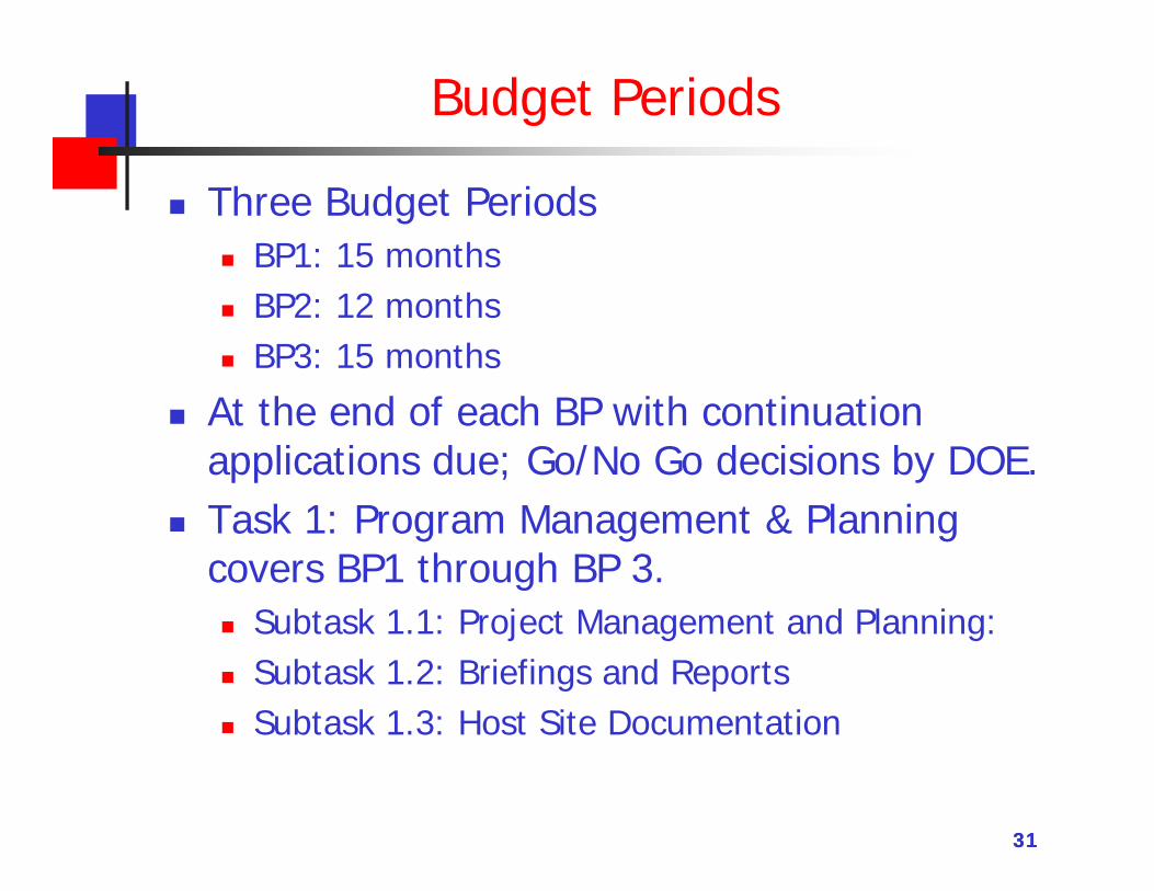
Three Budget Periods BP1: 15 months BP2: 12 months BP3: 15 months
At the end of each BP with continuation applications due; Go/No Go decisions by DOE.
Task 1: Program Management & Planning covers BP1 through BP 3. Subtask 1.1: Project Management and Planning: Subtask 1.2: Briefings and Reports Subtask 1.3: Host Site Documentation
32
Budget Period 1 Activities
Task 2.0: Sorbent Testing at National Carbon Capture Center (SRI Lead) Complete the field test of the sorbent testing
Task 3.0: Initial Techno-Economic Analysis (SRI Lead) Complete an initial TEA of a 550 MWe power plant incorporating the
carbon sorbent based post-combustion CO2 capture technology to illustrate the benefits of the process.
Conduct an initial EH&S risk assessment of the process.
GO/NO GO DECISION POINT
Task 4.0: Sorbent Specification (ATMI Lead) Specify sorbent formulations for pilot-scale testing including properties
related to performance, stability and cost;
Review manufacturing options for sorbent production and supply for large-scale applications.
Budget Period 1 Activities Task 5.0: 1 MWe Pilot Plant Design (Linde Lead)
Develop the plant concept and operating cases using available data relating to: On-site conditions, process design conditions, feedstock, products, utilities, noise,
measurement units, required codes and standards, and the specification of effluents and waste streams in order to finalize the design basis document.
Develop Basic Engineering Design Package: Design basis; Process design;
Equipment list; Equipment data sheets;
Piping and instrumentation;
Electrical line diagrams, control data sheets, logic diagrams and alarms and interlocks;
Safety requirements;
General design documents including specification of materials, test and inspection procedures, and applicable standards.
33
Budget Period 1 Activities Task 6.0: Pilot Plant Safety Analysis (Linde Lead) A comprehensive design and internal Process Safety Review
(PSR), and a HazOP study Subtask 6.1: HazOp Study Subtask 6.2: Transportation and Lifting Study Subtask 6.3: Initial EH&S Risk Assessment
Task 7.0: Pilot Plant Detailed Engineering and Cost Assessment (Linde Lead) Subtask 7.1: Detailed Design and Engineering
Final pilot plant design will include all the required mechanical details of the system, including updated equipment specifications, layout, and piping isometrics.
Subtask 7.2: Development of Equipment Package Define the scope for the purchase of plant components and materials for
piping, electrical, and instrumentation. Subtask 7.3: Pilot Plant Cost Estimation
Based on equipment and system fabrication bids received from vendors in response to the bid packages
Decision Point – Go/No Go34
Budget Period 2 Activities Task 8.0: Pilot Plant Equipment Procurement and Fabrication
Complete the final equipment and module vendor packages for system fabrication at a fabrication shop.
Review and finalize all specifications, terms and conditions, schedule, and installation contracts.
Review with the fabricator and host site for shipping arrangements from the fabrication shop to the host site.
Monitored and review to ensure that the equipment and modules are fabricated, as per specification and in a timely manner.
Task 9.0: Civil and Structural Engineering Work with a general contractor, acceptable to the host site, to specify
the civil structure design, including foundations. Complete the designs for the electrical, piping, and instrumentation
conduits for the pilot plant, and the connections from the supply and utility lines to the pilot plant.
35
Budget Period 2 Activities Task 10.0: Pilot Plant Installation
Coordinate with the host site on receiving, lifting, and installation of the equipment into position.
Review all tie-ins from the host-site coal power plant flue gas and utilities, such as steam, cooling water, electricity, and return lines for CO2 depleted gas.
Ensure that all the interconnecting lines, electrical wiring, and control devices are properly installed.
Task 11: Sorbent Production for Pilot Testing ~1 metric ton of each material will be produced. Sorbent material
will be produced in existing pilot furnaces Two different batches of material, based on the specifications
generated in Task 3.
Decision Point – Go/No Go
36
Budget Period 3 Activities Task 12.0: Operation of the Pilot Plant
Field testing of the 1 MWe pilot plant at the host site, including commissioning, the parametric test campaign, and the long-duration test.
Subtask 12.1: Pilot Plant Commissioning Shake-down runs to ensure that all the interconnecting lines,
electrical wiring, and control devices are properly functioning. Testing of utility systems; safety systems; operation and automation
functions; and functional testing of critical sub-systems. check all the sampling and analysis points to ensure that the
sampling is properly set-up and the analyzers are functional and calibrated.
Subtask 12.2: Development of a Test Plan In close consultation with DOE’s project manager develop a test
plan to obtain experimental data under parametric and steady-state conditions using industrially-relevant conditions that can be used reliably for updating the TEA.
37
Budget Period 3 Activities Subtask 12.3: Parametric Testing
Determine the effect of various operating parameters on the efficiency of CO2 capture from the flue gas and the purity of the product CO2 stream.
Collect samples will be taken over the selected test duration to establish changes in the sorbent characteristics
Identify the optimum operating conditions that maximize process performance for the selected sorbent
Subtask 12.4: Long Duration Testing Operate the pilot plant under continuous, steady-state conditions for
at least three (3) months. Validate sorbent stability, attrition measurements, and other
parameters affecting long-term performance. Collect and analyze samples from input and output gas, solid, and
liquid streams for various constituents that are relevant to the power utility and chemical industries.
38
Budget Period 3 Activities Task 13.0: Final Technology Assessment Subtask 13.1: Updated TEA
Update the TEA of the advanced carbon sorbent-based process based on the results of the 1 MWe pilot-scale test program
In accordance with the guidelines provided in SOPO
Subtask 13.2: Updated EH&S Risk Assessment Update the E&HS Risk assessment of the advanced carbon sorbent-
based process based on the results of the 1 MWe pilot-scale test program
In accordance with the guidelines provided in SOPO
Subtask 13.3: Commercialization Plan Linde will take the lead on the commercialization plan in close
cooperation with other critical parties in the team. Explore attractive opportunities for a future demonstration at the 10
to 25 MWe scale.
39
Budget Period 3 Activities Task 14.0: Pilot Plant Decommissioning
dismantling the pilot plant at the host site location. They will also be accountable for removal of the pilot plant equipment either to storage, or to the appropriate disposal facility
Proper disposal of the spent and unused sorbent material in an agreement with host site.
40
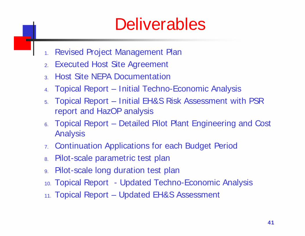
Deliverables1. Revised Project Management Plan2. Executed Host Site Agreement3. Host Site NEPA Documentation 4. Topical Report – Initial Techno-Economic Analysis5. Topical Report – Initial EH&S Risk Assessment with PSR
report and HazOP analysis6. Topical Report – Detailed Pilot Plant Engineering and Cost
Analysis7. Continuation Applications for each Budget Period8. Pilot-scale parametric test plan9. Pilot-scale long duration test plan10. Topical Report - Updated Techno-Economic Analysis11. Topical Report – Updated EH&S Assessment
41