Embed Size (px)
Citation preview
ELECTRONICALLY REPRINTED FROM AUGUST 2018 www.bcadigital.com
Business & Commercial Aviation
OF EDITORIALEXCELLENCE
PILOT REPORT
Pilatus PC-24
Pilatus PC-24A business jet in a class all its ownBY FRED GEORGE [email protected]
Pilot Report
The much-anticipated Pilatus PC-24 might well be named the big Swiss surprise. Many people confuse it for a tur-bofan-powered variant of the PC-12. That would put it in the light jet class of the Cessna Citation CJ4 or Embraer
Phenom 300, a market segment already overcrowded.
But it’s actually a midsize jet with a slightly larger cross-section than a Cita-tion XLS+. Admittedly, it has 7 in. less headroom in the center of the cabin; however, that’s because it has a con-tinuous flat floor rather than an 8-in. dropped aisle. The main seating area is 2.7 ft. longer than in the XLS+, affording comfortable seating for six people in the standard executive interior. With 500 cu. ft. of cabin volume, interior size alone puts the PC-24 into a midsize jet class that’s sparsely populated, now that the Gulfstream G150, Hawker 900XP and most of the midsize Citations no longer are in production.
“We wanted a small widebody,” says Chairman Oscar Schwenk. “In the begin-ning, it was even wider. But that caused too much drag. We think we have a good compromise now.”
The PC-24, similar to the PC-12, has several exclusive qualities that arguably move it into a class of its own. The sig-nature feature is its 17-sq.-ft. aft cargo door that swings up to provide access to a 90-cu.-ft. aft, pressurized cargo com-partment. Incorporating the large door into the aircraft design was no mean feat, considering the aircraft’s 8.8-psi pressurization system and strict empty weight budget. The proximity of the wing trailing edge and rear-mounted engine air inlets to the cargo door posed further challenges to Pilatus engineers.
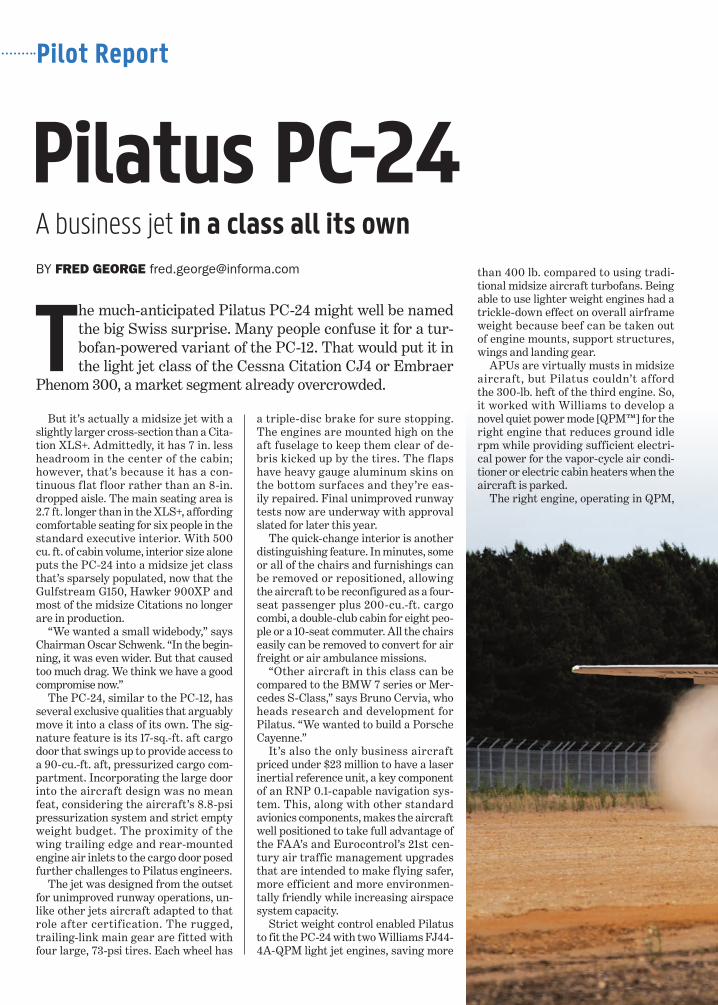
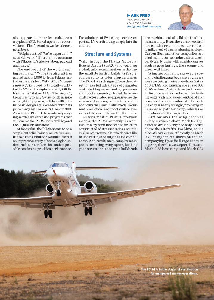
The jet was designed from the outset for unimproved runway operations, un-like other jets aircraft adapted to that role after certification. The rugged, trailing-link main gear are fitted with four large, 73-psi tires. Each wheel has
a triple-disc brake for sure stopping. The engines are mounted high on the aft fuselage to keep them clear of de-bris kicked up by the tires. The flaps have heavy gauge aluminum skins on the bottom surfaces and they’re eas-ily repaired. Final unimproved runway tests now are underway with approval slated for later this year.
The quick-change interior is another distinguishing feature. In minutes, some or all of the chairs and furnishings can be removed or repositioned, allowing the aircraft to be reconfigured as a four-seat passenger plus 200-cu.-ft. cargo combi, a double-club cabin for eight peo-ple or a 10-seat commuter. All the chairs easily can be removed to convert for air freight or air ambulance missions.
“Other aircraft in this class can be compared to the BMW 7 series or Mer-cedes S-Class,” says Bruno Cervia, who heads research and development for Pilatus. “We wanted to build a Porsche Cayenne.”
It’s also the only business aircraft priced under $23 million to have a laser inertial reference unit, a key component of an RNP 0.1-capable navigation sys-tem. This, along with other standard avionics components, makes the aircraft well positioned to take full advantage of the FAA’s and Eurocontrol’s 21st cen-tury air traffic management upgrades that are intended to make flying safer, more efficient and more environmen-tally friendly while increasing airspace system capacity.
Strict weight control enabled Pilatus to fit the PC-24 with two Williams FJ44-4A-QPM light jet engines, saving more
than 400 lb. compared to using tradi-tional midsize aircraft turbofans. Being able to use lighter weight engines had a trickle-down effect on overall airframe weight because beef can be taken out of engine mounts, support structures, wings and landing gear.
APUs are virtually musts in midsize aircraft, but Pilatus couldn’t afford the 300-lb. heft of the third engine. So, it worked with Williams to develop a novel quiet power mode [QPM™] for the right engine that reduces ground idle rpm while providing sufficient electri-cal power for the vapor-cycle air condi-tioner or electric cabin heaters when the aircraft is parked.
The right engine, operating in QPM,
ASK FRED Send your questions about this article to: [email protected]
also appears to make less noise than a typical APU, based upon our obser-vations. That’s good news for airport neighbors.
“Weight control? We’re expert at it,” says Schwenk. “It’s a continuous game with Pilatus. It’s always about payload and range.”
The end result of the weight sav-ing campaign? While the aircraft has gained nearly 1,000 lb. from Pilatus’ ini-tial estimates for BCA’s 2018 Purchase Planning Handbook, a typically outfit-ted PC-24 still weighs about 1,000 lb. less than a Citation XLS+. The aircraft, though, is typically Swiss tough in spite of its light empty weight. It has a 30,000-hr. basic design life, exceeded only in its price range by Embraer’s Phenom 300. As with the PC-12, Pilatus already is ey-ing service life extension programs that will enable the PC-24 to fly well beyond the 30,000-hr. milestone.
At face value, the PC-24 seems to be a simple but solid Swiss product. Yet, sim-ilar to a Patek Phillippe Nautilus, there’s an impressive array of technologies un-derneath the surface that makes pos-sible consistent, precision performance.
For admirers of Swiss engineering ex-pertise, it’s worth diving deeply into the details.
Structure and SystemsWalk through the Pilatus factory at Buochs Airport (LSZC) and you’ll see a wholesale transformation in the way the small Swiss firm builds its first jet compared to its older prop airplanes. The PC-24 was designed from the out-set to take full advantage of computer controlled, high-speed milling processes and robotic assembly. Skilled Swiss air-craft factory labor is expensive, so the new model is being built with fewer la-bor hours than any Pilatus model in cur-rent production. And robots will do even more of the assembly work in the future.
As with most of Pilatus’ previous models, the PC-24 primarily is an alu-minum alloy, semi-monocoque structure constructed of stressed skins and inte-gral substructure. Cervia doesn’t like to use castings or forgings for compo-nents. As a result, most complex metal parts including wing spars, landing gear struts and nose gear bulkheads
are machined out of solid billets of alu-minum alloy. Even the cursor control device palm grip in the center console is milled out of a solid aluminum block. Carbon fiber and other composites are used mainly for secondary structures, particularly those with complex curves such as aero fairings, the radome and wheel well liners.
Wing aerodynamics proved espe-cially challenging because engineers were targeting cruise speeds as fast as 440 KTAS and landing speeds of 100 KIAS or less. Pilatus developed its own airfoil, one with a cranked-arrow lead-ing edge with mild sweep outboard and considerable sweep inboard. The trail-ing edge is nearly straight, providing an unimpeded path for cargo vehicles or ambulances to the cargo door.
Airf low over the wing becomes mildly transonic above Mach 0.7. Sig-nificant drag divergence only occurs above the aircraft’s 0.74 Mmo, so the aircraft can cruise efficiently at Mach 0.72 or higher. As shown on the ac-companying Specific Range chart on page 36, there’s a 7.5% spread between Mach 0.65 best range and Mach 0.74
The PC-24 is in the stages of certification for unimproved runway operations.
Pilot Report
compartment. Battery 2 is in a com-partment aft of the right wing. During normal operation with both engines run-ning, Battery 1 is connected to the left generator and main bus while Battery 2 is tied to the right generator and main bus. Bus tie relays connect normally split buses together when connected to ground power or with only one genera-tor operating.
The 6,000-lb. capacity fuel system has mirror-image left and right wet-wing tanks. Each tank may be refueled through an over-wing port. A single-point pressure refueling port ahead of the right wing allows both wings to be refilled to a quantity programmed into an external control panel or fuel synop-tic page on the MFD.
When the engines are running, main and transfer jet pumps move fuel to the engines. DC boost pumps, with motors in dry cannisters for quick removal and replacement, provide fuel pressure for engine starting, cross-feed, cross-flow and defueling, as well as backing up the jet pumps. An automatic fuel bal-ance system keeps left- and right-side quantities within 200 lb. A warm fuel recirculation system maintains an even temperature throughout the wing tanks.
The primary f light controls are manually actuated. Cockpit controls are connected to the ailerons, elevator and rudder by means of conventional chains, sprockets, cables, sector wheels and push-pull rods. Balance tabs reduce control force. The rudder and left aile-ron tab double as trim tabs. Pitch trim is provided by the trimmable horizontal stabilizer. A rudder travel limiter re-duces movement of the surface based upon flap position to prevent rudder lock. A rudder bias function is incor-porated into the yaw damper to reduce pedal effort by up to 50 lb. due to thrust asymmetry during engine failure.
As with the PC-12, a pre-stall stick shaker and stick pusher provide high angle of attack protection. At high speed, a Mach trim system adjusts the horizontal stabilizer position to compen-sate for Mach tuck above the aircraft’s 0.74 Mmo. The airbrakes also begin to extend automatically above Mach 0.751 to help prevent the aircraft from accel-erating much past Mmo.
All the secondary flight controls are electrically actuated, including the trim-mable horizontal stabilizer, trim tabs, ground spoilers, multifunction spoil-ers and wing flaps. The spoilers extend symmetrically in flight to function as two-position air brakes, 20 deg. up at the
the anti-skid wheel brakes, probe and windshield heat. Fuel boost pumps and the pressurization system use electric power. Electric brakes may be used on future aircraft if the price becomes more attractive.
The PC-24 is the first production business aircraft to use brushless AC induction starter/generators. Astronics Corp. attempted to perfect the system 15 years ago with the intention of introduc-ing it on the Eclipse 500, but the tech-nology wasn’t ready. Now, it’s making its debut on the Pilatus jet. Each engine has a compact, lightweight, three-phase alternator that generates unregulated, wild-frequency AC power. A power conversion unit (PCU) transforms the AC into regulated 28-volt DC/400-amp power.
The AC starter/generators produce considerably more power at low rpm
than conventional DC starter/genera-tors. Thus, up to 250 amps of power are available from the FJ44-4A-QPM in the 45.4% reduced idle speed QPM, at least 8% lower than normal idle. Cervia says air-condition peak demand for rapid cooling requires only 220 amps, leaving 30 amps surplus for other electrical sys-tems. Prior to engine start, the aircraft also may be connected to ground power for cabin cooling or heating.
In the start mode, the PCUs convert 16- to 29-volt DC power from the aft battery, the cross-side generator or a ground power unit into high-voltage, high-frequency AC power to energize the starters.
Similar to PC-12NG, the PC-24 has a forward systems Battery 1 and an aft start Battery 2. Each 24-volt, 44-amp/hour NiCad battery is easily accessible. Battery 1 is on a shelf in the left nose
best speed cruise profiles.The wing is built in left and right
halves with forward and aft single-piece, machined spars, plus a short sub-spar for the aft attach point of the main landing gear. It’s a conventional ladder box design using chordwise ribs and shot-peen formed skins attached with mechanical fasteners to the interior sub-structure. Left and right halves are at-tached in the center by several tension bolts to form a single piece. The wing attaches to the fuselage pairs of forward and aft fittings, plus a forward spigot and socket fitting to locate the wing on the fuselage centerline.
The fuselage has forward, pressure vessel, tail and empennage sections. Pila-tus worked with the Swiss firm Mecaplex to develop new generation, lighter weight, glass-faced acrylic transparencies for the windshields and cockpit side windows.
The main cabin has 13 stretched acrylic windows. The left side has one less win-dow than the right to make room for the 4.4-ft.-high-by-2.1-ft.-wide airstair entry door. Each side of the fuselage has a Type IV plug-design overwing emergency exit. The aft 4.3-ft.-high-by-4.1-ft.-wide cargo door only can be opened or closed from outside the aircraft, thus it cannot qualify as an emergency exit. Counter springs as-sist closing the main door and opening the cargo door. An electric winch motor closes the cargo door. Both main and cargo doors are secured with mechanically actuated bayonet-design shoot bolts.
Cervia designed the aircraft to have virtually all electric power systems. Electrical power is used for avionics, lights and cargo door closing, plus land-ing gear, f lap and spoiler actuation, along with air conditioning and cabin heating, the hydraulic power pack for
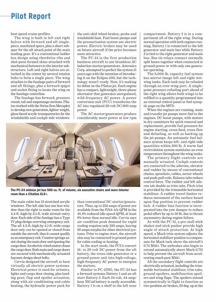
The PC-24 midsize jet has 500 cu. ft. of volume, six executive chairs and more interior room than a Citation XLS+.
condition. The internal cargo compart-ment is fitted with a smoke detector that triggers a CAS alert.
Most business aircraft use a federa-tion of a dozen or more computers to control and monitor all those systems. But the PC-24 is a truly integrated platform that has a Utility Manage-ment System (UMS), furnished by Innovative Solutions & Systems in Exton, Pennsylvania. The UMS inte-grates virtually all systems aboard the aircraft except for the engine FADECs, digital flight control system and avionics. UMS-24, as IS&S calls the system aboard the PC-24, features open architecture, so it will accommo-date systems made by a wide variety of manufacturers. It will handle up to seven dual-channel data concentration and processing units (DCPUs), but only four are needed aboard the Pilatus jet to handle more than 40 functions.
Each DCPU has dual data channels, Ethernet and RS422 that use dissimi-lar hardware and software to mini-mize the risk of common cause failure of both systems. Essential functions are assigned two or three channels, sometimes in different DCPUs, to provide redundancy. Crew control of UMS functions is provided by discrete switches, levers, knobs and buttons, plus softkey controls. The UMS pro-vides indications through the EICAS. The UMS is context sensitive, so it au-tomatically calls up the appropriate sys-tem synoptic on the MFD based upon checklist item or abnormal situation.
Passenger Comfort and Convenience
Pilatus seemingly has taken a lesson from Dassault regarding illusive pack-aging since the PC-24’s modest exterior proportions belie its relatively large cabin dimensions. Its footprint is about the same as that of the Citation XLS+, but it offers about 19% more interior volume.
Primary access is provided by the forward airstair cabin door. It has a spring-loaded counterbalance to offset its heft, a sturdy forward side handrail and left and right telescoping door sup-ports that are immune from tangling woes that can snare support chains or cables, especially if the wind is blowing on the ramp. Just inside the aft side of the door frame, there’s a push-button switch linked to the hot battery bus that powers up entrance lights, including
pedals provide 16 deg. ± 1 deg. positive steering authority, but the nosewheel also will free caster up to 60 deg. for tight turns. When retracted, the nose gear is fully enclosed by three doors. Outboard doors partially enclose the main gear, leaving the outboard wheels exposed. Wheel covers and brush seals in the wheel wells minimize drag. A guarded emergency landing-gear ex-tension lever in the cockpit releases all three landing gear uplocks, allow-ing them to free-fall into the down and locked positions.
Fire/overheat sensors are fitted to each engine nacelle area. Fore and aft extinguisher bottles, each contain-ing Halon 1301, can be individually discharged to either or both engines. Overheat detectors in the bleed air system trigger crew alerting system (CAS) alerts. Various components can be isolated to eliminate the overheat
one-half position and 35 deg. up at full out. They may be fully deployed above 50 ft. AGL with flaps extended to pro-vide high drag for steep approaches.
The multifunction spoilers also ex-tend asymmetrically, in proportion to upward aileron movement when the flaps are extended, to augment roll con-trol authority.
Curtiss-Wright supplies the com-pact, but powerful, planetary geared flap actuators and “power hinge” rotary airbrake and multifunction spoiler ac-tuators. Unequal length arms and scis-sors links, fully enclosed in fairings in the clean wing configuration, control the movement of the double slotted Fowler flaps. Cervia insisted on eliminating flap tracks that could be prone to jamming due to dirt and debris accumulation.
The interior features two-zone, cock-pit and cabin temperature control. Air Comm Corp. in Boulder, Colorado, fur-nishes the 19-lb., electrically powered, 27,000-BTU vapor-cycle air conditioner, cockpit and cabin air distribution sys-tems, and five thermally self-regulating ceramic heaters for the cabin. When the engines are running, bleed air heating is available.
Temperature-controlled bleed air provides 8.8-psi pressurization, which is sufficient to maintain an 8,000-ft. cabin altitude at FL 450. Using departure field ambient pressure, takeoff and landing field elevations, the FMS automatically schedules pressurization for each flight.
Bleed air also is used for engine in-let and wing leading edge anti-ice pro-tection, along with horizontal stabilizer lead edge deice boot operation. The windshields, Rosemount pitot-static probes and angle-of-attack vanes are electrically heated for anti-ice protec-tion. Dual ice detectors enable auto-matic activation of the ice protection system when needed.
The landing gear are f itted with electromechanical actuators that are electrically heated to assure proper operation in extremely cold weather. The long travel, trailing link main gear and dual mains are well-suited to unim-proved runway operations. A 3,000-psi electric/hydraulic power pack supplies the triple steel disc, anti-skid power brakes. Owing to the aircraft’s rela-tively low V speeds, there is no need for a brake temperature monitoring system.
Mechanical linkages to the rudder
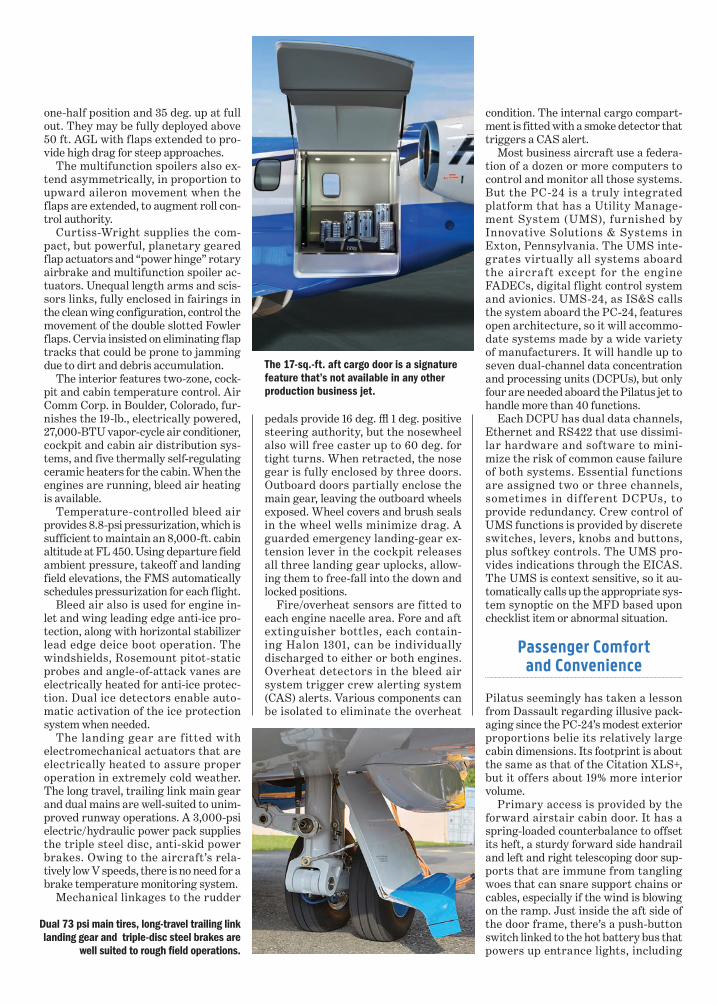
Dual 73 psi main tires, long-travel trailing link landing gear and triple-disc steel brakes are
well suited to rough field operations.
The 17-sq.-ft. aft cargo door is a signature feature that’s not available in any other production business jet.
Pilot Report
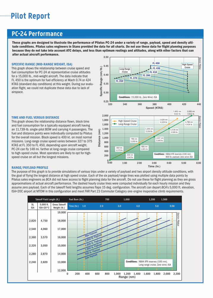
TIME AND FUEL VERSUS DISTANCE This graph shows the relationship distance flown, block time and fuel consumption for a typically equipped aircraft having an 11,739-lb. single-pilot BOW and carrying 4 passengers. The fuel and distance points were individually computed by Pilatus for the overall mission. Block speed is 400 kt. on most normal missions. Long-range cruise speed varies between 327 to 375 KTAS at FL 350 to FL 450, depending upon aircraft weight. PC-24 can fly 148 mi. farther at long-range cruise compared to high-speed cruise. Most operators are likely to opt for high- speed cruise on all but the longest missions.
PC-24 PerformanceThese graphs are designed to illustrate the performance of Pilatus PC-24 under a variety of range, payload, speed and density alti-tude conditions. Pilatus sales engineers in Stans provided the data for all charts. Do not use these data for flight planning purposes because they do not take into account ATC delays, and less than optimum routings and altitudes, along with other factors that can alter actual aircraft performance.
0.25
0.30
0.35
0.40
0.45
0.50
320 340 360 380 400 420 440Spe
ci�c
Ran
ge (
nm/l
b.)
Speed (KTAS)
Source: Pilatus
Conditions: 15,000 lb., Zero Wind, ISA
High-SpeedCruise
Long-RangeCruise
FL 350FL 370
FL 390FL 410
FL 430
FL 450
0
200
400
600
800
1,000
1,200
1,400
1,600
1,800
2,000
0:00 1:00 2:00 3:00 4:00 5:00 6:00
Dis
tanc
e (n
m)
Time (hr.)
Source: Pilatus
364 nm1,173 lb.
High-Speed CruiseLong-Range Cruise
Conditions: NBAA IFR reserves (100 nm)800 lb. payload, Zero wind, ISA
330 nm1,047lb.
685 nm1,821 lb.
785 nm2,200 lb.
1,047 nm2,640 lb.
1,206 nm3,250 lb.
1,418 nm3,509 lb.
1,626 nm4,329 lb.
1,852 nm4,922 lb.
2,000 nm4,922 lb.
1,798 nm4,434 lb.
13,000
12,000
14,000
15,000
16,000
17,000
18,000
2,870
3,050
4,060
4,750
2,280
2,8202,240
2,320
2,540
3,5702,360
2,820
19,000
4000 800 1,200 1,600 2,000200 600 1,000 1,400 1,800 2,200Range (nm)
Takeoff Field Length (ft.) Fuel Burn (lb.) 700 1,000 1,200 1,500
Time (hr.) 1.0 2.0 3.0 4.0 5.0 5:56Gross TakeoffWeight (lb.)
5,000 ft.ISA+20°C
SLISA
Source: Pilatus
Zero Payload
1,000 lb. Payload1,500 lb. Payload2,000 lb. PayloadMax Payload
500 lb. Payload
Conditions: NBAA IFR reserves (100 nm), Long-range cruise, Zero wind, ISA
SPECIFIC RANGE (MID-RANGE WEIGHT, ISA) This graph shows the relationship between cruise speed and fuel consumption for PC-24 at representative cruise altitudes for a 15,000 lb., mid-weight aircraft. The data indicate that FL 450 is the optimum for fuel efficiency at Mach 0.74 or 424 KTAS (standard day conditions) at this weight. During our evalu-ation flight, we could not duplicate these data due to lack of airspace.
RANGE/PAYLOAD PROFILE The purpose of this graph is to provide simulations of various trips under a variety of payload and two airport density altitude conditions, with the goal of flying the longest distance at high speed cruise. Each of the six payload/range lines was plotted using multiple data points by Pilatus sales engineers as BCA did not have access to flight planning data for the aircraft. Do not use these for flight planning as they are gross approximations of actual aircraft performance. The dashed hourly cruise lines were computed individually for each hourly mission and they assume zero payload. Each of the takeoff field lengths assumes flaps 15 deg. configuration. The aircraft can depart BCA’s 5,000 ft. elevation, ISA+20C airport at MTOW in this configuration and meet FAR Part 23 Commuter Category one-engine inoperative climb requirements.
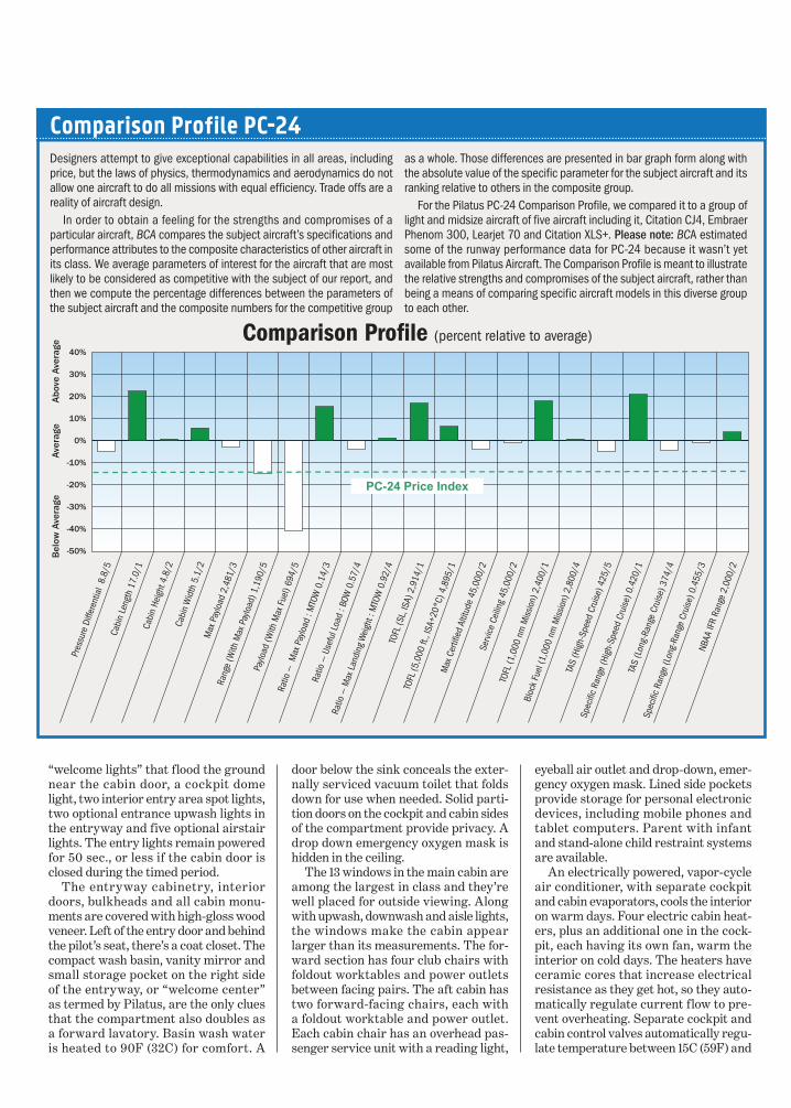
Comparison Profile PC-24Designers attempt to give exceptional capabilities in all areas, including price, but the laws of physics, thermodynamics and aerodynamics do not allow one aircraft to do all missions with equal efficiency. Trade offs are a reality of aircraft design. In order to obtain a feeling for the strengths and compromises of a particular aircraft, BCA compares the subject aircraft’s specifications and performance attributes to the composite characteristics of other aircraft in its class. We average parameters of interest for the aircraft that are most likely to be considered as competitive with the subject of our report, and then we compute the percentage differences between the parameters of the subject aircraft and the composite numbers for the competitive group
Comparison Pro�le (percent relative to average)
Pres
sure
Diff
eren
tial
8.8/
5Ca
bin
Leng
th 1
7.0/
1
Max
Pay
load
2,4
81/3
Rang
e (W
ith M
ax P
aylo
ad) 1
,190
/5Pa
yload
(With
Max
Fue
l) 69
4/5
Ratio
— M
ax P
aylo
ad :
MTO
W 0
.14/
3Ra
tio —
Use
ful L
oad
: BOW
0.5
7/4
Ratio
— M
ax L
andi
ng W
eigh
t : M
TOW
0.9
2/4
TOFL
(SL,
ISA)
2,9
14/1
TOFL
(5,0
00 ft
., IS
A+20
°C) 4
,895
/1M
ax C
erti�
ed A
ltitu
de 4
5,00
0/2
Serv
ice
Ceili
ng 4
5,00
0/2
TOFL
(1,0
00 n
m M
issio
n) 2
,400
/1
Bloc
k Fu
el (1
,000
nm
Miss
ion)
2,8
00/4
TAS
(Hig
h-Sp
eed
Crui
se) 4
25/5
Spec
i�c
Rang
e (H
igh-
Spee
d Cr
uise
) 0.4
20/1
TAS
(Lon
g-Ra
nge
Crui
se) 3
74/4
Spec
i�c
Rang
e (L
ong-
Rang
e Cr
uise
) 0.4
55/3
NBAA
IFR
Rang
e 2,
000/
2
Cabi
n He
ight
4.8
/2Ca
bin
Wid
th 5
.1/2
40%
30%
20%
10%
0%
-10%
-20%
-30%
-40%
-50%
PC-24 Price Index
Aver
age
Bel
ow A
vera
geA
bove
Ave
rage
as a whole. Those differences are presented in bar graph form along with the absolute value of the specific parameter for the subject aircraft and its ranking relative to others in the composite group. For the Pilatus PC-24 Comparison Profile, we compared it to a group of light and midsize aircraft of five aircraft including it, Citation CJ4, Embraer Phenom 300, Learjet 70 and Citation XLS+. Please note: BCA estimated some of the runway performance data for PC-24 because it wasn’t yet available from Pilatus Aircraft. The Comparison Profile is meant to illustrate the relative strengths and compromises of the subject aircraft, rather than being a means of comparing specific aircraft models in this diverse group to each other.
“welcome lights” that flood the ground near the cabin door, a cockpit dome light, two interior entry area spot lights, two optional entrance upwash lights in the entryway and five optional airstair lights. The entry lights remain powered for 50 sec., or less if the cabin door is closed during the timed period.
The entryway cabinetry, interior doors, bulkheads and all cabin monu-ments are covered with high-gloss wood veneer. Left of the entry door and behind the pilot’s seat, there’s a coat closet. The compact wash basin, vanity mirror and small storage pocket on the right side of the entryway, or “welcome center” as termed by Pilatus, are the only clues that the compartment also doubles as a forward lavatory. Basin wash water is heated to 90F (32C) for comfort. A
door below the sink conceals the exter-nally serviced vacuum toilet that folds down for use when needed. Solid parti-tion doors on the cockpit and cabin sides of the compartment provide privacy. A drop down emergency oxygen mask is hidden in the ceiling.
The 13 windows in the main cabin are among the largest in class and they’re well placed for outside viewing. Along with upwash, downwash and aisle lights, the windows make the cabin appear larger than its measurements. The for-ward section has four club chairs with foldout worktables and power outlets between facing pairs. The aft cabin has two forward-facing chairs, each with a foldout worktable and power outlet. Each cabin chair has an overhead pas-senger service unit with a reading light,
eyeball air outlet and drop-down, emer-gency oxygen mask. Lined side pockets provide storage for personal electronic devices, including mobile phones and tablet computers. Parent with infant and stand-alone child restraint systems are available.
An electrically powered, vapor-cycle air conditioner, with separate cockpit and cabin evaporators, cools the interior on warm days. Four electric cabin heat-ers, plus an additional one in the cock-pit, each having its own fan, warm the interior on cold days. The heaters have ceramic cores that increase electrical resistance as they get hot, so they auto-matically regulate current flow to pre-vent overheating. Separate cockpit and cabin control valves automatically regu-late temperature between 15C (59F) and
30C (86F) in each zone.Twin pyramid cabinets behind the
rear seats provide additional storage. The aircraft lacks a dedicated galley, so bring aboard a stocked ice chest, hot coffee thermos bottles and beverage cups, if you need refreshments on lon-ger trips.
Left and right aft bulkheads, plus a curtain, separate the main seating area
from the cargo compartment. Cargo nets may be installed at two different points to provide either 24.7- or 47.7-cu.-ft. baggage compartments for items weighing 66 lb. or less. Bulkier items must be tied down to the full-length seat rails.
For operators needing more passen-ger seats, Pilatus offers a six plus two executive chair layout that eliminates
the rear pyramid cabinets, moves back the aft bulkheads between passenger and cargo compartment and installs two additional chairs in the aft cabin. Small pyramid cabinets are installed ahead of the forward club grouping. A double club arrangement also is available, among other optional cabin layouts.
Pilatus offers individual and bundled options packages. The 105-lb., $424,900 Professional U.S. package includes cock-pit and cabin Wi-Fi, Honeywell Char-tlink for electronic Jeppesen charts, ADS-B In, L3 WX500 Stormscope, 2-D airport diagrams, Latitude S200 Sky-Node Iridium satcom, XM radio weather and entertainment receivers, separate L3 cockpit voice and flight data record-ers, integrated cabin management sys-tem for tablet control of cabin systems and entertainment, and Gogo Biz 3G ATG-2000 text, talk and internet ac-cess. Other options include additional AC power outlets and USB charging ports at every seat.
Let’s Go FlyingChief pilot Reto Aeschlimann was our guide and right-seat instructor for the evaluation flight. Walking around the aircraft, we were impressed with the ease of access to systems and indicators. Opening the left, forward nose compart-ment door, for instance, provides access to systems Battery 1 and various avion-ics components. Doors on the right side of the aircraft provide access to the oxy-gen bottle refill port, lavatory servicing, refueling/defueling panel and the aft start Battery 2. Remote engine oil level sensing on the EICAS alerts the crew of the need to replenish the systems.
Belting into the left seat, I was im-pressed with the human-centered de-sign of the flight deck. It’s one of the best we’ve seen and well-suited for a classic blindfold cockpit check because of the shape, position and movement of various controls. Normal is 12 o’clock on knobs, up on switches, levers forward, no aural alerts and dark annunciator buttons.
The crew seats have adjustments for longitudinal track, height, recline, thigh and back cushion support, armrest posi-tion and headrest height. A hand crank moves the rudder pedal position. Left and right USB power ports keep tab-let computers hosting EFB apps well charged.
The PC-24’s Advanced Cockpit Envi-ronment (ACE) design closely parallels that of the PC-12 NG, easing the upgrade
Pilot Report
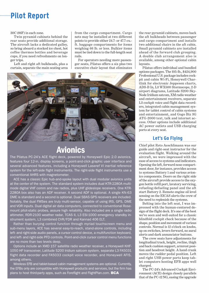
AvionicsThe Pilatus PC-24’s ACE flight deck, powered by Honeywell Epic 2.0 avionics, features four 12-in. display screens, a point-and-click graphic user interface and several advanced features, including a Honeywell Laseref VI inertial reference system for the left-side flight instruments. The right-side flight instruments use a conventional AHRS with magnetometer.
ACE has a classic Epic hub-and-spoke layout with dual modular avionics units at the center of the system. The standard system includes dual KTR-2280A multi-mode digital VHF comm and nav radios, plus UHF glideslope receivers. One KTR-2280A box also has an ADF receiver. A second ADF is optional. A single KN-63 DME is standard and a second is optional. Dual SBAS GPS receivers are included. Notably, the dual FMSes are truly multi-sensor, capable of using IRS, GPS, DME and VOR inputs. Dual digital air data computers, connected to conventional Rose-mount pitot-static probes, assure high reliability. Also included are a single radio altimeter, RDR-2100 weather radar, TCAS II, L3 ESI-1000 emergency standby in-strument system, L3 combined CVR/FDR and Kannad 406 ELT.
Rather than burying control function through myriad touchscreen menu and sub-menu layers, ACE has several easy-to-reach, stand-alone controls, including left- and right-side audio panels, a cursor control device, a multifunction keyboard, and left- and right-side PFD controls. Point-and-click cursor control menu functions are no more than two levels deep.
Options include an XMD 157 satellite radio weather receiver, a Honeywell KHF-1050 HF transceiver, Latitude S200 Iridium satcom system, separate L3 FA5031 flight data recorder and FA5033 cockpit voice recorder, and Honeywell AFIS, among others.
Wireless EFB and tablet-based cabin management systems are optional. Currently, the EFBs only are compatible with Honeywell products and services, but the firm has plans to host third-party apps, such as Foreflight and FlightPlan.com. BCA
transition. It’s powered by Honeywell Epic 2.0 avionics, the successor to the Apex system installed in the PC-12 NG. The cockpit has only a few mechanical circuit breakers dedicated to powering and protecting essential functions. Most electrical systems are tied to electronic, or virtual, circuit breakers.
ACE™ makes use of the electronic checklist a virtual must. Each item on the checklist automatically calls up the appropriate system schematic on the EICAS so that the flight crew can verify proper configuration and/or functional-ity of the aircraft step by step through color-coded diagrams. Many of ACE’s user interface conventions, particularly when programming the FMS, borrow heavily from Dassault’s EASy f light decks in Falcon Jets.
Many general aviation aircraft now have a runway performance computa-tion function loaded into their FMSes. But Pilatus elected to use Guru2, a stand-alone tablet app supplied by Fly-gprestanda AB in Malmö, Sweden, for this function. In contrast to many other such OEM-supplied airport perfor-mance apps with which we’ve struggled, Guru2 is considerably more discover-able and user friendly, in our opinion. It’s comprehensive, having a complete airport database, including runway di-mensions and alignment, runway slope and obstacles, plus full AFM aircraft performance numbers, including V speeds and runway requirements for each configuration and for both wet and dry surfaces.
PC-24 Prototype 3’s 11,533-lb. empty weight was close to Pilatus’ current es-timate for the average production air-craft. With Aeschlimann, me and typical test aircraft stores, zero fuel weight was 12,324 lb. Fuel weight was 4,300 lb. and ramp weight was 16,624 lb.
Guru2 asked for our inputs for weight and balance, wind, OAT, barometer and aircraft configuration, along with as-signed runway. It knew Buochs’ 1,475-ft. field elevation. We entered variable winds, a 24C OAT and 1014 MB barome-ter, along with 15-deg. flaps. It computed 90 KIAS for V1, 92 KIAS for rotation and 102 KIAS for V2. Flap retraction speed was 127 KIAS and OEI en route speed was 170 KIAS. Computed OEI takeoff distance was 3,679 ft. and Run-way 24 length was 6,562 ft.
To improve OEI second-segment climb performance for hot-and-high airport operations, Pilatus also will attain approval for flaps 8 deg. take-offs as a post-certification task.
We started the right engine on ground power to save the batteries. A twist of the overhead engine stop/run knob to the 12 o’clock position, a push of the overhead start button and the FADEC plus the UMS takes care of all the start chores. But we still monitored all engine start indications to provide adult supervision of the computers.
We set the stab at 2-deg. nose up for the aircraft’s 33% CG. Setting the stab pitch trim assures proper elevator re-sponse at takeoff rotation. With brakes released, it took a healthy push on the thrust levers to overcome the rolling re-sistance of the low-pressure tires. Once rolling, steering response through the rudder pedals was crisp, but differen-tial thrust and braking was required for tight turns.
Aligned with Runway 24, I advanced the thrust levers and engaged the au-tothrottles. The engines stabilized at 96.6% N1, producing moderate accel-eration. Initial rotation effort was hefty, as the main gear are well aft of the CG to assure a stable stance on the ground when loading the rear cargo bay. After
liftoff, though, pitch response was light and crisp, as was roll response with the help of the roll spoilers with flaps ex-tended and speed below 175 KIAS. With f laps retracted, I kept taking off my headset to check interior sound levels. After repeating that a half dozen times, I concluded that the PC-24 is the quiet-est midsize jet we’ve yet flown.
Using 200 KIAS for climb, we initially leveled off at FL 200 for airwork. Roll control effort becomes heavy as speed increases. The aircraft would be more pleasant to hand-fly at high speed if the electrically powered roll spoilers as-sisted the ailerons, in our opinion.
Pitch effort also was considerable at high speed, but that’s OK as it prevents over-control. It’s easy to stabilize the aircraft in steep turns using the flight path vector symbol on the PFD to set the correct pitch and the airspeed trend vector to prevent speed deviations.
Idle to maximum thrust changes also produce very little pitching moment due to the engine exhaust nozzle design. (See the “Engines” sidebar.)
Stall behavior is quite similar to that
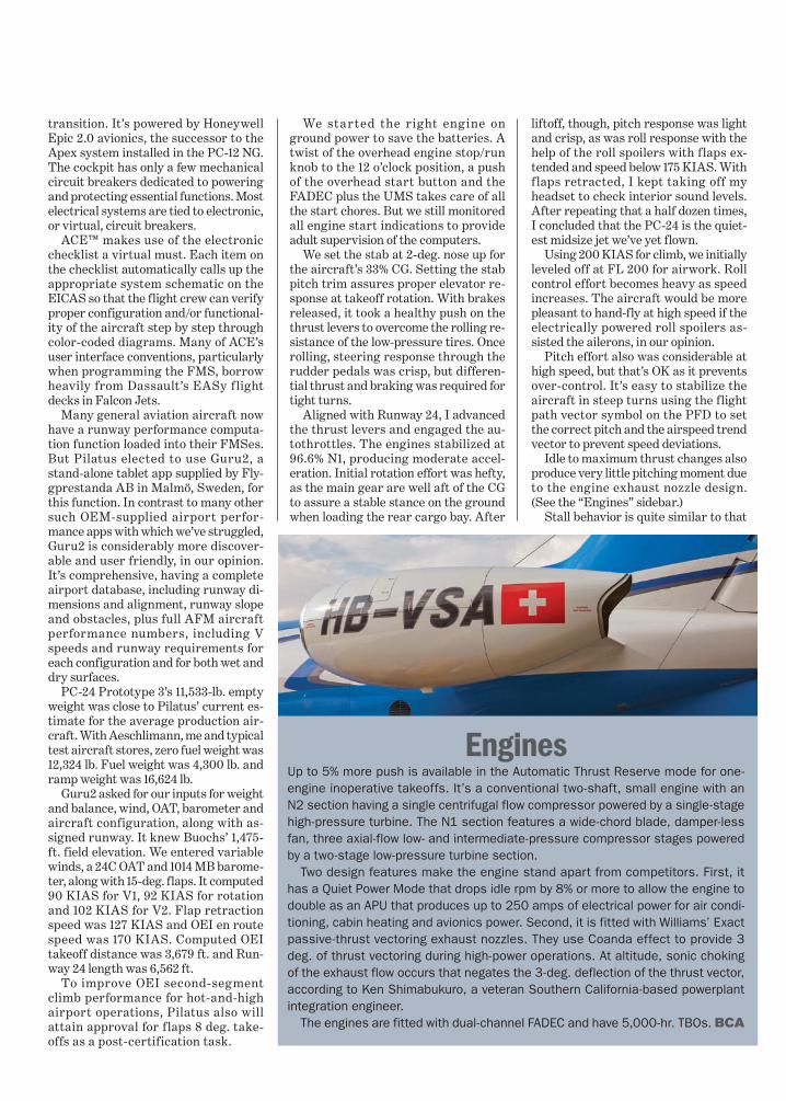
EnginesUp to 5% more push is available in the Automatic Thrust Reserve mode for one-engine inoperative takeoffs. It’s a conventional two-shaft, small engine with an N2 section having a single centrifugal flow compressor powered by a single-stage high-pressure turbine. The N1 section features a wide-chord blade, damper-less fan, three axial-flow low- and intermediate-pressure compressor stages powered by a two-stage low-pressure turbine section.
Two design features make the engine stand apart from competitors. First, it has a Quiet Power Mode that drops idle rpm by 8% or more to allow the engine to double as an APU that produces up to 250 amps of electrical power for air condi-tioning, cabin heating and avionics power. Second, it is fitted with Williams’ Exact passive-thrust vectoring exhaust nozzles. They use Coanda effect to provide 3 deg. of thrust vectoring during high-power operations. At altitude, sonic choking of the exhaust flow occurs that negates the 3-deg. deflection of the thrust vector, according to Ken Shimabukuro, a veteran Southern California-based powerplant integration engineer.
The engines are fitted with dual-channel FADEC and have 5,000-hr. TBOs. BCA
of the PC-12 NG, as are the indica-tions and stall warning and pro-tection system. At 16,200 lb. in the clean configuration, stall warning was triggered at 111 KIAS, signaled by stick shaker, an aural warning and two red “stall” annunciations on the PFD. The pusher fired at 99 KIAS, causing the nose to drop and prompting me to further re-duce pitch attitude, push forward the thrust levers and recover from the maneuver.
Pre-stall behavior at 16,000 lb. in the flaps 15-deg. takeoff and 33-deg. landing configurations was equally benign. Stick shaker and pusher occurred at 90 KIAS and 81 KIAS at flaps 15 deg. and 83 KIAS and 78 KIAS at flaps 33 deg. There wasn’t a hint of wing roll-off or adverse yaw during any of the maneuvers.
Using a 200 KIAS/Mach 0.59 climb schedule, we then climbed up to FL 450 for cruise and han-dling checks. Once level at a weight of 15,375 lb. and with the autopilot engaged, the aircraft stabilized at Mach 0.72 at ISA+3C, resulting in 416 KTAS with a fuel flow of 490 lb./hr. per engine.
It’s also easy to hand-fly the aircraft at altitude, should that become neces-sary. We turned off the yaw damper and excited Dutch roll with a moderate thump on a rudder pedal. The aircraft became mildly divergent, but as soon as I corrected with rudder input, it stabilized.
Rolling into a 60-deg. bank turn, the aircraft was buffet-free up to 2 Gs at Mach 0.71, the peak buffet boundary speed. As it slowed down to Mach 0.65 due to induced drag, the buffet bound-ary decreased.
Aircraft response to air brake exten-sion is another strong suit of the PC-24. The multifunction roll spoilers double as speed brakes. They produce considerable drag but very little airframe buffet as they’re located well outboard of the horizontal tail tips. The flight control system also has an air brake/stab trim interconnect function that virtually eliminates any pitch moments during exten-sion or retraction. Maximum de-scent rate at the 290 KIAS Vmo redline approaches 10,000 fpm, so the passengers will spend lit-tle time wearing the cup masks in the event of an emergency descent.
Below 20,000 ft. and 250 KIAS, the
landing gear may be extended to has-ten the descent. And below 200 KIAS, flaps may be extended to 15 deg. for even more drag. As with extending and re-tracting the airbrakes, there is a flap/stab interconnect that minimizes pitch moments when extending or retracting the flaps.
The PC-24 was designed to be as doc-ile as the PC-12, so our flight plan called for an approach and landing at Saanen Airport (LSGK), tightly nestled in the
Bernese Oberland foothills of the Swiss Alps, southwest of Lake Thun. The last time we landed at the airport was in a PC-12 NG with Pilatus test pilot Theddy Spichtig. This would be our first attempt in a jet.
Down at 7,500 ft., we picked our way around clouds, peaks and ridges at 180 KIAS along the Simme River until we spotted the airport. We hugged the hill on the north side of the airport until we passed the west end, then ex-tended flaps to 8 deg., slowed to 150 KIAS and made a tight turn at the west end of the airport to head toward Gstaad.
Reversing course over Gstaad, we extended landing gear and full f laps to make the plunge to the 3,307-ft. elevation airport and landing on Runway 26. It has a 1,050-ft. displaced threshold for obstacle clearance, leaving 3,443 ft. available for landing. At 14,500 lb., Vapp was 105 KIAS and Vref was 95 KIAS. Computing unfac-
tored landing distance was 2,350 ft.When we spotted the runway, we
were a little high and a little fast, but momentarily extending the airbrakes corrected both deviations. We crossed the displaced threshold on speed and touched down softly due to the long travel, trailing link landing gear and low-pressure main tires. With weight on wheels and wheel spin up, the ground spoilers automatically extended. Firm braking slowed the aircraft to taxi speed by midfield.
We slowly rolled to the west end of Runway 26, then reversed course and rolled back to the east end to let the brakes cool. The aircraft has steel brakes and no brake temperature indi-
cation. Aeschlimann said that, based on his experience, that would allow heat to dissipate suf-ficiently for takeoff.
For departure from Saanen at 14,400 lb. at 20C (68F) and using flaps 15 deg., V1 was 90 KIAS, rotation was 99 KIAS and V2 was 102. Takeoff field length was 2,090 ft.
We departed VFR and then picked up an IFR clearance back into Buochs via Willisau VOR (WIL) and then RONIX IAF passing over Lake Baldegger. We requested the RONIX RNAV ap-
proach that it limited to Category A and B aircraft. The PC-24’s slow approach
Pilot Report
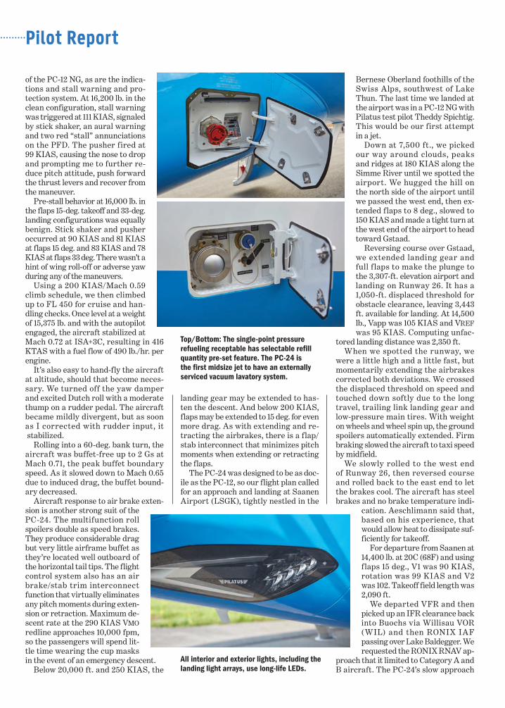
Top/Bottom: The single-point pressure refueling receptable has selectable refill quantity pre-set feature. The PC-24 is the first midsize jet to have an externally serviced vacuum lavatory system.
All interior and exterior lights, including the landing light arrays, use long-life LEDs.
maneuvering speeds easily qualify it as a Category B aircraft.
Following the procedure around Lake Zug and then down the north leg of Lake Lucerne, we descended to 2,550 ft. and spotted the Bürgenstock that masks Buochs. We canceled and maneuvered around the west side over Stansstad to align with Runway 06.
During the turn Aeschlimann pulled back the right throttle to simulated en-gine failure. Light rudder pressure kept the aircraft in balanced flight. At 200 ft. above the runway, we executed a simu-lated OEI go-around.
Initially, I pressed way too hard on the left rudder pedal. The rudder boost sys-tem using the yaw damper servo is quite powerful. I estimate that less than 50 lb. of pressure was needed to keep the ball in the center during the go-around.
We climbed to 3,000 ft. over Lake Lu-cerne and circled around the north side of the Bürgenstock, blind to the airport. Aeschlimann allowed me to use both engines for the final landing on Runway 06. At 13,500 lb., Vapp was 102 KIAS and Vref was 92 KIAS. At touchdown, we applied maximum brake pressure. This requires considerable foot pres-sure, similar to a maximum effort land-ing in an Embraer Legacy 650. The PC-24 stopped in about 2,600 ft. after crossing the landing threshold.
Conclusions? From a pilot’s per-spective, Pilatus’ first jet is one of the most docile, forgiving and predictable business aircraft we’ve flown. It’s well-suited to single-pilot operations.
It’s also one of the most integrated, sophisticated civil aircraft yet produced, having automation that’s designed to work for the flight crew rather than re-place them. The ACE flight deck, for instance, functions as an additional vir-tual flight crewmember who seeks to provide solutions rather than “what’s it doing now?” problems.
Nits to pick? We’d like to see simpler EFIS color conventions, such as magenta for computer-generated targets and data, cyan for pilot-entered targets and data, green for all active functions and white or gray for standby functions. The aircraft also could benefit from an optional head-up display. And lighter high-speed roll control forces would be a plus.
Price and ValueWe’ve often written that aircraft man-ufacturers seek to maximize all de-sign goals, but in the end, tradeoffs are inevitable. Glance please at the
accompanying Comparison Profile chart in which we gauge the PC-24 against its most closely priced competi-tors, including the Cessna Citation CJ4, Embraer Phenom 300, Learjet 70 and Citation XLS+.
The chart shows the PC-24’s selling points are its cabin volume, runway performance and fuel efficiency. Its shortcomings mainly are related to its empty weight increase relative to its relatively low maximum takeoff, landing and zero fuel weights. This at-tribute limits its range with maximum payload and payload with maximum fuel. With four passengers aboard, the aircraft now can fly 1,852 nm at high speed cruise or 2,000 nm at long range cruise, as shown in the accompanying Range/Payload Profile chart. Each ad-ditional 200-lb. passenger costs about 80 mi. of range.
But our charts only measure a limited number of performance attributes, so the PC-24 cannot be evaluated solely with those criteria. The charts don’t re-veal how quiet this aircraft is inside or the technology or high level of integra-tion of its systems and avionics.
Most obviously, it has a 17-sq.-ft. cargo door that provides access to a 90-cu.-ft. internal baggage bay and the rest of the cabin. Pilatus calls it the Super Versatile Jet for good reason. The plush execu-tive interior can be removed in minutes, allowing the aircraft to be configured as an air ambulance, a cargo-liner or a combi passenger-and-cargo jet.
As with the PC-12, this aircraft was designed to operate from unimproved runways. That’s going to open up thou-sands of landing facilities that have never seen jets. Operators will be able to shuttle between major airports and back-country strips all over the world.
The PC-24 is going to be an ideal upgrade for PC-12 loyalists. It’s also going to attract current light and me-dium jet operators looking for more versatility in their business aircraft. And Pilatus product support is sec-ond to none, according to several in-dustry surveys.
On balance, we believe that Pila-tus will deliver at least 2,000 PC-24 aircraft over the next two decades. It’s clearly on track to deliver 2,000 PC-12s, a slap in the face to doubters who said it would never build more than 200. The future success of the PC-24 would be a f itting tribute to a small Swiss company that’s been refuting skeptics for the past quarter century. BCA
Pilatus PC-24 Specifications
BCA Equipped Price .......... $8,900,000
Characteristics Wing Loading ............................ 54.9Power Loading ..........................2.68 Noise (EPNdB) .......... 90.9/77.5/91.5
Seating ................................. 1+8/11
Dimensions (ft./m) Internal Length ..........................17.0/5.2 Height ............................ 5.1/1.6 Width (maximum) ............ 5.5/1.7 Width (floor) ....................3.8/1.2
ThrustEngine .............. 2 WMS FJ44-4A-QPM Output/Flat Rating OAT°C ...............3,420 lb. ea./ISA+8CTBO ..................................5,000 hr.
Weights (lb./kg) Max Ramp .................. 18,398/8,345 Max Takeoff ............... 18,298/8,300 Max Landing................ 16,579/7,520 Zero Fuel .....................14,220/6,450BOW ...........................11,739/5,325 Max Payload ................. 2,481/1,125 Useful Load ...................6,659/3,021 Executive Payload ...............800/363 Max Fuel .......................5,964/2,705 Payload with Max Fuel ........ 695/315 Fuel with Max Payload ...4,178/1,895 Fuel with Executive Payload ..... 5,859/2,658
LimitsMmo .......................................0.740FL/Vmo ...........................FL 280/290PSI ............................................. 8.8
ClimbTime to FL 450 ...................... 24 min. FAR 25 OEI rate (fpm) ...................665FAR 25 OEI gradient (ft./nm) .........379
Ceilings (ft./m)Certificated ...............45,000/20,412 All-Engine Service ......45,000/20,412Engine-Out Service ..30,000/13,608 Sea Level Cabin ........23,500/10,660
Certification ...FAR 23 CC / EASA 23 CC 2017
279836
Copyright © 2018 by InformaFor more information on use of this content, contact Wright’s Media at 877-652-5295.