Embed Size (px)
Citation preview
Pilot Re-Lining of the injector well Žu-111
for EOR Project of CO2/water injection
Authors: Josip Hudek, Tomislav Janton, Darko Brkljačić, Željko Habijanec, Željko Bolarić
Challenges and Future Technologies in EOR Implementation
Szolnok, April 23-24, 2013
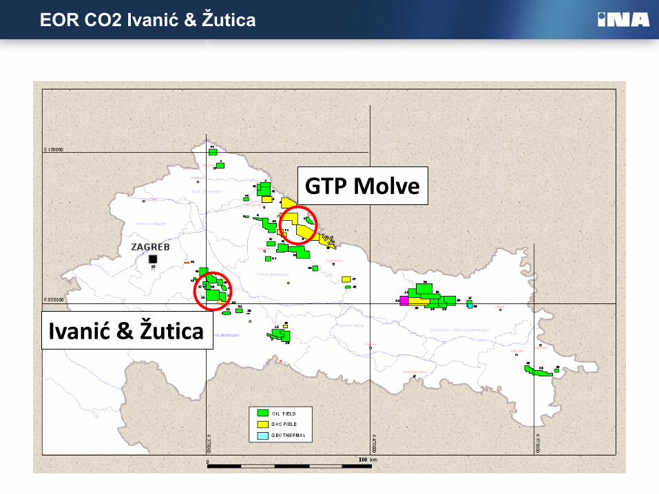
EOR CO2 Ivanić & Žutica
GTP Molve
Ivanić & Žutica
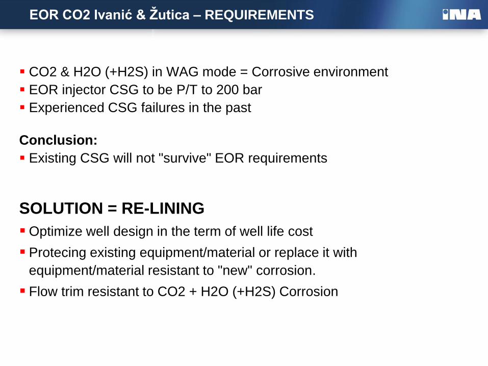
EOR CO2 Ivanić & Žutica – REQUIREMENTS
CO2 & H2O (+H2S) in WAG mode = Corrosive environment
EOR injector CSG to be P/T to 200 bar
Experienced CSG failures in the past
Conclusion:
Existing CSG will not "survive" EOR requirements
SOLUTION = RE-LINING
Optimize well design in the term of well life cost
Protecing existing equipment/material or replace it with
equipment/material resistant to "new" corrosion.
Flow trim resistant to CO2 + H2O (+H2S) Corrosion
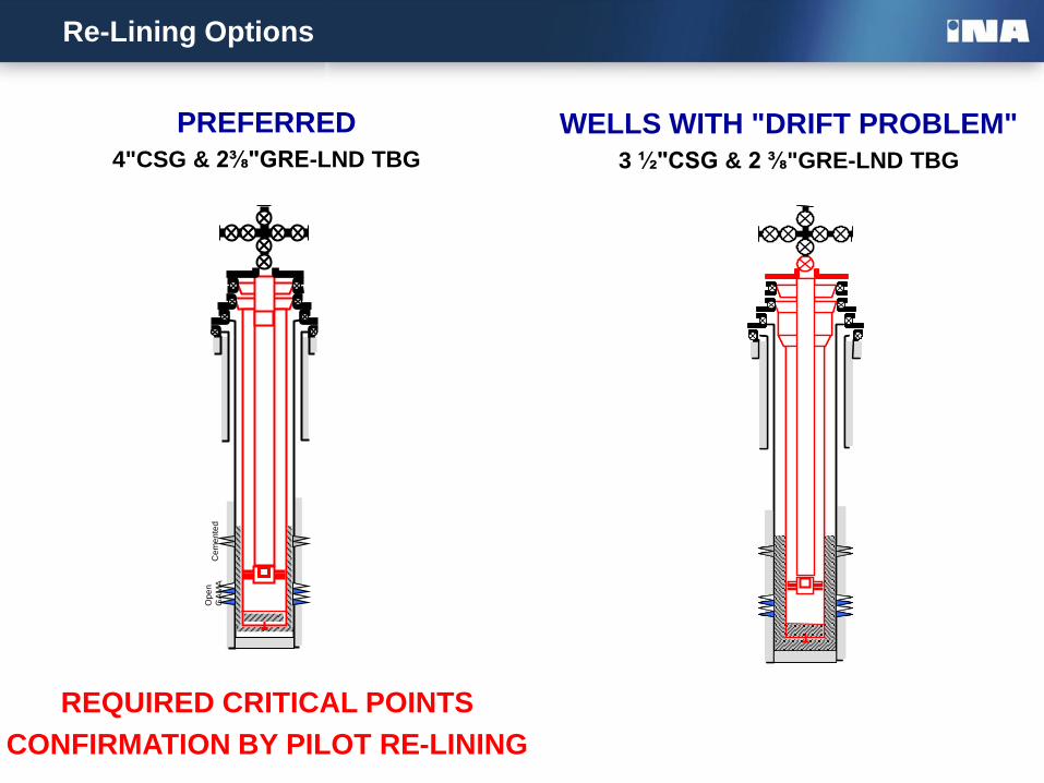
Re-Lining Options
PREFERRED
4"CSG & 2⅜"GRE-LND TBG
Op
en
GA
MA
C
em
en
ted
WELLS WITH "DRIFT PROBLEM"
3 ½"CSG & 2 ⅜"GRE-LND TBG
REQUIRED CRITICAL POINTS
CONFIRMATION BY PILOT RE-LINING
New CO2
resistant CMT
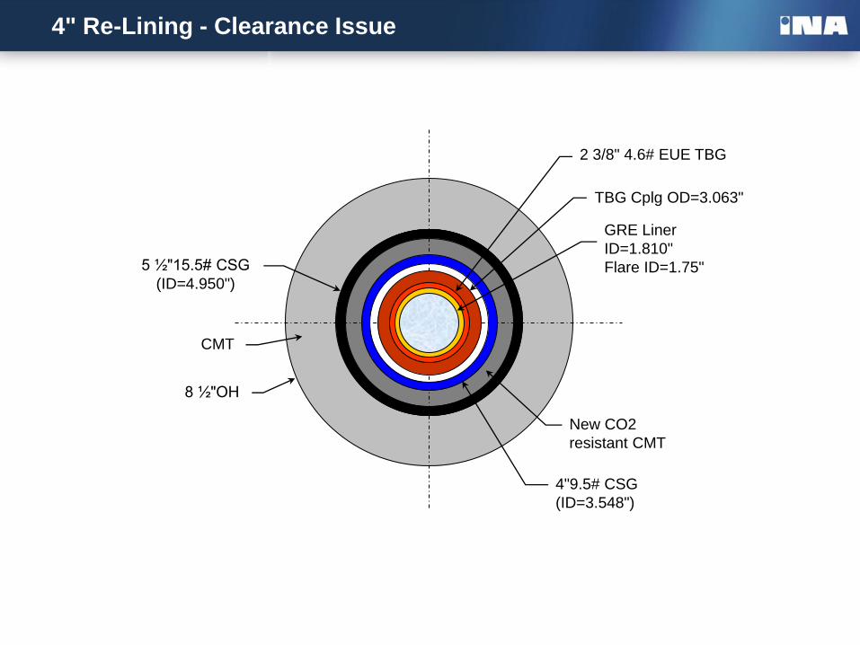
4" Re-Lining - Clearance Issue
8 ½"OH
CMT
5 ½"15.5# CSG
(ID=4.950")
4"9.5# CSG
(ID=3.548")
2 3/8" 4.6# EUE TBG
TBG Cplg OD=3.063"
GRE Liner
ID=1.810"
Flare ID=1.75"
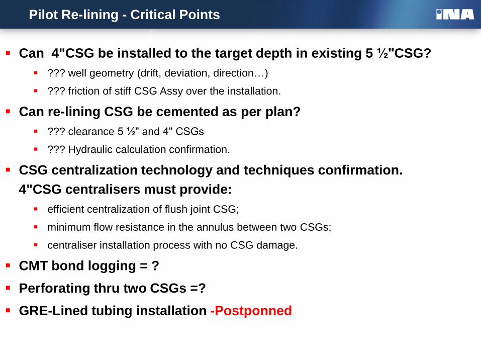
Pilot Re-lining - Critical Points
Can 4"CSG be installed to the target depth in existing 5 ½"CSG?
??? well geometry (drift, deviation, direction…)
??? friction of stiff CSG Assy over the installation.
Can re-lining CSG be cemented as per plan?
??? clearance 5 ½" and 4" CSGs
??? Hydraulic calculation confirmation.
CSG centralization technology and techniques confirmation.
4"CSG centralisers must provide:
efficient centralization of flush joint CSG;
minimum flow resistance in the annulus between two CSGs;
centraliser installation process with no CSG damage.
CMT bond logging = ?
Perforating thru two CSGs =?
GRE-Lined tubing installation -Postponned
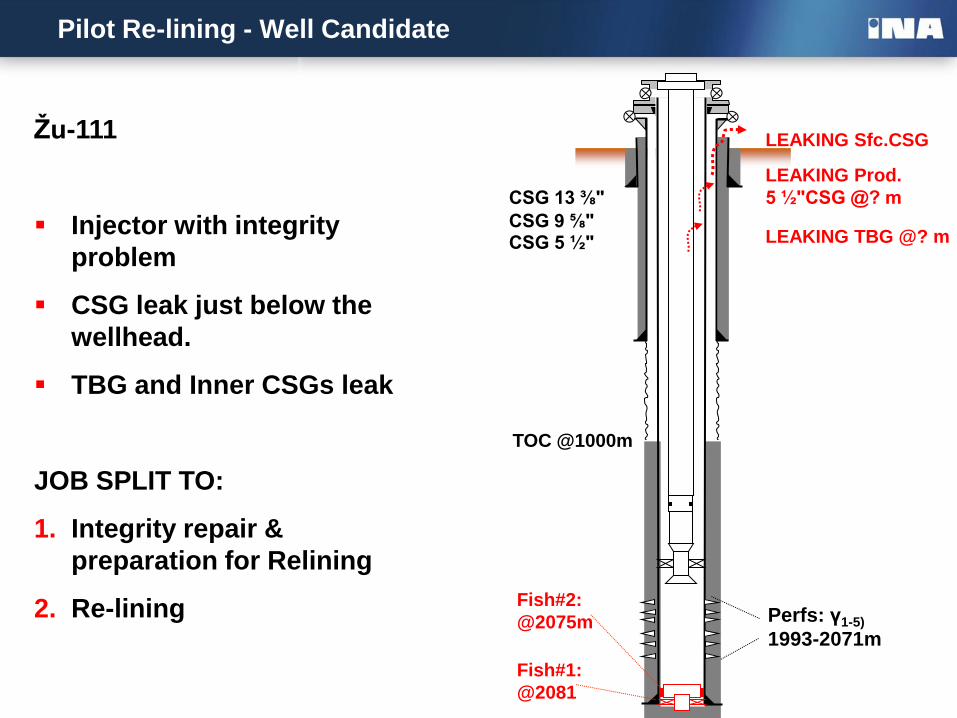
Žu-111
Injector with integrity
problem
CSG leak just below the
wellhead.
TBG and Inner CSGs leak
JOB SPLIT TO:
1. Integrity repair &
preparation for Relining
2. Re-lining
Pilot Re-lining - Well Candidate
CSG 5 ½" CSG 9 ⅝"
TOC @1000m
CSG 13 ⅜"
Fish#1:
@2081
Fish#2:
@2075m
LEAKING Sfc.CSG
LEAKING Prod.
5 ½"CSG @? m
LEAKING TBG @? m
Perfs: γ1-5)
1993-2071m
Rig Entry#1
Rig Entry#1: Integrity repair & preparation for Relining
TASKS:
Completion retrieving
Wellbore drifting & cleanout
Integrity repair
Suspension up to the Rig Entry#2
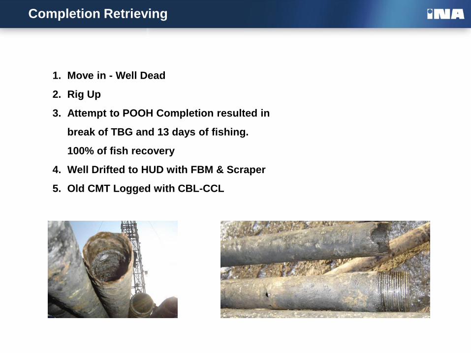
Completion Retrieving
1. Move in - Well Dead
2. Rig Up
3. Attempt to POOH Completion resulted in
break of TBG and 13 days of fishing.
100% of fish recovery
4. Well Drifted to HUD with FBM & Scraper
5. Old CMT Logged with CBL-CCL
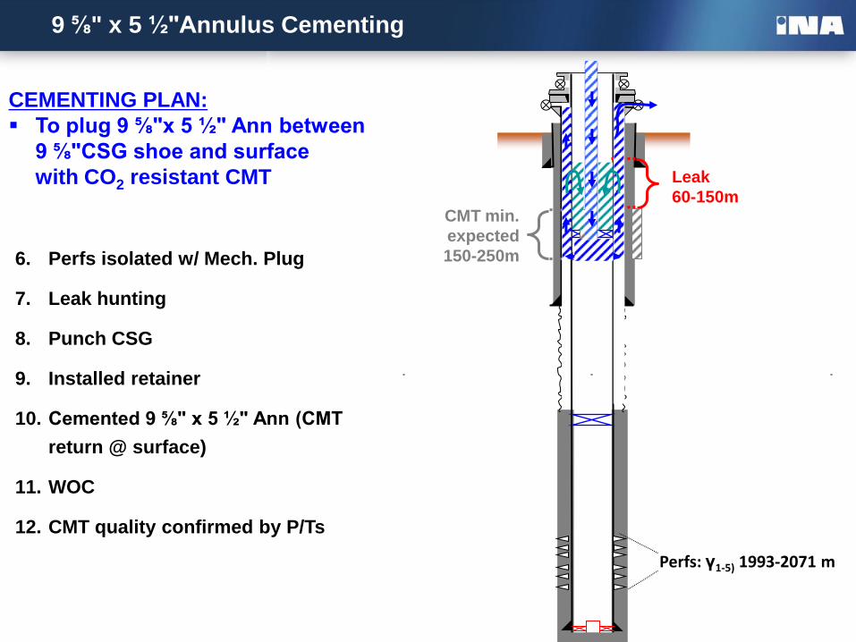
9 ⅝" x 5 ½"Annulus Cementing
Leak
60-150m CMT min.
expected
150-250m
CEMENTING PLAN:
To plug 9 ⅝"x 5 ½" Ann between
9 ⅝"CSG shoe and surface
with CO2 resistant CMT
6. Perfs isolated w/ Mech. Plug
7. Leak hunting
8. Punch CSG
9. Installed retainer
10. Cemented 9 ⅝" x 5 ½" Ann (CMT
return @ surface)
11. WOC
12. CMT quality confirmed by P/Ts
Perfs: γ1-5) 1993-2071 m
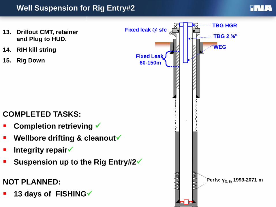
Well Suspension for Rig Entry#2
5 ½"CSG shoe @2129 m
Fixed Leak
60-150m
Fixed leak @ sfc TBG HGR
TBG 2 ⅜"
WEG
13. Drillout CMT, retainer and Plug to HUD.
14. RIH kill string
15. Rig Down
Perfs: γ(1-5) 1993-2071 m
COMPLETED TASKS:
Completion retrieving
Wellbore drifting & cleanout
Integrity repair
Suspension up to the Rig Entry#2
NOT PLANNED:
13 days of FISHING
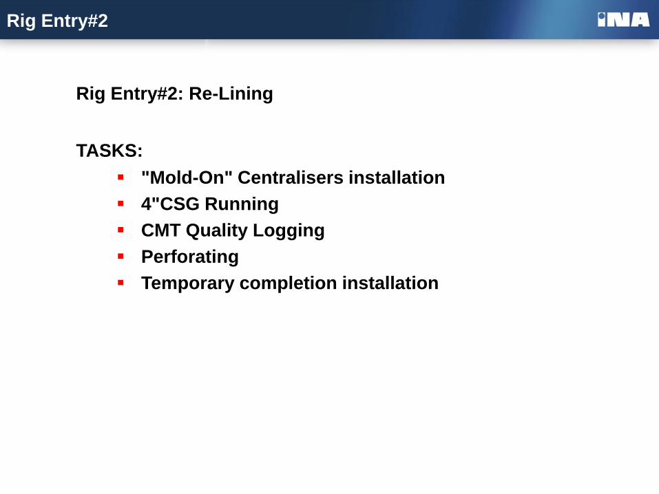
Rig Entry#2
Rig Entry#2: Re-Lining
TASKS:
"Mold-On" Centralisers installation
4"CSG Running
CMT Quality Logging
Perforating
Temporary completion installation
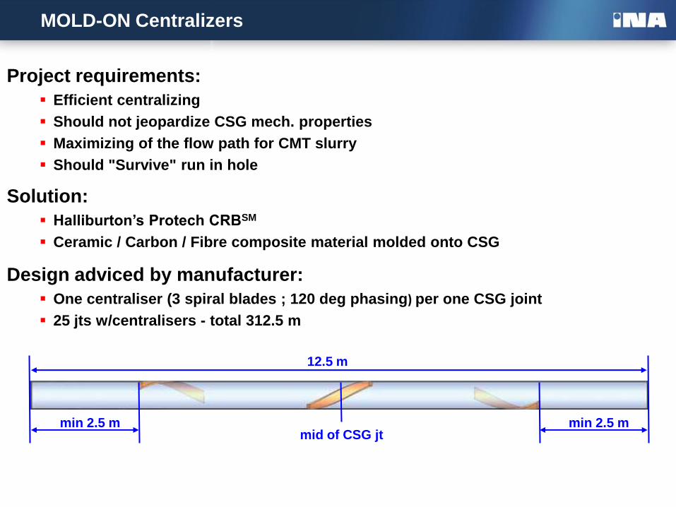
MOLD-ON Centralizers
Project requirements:
Efficient centralizing
Should not jeopardize CSG mech. properties
Maximizing of the flow path for CMT slurry
Should "Survive" run in hole
Solution:
Halliburton’s Protech CRBSM
Ceramic / Carbon / Fibre composite material molded onto CSG
Design adviced by manufacturer:
One centraliser (3 spiral blades ; 120 deg phasing) per one CSG joint
25 jts w/centralisers - total 312.5 m
12.5 m
min 2.5 m min 2.5 m mid of CSG jt
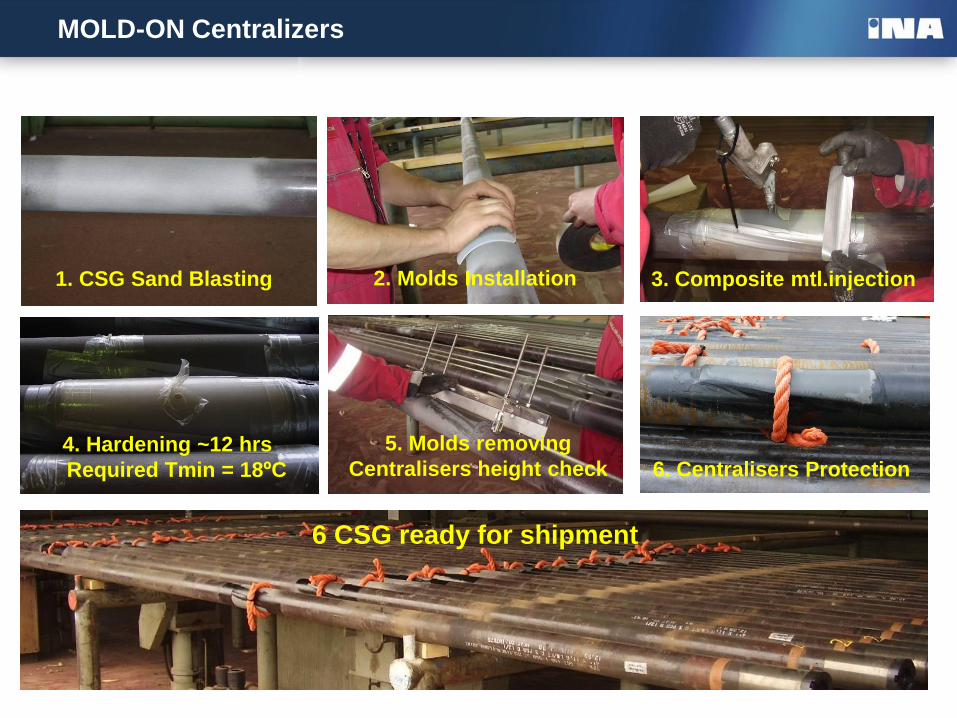
MOLD-ON Centralizers
6 CSG ready for shipment
3. Composite mtl.injection
5. Molds removing
Centralisers height check
1. CSG Sand Blasting 2. Molds Installation
4. Hardening ~12 hrs
Required Tmin = 18ºC 6. Centralisers Protection
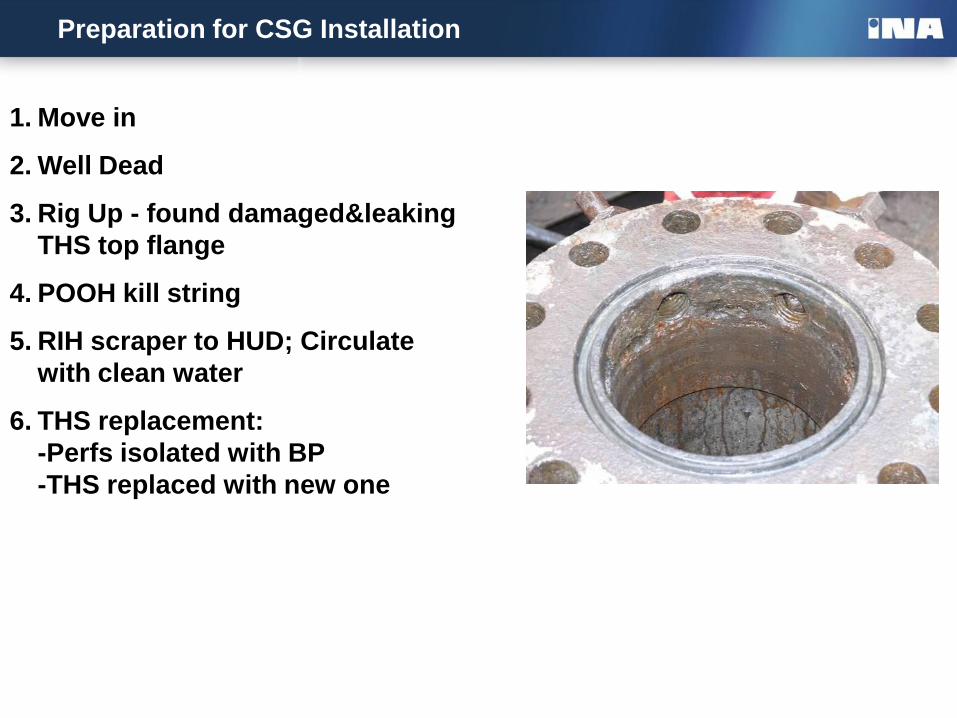
Preparation for CSG Installation
1. Move in
2. Well Dead
3. Rig Up - found damaged&leaking
THS top flange
4. POOH kill string
5. RIH scraper to HUD; Circulate
with clean water
6. THS replacement:
-Perfs isolated with BP
-THS replaced with new one
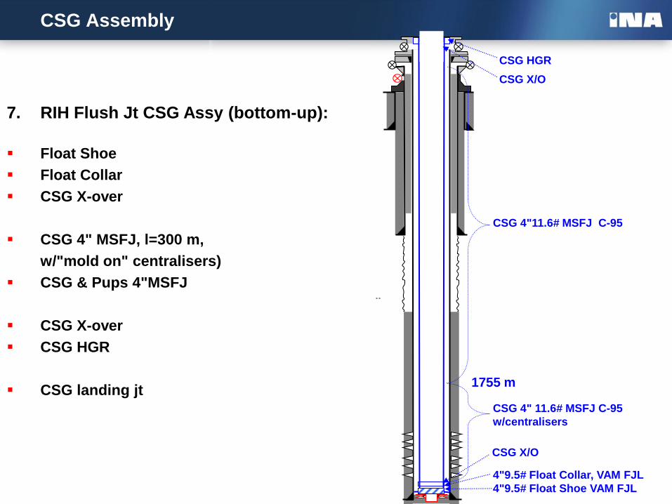
CSG Assembly
7. RIH Flush Jt CSG Assy (bottom-up):
Float Shoe
Float Collar
CSG X-over
CSG 4" MSFJ, l=300 m,
w/"mold on" centralisers)
CSG & Pups 4"MSFJ
CSG X-over
CSG HGR
CSG landing jt
CSG HGR
CSG X/O
CSG 4"11.6# MSFJ C-95
1755 m
CSG 4" 11.6# MSFJ C-95
w/centralisers
4"9.5# Float Collar, VAM FJL
4"9.5# Float Shoe VAM FJL
CSG X/O
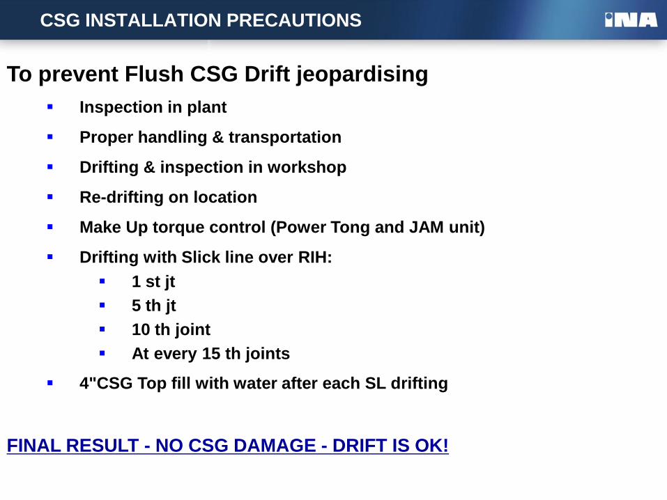
CSG INSTALLATION PRECAUTIONS
To prevent Flush CSG Drift jeopardising
Inspection in plant
Proper handling & transportation
Drifting & inspection in workshop
Re-drifting on location
Make Up torque control (Power Tong and JAM unit)
Drifting with Slick line over RIH:
1 st jt
5 th jt
10 th joint
At every 15 th joints
4"CSG Top fill with water after each SL drifting
FINAL RESULT - NO CSG DAMAGE - DRIFT IS OK!
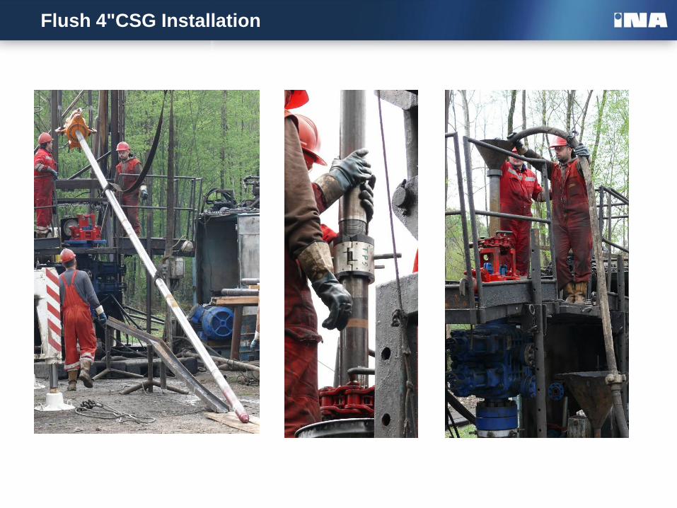
Flush 4"CSG Installation
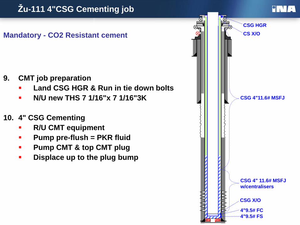
Žu-111 4"CSG Cementing job
Mandatory - CO2 Resistant cement
CSG HGR
CS X/O
CSG 4"11.6# MSFJ
CSG 4" 11.6# MSFJ
w/centralisers
4"9.5# FC
4"9.5# FS
CSG X/O
9. CMT job preparation
Land CSG HGR & Run in tie down bolts
N/U new THS 7 1/16"x 7 1/16"3K
10. 4" CSG Cementing
R/U CMT equipment
Pump pre-flush = PKR fluid
Pump CMT & top CMT plug
Displace up to the plug bump
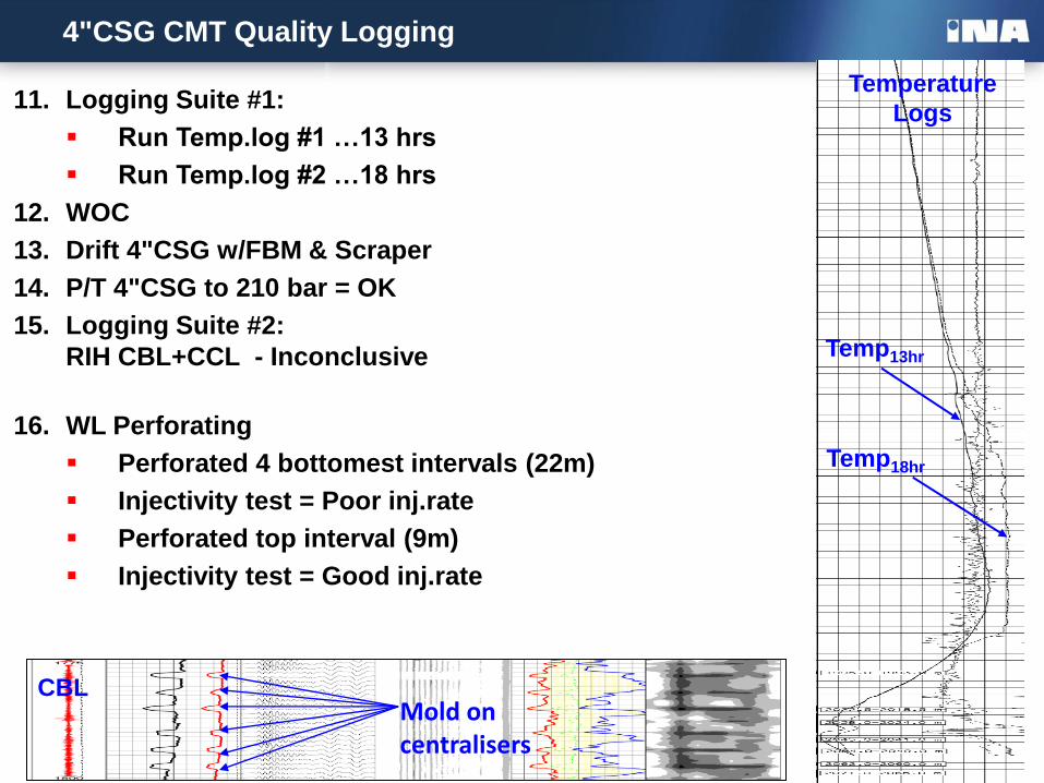
4"CSG CMT Quality Logging
11. Logging Suite #1:
Run Temp.log #1 …13 hrs
Run Temp.log #2 …18 hrs
12. WOC
13. Drift 4"CSG w/FBM & Scraper
14. P/T 4"CSG to 210 bar = OK
15. Logging Suite #2:
RIH CBL+CCL - Inconclusive
16. WL Perforating
Perforated 4 bottomest intervals (22m)
Injectivity test = Poor inj.rate
Perforated top interval (9m)
Injectivity test = Good inj.rate
Temp13hr
Temp18hr
Temperature
Logs
CBL Mold on centralisers
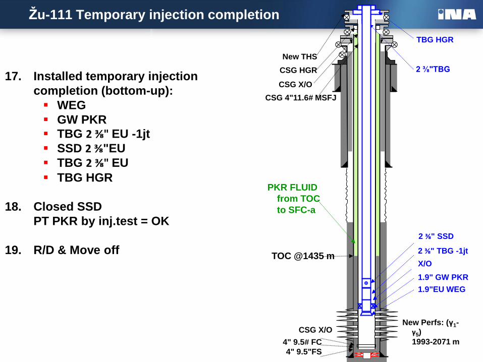
Žu-111 Temporary injection completion
17. Installed temporary injection
completion (bottom-up):
WEG
GW PKR
TBG 2 ⅜" EU -1jt
SSD 2 ⅜"EU
TBG 2 ⅜" EU
TBG HGR
18. Closed SSD
PT PKR by inj.test = OK
19. R/D & Move off
TBG HGR
2 ⅜"TBG
4" 9.5# FC
4" 9.5"FS
CSG X/O
CSG 4"11.6# MSFJ
TOC @1435 m
PKR FLUID
from TOC
to SFC-a
CSG HGR
CSG X/O
New THS
2 ⅜" TBG -1jt
X/O
1.9" GW PKR
1.9"EU WEG
2 ⅜" SSD
New Perfs: (γ1-γ5)
1993-2071 m
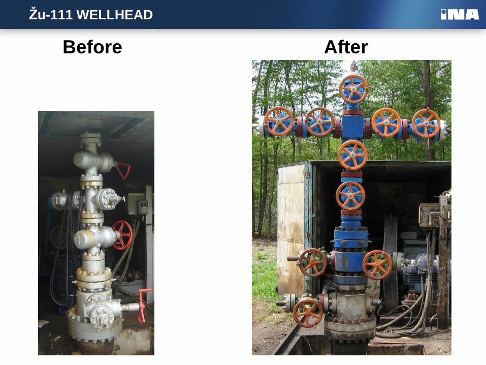
Žu-111 WELLHEAD
Before After
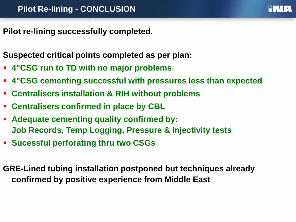
Pilot Re-lining - CONCLUSION
Pilot re-lining successfully completed.
Suspected critical points completed as per plan:
4"CSG run to TD with no major problems
4"CSG cementing successful with pressures less than expected
Centralisers installation & RIH without problems
Centralisers confirmed in place by CBL
Adequate cementing quality confirmed by:
Job Records, Temp Logging, Pressure & Injectivity tests
Sucessful perforating thru two CSGs
GRE-Lined tubing installation postponed but techniques already
confirmed by positive experience from Middle East
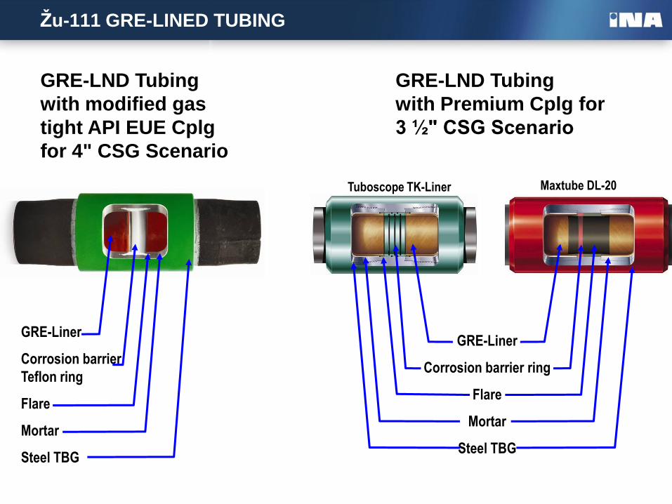
Žu-111 GRE-LINED TUBING
GRE-Liner
Corrosion barrier ring
Flare
Mortar
Steel TBG
Maxtube DL-20 Tuboscope TK-Liner
GRE-LND Tubing
with Premium Cplg for
3 ½" CSG Scenario
GRE-LND Tubing
with modified gas
tight API EUE Cplg
for 4" CSG Scenario
GRE-Liner
Corrosion barrier
Teflon ring
Flare
Mortar
Steel TBG
CSG X-over 4"9.5# FC, VAM FJL
4"9.5# FS, VAM FJL
CSG 4"11.6# MSFJ
w/centralisers
CSG 4"11.6# MSFJ
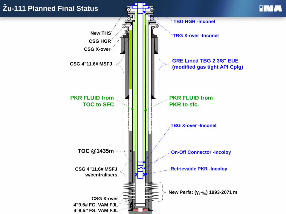
Žu-111 Planned Final Status
TOC @1435m
PKR FLUID from
TOC to SFC
CSG HGR
CSG X-over
New THS
New Perfs: (γ1-γ5) 1993-2071 m
TBG HGR -Inconel
TBG X-over -Inconel
TBG X-over -Inconel
On-Off Connector -Incoloy
Retrievable PKR -Incoloy
PKR FLUID from
PKR to sfc.
GRE Lined TBG 2 3/8" EUE
(modified gas tight API Cplg)
Questions
Thanks for Your
Attention
Questions…