Embed Size (px)
Citation preview
Pilot Operating Handbook Airplane Registration Number ______________________ Airplane Serial Number ______________________ REMOS Order No. 104178, dated May 2015
G3-8 MA FM 6200 Î R02
Introduction
Introduction i
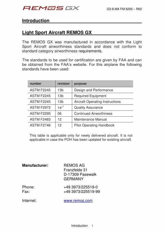
Light Sport Aircraft REMOS GX The REMOS GX was manufactured in accordance with the Light Sport Aircraft airworthiness standards and does not conform to standard category airworthiness requirements. The standards to be used for certification are given by FAA and can be obtained from thg"HCCÓu"ygdukvg0"Hqt" vjku"cktrncpg" vjg" hqnnqykpi"standards have been used:
number revision purpose
ASTM F2245 13b Design and Performance
ASTM F2245 13b Required Equipment
ASTM F2245 13b Aircraft Operating Instructions
ASTM F2972 14g1 Quality Assurance
ASTM F2295 06 Continued Airworthiness
ASTM F2483 12 Maintenance Manual
ASTM F2746 12 Pilot Operating Handbook
This table is applicable only for newly delivered aircraft. It is not applicable in case the POH has been updated for existing aircraft.
Manufacturer: REMOS AG Franzfelde 31 D-17309 Pasewalk GERMANY
Phone: +49 3973/225519-0 Fax: +49 3973/225519-99 Internet: www.remos.com
G3-8 MA FM 6200 Î R02
Introduction
Introduction ii
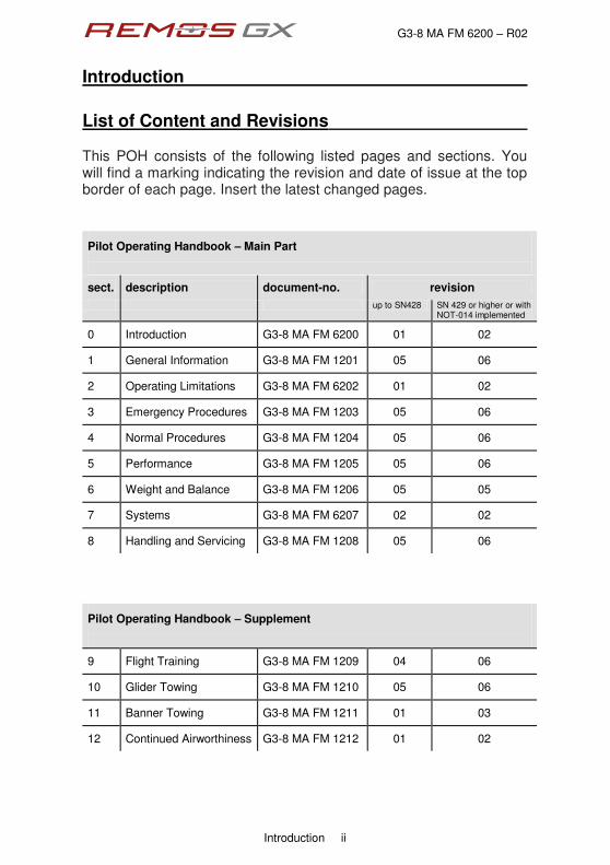
List of Content and Revisions This POH consists of the following listed pages and sections. You will find a marking indicating the revision and date of issue at the top border of each page. Insert the latest changed pages.
Pilot Operating Handbook Î Main Part
sect. description document-no. revision
up to SN428 SN 429 or higher or with NOT-014 implemented
0 Introduction G3-8 MA FM 6200 01 02
1 General Information G3-8 MA FM 1201 05 06
2 Operating Limitations G3-8 MA FM 6202 01 02
3 Emergency Procedures G3-8 MA FM 1203 05 06
4 Normal Procedures G3-8 MA FM 1204 05 06
5 Performance G3-8 MA FM 1205 05 06
6 Weight and Balance G3-8 MA FM 1206 05 05
7 Systems G3-8 MA FM 6207 02 02
8 Handling and Servicing G3-8 MA FM 1208 05 06
Pilot Operating Handbook Î Supplement
9 Flight Training G3-8 MA FM 1209 04 06
10 Glider Towing G3-8 MA FM 1210 05 06
11 Banner Towing G3-8 MA FM 1211 01 03
12 Continued Airworthiness G3-8 MA FM 1212 01 02
G3-8 MA FM 6200 Î R02
Introduction
Introduction iii
Remarks and Alterations Please make a notation below if any changes have been made to this manual or to the plane. This manual is an important document for the pilot in command to ensure safe operation of the aircraft. Therefore it is recommended to keep this Operating Handbook updated with the newest information available. You can get the latest updates of this manual from your dealer or directly from the ocpwhcevwtgtÓu"jqogrcig0
no. page concern date sign

G3-8 MA FM 6200 Î R02
Introduction
Introduction iv
Views
Wingspan 30.6 ft
Heig
ht 7
,.5 ft
Overall Length 21.3 ft
G3-8 MA FM 1201 - R06
1 General Information
General Information 1 - 1
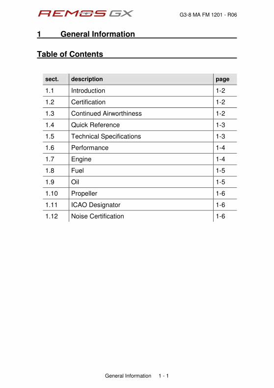
Table of Contents
sect. description page
1.1 Introduction 1-2
1.2 Certification 1-2
1.3 Continued Airworthiness 1-2
1.4 Quick Reference 1-3
1.5 Technical Specifications 1-3
1.6 Performance 1-4
1.7 Engine 1-4
1.8 Fuel 1-5
1.9 Oil 1-5
1.10 Propeller 1-6
1.11 ICAO Designator 1-6
1.12 Noise Certification 1-6
G3-8 MA FM 1201 - R06
1 General Information
General Information 1 - 2
1.1 Introduction This Operating Handbook is designed to help enable a safe and successful completion of each flight with the REMOS GX. It provides you with all necessary information for regular maintenance and operation of the aircraft. Therefore we recommend that the pilot keep this Operating Handbook updated with the newest information available. You can get the latest version of this Handbook from your nqecn"fgcngt"qt"fktgevn{"htqo"vjg"ocpwhcevwtgtÓu"jqogrcig0
1.2 Certification The REMOS GX was manufactured in accordance with the Light Sport Aircraft airworthiness standards and does not conform to standard category airworthiness requirements.
1.3 Continued Airworthiness Technical publications for continued airworthiness are released on the REMOS website www.remos.com and they may be downloaded free of charge. Bombardier-Rotax releases technical publications on their website www.flyrotax.com from which they may be downloaded free of charge. Documentation update for avionics may be downloaded on www.dynonavionics.com and www.garmin.com. It is the responsibility of the owner/operator of the aircraft to keep the aircraft and its documentation up to date and to comply with all technical publications.

G3-8 MA FM 1201 - R06
1 General Information
General Information 1 - 3
1.4 Quick Reference Type: Full composite carbon fiber aircraft with two seats. Design: High wing design with struts, front mounted engine
and propeller, traditional stabilizer concept, differential ailerons. Electrically operated flaps (0° to 40°), electric elevator trim, three-wheel landing gear with steerable nose wheel. Main gear with hydraulic disc brakes. The cabin is equipped with two seats side by side and can be entered and exited by doors on the left and right side of the fuselage.
Layout: Main components are built in half shells from
composite fiber material, which are bonded together (carbon fiber, Kevlar and glass fiber).
1.5 Technical Specifications
wingspan 30 ft 6 in
length 21 ft 3 in
height 7 ft 5 in
wing area 118 sq ft
MTOW 1,320 lb
wing loading 11 lb/sq ft

G3-8 MA FM 1201 - R06
1 General Information
General Information 1 - 4
1.6 Performance This section shall give a summary of the performance of the REMOS GX. Detailed performance data is given in section 5 of this Pilot Operating Handbook.
top speed at 3,00 ft 115 kTAS @° 5.500 rpm (*)
cruise speed at 3,000 ft 102 kTAS @° 5.000 rpm (*)
range at 3,000 ft 347 nm @° 5,000 rpm (*)
endurance at 3,000 ft 3,4 h @° 5.000 rpm (*)
rate of climb at VX 780 ft/min @ VX = 51 kIAS (*)
rate of climb at VY 840 ft/min @ VY = 60 kIAS (*)
stall speed clean 44 kIAS
stall speed flaps 40 deg 42 kIAS
[*] Sensenich or Neuform propeller, range and endurance incl. 30min reserve
1.7 Engine
manufacturer Bombardier-Rotax
engine type 912 UL-S2
max. power take-off 73.6 kW / 100 HP max. cont. 69.9 kW / 95 HP
max. engine speed take-off 5,800 rpm
continuous 5,500 rpm
gear ratio 2.43 : 1
slipper clutch optional
coolant BASF Glysantin Protect Plus/G48
mixing ratio 1:1 (Glysantin : water)

G3-8 MA FM 1201 - R06
1 General Information
General Information 1 - 5
1.8 Fuel
usable fuel quantity 21 US gallons
total fuel quantity 22 US gallons
fuel qualities AVGAS, MOGAS or min. AKI 91, ideally free of ethanol
NOTE
Please refer to REMOS notification NOT-001 and ROTAX SI-912-016/SI-914-019 for further information on suitable engine fluids (fuel, oil, cooling liquid, additives, etc). Have a frequent look on www.flyrotax.com and on www.remos.com for the latest information.
1.9 Oil
engine oil synthetic or semi-synthetic
oil rating API-SG or higher
engine oil capacity min. 2.1 qts
max. 3.1 qts
recommended oil AeroShell Sport PLUS 4 10W-40
NOTE
Please refer to REMOS notification NOT-001 and ROTAX SI-912-016/SI-914-019 for further information on suitable engine fluids (fuel, oil, cooling liquid, additives, etc). Have a frequent look on www.flyrotax.com and on www.remos.com for the latest information.
G3-8 MA FM 1201 - R06
1 General Information
General Information 1 - 6
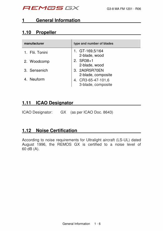
1.10 Propeller
manufacturer type and number of blades
1. FIii. Tonini 2. Woodcomp 3. Sensenich 4. Neuform
1. GT-169,5/164 2-blade, wood
2. SR38+1 2-blade, wood
3. 2A0R5R70EN 2-blade, composite
4. CR3-65-47-101,6 3-blade, composite
1.11 ICAO Designator ICAO Designator: GX (as per ICAO Doc. 8643)
1.12 Noise Certification According to noise requirements for Ultralight aircraft (LS-UL) dated August 1996, the REMOS GX is certified to a noise level of 60 dB (A).

G3-8 MA FM 6202 - R02
2 Operating Limitations
Operating Limitations 2 - 1
Table of Contents
sect. description page
2.1 Reference Airspeeds 2-2
2.2 Stalling Speeds at Maximum Takeoff Weight 2-3
2.3 Flap Extended Speed Range 2-3
2.4 Maximum Maneuvering Speed 2-3
2.5 Never Exceed Speed 2-4
2.6 Maximum Wind Velocity for Tie-Down 2-4
2.7 Crosswind and Wind Limitations 2-4
2.8 Maximum Parachute Deploy Airspeed 2-5
2.9 Service Ceiling 2-5
2.10 Load Factors 2-5
2.11 Maximum Structure Temperature 2-5
2.12 Prohibited Maneuvers 2-5
2.13 Approved Flight Maneuvers 2-6
2.14 Engine 2-6
2.15 Fuel 2-7
2.16 Oil 2-7
2.17 Weight and Balance 2-8
2.18 Crew 2-8
2.19 Flight Conditions and Minimum Equipment List 2-9
2.20 Airspeed Indicator Range and Markings 2-11
2.21 Placards and Markings 2-12

G3-8 MA FM 6202 - R02
2 Operating Limitations
Operating Limitations 2 - 2
2.1 Reference Airspeeds
speed IAS description
VNE never exceed speed 134 kts airspeed which shall never be exceeded
VNO maximum speed in turbulence
107 kts airspeed which shall not be exceeded in gusty weather
VA maneuvering speed 94 kts maximum airspeed for all permissible maneuvers
VFE max. speed with flaps fully extended
78 kts airspeed which may never be exceeded with flaps down
VAPP approach airspeed 60 kts recommended airspeed for approach at gross weight
VX airspeed for best angle of climb
51 kts airspeed for the steepest climb with flaps up
VY airspeed for best rate of climb
60 kts airspeed for the greatest altitude gain in the shortest time, flaps up
VS1 stall speed with flaps retracted (0°) 44 kts
stall speed at gross weight with flaps up
VS0 stall speed with flaps extended (40°) 42 kts
stall speed at gross weight with flaps down

G3-8 MA FM 6202 - R02
2 Operating Limitations
Operating Limitations 2 - 3
2.2 Stalling Speeds at Maximum Takeoff Weight stall speed with flaps extended VS0 = 42 kts stall speed with flaps retracted VS1 = 44 kts
2.3 Flap Extended Speed Range Flaps may be operated and the aircraft may be flown at airspeeds higher than VFE as long as flap deflection is limited. Following restrictions apply as a function of airspeed:
VFE
[ deg ] [ kts ]
10 133
15 113
20 99
30 86
40 78 With flaps set to any deflection the safe load factor is limited to 2.
2.4 Maximum Maneuvering Speed maximum maneuvering speed VA = 94 kts At maneuvering speed one control, i.e. either aileron, or elevator or rudder control, may deflected until its stop once. Above VA permissible deflection is reduced, until at never exceed speed VNE only one third of the deflection is permitted.

G3-8 MA FM 6202 - R02
2 Operating Limitations
Operating Limitations 2 - 4
2.5 Never Exceed Speed Due do the reduced density of air at altitude, true airspeed is higher than calibrated or indicated airspeed. Therefore VNE is limited to 134 kts true airspeed in order to prevent flutter. With increasing altitude VNE is limited to lower values than indicated by redline according to the following table.
altitude IAS [ ft ] [ kts ]
0 135
5,000 128
10,000 119
15,000 110
At never exceed speed VNE only one third of the maximum control deflection (aileron, elevator, rudder) is permitted.
2.6 Maximum Wind Velocity for Tie-Down max. wind velocity for tie-down in the open VR = 38 kts
2.7 Crosswind and Wind Limitations maximum demonstrated cross wind component for take-off and landing 15 knots The maximum demonstrated crosswind component is not a limitation. The pilot may exceed this demonstrated crosswind component on his or her own discretion. In case the pilot operates the aircraft in crosswind components higher than demonstrated he or she shall be aware of the fact that this flight regime has not been tested. A general wind limitation is not defined for the REMOS GX.
G3-8 MA FM 6202 - R02
2 Operating Limitations
Operating Limitations 2 - 5
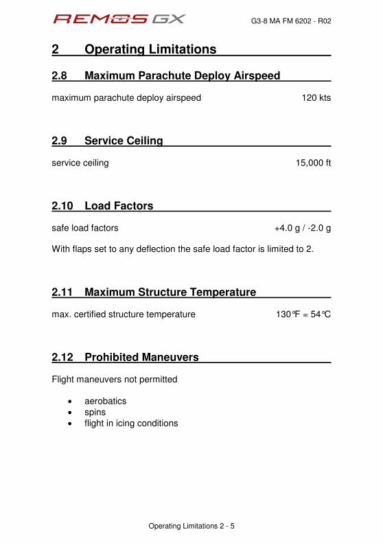
2.8 Maximum Parachute Deploy Airspeed maximum parachute deploy airspeed 120 kts
2.9 Service Ceiling service ceiling 15,000 ft
2.10 Load Factors safe load factors +4.0 g / -2.0 g With flaps set to any deflection the safe load factor is limited to 2.
2.11 Maximum Structure Temperature max. certified structure temperature 130°F = 54°C
2.12 Prohibited Maneuvers Flight maneuvers not permitted
‚ aerobatics
‚ spins
‚ flight in icing conditions

G3-8 MA FM 6202 - R02
2 Operating Limitations
Operating Limitations 2 - 6
2.13 Aproved Flight Maneuvers The following maneuvers are permitted
‚ all non-aerobatic maneuvers, including stalls and departure stalls
‚ flight with the doors off
2.14 Engine manufacturer Bombardier-Rotax
engine type 912 UL-S2 or 912-S2
max. power take-off 73.5 kW / 100 HP max. cont. 69.0 kW / 95 HP
max. engine speed take-off 5,800 rpm
continuous 5,500 rpm
gear ratio 2.43 : 1
slipper clutch optional
coolant BASF Glysantin Protect Plus/G48
coolant or CHT temp min not defined
max 135°C = 275°F 120°C = 248°F with SB-011 complied
mixing ratio 1:1 (Glysantin : water)
NOTE
Please refer to REMOS notification NOT-001 and ROTAX SI-912-016/SI-914-019 for further information on suitable engine fluids (fuel, oil, cooling liquid, additives, etc). Have a frequent look on www.flyrotax.com and on www.remos.com for the latest information.
G3-8 MA FM 6202 - R02
2 Operating Limitations
Operating Limitations 2 - 7
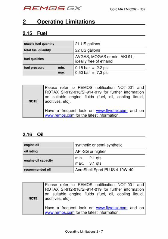
2.15 Fuel
usable fuel quantity 21 US gallons
total fuel quantity 22 US gallons
fuel qualities AVGAS, MOGAS or min. AKI 91, ideally free of ethanol
fuel pressure min. 0,15 bar = 2.2 psi max. 0,50 bar = 7.3 psi
NOTE
Please refer to REMOS notification NOT-001 and ROTAX SI-912-016/SI-914-019 for further information on suitable engine fluids (fuel, oil, cooling liquid, additives, etc). Have a frequent look on www.flyrotax.com and on www.remos.com for the latest information.
2.16 Oil
engine oil synthetic or semi-synthetic
oil rating API-SG or higher
engine oil capacity min. 2.1 qts
max. 3.1 qts
recommended oil AeroShell Sport PLUS 4 10W-40
NOTE
Please refer to REMOS notification NOT-001 and ROTAX SI-912-016/SI-914-019 for further information on suitable engine fluids (fuel, oil, cooling liquid, additives, etc). Have a frequent look on www.flyrotax.com and on www.remos.com for the latest information.
G3-8 MA FM 6202 - R02
2 Operating Limitations
Operating Limitations 2 - 8
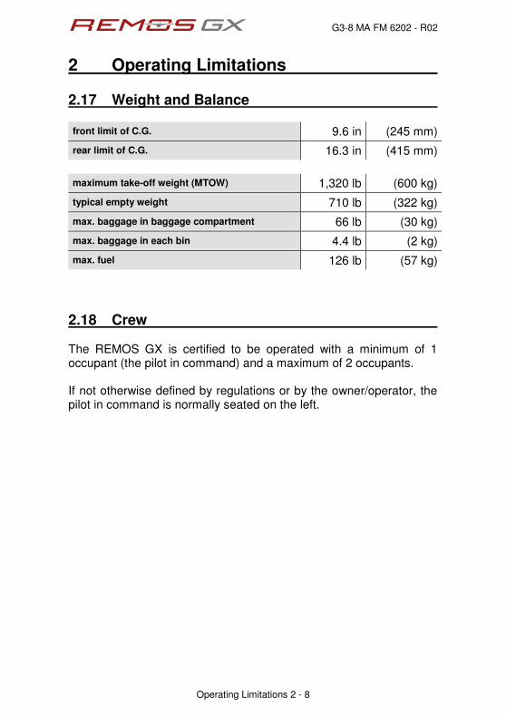
2.17 Weight and Balance
front limit of C.G. 9.6 in (245 mm)
rear limit of C.G. 16.3 in (415 mm)
maximum take-off weight (MTOW) 1,320 lb (600 kg)
typical empty weight 710 lb (322 kg)
max. baggage in baggage compartment 66 lb (30 kg)
max. baggage in each bin 4.4 lb (2 kg)
max. fuel 126 lb (57 kg)
2.18 Crew The REMOS GX is certified to be operated with a minimum of 1 occupant (the pilot in command) and a maximum of 2 occupants. If not otherwise defined by regulations or by the owner/operator, the pilot in command is normally seated on the left.
G3-8 MA FM 6202 - R02
2 Operating Limitations
Operating Limitations 2 - 9
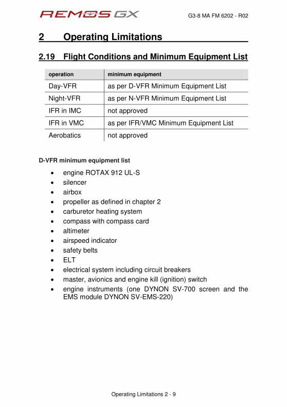
2.19 Flight Conditions and Minimum Equipment List
operation minimum equipment
Day-VFR as per D-VFR Minimum Equipment List
Night-VFR as per N-VFR Minimum Equipment List
IFR in IMC not approved
IFR in VMC as per IFR/VMC Minimum Equipment List
Aerobatics not approved
D-VFR minimum equipment list
‚ engine ROTAX 912 UL-S
‚ silencer
‚ airbox
‚ propeller as defined in chapter 2
‚ carburetor heating system
‚ compass with compass card
‚ altimeter
‚ airspeed indicator
‚ safety belts
‚ ELT
‚ electrical system including circuit breakers
‚ master, avionics and engine kill (ignition) switch
‚ engine instruments (one DYNON SV-700 screen and the EMS module DYNON SV-EMS-220)

G3-8 MA FM 6202 - R02
2 Operating Limitations
Operating Limitations 2 - 10
N-VFR Minimum equipment list
‚ as per D-VFR minimum equipment list, plus
‚ electrical artificial horizon (ADAHRS module DYNON SV-ADAHRS-200)
‚ instrument panel lighting
‚ AeroLEDs SUNTAIL taillight with integrated ACL
‚ AeroLEDs NS90 position lights with integrated ACL
‚ landing light (AeroLEDs AEROSUN 1600 or AeroLEDS AEROSUN X-TREME)
‚ communication radio (e.g. Garmin SL40, Garmin SL30, Garmin GTR225 series or GNC255 series)
‚ transponder (DYNON SV-XPNDR-261)
IFR/VMC Minimum equipment list
‚ as per N-VFR minimum equipment list, plus
‚ navigation radio (e.g. Garmin SL30 or GNC255 series)
‚ audio panel (e.g. Garmin GMA340 or ps-engineering PMA8000BT including marker antennas)


G3-8 MA FM 6202 - R02
2 Operating Limitations
Operating Limitations 2 - 12
2.21 Placards and Markings The required placards and markings are created with the following color codes.
Type
Inside
Outside
Information
white lettering on a black background - white framed
black lettering on a white background - black framed
Safety
white lettering on a black background - red framed
red lettering on a white background - red framed
Warning
white lettering on a red background - white framed
red lettering on a white background - red framed


G3-8 MA FM 6202 - R02
2 Operating Limitations
Operating Limitations 2 - 14
placards location
center console
right rocker
panel
baggage
compartment

G3-8 MA FM 6202 - R02
2 Operating Limitations
Operating Limitations 2 - 15
The following safety placards are mandatory. They are located on the instrument panel. The list below does not define the layout but the content and intent of the placards. placard location
right
cockpit
The following safety placard is located on the left side of the panel. This placard is mandatory. placard location
left cockpit
G3-8 MA FM 6202 - R02
2 Operating Limitations
Operating Limitations 2 - 16
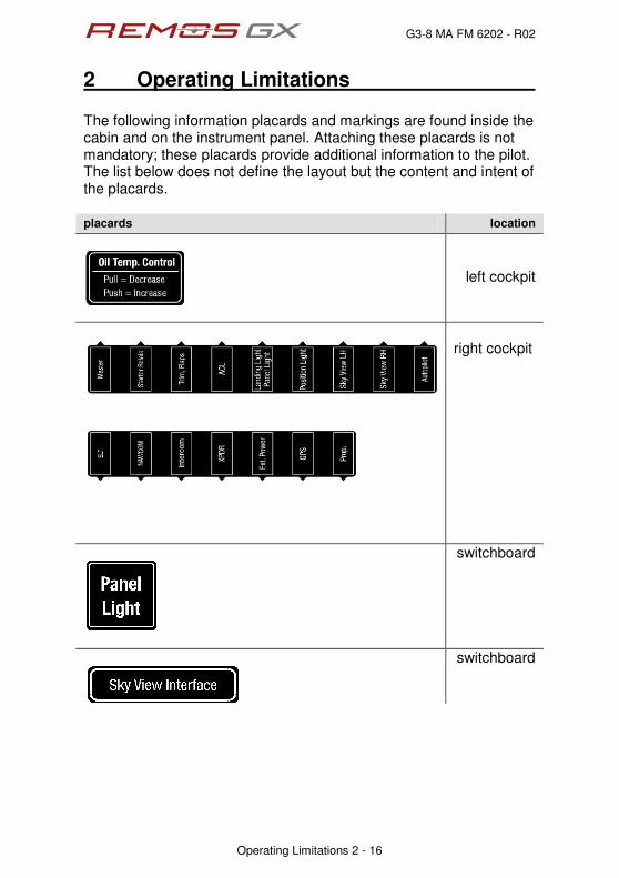
The following information placards and markings are found inside the cabin and on the instrument panel. Attaching these placards is not mandatory; these placards provide additional information to the pilot. The list below does not define the layout but the content and intent of the placards. placards location
left cockpit
right cockpit
switchboard
switchboard

G3-8 MA FM 6202 - R02
2 Operating Limitations
Operating Limitations 2 - 17
placards location
center
console
center
console
switchboard
switchboard

G3-8 MA FM 6202 - R02
2 Operating Limitations
Operating Limitations 2 - 18
placards location
switchboard
switchboard
switchboard
switchboard
optional: constant speed prop
switchboard

G3-8 MA FM 6202 - R02
2 Operating Limitations
Operating Limitations 2 - 19
The following information placards and markings are found outside the cabin. Attaching these placards is not mandatory; these placards provide additional information to the pilot. The list below does not define the layout but the content and intent of the placards. placards location
fuel tank filler cap
wheel fairings
static port

G3-8 MA FM 6202 - R02
2 Operating Limitations
Operating Limitations 2 - 20
The following safety placards and markings are found inside the cabin. Attaching these placards is not mandatory; these placards provide additional information to the pilot. The list below does not define the layout but the content and intent of the placards. placards location
center stack
aileron pushrod
cabin side at aileron
pushrod cut out
baggage
compartment
baggage
compartment
fuel tank sight hose

G3-8 MA FM 6202 - R02
2 Operating Limitations
Operating Limitations 2 - 21
The following safety placards and markings are found outside the cabin. Attaching these placards is not mandatory; these placards provide additional information to the pilot. The list below does not define the layout but the content and intent of the placards. placards location
center of elevator
next to the opening for aileron pushrod,
covered by wing if not folded
center of fixed
surface of elevator, covered if elevator
is installed
wing main bolt
wing

G3-8 MA FM 6202 - R02
2 Operating Limitations
Operating Limitations 2 - 22
placards location
strut
G3-8 MA FM 6202 - R02
2 Operating Limitations
Operating Limitations 2 - 23
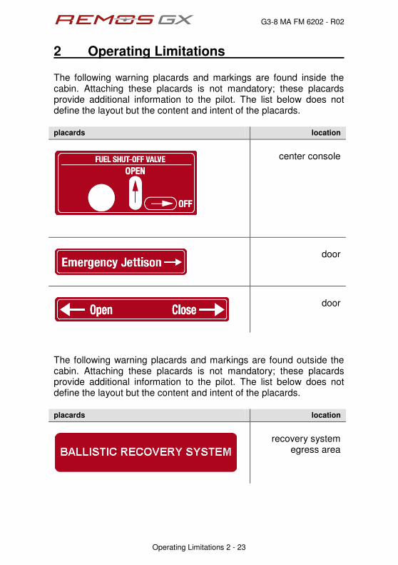
The following warning placards and markings are found inside the cabin. Attaching these placards is not mandatory; these placards provide additional information to the pilot. The list below does not define the layout but the content and intent of the placards. placards location
center console
door
door
The following warning placards and markings are found outside the cabin. Attaching these placards is not mandatory; these placards provide additional information to the pilot. The list below does not define the layout but the content and intent of the placards. placards location
recovery system
egress area

G3-8 MA FM 1203 - R06
3 Emergency Procedures
Emergency Procedures 3 - 1
Table of Content
sect. description page
3.1 Definitions 3-2
3.2 Jettison of Doors 3-3
3.3 Spin Recovery 3-3
3.4 Recovery System 3-3
3.5 Emergency Descent 3-3
3.6 Carburetor Icing 3-4
3.7 Inadvertent Icing Encounter 3-4
3.8 Overvoltage 3-4
3.9 Alternator Failure 3-5
3.10 Voltage Drop 3-5
3.11 Loss of Altimeter 3-6
3.12 Loss of Airspeed Indicator 3-7
3.13 Loss of Elevator Control 3-8
3.14 Loss of Aileron Control 3-9
3.15 Loss of Rudder Control 3-10
3.16 Loss of Trim System 3-11
3.17 Loss of Flap Control System 3-12
3.18 Loss of Oil Pressure 3-13
3.19 High Oil Pressure 3-14
3.20 High Cylinder Head Temperature 3-15
3.21 Engine Stoppage during Take-Off 3-16
3.22 Engine Stoppage in Flight 3-17
3.23 Engine on Fire During Start-Up 3-17
3.24 Engine on Fire During Take-Off 3-18
3.25 Engine on Fire in Flight 3-19
3.26 Precautionary Landing 3-20
3.27 Emergency Landing on Land 3-21
3.28 Emergency Landing on Water 3-22

G3-8 MA FM 1203 - R06
3 Emergency Procedures
Emergency Procedures 3 - 2
3.1 Definitions
Procedures
are instructions that must be performed in the given sequence, as far as possible without interruption.
Checklists
are lists for items to be checked in the applicable phase of flight (taxi, take-off, climb, etc.). Timing and sequence of the steps to be executed may vary according to the individual flight.
Briefings
are guidelines for upcoming procedures. With the help of briefings, the pilot and passenger should recapitulate those procedures.

G3-8 MA FM 1203 - R06
3 Emergency Procedures
Emergency Procedures 3 - 3
3.2 Jettison of Doors Procedure
1. door lock OPEN
2. hinge pin PULL
3. door JETTISON
3.3 Spin Recovery Procedure
1. control stick NEUTRAL
2. rudder OPPOSITE SPIN DIRECTION
3. after stopping of rotation RECOVER
3.4 Recovery System Procedure
1. engine STOP
2. recovery system RELEASE
3. fuel valve CLOSE
4. declare emergency MAYDAY MAYDAY MAYDAY
5. master switch OFF
6. safety belts TIGHTEN
3.5 Emergency Descent Procedure
1. engine IDLE
2. flaps UP
3. carburetor heat PULL
4. electric fuel pump ON
5. airspeed in rough air 107 kIAS = 123 mph IAS
airspeed in calm air 134 kIAS = 155 mph IAS

G3-8 MA FM 1203 - R06
3 Emergency Procedures
Emergency Procedures 3 - 4
3.6 Carburetor Icing Procedure
1. carburetor heat PULL
2. electric fuel pump ON
3. power setting FULL POWER
3.7 Inadvertent Icing Encounter Procedure
1. engine FULL POWER
2. flaps UP
3. carburetor heat PULL
4. electric fuel pump ON
5. heading change BACKTRACK
6. descent LEAVING ICING CONDITIONS
7. altitude KEEP SAFE ALTITUDE
3.8 Overvoltage Procedure
1. overvoltage IDENTIFY VOLTAGE > 15V
2. master switch OFF
3. land on appropriate airfield
G3-8 MA FM 1203 - R06
3 Emergency Procedures
Emergency Procedures 3 - 5
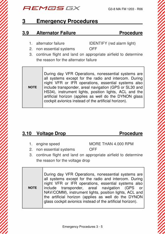
3.9 Alternator Failure Procedure
1. alternator failure IDENTIFY (red alarm light)
2. non essential systems OFF
3. continue flight and land on appropriate airfield to determine
the reason for the alternator failure
NOTE
During day VFR Operations, nonessential systems are all systems except for the radio and intercom. During night VFR or IFR operations, essential systems also include transponder, areal navigation (GPS or SL30 and HS34), instrument lights, position lights, ACL and the artificial horizon (applies as well do the DYNON glass cockpit avionics instead of the artificial horizon).
3.10 Voltage Drop Procedure
1. engine speed MORE THAN 4.000 RPM
2. non essential systems OFF
3. continue flight and land on appropriate airfield to determine
the reason for the voltage drop
NOTE
During day VFR Operations, nonessential systems are all systems except for the radio and intercom. During night VFR or IFR operations, essential systems also include transponder, areal navigation (GPS or NAV/COMM), instrument lights, position lights, ACL and the artificial horizon (applies as well do the DYNON glass cockpit avionics instead of the artificial horizon).

G3-8 MA FM 1203 - R06
3 Emergency Procedures
Emergency Procedures 3 - 6
3.11 Loss of Altimeter Procedure
for aircraft with more than one altimeter installed
1. AVIATE Î NAVIGATE Î COMMUNICATE
2. altimeter USE ALTERNATE ALTIMETER
3. in case of failure of all altimeters installed continue with
procedure below
aircraft with just one altimeter and within airspace requiring clearance
1. radio communication INFORM ATC
2. instructions by ATC ACT ACCORDINGLY
3. continue flight and land on appropriate airfield to determine
the reason for the altimeter failure
aircraft with just one altimeter but outside airspace requiring clearance
1. altitude KEEP SAFE ALTITUDE
2. instructions by ATC ACT ACCORDINGLY
3. continue flight and land on appropriate airfield to determine
the reason for the altimeter failure

G3-8 MA FM 1203 - R06
3 Emergency Procedures
Emergency Procedures 3 - 7
3.12 Loss of Airspeed Indicator Procedure
for aircraft with more than one airspeed indicator installed
1. AVIATE Î NAVIGATE Î COMMUNICATE
2. airspeed indicator USE ALTERNATE ASI
3. in case of failure of all airspeed indicators installed continue
with procedure below
for aircraft with one airspeed indicator installed or total failure of ASI
1. engine speed in cruise 60422È4.600 rpm
landing without airspeed indicator
1. airfield APPROPRIATE RWY LENGTH
2. flaps UP
3. carburetor heat PULL
4. electric fuel pump ON
5. engine speed in decent 40722È3.000 rpm
6. pitch KEEP WITHIN estd. +/-10 deg
7. short final approach POWER IDLE
8. flare AS APPROPRIATE
9. touch down on main wheels first with very little flare.
10. brakes IMMEDIATELY
NOTE
Landing distance with this procedure is significantly longer than a standard landing. Expect distances far in excess of 2.000 ft / 600m or even more. Select an airfield with sufficient runway length available.

G3-8 MA FM 1203 - R06
3 Emergency Procedures
Emergency Procedures 3 - 8
3.13 Loss of Elevator Control Procedure
aircraft equipped with recovery system
1. AVIATE Î NAVIGATE Î COMMUNICATE
2. declare emergency MAYDAY MAYDAY MAYDAY
3. recovery system DEPLOY
aircraft without recovery system
1. AVIATE Î NAVIGATE Î COMMUNICATE
2. declare emergency MAYDAY MAYDAY MAYDAY
3. power setting FOR LEVEL FLIGHT
4. elevator control USE TRIM SYSTEM
5. landing EMERGENCY LANDING
NOTE
With a failed elevator control the aircraft might be controlled with the trim system. Pitch control is extremely limited. Engine power control might support pitch control.
NOTE
stuck/blocked elevator control
UP trim will result in a nose down response DOWN trim will result in a nose up response disconnected/floating elevator control
UP trim will result in a nose up response DOWN trim will result in a nose down response
WARNING
Loss of elevator control is an extremely severe situation that might result in loss of control of the aircraft, serious injuries or even death.

G3-8 MA FM 1203 - R06
3 Emergency Procedures
Emergency Procedures 3 - 9
3.14 Loss of Aileron Control Procedure
aircraft equipped with recovery system
1. AVIATE Î NAVIGATE Î COMMUNICATE
2. declare emergency MAYDAY MAYDAY MAYDAY
3. recovery system DEPLOY
aircraft without recovery system
1. AVIATE Î NAVIGATE Î COMMUNICATE
2. declare emergency MAYDAY MAYDAY MAYDAY
3. power setting FOR LEVEL FLIGHT
4. control USE RUDDER CONTROL
5. landing EMERGENCY LANDING
NOTE
With a failed aileron control the aircraft might be controlled with the rudder control resulting in excessive sideslip conditions.
WARNING
Loss of aileron control is an extremely severe situation that might result in loss of control of the aircraft, serious injuries or even death.
G3-8 MA FM 1203 - R06
3 Emergency Procedures
Emergency Procedures 3 - 10
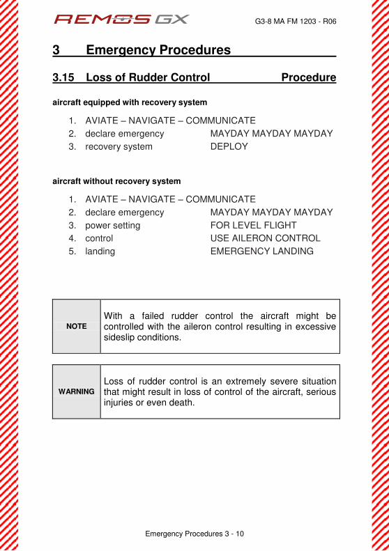
3.15 Loss of Rudder Control Procedure
aircraft equipped with recovery system
1. AVIATE Î NAVIGATE Î COMMUNICATE
2. declare emergency MAYDAY MAYDAY MAYDAY
3. recovery system DEPLOY
aircraft without recovery system
1. AVIATE Î NAVIGATE Î COMMUNICATE
2. declare emergency MAYDAY MAYDAY MAYDAY
3. power setting FOR LEVEL FLIGHT
4. control USE AILERON CONTROL
5. landing EMERGENCY LANDING
NOTE
With a failed rudder control the aircraft might be controlled with the aileron control resulting in excessive sideslip conditions.
WARNING
Loss of rudder control is an extremely severe situation that might result in loss of control of the aircraft, serious injuries or even death.

G3-8 MA FM 1203 - R06
3 Emergency Procedures
Emergency Procedures 3 - 11
3.16 Loss of Trim System Procedure
pitch down trim runaway or stuck trim with lot of trim down
1. AVIATE Î NAVIGATE Î COMMUNICATE
2. expect nose down attitude
3. keep nose up with manual stick input
4. release trim circuit breaker
5. expect higher stick forces than usual
6. continue flight and land on appropriate airfield to determine
the reason for the trim system failure
pitch up trim runaway or stuck trim with lot of trim up
1. AVIATE Î NAVIGATE Î COMMUNICATE
2. expect nose up attitude
3. keep nose level with manual stick input
4. release trim circuit breaker
5. expect higher stick forces than usual
6. continue flight and land on appropriate airfield to determine
the reason for the trim system failure
NOTE
The aircraft is controllable even with a complete trim runaway. Keep your airspeed below VNO to keep stick forces within reasonable limits.

G3-8 MA FM 1203 - R06
3 Emergency Procedures
Emergency Procedures 3 - 12
3.17 Loss of Flaps Control System Procedure
flaps stuck in deflected position or flaps down runaway
1. AVIATE Î NAVIGATE Î COMMUNICATE
2. max. flap speed VFE = 78 kIAS = 90 mph IAS
3. approach airspeed VAPP = 60 kIAS = 69 mph IAS
4. return to airfield or continue flight and land on appropriate
airfield to determine the reason of the failure
flaps stuck in retracted position or flaps up runaway
1. AVIATE Î NAVIGATE Î COMMUNICATE
2. stall speed VS1 = 44 kIAS = 51 mph IAS
3. approach airspeed VAPP = 60 kIAS = 69 mph IAS
4. return to airfield or continue flight and land on appropriate
airfield to determine the reason of the failure
NOTE
Keep in mind that landing distances presented in section 5 of this POH are applicable to the normal landing procedure. Landing with flaps up will result in longer landing distances.

G3-8 MA FM 1203 - R06
3 Emergency Procedures
Emergency Procedures 3 - 13
3.18 Loss of Oil Pressure Procedure
oil temperature not stable (constantly and rapidly rising)
smell of oil, oil fumes, oil on windscreen
5. AVIATE Î NAVIGATE Î COMMUNICATE
6. PERFORM PRECAUTIONARY LANDING
oil temperature stable (constant oil temperature)
no obvious oil leakage, engine running smooth
1. monitor oil temperature STABLE
2. CHT max. 275°F = 135°C
3. oil temperature 342È488̇H"?"72È352̇E
4. continue flight and land on appropriate airfield to determine
the reason for the indicated oil pressure loss
WARNING
Loss of oil pressure may be a result of an oil leakage. This is an extremely dangerous situation as is implies the immediate danger of an in-flight fire. Be sensitive to any kind of abnormal smell or fire. Be prepared for an immediate precautionary landing, maybe emergency landing!
G3-8 MA FM 1203 - R06
3 Emergency Procedures
Emergency Procedures 3 - 14
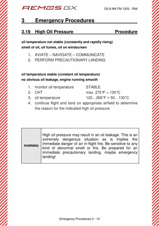
3.19 High Oil Pressure Procedure
oil temperature not stable (constantly and rapidly rising)
smell of oil, oil fumes, oil on windscreen
1. AVIATE Î NAVIGATE Î COMMUNICATE
2. PERFORM PRECAUTIONARY LANDING
oil temperature stable (constant oil temperature)
no obvious oil leakage, engine running smooth
1. monitor oil temperature STABLE
2. CHT max. 275°F = 135°C
3. oil temperature 342È488̇H"?"72È352̇E
4. continue flight and land on appropriate airfield to determine
the reason for the indicated high oil pressure
WARNING
High oil pressure may result in an oil leakage. This is an extremely dangerous situation as is implies the immediate danger of an in-flight fire. Be sensitive to any kind of abnormal smell or fire. Be prepared for an immediate precautionary landing, maybe emergency landing!
G3-8 MA FM 1203 - R06
3 Emergency Procedures
Emergency Procedures 3 - 15
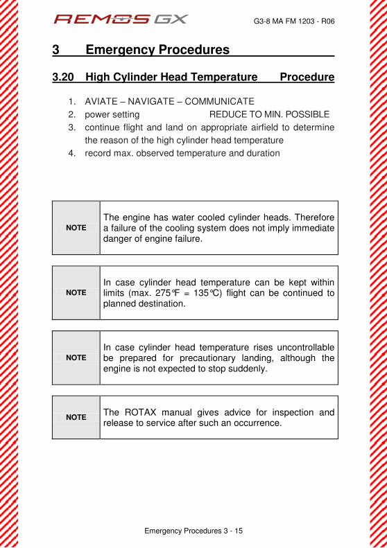
3.20 High Cylinder Head Temperature Procedure
1. AVIATE Î NAVIGATE Î COMMUNICATE
2. power setting REDUCE TO MIN. POSSIBLE
3. continue flight and land on appropriate airfield to determine
the reason of the high cylinder head temperature
4. record max. observed temperature and duration
NOTE
The engine has water cooled cylinder heads. Therefore a failure of the cooling system does not imply immediate danger of engine failure.
NOTE
In case cylinder head temperature can be kept within limits (max. 275°F = 135°C) flight can be continued to planned destination.
NOTE
In case cylinder head temperature rises uncontrollable be prepared for precautionary landing, although the engine is not expected to stop suddenly.
NOTE
The ROTAX manual gives advice for inspection and release to service after such an occurrence.
G3-8 MA FM 1203 - R06
3 Emergency Procedures
Emergency Procedures 3 - 16
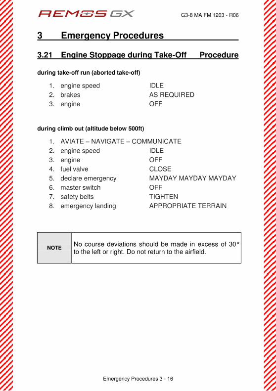
3.21 Engine Stoppage during Take-Off Procedure
during take-off run (aborted take-off)
1. engine speed IDLE
2. brakes AS REQUIRED
3. engine OFF
during climb out (altitude below 500ft)
1. AVIATE Î NAVIGATE Î COMMUNICATE
2. engine speed IDLE
3. engine OFF
4. fuel valve CLOSE
5. declare emergency MAYDAY MAYDAY MAYDAY
6. master switch OFF
7. safety belts TIGHTEN
8. emergency landing APPROPRIATE TERRAIN
NOTE
No course deviations should be made in excess of 30° to the left or right. Do not return to the airfield.

G3-8 MA FM 1203 - R06
3 Emergency Procedures
Emergency Procedures 3 - 17
3.22 Engine Stoppage in Flight Procedure
case 1: altitude not enough for engine re-start
1. AVIATE Î NAVIGATE Î COMMUNICATE
2. landing site IDENTIFY
3. engine OFF
4. fuel valve CLOSE
5. declare emergency MAYDAY MAYDAY MAYDAY
6. master switch OFF
7. safety belts TIGHTEN
8. emergency landing APPROPRIATE TERRAIN
case 2: altitude sufficient for engine re-start
1. AVIATE Î NAVIGATE Î COMMUNICATE
2. landing site IDENTIFY
3. carburetor heat PULL
4. electric fuel pump ON
5. choke OFF
6. starter ENGAGE
7. if engine does not start continue with case 1
8. if engine starts, continue flight and land on appropriate
airfield to determine the reason for engine failure
3.23 Engine on Fire During Start-Up Procedure
1. fuel valve CLOSE
2. carburetor heat PULL
3. electric fuel pump OFF
4. power setting FULL until ENGINE STOPS
5. master switch OFF
6. if fire does not extinguish VACATE IMMEDIATELY

G3-8 MA FM 1203 - R06
3 Emergency Procedures
Emergency Procedures 3 - 18
3.24 Engine on Fire During Take-Off Procedure
during take-off run (aborted take-off)
1. engine speed IDLE
2. brakes FULL and SET
3. fuel valve CLOSE
4. carburetor heat PULL
5. electric fuel pump OFF
6. power setting FULL until ENGINE STOPS
7. master switch OFF
8. if fire does not extinguish VACATE IMMEDIATELY
during climb out (altitude below 500ft)
1. AVIATE Î NAVIGATE Î COMMUNICATE
2. engine speed IDLE
3. engine OFF
4. fuel valve CLOSE
5. carburetor heat PULL
6. declare emergency MAYDAY MAYDAY MAYDAY
7. master switch OFF
8. safety belts TIGHTEN
9. emergency landing APPROPRIATE TERRAIN
NOTE
No course deviations should be made in excess of 30° to the left or right. Do not return to the airfield.
WARNING
Never release the recovery system in case of fire.

G3-8 MA FM 1203 - R06
3 Emergency Procedures
Emergency Procedures 3 - 19
3.25 Engine on Fire in Flight Procedure
1. AVIATE Î NAVIGATE Î COMMUNICATE
2. landing site IDENTIFY
3. fuel valve CLOSE
4. carburetor heat PULL
5. electric fuel pump OFF
6. power setting FULL until ENGINE STOPS
7. declare emergency MAYDAY MAYDAY MAYDAY
8. master switch OFF
9. descent EMERGENCY DECENT
10. slip AS REQUIRED
11. safety belts TIGHTEN
12. emergency landing APPROPRIATE TERRAIN
WARNING
Never release the recovery system in case of fire.

G3-8 MA FM 1203 - R06
3 Emergency Procedures
Emergency Procedures 3 - 20
3.26 Precautionary Landing Procedure
1. AVIATE Î NAVIGATE Î COMMUNICATE
2. landing site IDENTIFY
3. direction of wind IDENTIFY
4. landing direction INTO THE WIND or UPHILL
5. landing site inspection PERFORM LOW APPROACH
6. approach airspeed VAPP = 60 kIAS = 69 mph IAS
7. max. flap speed VFE = 78 kIAS = 90 mph IAS
8. declare emergency OWN DISCRETION
9. safety belts TIGHTEN
10. flaps DOWN
11. landing light RECOMMENDED
12. engine power AS REQUIRED
13. elevator trim AS REQUIRED
14. electric fuel pump ON
15. carburetor heat RECOMMENDED
16. oil cooler flap AS REQUIRED
17. CHT max. 275°F = 135°C
18. oil temperature 342È488̇H"?"72È352̇E
19. touch down on main wheels first with very little flare.
20. brakes IMMEDIATELY
21. avionics switch OFF
22. landing light OFF
23. position lights OFF
24. engine OFF
25. ACL OFF
26. cockpit lights OFF
27. master switch OFF
28. recovery system SECURED
29. parking brake SET

G3-8 MA FM 1203 - R06
3 Emergency Procedures
Emergency Procedures 3 - 21
3.27 Emergency Landing on Land Procedure
1. AVIATE Î NAVIGATE Î COMMUNICATE
2. landing site IDENTIFY
3. direction of wind IDENTIFY
4. approach airspeed VAPP = 60 kIAS = 69 mph IAS
5. max. flap speed VFE = 78 kIAS = 90 mph IAS
6. flaps DOWN
7. trim AS REQUIRED
8. declare emergency MAYDAY MAYDAY MAYDAY
9. master switch OFF
10. safety belts TIGHTEN
11. landing direction INTO THE WIND
or UPHILL
12. touchdown with full elevator on main wheels first
13. after landing, release safety belts and vacate aircraft
G3-8 MA FM 1203 - R06
3 Emergency Procedures
Emergency Procedures 3 - 22
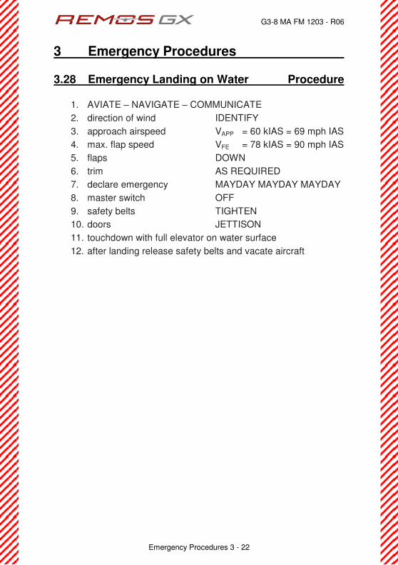
3.28 Emergency Landing on Water Procedure
1. AVIATE Î NAVIGATE Î COMMUNICATE
2. direction of wind IDENTIFY
3. approach airspeed VAPP = 60 kIAS = 69 mph IAS
4. max. flap speed VFE = 78 kIAS = 90 mph IAS
5. flaps DOWN
6. trim AS REQUIRED
7. declare emergency MAYDAY MAYDAY MAYDAY
8. master switch OFF
9. safety belts TIGHTEN
10. doors JETTISON
11. touchdown with full elevator on water surface
12. after landing release safety belts and vacate aircraft
G3-8 MA FM 1204 - R06
4 Normal Procedures
Normal Procedures 4 - 1
Table of Content
sect. description page
4.1 Definitions 4-2
4.2 Fuel Draining 4-3
4.3 Preflight Check 4-4
4.4 Before Start-Up 4-7
4.5 Engine Start 4-7
4.6 After Start-Up 4-8
4.7 Engine Run Up 4-8
4.8 Taxi 4-9
4.9 Departure 4-9
4.10 Take-Off 4-10
4.11 Best Angle of Climb Speed (VX) 4-13
4.12 Best Rate of Climb Speed (VY) 4-13
4.13 Cruise 4-14
4.14 Flying in Rain 4-15
4.15 Flying Without Doors 4-16
4.16 Recovery from Stall 4-17
4.17 Descent 4-17
4.18 Approach 4-18
4.19 Landing 4-19
4.20 Balked Landing 4-22
4.21 After Landing 4-22
4.22 Shutdown 4-23
G3-8 MA FM 1204 - R06
4 Normal Procedures
Normal Procedures 4 - 2
4.1 Definitions
Procedures
are instructions that must be performed in the given sequence, as far as possible without interruption.
Checklists
are lists for items to be checked in the apropriate phase of flight (taxi, take-off, climb, etc.). Timing and sequence of the steps to be executed may vary according to the individual flight.
Briefings
are guidelines for upcoming procedures. With the help of briefings, the pilot and passenger should recapitulate those procedures.

G3-8 MA FM 1204 - R06
4 Normal Procedures
Normal Procedures 4 - 3
4.2 Fuel Draining Procedure Since auto fuel contains a significant amount of ethanol nowadays, draining of the fuel system is more and more important. Draining of the aircraft must be performed before moving the aircraft at all. After re-fueling the aircraft, draining is also required. Give the fuel several minutes to rest after filling it up and do not move the aircraft prior to draining. The drainer is located underneath the belly, just behind the main landing gear. From the outside only a plastic hose with 0.5 in diameter is visible. To drain the fuel tank, press on the plastic hose. Capture the released fuel and analyze it for water. If AVGAS or MOGAS is used, water will clearly deposit underneath the fuel. Continue draining until no more water can be detected. In the case of auto fuel containing ethanol, water can be absorbed by the fuel up to a certain amount, so no water will be detected during draining. If the fuel looks like a milky dispersion, the fuel is saturated with water. In this case dump all of the fuel, do not use this fuel for flying! After dumping fuel, fill up the fuel tank completely with fuel without ethanol. To dump fuel, press in the plastic drainer hose and turn it counter-clockwise (as seen from bottom) about ¼ of a turn. To close the drainer, turn the plastic hose back. Be sure the drainer is properly closed. If dust or dirt particles get inside the drainer, the drainer will not close properly. In this case, open the drainer again to clean the drainer. When draining the aircraft take care that no fuel contaminates the environment. Dispose of drained or dumped fuel in an environmental correct manner. For further information about fuel containing ethanol please refer to the REMOS Notification NOT-001-ethanol-fuel.

G3-8 MA FM 1204 - R06
4 Normal Procedures
Normal Procedures 4 - 4
4.3 Preflight Check Checklist
Checks outside the aircraft
1. fuel system drained before moving the aircraft at all
2. engine oil level (between min. and max. markings)
3. level of engine coolant (between min. and max. markings)
4. cowling is closed and properly secured
5. propeller has no damage or wear
6. nose gear and wheel/tire have no damage or wear, air pressure is
correct and suspension is free
7. static port is clean
8. main wing bolt properly secured with Fokker needle
9. pitot tube is clean and properly fixed
10. wingtip and cover glass are securely mounted and not damaged
11. aileron, linkage and hinges have free travel and no damage,
counterweights are securely fixed
12. upper wing strut attachment is secured
13. flap, linkage and hinges have no damage, rubber stops (flutter
damper) on outer hinges are in place
14. lower wing strut attachment is secured
15. belly top antennas are securely mounted and free of damage
16. left main gear and wheel/tire have no damage or wear, air pressure
is correct and suspension is free
17. cover of ejection opening has no damage
18. top antennas are securely mounted and free of damage
19. fuselage has no damage
20. horizontal tail, elevator, linkage and hinges have free travel and no
damage
21. trim actuator linkage securely mounted and not damaged
22. elevator quick-fastener is securely locked
23. rudder linkage and hinges have free travel and no damage
24. horizontal tail attachment bolts are secured
25. horizontal tail, elevator, linkage and hinges have free travel and no
damage

G3-8 MA FM 1204 - R06
4 Normal Procedures
Normal Procedures 4 - 5
26. fuselage has no damage
27. right main gear and wheel/tire have no damage or wear, air pressure
is correct and suspension is free
28. lower wing strut attachment is secured
29. flap, linkage and hinges have no damage, rubber stops (flutter
damper) on outer hinges are in place
30. upper wing strut attachment is secured
31. aileron, linkage and hinges have free travel and no damage ,
counterweights are securely fixed
32. wingtip and cover glass are securely mounted and not damaged
33. landing light glass is not damaged
34. static port is clean
35. main wing bolt properly secured with Fokker needle It is suggested to perform the outside check according to the following flow diagram:
Insecurely connected, improper operation of control surfaces or insecurely locked fasteners will lead to loss of control of the aircraft!!
1
9
11
12
13
14,15,16
17,18,19
2,3,4,5,6
10
22,23 24,25 20,21
26
27,28
29
30
31
32 33
34,35 7,8
G3-8 MA FM 1204 - R06
4 Normal Procedures
Normal Procedures 4 - 6
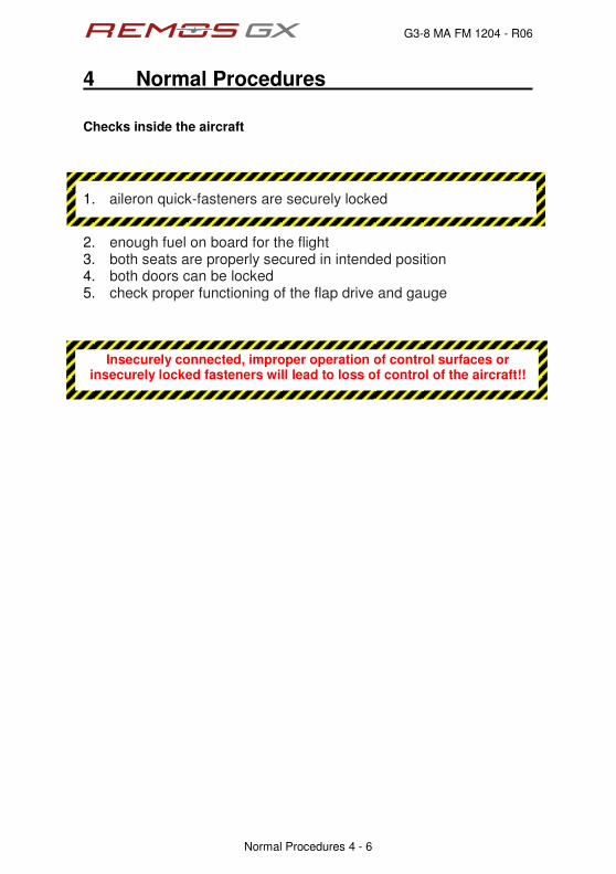
Checks inside the aircraft
1. aileron quick-fasteners are securely locked
2. enough fuel on board for the flight 3. both seats are properly secured in intended position 4. both doors can be locked 5. check proper functioning of the flap drive and gauge
Insecurely connected, improper operation of control surfaces or insecurely locked fasteners will lead to loss of control of the aircraft!!
G3-8 MA FM 1204 - R06
4 Normal Procedures
Normal Procedures 4 - 7
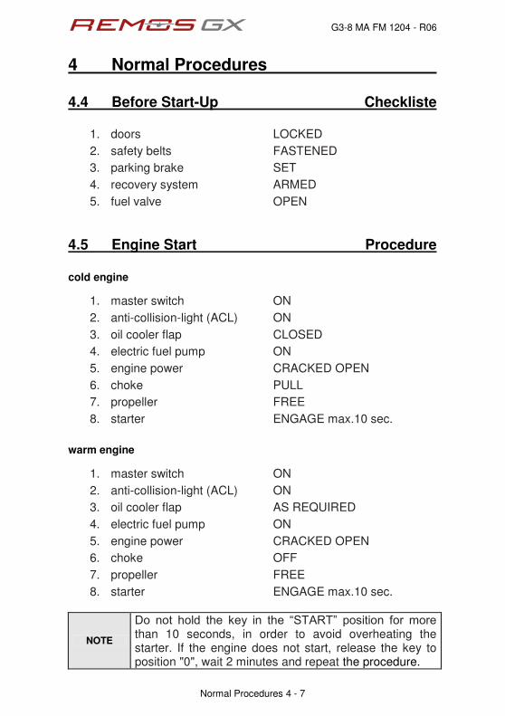
4.4 Before Start-Up Checkliste
1. doors LOCKED
2. safety belts FASTENED
3. parking brake SET
4. recovery system ARMED
5. fuel valve OPEN
4.5 Engine Start Procedure
cold engine
1. master switch ON
2. anti-collision-light (ACL) ON
3. oil cooler flap CLOSED
4. electric fuel pump ON
5. engine power CRACKED OPEN
6. choke PULL
7. propeller FREE
8. starter ENGAGE max.10 sec.
warm engine
1. master switch ON
2. anti-collision-light (ACL) ON
3. oil cooler flap AS REQUIRED
4. electric fuel pump ON
5. engine power CRACKED OPEN
6. choke OFF
7. propeller FREE
8. starter ENGAGE max.10 sec.
NOTE
Fq" pqv" jqnf" vjg" mg{" kp" vjg" ÐUVCTVÑ" rqukvkqp" hqt" oqtg"than 10 seconds, in order to avoid overheating the starter. If the engine does not start, release the key to position "0", wait 2 minutes and repeat the procedure.

G3-8 MA FM 1204 - R06
4 Normal Procedures
Normal Procedures 4 - 8
4.6 After Start-Up Procedure
1. engine has started STARTER DISENGAGE
2. choke OFF
3. oil pressure OK
4. position-lights ON
5. avionics switch ON
6. intercom ON
7. radios ON and FREQUENCY SET
8. transponder AS REQUIRED
9. electric fuel pump OFF
10. engine speed for warm-up 2,500 rpm
NOTE
By having the electric fuel pump switched off after starting the engine, only the mechanical pump is providing the engine with fuel. Make sure that the engine is running without the electric pump for at least two minutes. In that time, the engine burns all fuel in the fuel system behind the mechanical fuel pump. If the engine keeps running, the mechanical fuel pump is operational.
4.7 Engine Run Up Checklist
1. oil temperature min. 50°C / 120°F
2. engine speed 4,000 rpm
3. magneto check max. 300 rpm DROP
4. carburetor heat TEMPERATURE RISES
5. engine speed IDLE
6. electric fuel pump ON
G3-8 MA FM 1204 - R06
4 Normal Procedures
Normal Procedures 4 - 9
4.8 Taxi Procedure
1. landing light RECOMMENDED
2. parking brake RELEASE
3. engine speed AS REQUIRED
4. control on ground VIA PEDALS
5. min. turn radius ca. 20 ft = 7 m
6. braking AS REQUIRED
7. taxi speed APPROPRIATE
4.9 Departure Briefing
1. wind, weather, visibility OK
2. ATIS CHECKED
3. runway CORRECT DIRECTION
4. traffic pattern ALTITUDE and ROUTING
G3-8 MA FM 1204 - R06
4 Normal Procedures
Normal Procedures 4 - 10
4.10 Take-Off Procedure
standard take-off
1. oil cooler flap AS REQUIRED
2. carburetor heat OFF
3. electric fuel pump ON
4. flaps 15 deg
5. elevator trim 2/3 UP
6. rudder and aileron NEUTRAL
7. engine power FULL POWER
8. rotate VR = 45 kIAS = 52 mph IAS
9. lift-off VLO = 50 kIAS = 58 mph IAS
10. steepest climb VX Flaps 15 = 39 kIAS = 45 mph IAS
11. best climb VY Flaps 15 = 58 kIAS = 67 mph IAS
12. retract flaps SAFE ALTITUDE
13. best climb VY clean = 60 kIAS = 69 mph IAS
NOTE
Take-off distances given in chapter 5 have been determined with this procedure. Take-off distance varies significantly with precise handling and condition of the runway.
NOTE It is recommended to keep the electric fuel pump switched on during the entire flight.
NOTE
Take-off with reduced power is possible, though not recommended. No take-off shall be performed with engine speed lower than 4,000 rpm. A drastically reduced take-off performance must be taken into account.
NOTE
Take-off with flaps retracted is possible and permitted. Take-off distance is longer as the aircraft needs further acceleration until lift-off due to higher stall speed.
G3-8 MA FM 1204 - R06
4 Normal Procedures
Normal Procedures 4 - 11
short field take-off
1. oil cooler flap AS REQUIRED
2. carburetor heat OFF
3. electric fuel pump ON
4. brakes SET
5. flaps 15 deg
6. elevator trim 2/3 UP
7. rudder and aileron NEUTRAL
8. engine power FULL POWER
9. brakes RELEASE
10. rotate and lift-off VX Flaps 15 = 39 kIAS = 45 mph IAS
11. steepest climb VX Flaps 15 = 39 kIAS = 45 mph IAS
12. best climb VY Flaps 15 = 58 kIAS = 67 mph IAS
13. retract flaps SAFE ALTITUDE
14. best climb VY clean = 60 kIAS = 69 mph IAS
NOTE
Take-off distances given in chapter 5 have not been determined with this procedure, but with the procedure for standard take-off. Take-off distance with the short field technique varies significantly with precise handling and condition of the runway.
NOTE Take care not to stall the aircraft during this maneuver.
NOTE It is recommended to keep the electric fuel pump switched on during the entire flight.
G3-8 MA FM 1204 - R06
4 Normal Procedures
Normal Procedures 4 - 12
soft field take-off
15. oil cooler flap AS REQUIRED
16. carburetor heat OFF
17. electric fuel pump ON
18. brakes SET
19. flaps 15 deg
20. elevator trim 2/3 UP
21. rudder and aileron NEUTRAL
22. engine power FULL POWER
23. brakes RELEASE
24. rotate IMMEDIATELY
25. lift-off VLO = 35 kIAS = 40 mph IAS
26. accelerate IN GROUND EFFECT
27. steepest climb VX Flaps 15 = 39 kIAS = 45 mph IAS
28. best climb VY Flaps 15 = 58 kIAS = 67 mph IAS
29. retract flaps SAFE ALTITUDE
30. best climb VY clean = 60 kIAS = 69 mph IAS
NOTE
Take-off distances given in chapter 5 have not been determined with this procedure, but with the procedure for standard take-off. Take-off distance with the soft field technique varies significantly with precise handling and condition of the runway.
NOTE Take care not to stall the aircraft during this maneuver.
NOTE It is recommended to keep the electric fuel pump switched on during the entire flight.

G3-8 MA FM 1204 - R06
4 Normal Procedures
Normal Procedures 4 - 13
4.11 Best Angle of Climb Speed (VX) Checklist
1. flaps 15deg or CLEAN
2. electric fuel pump ON
3. steepest climb VX Flaps 15 = 39 kIAS = 45 mph IAS
VX clean = 51 kIAS = 59 mph IAS
4. engine power FULL POWER
5. carburetor heat OFF
6. oil cooler flap AS REQUIRED
7. CHT max. 275°F = 135°C
with SB-011 applied max. 248°F = 120°C
8. oil temperature 342È488̇H"?"72È352̇E
NOTE
Best angle of climb is achieved with flaps 15deg.
4.12 Best Rate of Climb Speed (VY) Checklist
1. flaps 15deg or CLEAN
2. electric fuel pump ON
3. best climb VY Flaps 15 = 58 kIAS = 67 mph IAS
VY clean = 60 kIAS = 69 mph IAS
4. engine power FULL POWER
5. carburetor heat OFF
6. oil cooler flap AS REQUIRED
7. CHT max. 275°F = 135°C
with SB-011 applied max. 248°F = 120°C
8. oil temperature 342È488̇H"?"72È352̇E
NOTE
Best rate of climb is achieved with flaps up.

G3-8 MA FM 1204 - R06
4 Normal Procedures
Normal Procedures 4 - 14
4.13 Cruise Checklist
1. flaps CLEAN
2. landing light OFF
3. engine speed AS REQUIRED
4. maneuvering speed VA = 88 kIAS = 101 mph IAS
5. normal operating speed VNO = 107 kIAS = 123 mph IAS
6. never exceed speed VNE = 135 kIAS = 155 mph IAS
7. max. cont. engine speed 5,500 rpm
8. carburetor heat OFF
9. oil cooler flap AS REQUIRED
10. CHT max. 275°F = 135°C
with SB-011 applied max. 248°F = 120°C
11. oil temperature 342È488̇H"?"72È352̇E
NOTE It is recommended to keep the electric fuel pump switched on during the entire flight.
reasonable cruise configurations
with Tonini or Woodcomp fixed pitch propeller:
With an engine speed of 4,800 rpm, a true airspeed of 86 kts = 99 mph is achieved at 3,000ft. Fuel consumption is approx. 4.8 US gal.
with Sensenich ground adjustable propeller:
With an engine speed of 4,800 rpm, a true airspeed of 97 kts = 112 mph is achieved at 3,000ft. Fuel consumption is approx. 4.8 US gal.
with Neuform ground adjustable propeller:
With an engine speed of 4,800 rpm, a true airspeed of 97 kts = 112 mph is achieved at 3,000ft. Fuel consumption is approx. 4.8 US gal.
G3-8 MA FM 1204 - R06
4 Normal Procedures
Normal Procedures 4 - 15
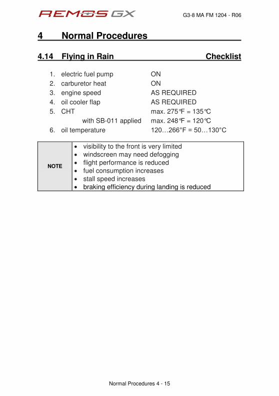
4.14 Flying in Rain Checklist
1. electric fuel pump ON
2. carburetor heat ON
3. engine speed AS REQUIRED
4. oil cooler flap AS REQUIRED
5. CHT max. 275°F = 135°C
with SB-011 applied max. 248°F = 120°C
6. oil temperature 342È488̇H"?"72È352̇E
NOTE
‚ visibility to the front is very limited
‚ windscreen may need defogging
‚ flight performance is reduced
‚ fuel consumption increases
‚ stall speed increases
‚ braking efficiency during landing is reduced
G3-8 MA FM 1204 - R06
4 Normal Procedures
Normal Procedures 4 - 16
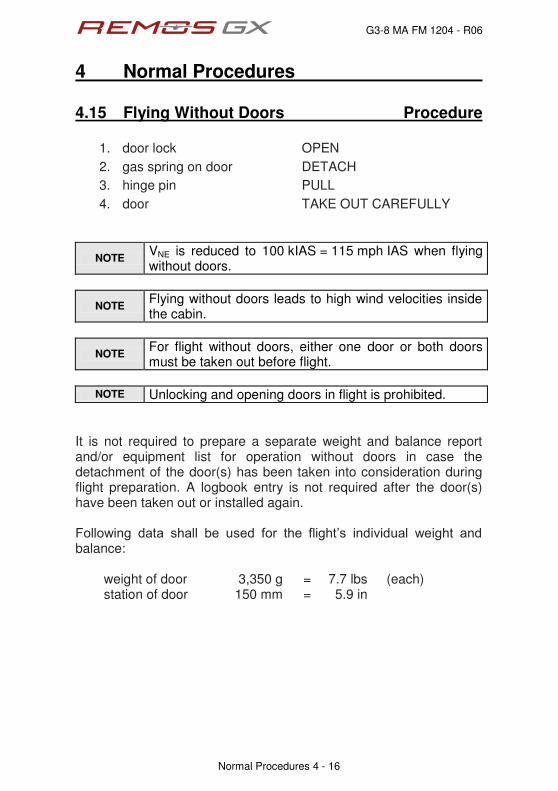
4.15 Flying Without Doors Procedure
1. door lock OPEN
2. gas spring on door DETACH
3. hinge pin PULL
4. door TAKE OUT CAREFULLY
NOTE VNE is reduced to 100 kIAS = 115 mph IAS when flying without doors.
NOTE Flying without doors leads to high wind velocities inside the cabin.
NOTE For flight without doors, either one door or both doors must be taken out before flight.
NOTE Unlocking and opening doors in flight is prohibited.
It is not required to prepare a separate weight and balance report and/or equipment list for operation without doors in case the detachment of the door(s) has been taken into consideration during flight preparation. A logbook entry is not required after the door(s) have been taken out or installed again. Hqnnqykpi" fcvc" ujcnn" dg" wugf" hqt" vjg" hnkijvÓu" kpfkxkfwcn" ygkijv" cpf"balance:
weight of door 3,350 g = 7.7 lbs (each) station of door 150 mm = 5.9 in

G3-8 MA FM 1204 - R06
4 Normal Procedures
Normal Procedures 4 - 17
4.16 Recovery from Stall Procedure
1. stick back pressure RELEASE
2. rudder OPPOSITE to BANK
3. aileron NEUTRAL
4. engine power AS REQUIRED
4.17 Descent Checklist
1. flaps CLEAN
2. engine speed AS REQUIRED
3. electric fuel pump ON
4. maneuvering speed VA = 88 kIAS = 101 mph IAS
5. normal operating speed VNO = 107 kIAS = 123 mph IAS
6. never exceed speed VNE = 135 kIAS = 155 mph IAS
7. max. cont. engine speed 5,500 rpm
8. carburetor heat RECOMMENDED
9. oil cooler flap AS REQUIRED
10. CHT max. 275°F = 135°C
with SB-011 applied max. 248°F = 120°C
11. oil temperature 342È488̇H"?"72È352̇E
G3-8 MA FM 1204 - R06
4 Normal Procedures
Normal Procedures 4 - 18
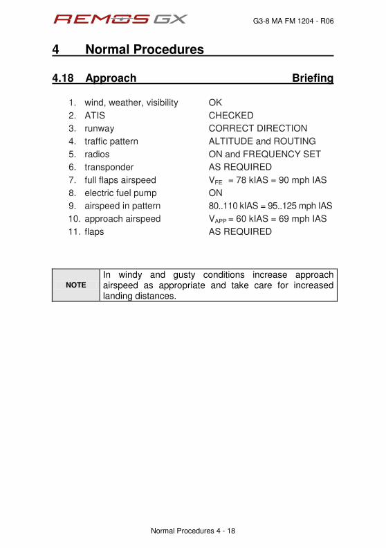
4.18 Approach Briefing
1. wind, weather, visibility OK
2. ATIS CHECKED
3. runway CORRECT DIRECTION
4. traffic pattern ALTITUDE and ROUTING
5. radios ON and FREQUENCY SET
6. transponder AS REQUIRED
7. full flaps airspeed VFE = 78 kIAS = 90 mph IAS
8. electric fuel pump ON
9. airspeed in pattern 80..110 kIAS = 95..125 mph IAS
10. approach airspeed VAPP = 60 kIAS = 69 mph IAS
11. flaps AS REQUIRED
NOTE
In windy and gusty conditions increase approach airspeed as appropriate and take care for increased landing distances.

G3-8 MA FM 1204 - R06
4 Normal Procedures
Normal Procedures 4 - 19
4.19 Landing Procedure
normal landing
1. full flaps airspeed VFE = 78 kIAS = 90 mph IAS
2. approach airspeed VAPP = 60 kIAS = 69 mph IAS
3. flaps DOWN
4. target airspeed AS RECOMMENDED
5. landing light RECOMMENDED
6. engine power AS REQUIRED
7. elevator trim AS REQUIRED
8. electric fuel pump ON
9. carburetor heat RECOMMENDED
10. oil cooler flap AS REQUIRED
11. CHT max. 275°F = 135°C
with SB-011 applied max. 248°F = 120°C
12. oil temperature 342È488̇H"?"72È352̇E
13. touch down on main wheels first
14. brakes IMMEDIATELY
The target airspeed (airspeed on short final, app. 50ft above threshold) differs with actual aircraft weight. Please refer to the following table to select the correct approach airspeed.
aircraft weight recommended approach speed
1,000 lb 48 kIAS = 55 mph IAS
1,100 lb 50 kIAS = 58 mph IAS
1,200 lb 52 kIAS = 60 mph IAS
1,320 lb 55 kIAS = 63 mph IAS
NOTE
Landing distances given in chapter 5 have been determined with approach airspeeds given above. Landing with partial flaps or clean is possible and permitted, but landing distance will be significantly longer due to higher approach speeds required by higher stall speed.
NOTE In high wind or gusty conditions less than full flap setting or clean flaps might be appropriate.

G3-8 MA FM 1204 - R06
4 Normal Procedures
Normal Procedures 4 - 20
short field landing
1. full flaps airspeed VFE = 78 kIAS = 90 mph IAS
2. approach airspeed VAPP = 60 kIAS = 69 mph IAS
3. flaps DOWN
4. target airspeed AS RECOMMENDED
5. landing light RECOMMENDED
6. engine power AS REQUIRED
7. elevator trim AS REQUIRED
8. electric fuel pump ON
9. carburetor heat RECOMMENDED
10. oil cooler flap AS REQUIRED
11. CHT max. 275°F = 135°C
with SB-011 applied max. 248°F = 120°C
12. oil temperature 342È488̇H"?"72È352̇E
13. touch down on main wheels first with very little flare
14. brakes AS REQUIRED
The target airspeed (airspeed on short final, app. 50ft above threshold) differs with actual aircraft weight. Please refer to the following table to select the correct approach airspeed.
aircraft weight recommended approach speed
1,000 lb 44 kIAS = 51 mph IAS
1,100 lb 46 kIAS = 53 mph IAS
1,200 lb 48 kIAS = 55 mph IAS
1,320 lb 50 kIAS = 58 mph IAS
NOTE
Landing distances given in chapter 5 have not been determined with this procedure, but with the procedure for standard landing. Landing distance with the short field technique varies significantly with precise handling and condition of the runway.
NOTE
Take care not to overload the landing gear during this maneuver. Take care not to stall the aircraft on final approach.

G3-8 MA FM 1204 - R06
4 Normal Procedures
Normal Procedures 4 - 21
soft field landing
1. full flaps airspeed VFE = 78 kIAS = 90 mph IAS
2. approach airspeed VAPP = 60 kIAS = 69 mph IAS
3. flaps DOWN
4. target airspeed AS RECOMMENDED
5. landing light RECOMMENDED
6. engine power AS REQUIRED
7. elevator trim AS REQUIRED
8. electric fuel pump ON
9. carburetor heat RECOMMENDED
10. oil cooler flap AS REQUIRED
11. CHT max. 275°F = 135°C
with SB-011 applied max. 248°F = 120°C
12. oil temperature 342È488̇H"?"72È352̇E
13. touch down on main wheels first with very little flare
14. brakes CAREFULLY The target airspeed (airspeed on short final, app. 50ft above threshold) differs with actual aircraft weight. Please refer to the following table to select the correct approach airspeed.
aircraft weight recommended approach speed
1,000 lb 44 kIAS = 51 mph IAS
1,100 lb 46 kIAS = 53 mph IAS
1,200 lb 48 kIAS = 55 mph IAS
1,320 lb 50 kIAS = 58 mph IAS
NOTE
Landing distances given in chapter 5 have not been determined with this procedure, but with the procedure for standard landing. Landing distance with the soft field technique varies significantly with precise handling and condition of the runway.
NOTE
Take care not to overload the landing gear during this maneuver. Take care not to stall the aircraft on final approach.

G3-8 MA FM 1204 - R06
4 Normal Procedures
Normal Procedures 4 - 22
4.20 Balked Landing Procedure
1. engine power FULL POWER
2. carburetor heat OFF
3. flaps RETRACT
4. steepest climb VX Flaps 15 = 39 kIAS = 45 mph IAS
VX clean = 51 kIAS = 59 mph IAS
5. best climb VY Flaps 15 = 58 kIAS = 67 mph IAS
VY clean = 60 kIAS = 69 mph IAS
6. electric fuel pump ON
7. oil cooler flap AS REQUIRED
8. CHT max. 275°F = 135°C
with SB-011 applied max. 248°F = 120°C
9. oil temperature 342È488̇H"?"72È352̇E
4.21 After Landing Checklist
1. landing light RECOMMENDED
2. flaps UP
3. electric fuel pump OFF
4. radio and transponder AS REQUIRED

G3-8 MA FM 1204 - R06
4 Normal Procedures
Normal Procedures 4 - 23
4.22 Shutdown Procedure
1. avionics switch OFF
2. landing light OFF
3. position lights OFF
4. engine OFF
5. ACL OFF
6. cockpit lights OFF
7. master switch OFF
8. recovery system SECURED
9. parking brake SET
NOTE
It is permissible to switch avionics (GPS, radio, transponder, intercom) together with the avionics switch rather than separately.
NOTE It is permissible to lights and fuel pump together with the master switch rather than separately.
G3-8 MA FM 1205 - R06
5 Performance
Performance 5 - 1
Table of Contents
sect. description page
5.1 General 5-2
5.2 Take-Off and Landing Distances 5-3
5.3 Rate of Climb 5-5
5.4 Cruise Speed, RPM, Fuel Consumption, Range 5-5
5.5 Low Airspeed and Stall 5-7

G3-8 MA FM 1205 - R06
5 Performance
Performance 5 - 2
5.1 General All flight performance data are given for ISA standard atmosphere at sea level and standard temperature. To determine temperature in relation to ISA conditions please refer to the following chart:
ISA std. Temperature
0
1000
2000
3000
4000
5000
6000
7000
8000
9000
10000
11000
12000
13000
14000
15000
-15 -10 -5 0 5 10 15
temperature [ °C ]
pre
ssu
re a
ltit
ud
e
[
ft ]
Flight performance can vary significantly due to tolerances, setting of propeller and engine, flight without doors, deviation of temperature and air density from standard ISA conditions, etc. Range applies to the 22 gallon fuel tank system (21 gallons usable) without reserve, within the ICAO standard atmosphere at given altitude.

G3-8 MA FM 1205 - R06
5 Performance
Performance 5 - 3
5.2 Take-Off and Landing Distances
Take-Off Woodcomp or Tonini
Sensenich or Neuform
Take-off roll distance (Flaps 0°)
ft m
n/a 770 ft 234 m
Take-off air distance (Flaps 0°)
ft m
n/a 421 ft 128 m
Take-off distance (Flaps 0°)
ft m
n/a 1.191 ft 362 m
Take-off roll distance (Flaps 15°)
ft m
757 ft 230 m
615 ft 187 m
Take-off air distance (Flaps 15°)
ft m
424 ft 129 m
441 ft 134 m
Take-off distance (Flaps 15°)
ft m
1.134 ft 345 m
1.056 ft 321 m
Landing all propellers
Landing roll distance (Flaps 40°)
ft m
306 ft 93 m
Landing air distance (Flaps 40°)
ft m
461 ft 140 m
Landing distance (Flaps 40°)
ft m
766 ft 233 m
NOTE
Take-off/landing conditions have been determined at ISA standard conditions at mean sea level and over a virtual 50ft obstacle.
NOTE
Standard procedures apply. Diverting from the standard procedures defined in section 4 will lead to different take-off and landing distances.
G3-8 MA FM 1205 - R06
5 Performance
Performance 5 - 4
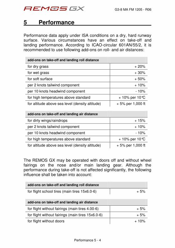
Performance data apply under ISA conditions on a dry, hard runway surface. Various circumstances have an effect on take-off and landing performance. According to ICAO-circular 601AN/55/2, it is recommended to use following add-ons on roll- and air distances:
add-ons on take-off and landing roll distance
for dry grass + 20%
for wet grass + 30%
for soft surface + 50%
per 2 knots tailwind component + 10%
per 10 knots headwind component - 10%
for high temperatures above standard + 10% per 10°C
for altitude above sea level (density altitude) + 5% per 1,000 ft
add-ons on take-off and landing air distance
for dirty wings/raindrops + 15%
per 2 knots tailwind component + 10%
per 10 knots headwind component - 10%
for high temperatures above standard + 10% per 10°C
for altitude above sea level (density altitude) + 5% per 1,000 ft
The REMOS GX may be operated with doors off and without wheel fairings on the nose and/or main landing gear. Although the performance during take-off is not affected significantly, the following influence shall be taken into account:
add-ons on take-off and landing roll distance
for flight school tires (main tires 15x6.0-6) + 5%
add-ons on take-off and landing air distance
for flight without fairings (main tires 4.00-6) + 5%
for flight without fairings (main tires 15x6.0-6) + 5%
for flight without doors + 10%

G3-8 MA FM 1205 - R06
5 Performance
Performance 5 - 5
5.3 Rate of Climb
Propeller Woodcomp or Tonini
Sensenich Neuform
best angle of climb
airspeed VX
kIAS mph IAS
51 59
51 59
51 59
best rate of climb
airspeed VY
kIAS mph IAS
60 69
60 69
60 69
best rate of climb
at MSL fpm 600 840 840
NOTE Climb is flown with flaps retracted, see section 4
NOTE Expect a performance loss of about 5% when flying without wheel fairings.
NOTE Expect a performance loss of about 10% when flying without doors
5.4 Cruise Speed, RPM, Fuel Consumption, Range Rotax 912 UL-S, 100 hp engine, Woodcomp or Tonini Fixed Pitch Prop
engine speed fuel flow true airspeed endurance range [ rpm ] [ gph ] [ kTAS ] [ mph true ] [ h ] [ nm ]
5.400 6,7 98 113 3,1 304
5.200 6,0 95 109 3,5 333
5.000 5,4 91 105 3,9 355
4.800 4,9 87 100 4,3 374 4.600 4,4 83 95 4,8 398
4.400 3,9 79 91 5,4 427
4.200 3,5 75 86 6,0 450
G3-8 MA FM 1205 - R06
5 Performance
Performance 5 - 6
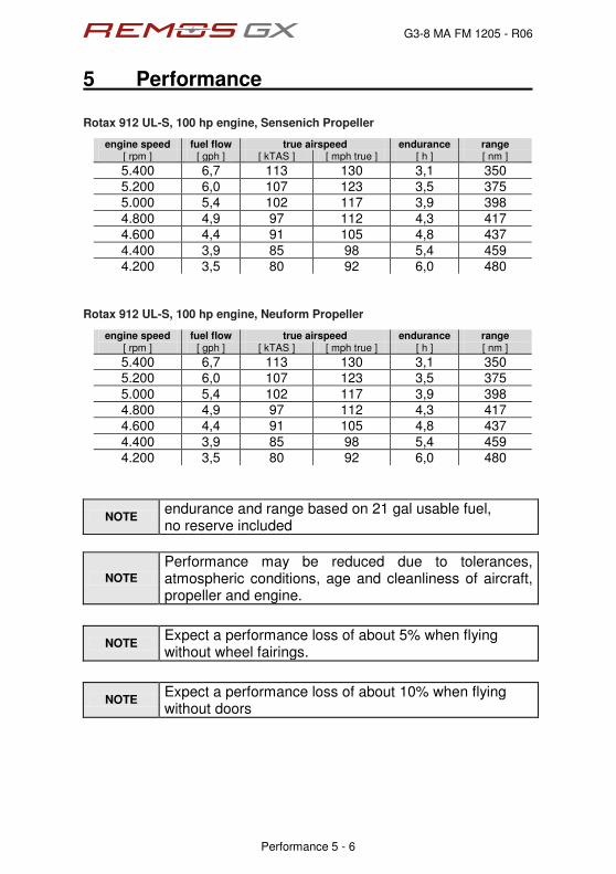
Rotax 912 UL-S, 100 hp engine, Sensenich Propeller
engine speed fuel flow true airspeed endurance range [ rpm ] [ gph ] [ kTAS ] [ mph true ] [ h ] [ nm ]
5.400 6,7 113 130 3,1 350
5.200 6,0 107 123 3,5 375 5.000 5,4 102 117 3,9 398
4.800 4,9 97 112 4,3 417 4.600 4,4 91 105 4,8 437
4.400 3,9 85 98 5,4 459 4.200 3,5 80 92 6,0 480
Rotax 912 UL-S, 100 hp engine, Neuform Propeller
engine speed fuel flow true airspeed endurance range [ rpm ] [ gph ] [ kTAS ] [ mph true ] [ h ] [ nm ]
5.400 6,7 113 130 3,1 350 5.200 6,0 107 123 3,5 375
5.000 5,4 102 117 3,9 398 4.800 4,9 97 112 4,3 417
4.600 4,4 91 105 4,8 437
4.400 3,9 85 98 5,4 459
4.200 3,5 80 92 6,0 480
NOTE endurance and range based on 21 gal usable fuel, no reserve included
NOTE
Performance may be reduced due to tolerances, atmospheric conditions, age and cleanliness of aircraft, propeller and engine.
NOTE Expect a performance loss of about 5% when flying without wheel fairings.
NOTE Expect a performance loss of about 10% when flying without doors
G3-8 MA FM 1205 - R06
5 Performance
Performance 5 - 7
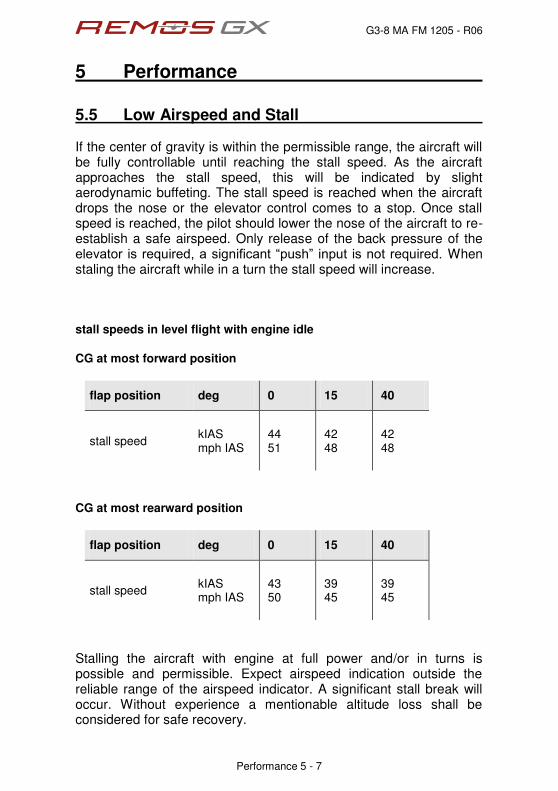
5.5 Low Airspeed and Stall If the center of gravity is within the permissible range, the aircraft will be fully controllable until reaching the stall speed. As the aircraft approaches the stall speed, this will be indicated by slight aerodynamic buffeting. The stall speed is reached when the aircraft drops the nose or the elevator control comes to a stop. Once stall speed is reached, the pilot should lower the nose of the aircraft to re-establish a safe airspeed. Only release of the back pressure of the gngxcvqt" ku"tgswktgf."c"ukipkhkecpv"ÐrwujÑ" kprwv" ku"pqv"tgswktgf0 When staling the aircraft while in a turn the stall speed will increase. stall speeds in level flight with engine idle
CG at most forward position
flap position deg 0 15 40
stall speed kIAS mph IAS
44 51
42 48
42 48
CG at most rearward position
flap position deg 0 15 40
stall speed kIAS mph IAS
43 50
39 45
39 45
Stalling the aircraft with engine at full power and/or in turns is possible and permissible. Expect airspeed indication outside the reliable range of the airspeed indicator. A significant stall break will occur. Without experience a mentionable altitude loss shall be considered for safe recovery.

G3-8 MA FM 1206 - R05
6 Weight-and-Balance-Information
Weight and Balance Information 6 - 1
Table of Contents
sect. description page
6.1 Center of Gravity Range and Determination 6-2
6.2 CG-Calculation 6-3
6.3 Calculation Example 6-4
6.4 Aircraft Specific Weights 6-5

G3-8 MA FM 1206 - R05
6 Weight-and-Balance-Information
Weight and Balance Information 6 - 2
6.1 Center of Gravity Range and Determination Vq"fgvgtokpg"ÐEIÑ."rwv"vjg"cktetchv"qp"5"ygkijkpi"uecngu."rqukvkqpgf"on a level surface. Before weighing, a level wing main chord has to be established (use pads between main wheels and scale beneath). A check-mark reference point (R.P.) on the leading edge of the left wing, adjacent to the wing root, is provided to ease examination. To level the wing main chord, use a flexible clear hose, filled with water, as a spirit level. The total weight G = G1 + G2, has to be used for ecnewncvkpi"ÐEIÑ."nqecvgf"cv"vjg fkuvcpeg"ÐZÑ"dgjkpf"T0R0
G3-8 MA FM 1206 - R05
6 Weight-and-Balance-Information
Weight and Balance Information 6 - 3
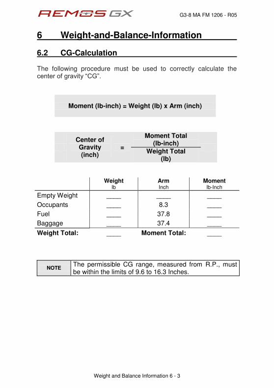
6.2 CG-Calculation The following procedure must be used to correctly calculate the egpvgt"qh"itcxkv{"ÐEIÑ0
Moment (lb-inch) = Weight (lb) x Arm (inch)
Center of Gravity (inch)
=
Moment Total (lb-inch)
Weight Total
(lb)
Weight
lb Arm Inch
Moment lb-Inch
Empty Weight ____ ____ ____ Occupants ____ 8.3 ____ Fuel ____ 37.8 ____ Baggage ____ 37.4 ____
Weight Total: ____ Moment Total: ____
NOTE The permissible CG range, measured from R.P., must be within the limits of 9.6 to 16.3 Inches.

G3-8 MA FM 1206 - R05
6 Weight-and-Balance-Information
Weight and Balance Information 6 - 4
6.3 Calculation Example The following example is given to show how to calculate the center qh"itcxkv{" ÐEIÐ0"Fq"pqv"wug" vjg"ygkijvu"cpf" vjg"gorv{"E0I0" kp" vjku"example for your own flight preparation.
Weight
lb Arm Inch
Moment lb-Inch
Empty Weight 670 12.5 8,375
Occupants 175 8.3 1,453
Fuel 120 37.8 4,536
Baggage 30 37.4 1,122
Weight Total: 995 Moment Total: 15,486
Center of Gravity (inch)
=
Moment Total (lb-inch)
= 15.6 inch Weight Total
(lb)

G3-8 MA FM 1206 - R05
6 Weight-and-Balance-Information
Weight and Balance Information 6 - 5
6.4 Aircraft Specific Weights Below are noted the aircraft specific data. Pilots must use this information to ensure a correct weight and balance calculation prior to every flight. This is essential for safe flight. For detailed information of the weight and balance data and the equipment installed on the aircraft refer to the individual aircraft weight and balance report, which includes the equipment list.
empty weight
payload C.G. date of weighing
date of list of equipment
sign

G3-8 MA FM 6207 - R02
7 Airplane and Systems Description
Systeme 7 - 1
Table of Contents
sect. description pages
7.1 General 7-2
7.2 Airframe 7-2
7.3 Control System 7-8
7.4 Cockpit Overview 7-12
7.5 Left Panel Î Primary Instruments 7-13
7.6 Engine Operation 7-18
7.7 Center Stack 7-19
7.8 Right Panel Î Additional Instruments 7-21
7.9 Circuit Breakers 7-24
7.10 Electrical System 7-26
7.11 Center Console 7-28
7.12 Cockpit Lighting 7-29
7.13 Recovery System 7-30
7.14 Engine 7-31
7.15 Propeller 7-32
7.16 Fuel System 7-33
7.17 Brake System 7-36
7.18 Special Equipment and Customizing 7-37

G3-8 MA FM 6207 - R02
7 Airplane and Systems Description
Systeme 7 - 2
7.1 General This section of the POH shall give a brief introduction into the sys-tems installed in the REMOS GX. For further information, mainte-nance and repair instructions see maintenance manual, latest revi-sion.
7.2 Airframe Type: Full composite carbon fiber aircraft with two seats. Design: High wing design with struts, front mounted engine
and propeller, traditional stabilizer concept, differen-tial ailerons. Electrically operated flaps (0° to 40°), electric elevator trim, three-wheel landing gear with steerable nose wheel. Main gear with hydraulic disc brakes. The cabin is equipped with two seats side by side and can be entered and exited by doors on the left and right side of the fuselage.
Layout: Main components are built in half shells from compo-
site fiber material, which are bonded together (car-bon fiber, Kevlar and glass fiber).

G3-8 MA FM 6207 - R02
7 Airplane and Systems Description
Systeme 7 - 3
assembly of the wing
The wing consists of four main pars: wingbox, flap, aileron and wing-tip. The wingtip is bolted to the wingbox, aileron and flap are hinged to allow control movements. The wing is completes by the cover glass of the landing light and the main wingbolt which attaches the wing to the fuselage. All loads are supported by the wingbolt and the strut.
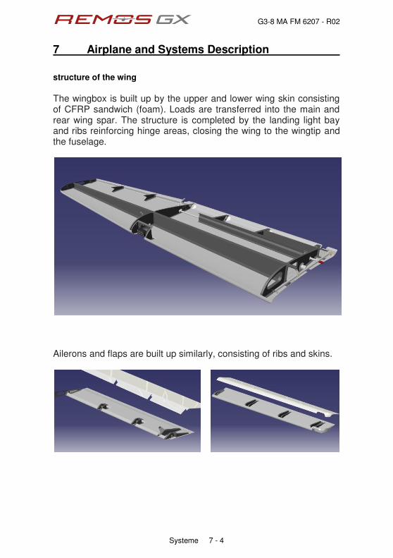
G3-8 MA FM 6207 - R02
7 Airplane and Systems Description
Systeme 7 - 4
structure of the wing
The wingbox is built up by the upper and lower wing skin consisting of CFRP sandwich (foam). Loads are transferred into the main and rear wing spar. The structure is completed by the landing light bay and ribs reinforcing hinge areas, closing the wing to the wingtip and the fuselage.
Ailerons and flaps are built up similarly, consisting of ribs and skins.

G3-8 MA FM 6207 - R02
7 Airplane and Systems Description
Systeme 7 - 5
structure of the fuselage
The skins of the fuselage are build of a monolithic layup of glass, carbon and Kevlar, reinforced by carbon tapes. Sandwich material (foam) is found in the fixed surface of the vertical tail only, which is an integral part of the fuselage. The fuselage skin is stiffened by stringers and frames.

G3-8 MA FM 6207 - R02
7 Airplane and Systems Description
Systeme 7 - 6
attachment of struts
The wing strut is attached towards the wing and fuselage by a high tensile bolt, which is a genuine REMOS part. The wing strut can pivot about its axis some degree in order to allow the wing to be folded. The strut consists of a stainless steel tube with fork ends, covered with a fairing made from GFRP. A carbon strut for reduced weight is available.

G3-8 MA FM 6207 - R02
7 Airplane and Systems Description
Systeme 7 - 7
installation of horizontal tail
The horizontal tail is made from GFRP. It is built up similar as the wing structure, consisting of ribs and spars. The elevator included a trim tab, which is operated electrically. The trim tab does not have a dedicated hinge, but uses the elastic flap technology; the upper skin is used as hinge. Two horns are integral parts of the elevator containing counter-weights in order to balance the moving surface.

G3-8 MA FM 6207 - R02
7 Airplane and Systems Description
Systeme 7 - 8
7.3 Control System The control system is made of aluminium pushrods and crank bells for the elevator and aileron controls. The rudder is operated by steel cables. The trim system is an electrically driven trim tab on the eleva-tor; aileron and rudder have ground adjustable tabs. rudder control system
Rudder control is maintained through use of conventional rudder pedals which also control nose wheel steering. The system is com-prised of rudder pedals, a steering rod (sliding translator) towards the nose wheel dip tube, cables and pulleys, all of which link the pedals to the rudder and nose wheel steering.

G3-8 MA FM 6207 - R02
7 Airplane and Systems Description
Systeme 7 - 9
elevator control system
The control sticks are installed to a pivoting connection element (stick bridge). Thereby a push/pull input stick is transferred from the control stick through a bell crank and a push-pull tube towards the elevator. An electrical operated elevator trim tab is installed on the elevator. The elevator control system is connected to the elevator by a quick connector to allow the tailplane to be detached from the aircraft. Checking this quick connector is part of the preflight check! Insecurely connected, improper operation of control surfaces or inse-
curely locked fasteners will lead to loss of control of the aircraft!!
Checks inside the aircraft

G3-8 MA FM 6207 - R02
7 Airplane and Systems Description
Systeme 7 - 10
aileron control system
Both control sticks are linked together by a control rod system to ensure synchronous movement. The linkage is located beneath two fiberglass-panels on the floor of the cabin right in front of the seats. A translator connects the control stick linkage to the aileron linkage, which uses several bell cranks to establish the connection to the control surfaces. The aileron control system is split between the elements installed in the fuselage and in the wing. Both parts are connected by a con-nector. This connector is a quick connector to allow the wings to be folded. Checking these quick connectors is part of the preflight check! Insecurely connected, improper operation of control surfaces or inse-
curely locked fasteners will lead to loss of control of the aircraft!!
Checks inside the aircraft

G3-8 MA FM 6207 - R02
7 Airplane and Systems Description
Systeme 7 - 11
flying with only one control stick installed
Under certain conditions it might be favorable to have only one con-trol stick installed. It is permissible to take out the control stick on the passenger side. See section 2 for the definition of the seat of the pilot in command.
Take out the bolts on the side where the stick shall be uninstalled. Take out the stick. Newer aircraft have the trim and PTT buttons wired with a connector so the stick can be left outside the aircraft. In elder aircraft the stick must be stowed safely. Re-install the mounting ring by means of the bolts.
bolts
stick
ring

G3-8 MA FM 6207 - R02
7 Airplane and Systems Description
Systeme 7 - 12
7.4 Cockpit Overview Cockpit example
center panel and switchboard
circuit breakers
engine operating elements
COM or NAV/COM
backup Instruments
ELT intercom or
audio panel

G3-8 MA FM 6207 - R02
7 Airplane and Systems Description
Systeme 7 - 13
7.5 Left Panel DYNON SV-D700
The instrumentation in the left panel consists of the DYNON SkyView SV D700 glass cockpit, a GARMIN radio (COM or NAV/COM), back-up altimeter and airspeed indicator. The engine controls are located in a group on the far left of the panel
The primary flight instrumentation and engine indication are realized by the DYNON SkyView SV-D700 glass cockpit system. This is an integrated system, it includes the ÐGngevtonic Flight information dis-play and the ãOwnvkpcvkqpcn"Hwpevkqp"Dkurnc{Ð. Any primary and sec-ondary flight instruments as well as navigation and engine instru-ments are shown on the screen.
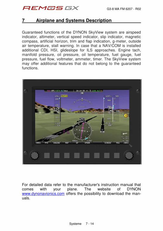
G3-8 MA FM 6207 - R02
7 Airplane and Systems Description
Systeme 7 - 14
Guaranteed functions of the DYNON SkyView system are airspeed indicator, altimeter, vertical speed indicator, slip indicator, magnetic compass, artificial horizon, trim and flap indication, g-meter, outside air temperature, stall warning. In case that a NAV/COM is installed additional CDI, HSI, glideslope for ILS approaches. Engine tach, manifold pressure, oil pressure, oil temperature, fuel gauge, fuel pressure, fuel flow, voltmeter, ammeter, timer. The SkyView system may offer additional features that do not belong to the guaranteed functions.
For detailed data refer to the manufacturer's instruction manual that comes with your plane. The website of DYNON www.dynonavionics.com offers the possibility to download the man-uals.

G3-8 MA FM 6207 - R02
7 Airplane and Systems Description
Systeme 7 - 15
GARMIN SL40
The GARMIN SL40 is a 760-channel VHF COM transceiver with 25kHz frequency channel spacing. It incorporates active and standby flip-flop frequency tuning. Its frequency monitor function allows to check ATIS or emergency frequencies without leaving the assigned ATC channel
GARMIN GTR225A
The GARMIN GTR225A is a VHF COM transceiver with 8.33kHz frequency channel spacing. In addition to the COMM features of an SL40, the GTR 225 incorpo-rates a number of functions that save time and effort. Provide the GTR 225 with an airport identifier and it will automatically find its frequency (and vice versa) thanks to a built-in, updateable database. The database technology also allows to store and recall commonly used or recently used frequencies by an assigned name. All infor-mation is displayed prominently on the device's large sunlight-readable LCD display.
For detailed data refer to the manufacturer's instruction manual that comes with your airplane. The website of GARMIN www.garmin.com offers the possibility to download the manuals.
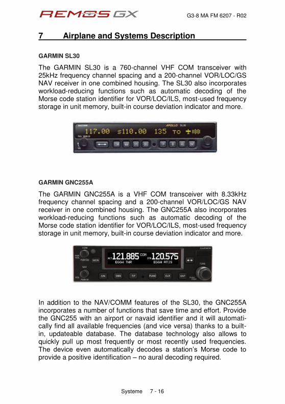
G3-8 MA FM 6207 - R02
7 Airplane and Systems Description
Systeme 7 - 16
GARMIN SL30
The GARMIN SL30 is a 760-channel VHF COM transceiver with 25kHz frequency channel spacing and a 200-channel VOR/LOC/GS NAV receiver in one combined housing. The SL30 also incorporates workload-reducing functions such as automatic decoding of the Morse code station identifier for VOR/LOC/ILS, most-used frequency storage in unit memory, built-in course deviation indicator and more.
GARMIN GNC255A
The GARMIN GNC255A is a VHF COM transceiver with 8.33kHz frequency channel spacing and a 200-channel VOR/LOC/GS NAV receiver in one combined housing. The GNC255A also incorporates workload-reducing functions such as automatic decoding of the Morse code station identifier for VOR/LOC/ILS, most-used frequency storage in unit memory, built-in course deviation indicator and more.
In addition to the NAV/COMM features of the SL30, the GNC255A incorporates a number of functions that save time and effort. Provide the GNC255 with an airport or navaid identifier and it will automati-cally find all available frequencies (and vice versa) thanks to a built-in, updateable database. The database technology also allows to quickly pull up most frequently or most recently used frequencies. Vjg" fgxkeg" gxgp" cwvqocvkecnn{" fgeqfgu" c" uvcvkqpÓu" Oqtug" eqfg" vq"provide a positive identification Î no aural decoding required.

G3-8 MA FM 6207 - R02
7 Airplane and Systems Description
Systeme 7 - 17
Both NAV/COM radios offer standby frequency monitoring of NAV and COM providing the capability of two NAV/COMS in one. Standby COM frequency monitoring lets the pilot listen to transmis-sions like ATIS or the emergency channel without leaving the active frequency. With the primary VOR/LOC frequency selected as NAV source on the DYNON SV-700, the standby frequency can be tuned to a se-cond VOR to display the current radial on which your aircraft is flying and be displayed as BEARING source on the SV-700. This allows you to cross check position fixes with just one receiver, the standby-VOR tuned in serves as an NDB in this case. For detailed data refer to the manufacturer's instruction manual that comes with your plane. The website of GARMIN www.garmin.com offers the possibility to download the manuals.

G3-8 MA FM 6207 - R02
7 Airplane and Systems Description
Systeme 7 - 18
7.6 Engine Operation
Left Panel
Carburetor heating is activated by pulling the yellow knob on top The oil temperature control is installed in the middle position. Push to increase temperature, pull to decrease temperature. Pull the green knob to choke the engine. The dual throttle control is located in the lower position. The left throttle lever does not feature a friction lock.

G3-8 MA FM 6207 - R02
7 Airplane and Systems Description
Systeme 7 - 19
7.7 Center Stack The GPS is installed in the center stack. A Garmin aera 500, a Gar-min 696 or the FlymapL is available.

G3-8 MA FM 6207 - R02
7 Airplane and Systems Description
Systeme 7 - 20
At the central control panel all controls of the REMOS GX are locat-ed. All switches are clearly labeled.
The switch panel incorporates the following:
‚ Switch for ACL
‚ Navigation lights
‚ Switch for landing lights
‚ Switch for fuel pump
‚ Throttle lever with locking device
‚ Charging indicator light of the generator
‚ Master and avionics switches
‚ USB sockets
‚ Dimmer LED Cockpit
‚ Audio connection

G3-8 MA FM 6207 - R02
7 Airplane and Systems Description
Systeme 7 - 21
7.8 Right Panel Î Additional Instruments The right cockpit panel takes different equipment and operating de-vices depending on equipment. The illustration below shows a pos-sible configuration, consisting of the ELT switch as well as a second DYNON SV-700 screen. Standard equipment in the right panel in-cludes the ventilation and heating knobs, circuit breakers, 12V recep-tacle and the intercom or audio panel.

G3-8 MA FM 6207 - R02
7 Airplane and Systems Description
Systeme 7 - 22
Garmin GMA 240
The Garmin GMA240 is an intercom with audio-in capability. Marker beacons cannot be received. Left and right volume and squelch can be adjusted separately. The center panel is equipped with an audio-in jack. Activate the audio-kp" ukipcn" d{" rtguukpi" ÐOWUKEÑ" cpf" vjgp"ugngevkpi"Ðæ3Ñ0"Vq"cflwuv"vjg"xqnwog."rwnn"vjg"right knob and rotate it.
WARNING
Listening to music during flight may lead to inatten-tion. Take care that you are always aware of the situation of the flight and stay ahead of the aircraft. If in doubt, switch off the audio entertainment, espe-cially during take-off, landing and while talking with ATC.
The GARMIN GMA240 is a stereo intercom designed to be used in combination with stereo headsets. The wiring of the aircraft is de-signed to use stereo headsets, too. To allow the use of mono-headsets, the aircraft is equipped with stereo/mono switches at the headset jacks. Make sure the switch is in its correct position. If mono headsets are plugged in while the switch is in stereo posi-tion, the signal for the right channel will short out with ground. This may lead to damage of the intercom, as described in the GARMIN GMA240 manual. Furthermore the radio may be damaged, too. The intercom may be damaged, too, if the headset is plugged in or pulled or out while the intercom is switched on. Always shut down the intercom when connecting or disconnecting headsets.
NOTE
The warranty does not apply if the intercom or the radio fail when using mono headsets with the incorrect posi-tion of the stereo/mono switch or when plugging in or disconnecting headsets while the intercom is switched on.
For detailed data refer to the manufacturer's instruction manual that comes with your plane. The website of GARMIN www.garmin.com offers the possibility to download the manuals.

G3-8 MA FM 6207 - R02
7 Airplane and Systems Description
Systeme 7 - 23
ps-engineering PMA8000BT
This is an audio panel with marker beacon receiver. It incorporates audio-in capability with several muting modes. The audio panel may be used with mono or stereo headsets. A common volume knob is provided for left and right seat. Setting squelch is not required as the audio panels incorporate INTELLI-VOX that adjusts squelch automatically. In addition to that the PMA8000BT audio panel incorporates BLUETOOTH ® interface to link your cellphone or iPhone® without additional cables.
WARNING
Listening to music during flight may lead to inatten-tion. Take care that you are always aware of the situation of the flight and stay ahead of the aircraft. If in doubt, switch off the audio entertainment, espe-cially during take-off, landing and while talking with ATC.
WARNING National regulations may apply or using cell phones on board of aircraft.
For detailed data refer to the manufacturer's instruction manual that comes with your plane. The website of ps-engineering www.ps-engineering.com offers the possibility to download the man-uals.

G3-8 MA FM 6207 - R02
7 Airplane and Systems Description
Systeme 7 - 24
7.9 Circuit Breakers The electrical system of the REMOS GX consists of a BUS system, split into master-BUS and avionics-BUS. All electrical components are protected with circuit breakers (CB). The fuse for the charge control check light is located behind the switch panel. An additional fuse for charging and for the regulator is located in front of the fire-wall, beneath the battery bracket.
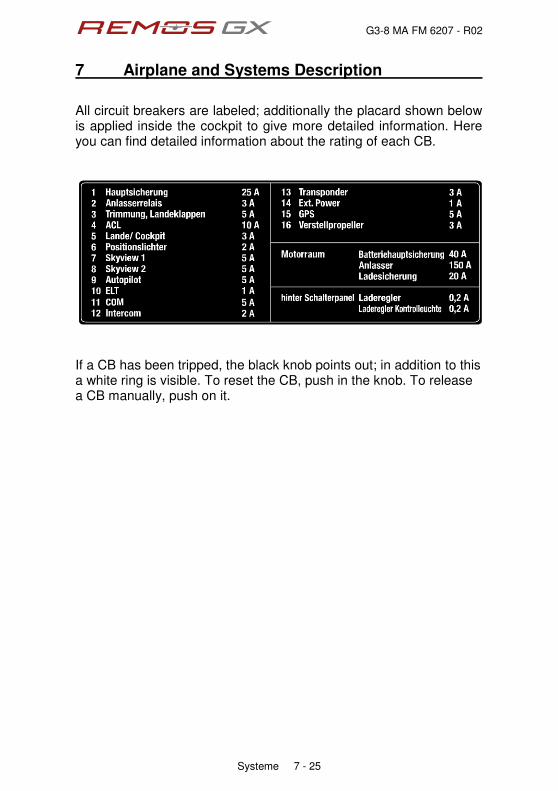
G3-8 MA FM 6207 - R02
7 Airplane and Systems Description
Systeme 7 - 25
All circuit breakers are labeled; additionally the placard shown below is applied inside the cockpit to give more detailed information. Here you can find detailed information about the rating of each CB.
If a CB has been tripped, the black knob points out; in addition to this a white ring is visible. To reset the CB, push in the knob. To release a CB manually, push on it.

G3-8 MA FM 6207 - R02
7 Airplane and Systems Description
Systeme 7 - 26
7.10 Electrical System The electrical system of the REMOS GX is powered by an alternator, which is capable of 250W at engine speeds of at least 4,000 RPM. At lower engine speeds the output of the alternator is lower. Below a certain engine speed the alternator is not able to support the power demand for all electrical equipment. The exact engine speed is not easily defined and varies base on the equipment installed. The criti-cal engine speed is around 2,500 RPM. If your REMOS GX is operated in an environment where you have long taxiways or you operate the aircraft a longer time with low RPM, switch off electrical equipment that are not essential in order to con-serve battery power. The following table gives an overview of the power consumption of your electrical equipment.
consumer average power
consumption [ W ] average current
@ 12V [ A ]
DYNON SkyView SV-D700 (each) 28 2,3
DYNON SkyView SV-ADAHRS-200 1 0,1
DYNON SkyView SV-EMS-220 1 0,1
DYNON SkyView SV-GPS-250 1 0,1
DYNON SkyView SV-XPNDR-261 4 0,3
DYNON SkyView SV-32 (each) 17 1,4
GARMIN SL30 (standby) 11 0,9
GARMIN SL30 (TX) 50 4,2
GARMIN GNC255A (standby) 44 1,2
GARMIN GNC255A (TX) 65 5,4
GARMIN SL40 (standby) 5 0,4
GARMIN SL40 (TX) 40 3,3
GARMIN GTR225A (standby) 7 0,6
GARMIN GTR225A (TX) 50 4,2
GARMIN aera500 6 0,5
GARMIN GPS-696 13 1,1
FlymapL 42 3,5
intercom / audio panel 5 0,4
fuel pump 17 1,4

G3-8 MA FM 6207 - R02
7 Airplane and Systems Description
Systeme 7 - 27
consumer average power
consumption [ W ] average current
@ 12V [ A ]
instrument lighting 6 0,5
aeroLEDs position lights 40 3,3
aeroLEDs landing lights 24 2,0
flap motor 4 0,3
trim Motor 25 2,1
external receptacle 12 1,0
The aircraft is equipped with an ammeter, so the energy balance can be read. The ammeter is installed in a way that only the current into and out of the battery is indicated. Below the critical engine speed the battery will be discharged, indicated by negative current. When reaching the critical engine speed the indicated current will become zero. Above that speed the battery is charged, indicated by positive current.
NOTE
With engine idling or when taxiing with low RPM the alternator is definitely not able to cover the electric pow-er consumption and the battery will be discharged.
recommendations
Charge your battery on a regular basis, especially in the cold time of the year. Take care to use the correct charger. Standard equipment is a LiFePo4 battery that needs a special kind of charger. To avoid damage to the battery, do not use inappropriate or inexpensive chargers. Contact REMOS for recommendations of appropriate charging systems. Take the battery out of the aircraft in winter time if you do not fly and stow it in a dry place at room temperature. Aircraft owners that oper-ate their REMOS GX throughout the entire year, even in the cold winter time, are strongly recommended to use at least a 12Ah battery and to install a TANIS heater system for both the battery and the engine. Contact REMOS or your dealer for certified installation of the heater systems.

G3-8 MA FM 6207 - R02
7 Airplane and Systems Description
Systeme 7 - 28
7.11 Center Console The following controls are located on the center console:
‚ Engine fuel shut off valve ‚ Brake lever including fluid reservoir
‚ Parking brake valve
All controls are labeled. On the center console you will find all im-portant placards, which post the operational limits for a safe opera-tion of the aircraft. In addition a start-up checklist is provided

G3-8 MA FM 6207 - R02
7 Airplane and Systems Description
Systeme 7 - 29
7.12 Cockpit Lighting
The REMOS GX cockpit features an effective LED panel lighting system, which can be dimmed independently from the instrument lights. It is a dazzle-free system designed for Night-VFR use.
The system is activated and dimmed by means of the control knob located on the center stack left of the power lever.
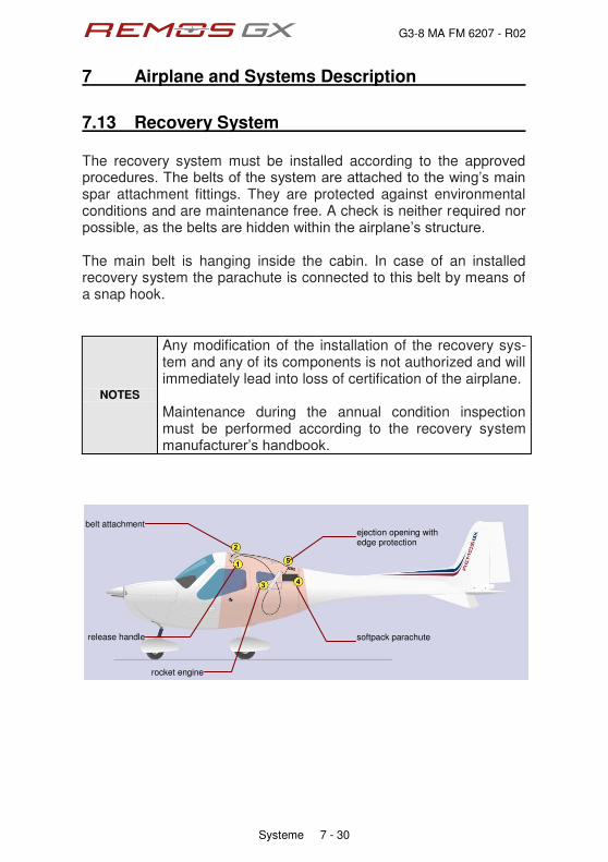
G3-8 MA FM 6207 - R02
7 Airplane and Systems Description
Systeme 7 - 30
7.13 Recovery System The recovery system must be installed according to the approved rtqegfwtgu0"Vjg"dgnvu"qh"vjg"u{uvgo"ctg"cvvcejgf"vq"vjg"ykpiÓu"ockp"spar attachment fittings. They are protected against environmental conditions and are maintenance free. A check is neither required nor rquukdng."cu"vjg"dgnvu"ctg"jkffgp"ykvjkp"vjg"cktrncpgÓu"uvtwevwtg0" The main belt is hanging inside the cabin. In case of an installed recovery system the parachute is connected to this belt by means of a snap hook.
NOTES
Any modification of the installation of the recovery sys-tem and any of its components is not authorized and will immediately lead into loss of certification of the airplane. Maintenance during the annual condition inspection must be performed according to the recovery system ocpwhcevwtgtÓu"jcpfdqqm0
release handle
belt attachment
rocket engine
softpack parachute
ejection opening with edge protection

G3-8 MA FM 6207 - R02
7 Airplane and Systems Description
Systeme 7 - 31
7.14 Engine The engine used on the REMOS GX is the ROTAX 912 ULS-2, which complies with ASTM F2239. The engine is a 4 stroke, 4 cylinder horizontally opposed, duel carbu-reted, twin spark ignition engine with one central camshaft, pushrods and overhead valves. Cylinder heads are liquid cooled, the cylinders itself are cooled by ram air. Oil system is a dry sump with external oil reservoir.
fuel lines with fire shielding
water overflow bottle
silencer water cooler
oil cooler with flap
air intake with carburettor preheat
airbox with air filter
ROTAX 912 ULS-2
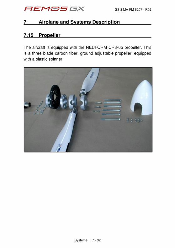
G3-8 MA FM 6207 - R02
7 Airplane and Systems Description
Systeme 7 - 32
7.15 Propeller
The aircraft is equipped with the NEUFORM CR3-65 propeller. This
is a three blade carbon fiber, ground adjustable propeller, equipped
with a plastic spinner.
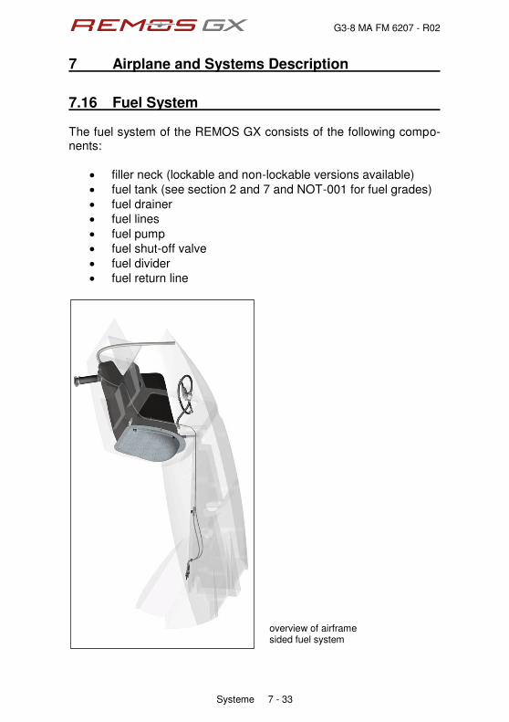
G3-8 MA FM 6207 - R02
7 Airplane and Systems Description
Systeme 7 - 33
7.16 Fuel System The fuel system of the REMOS GX consists of the following compo-nents:
‚ filler neck (lockable and non-lockable versions available)
‚ fuel tank (see section 2 and 7 and NOT-001 for fuel grades)
‚ fuel drainer
‚ fuel lines
‚ fuel pump
‚ fuel shut-off valve
‚ fuel divider
‚ fuel return line
overview of airframe sided fuel system

G3-8 MA FM 6207 - R02
7 Airplane and Systems Description
Systeme 7 - 34
fuel shut-off valve
engine sided fuel system
G3-8 MA FM 6207 - R02
7 Airplane and Systems Description
Systeme 7 - 35
Fuel is fed from the fuel tank to the electric fuel pump. This pump is a boost pump that sets the fuel system under pressure and reliably prevents and tendency for vapor lock. Through the fuel shut-off valve and the firewall the fuel is routed to-wards the fuel divider. This unit provides ports for measuring fuel pressure and fuel flow and feeds the carburetors.
NOTE
With the fuel shut-off valve closed no fuel is fed to the engine and the engine will fail due to fuel starvation. It is recommended to always keep the fuel valve open. The fuel shut-off valve is a safety item to shut off the fuel in emergency situations and need not be closed for park-ing or hangaring.
NOTE
In case of a low fuel pressure warning cross check with fuel flow. As long as fuel flow gives reasonable indica-tion, the reason for the warning is most probably found in the fuel pressure sensor or its sensing hose. Vice versa the same applies for the fuel flow sensor.
NOTE It is recommended to keep the electric fuel pump switched on during the entire flight.
NOTE Service with permitted fuel grade only and regularly drain the aircraft fuel system
For further information see maintenance manual section 12.

G3-8 MA FM 6207 - R02
7 Airplane and Systems Description
Systeme 7 - 36
7.17 Braking System The braking system of the REMOS GX consists of the following components:
‚ reservoir
‚ master cylinder
‚ parking brake valve
‚ brake lines
‚ brake cylinder, brake disc and brake pads
master cylinder with reservoir and parking brake valve
By pressing on the brake lever pressure is built up and is fed simul-taneously through the bake lines to the left and right brake cylinders. For setting the parking brake press on the brake and whilst that turn the parking brake valve.
NOTE
Once the parking brake is set, additional braking is not possible. Be sure to always apply enough brake pres-sure before setting the parking brake and never taxi with the parking brake set.
NOTE
Change brake pads early enough, otherwise the brake cylinder my slide out of its housing and the brake is damaged.
G3-8 MA FM 6207 - R02
7 Airplane and Systems Description
Systeme 7 - 37
7.18 Special Equipment and Customizing The aircraft may be equipped with special or additional equipment on ewuvqogtÓu"fgocpf0"Vjg"kpuvcnncvkqp"qh"vjku"gswkrogpv"owuv"dg"egtvi-fied and listed in the equipment list. Avionics other than those mentioned in this manual may be installed qp" ewuvqogtÓu" fgocpf0" Vjgug" cxkqpkeu" u{uvgou" oc{" tgrnceg" vjg"equipment mentioned in this manual in part or whole. The installation of this equipment must be certified and listed in the equipment list. For operating instructions please refer to the manuals belonging to the equipment installed.
NOTE
The owner of the aircraft is responsible to keep the air-craft airworthy and comply with all applicable regula-tions.

G3-8 MA FM 1208 - R06
8 Aircraft Ground Handling and Servicing
Aircraft Ground Handling and Servicing 8 - 1
Table of Content
sect. description page
8.1 Introduction 8-2
8.2 Checking and Servicing Coolant 8-2
8.3 Checking and Servicing Oil 8-3
8.4 Fuelling the aircraft 8-4
8.5 Towing 8-5
8.6 Tie-Down 8-5
8.7 Rigging a Folded Aircraft 8-6
8.8 Folding a Rigged Aircraft 8-8
8.9 Transportation of the Aircraft 8-9
8.7 Cleaning and Care 8-9

G3-8 MA FM 1208 - R06
8 Aircraft Ground Handling and Servicing
Aircraft Ground Handling and Servicing 8 - 2
8.1 Introduction This section gives guidance how to service the aircraft and how to handle it on ground. This section does not provide maintenance instructions. Maintenance procedures are defined in the maintenance manual that is specific to the individual aircraft. All maintenance shall be performed according to the REMOS Service and Maintenance Checklist, available directly at REMOS or on the website www.remos.com
8.2 Checking and Servicing Coolant The REMOS GX is designed to be easily serviceable. A flap in the upper cowling allows checking the coolant level in the overflow bottle without removing the cowling. Make sure there is app. 1 inch of coolant liquid visible in the overflow bottle. Exceeding this level is not required. For filling up cooling liquid it is required to take off the cowling. coolant BASF Glysantin Protect Plus/G48
mixing ratio 1:1 (Glysantin : water)
NOTE
Please refer to REMOS notification NOT-001 and ROTAX SI-912-016/SI-914-019 for further information on suitable engine fluids (fuel, oil, cooling liquid, additives, etc). Have a frequent look on www.flyrotax.com and on www.remos.com for the latest information.

G3-8 MA FM 1208 - R06
8 Aircraft Ground Handling and Servicing
Aircraft Ground Handling and Servicing 8 - 3
8.3 Checking and Servicing Oil The REMOS GX is designed to be easily serviceable. Access to all components which have to be lubricated or checked regularly is possible without detaching any panels. A flap in the upper cowling allows access to the oil bottle in order to check and add oil without removing the cowling. For checking the oil remove the oil tank cap. Prior to oil check turn the propeller by hand in the direction of engine rotation several times to pump oil from the engine into the oil tank. It is essential to build up compression in the combustion chamber. Maintain the pressure for a few seconds to allow the pressure flow around the piston rings into the crankcase. The speed of rotation is not important for the pressure transfer into the crankcase. This process is finished when air is returning back to the oil tank an can be noticed by a murmur from the open oil tank. The oil level should be between the minimum and maximum marking on the oil dipstick. Avoid oil levels exceeding the maximum mark as excess oil will be poured through the venting line. Fkhhgtgpeg"dgvyggp"ÐokpÑ"cpf"ÐoczÑ"octmkpi"ku"20;7"WU"swctv0
engine oil synthetic or semi-synthetic
oil rating API-SG or higher
engine oil capacity min. 2.1 qts
max. 3.1 qts
recommended oil AeroShell Sport PLUS 4 10W-40
NOTE
Please refer to REMOS notification NOT-001 and ROTAX SI-912-016/SI-914-019 for further information on suitable engine fluids (fuel, oil, cooling liquid, additives, etc). Have a frequent look on www.flyrotax.com and on www.remos.com for the latest information.
G3-8 MA FM 1208 - R06
8 Aircraft Ground Handling and Servicing
Aircraft Ground Handling and Servicing 8 - 4
8.4 Fuelling the Aircraft The fuel filler cap is located on the right-hand side of the fuselage behind the wing. After removing the lockable fuel filler cap, refuelling is easily possible. Aircraft up to SN377 must be fuelled very carefully in order to prevent spilling of fuel. From SN378 on the fuel system has been modified to allow more rapid refuelling without spilling. The fuel tank vent line is also the overflow line and is located on the belly of the airplane. If the fuel tank is full (recognizable by the fuel nozzle shutting down), further filling of the tank will lead the fuel to overflow. The fuel tank is equipped with a sight tube to check fuel level. The sight tube can be found inside the cabin between the two seats.
usable fuel quantity 21 US gallons
total fuel quantity 22 US gallons
fuel qualities AVGAS, MOGAS or min. AKI 91, ideally free of ethanol
NOTE
Please refer to REMOS notification NOT-001 and ROTAX SI-912-016/SI-914-019 for further information on suitable engine fluids (fuel, oil, cooling liquid, additives, etc). Have a frequent look on www.flyrotax.com and on www.remos.com for the latest information.

G3-8 MA FM 1208 - R06
8 Aircraft Ground Handling and Servicing
Aircraft Ground Handling and Servicing 8 - 5
8.5 Towing Due to the low weight of the REMOS GX, it is very easy to move the cktetchv" d{" jcpf" qp" vjg" itqwpf0" VjcvÓu" yj{" vjgtg" ku" pq" urgekcn"equipment for towing provided. Do not attempt under any circumstances to tow the aircraft by attaching any kind of towing equipment to the nose wheel! Grab the aircraft at the propeller roots just outside the spinner to pull it forward. For pushing the aircraft backward it is recommended to push at the root of the horizontal tail. Bushing backward is also permitted at the strut. If this is done with open doors, one can grab the rudder pedal to steer backward.
8.6 Tie-Down To tie down the aircraft we recommend the use of at least three ropes (left wing, right wing, and tail). Tie down each wing by attaching the rope to the lug located on the upper strut bracket. Another rope connection point is provided on the tail skid of the aircraft. When necessary, a fourth rope can be slid around the propeller/gear drive shaft at the nose of the aircraft. Aircrafts from SN380 are equipped with a metric M8 thread on the lower side of the wing near the wingtips and are provided with bolt-in lugs. If required, bolt in the lugs and tie down the aircraft there. Do not fly with the tie-down lugs installed! An additional rope may be applied to the propeller. Wrap the rope around the spacer between spinner and prop flange of the engine, accessible through the gap between cowling and spinner. In order to avoid damages to the spinner do not wrap the rope around the prop blade roots. Secure the control stick by use of the safety belt to prevent the control surfaces from being slammed from stop to stop by the wind.
NOTE The maximum wind velocity to leave a tied down aircraft in the open is 38 kts.
G3-8 MA FM 1208 - R06
8 Aircraft Ground Handling and Servicing
Aircraft Ground Handling and Servicing 8 - 6
8.7 Rigging a Folded Aircraft The REMOS GX is manufactured to the highest quality standards. All components are very precise and provide the maximum aerodynamic quality. It is therefore strongly recommended that you be very careful when assembling or disassembling components such as the wings, stabilizer and other parts. The following instructions will provide you with all the necessary information.
NOTE
Folding or unfolding the wings and attaching or detaching the horizontal tail is a two person procedure. Do not to try this alone. Severe damage to the aircraft may result.
Tools, equipment and preparation
‚ bolt release tool (provided with the aircraft)
‚ screwdriver (Philips head)
‚ grease for bolts
‚ place the stabilizer behind the aircraft protective support
‚ remove both stabilizer bolts from their bushings
‚ remove both wing bolts from their bushings

G3-8 MA FM 1208 - R06
8 Aircraft Ground Handling and Servicing
Aircraft Ground Handling and Servicing 8 - 7
Connecting folded wings to the fuselage
1. Unlock the fairings between the strut and the wing/fuselage and slide them along the strut.
2. Withdraw the main wing securing bolt from the wing and place it nearby. Ensure that the bolt stays clean until remounted.
3. Remove the wing support aid bracket while a second person supports the wing at the wing tip.
4. Now the second person at the wing tip moves the wing slowly forward while ensuring that the wing does not spin around its axis. The weight of the wing is supported by its strut, therefore, the wing must never be lifted or pushed down from the top.
5. When the wing has reached its maximum forward position, the person at the fuselage position must rotate the wing to align both connection latches. Care must be taken that the surface of the wing is not damaged by the fuselage connecting latches.
6. When the connecting latches between the fuselage and wing are aligned, the wing must be lifted by the person at the wing tip. The person at the fuselage must ensure that the flap drive connection fits correctly into the bushing on the fuselage.
7. If all latches have engaged and the wing fits properly to the fuselage, the main bolt can be pushed into its support tube. To install the main bolt correctly, please use the special installation tool which comes with the aircraft. Now secure the bolt with the securing pin. The person at the wing tip can now release the pressure supporting the wing tip.
8. Inside the cabin, the pushrod quick fasteners MUST properly be connected and secured.
Insecure connection, improper operation of control surfaces or insecurely locked fasteners will lead to loss of control of the aircraft!! When in doubt contact your local REMOS dealer or service center.
9. Proceed in the same order with the second wing.
G3-8 MA FM 1208 - R06
8 Aircraft Ground Handling and Servicing
Aircraft Ground Handling and Servicing 8 - 8
Installing the horizontal tail
1. Hold the horizontal tail in place so that the bushings in the fuselage match up with those in the horizontal tail.
2. Apply the attachment bolts from left to right into their bushings. The forward bolt is marked by a "V", the rearward bolt by "H".
3. Align the hole of the attachment bolt with the one in the right bushing and secure the bolts with Fokker needles.
4. Connect the cable plug for the electric trim actuator
5. The pushrod quick fasteners MUST be connected properly and secured.
Insecure connection, improper operation of control surfaces or insecurely locked fasteners will lead to loss of control of the aircraft!! When in doubt contact your local REMOS dealer or service center.
6. Attach the tail cover and secure it with the screws provided. Connect the electric jack for the taillight.
After rigging the aircraft perform a preflight check.
8.8 Folding a Rigged Aircraft To disassemble the aircraft, perform the above described procedures in reverse order.

G3-8 MA FM 1208 - R06
8 Aircraft Ground Handling and Servicing
Aircraft Ground Handling and Servicing 8 - 9
8.9 Transportation of the Aircraft If you intend to store the aircraft with the wings folded, we recommend using REMOS folding wing supports (ask your local dealer). With these supports mounted, the wings are secured properly and handling of the aircraft will be much easier. When the aircraft has to be moved by trailer, please ask your authorized REMOS dealer for advice. When placed on a trailer in a wrong way, serious damage could result.
8.10 Cleaning and Care After every day of flight, it is recommended that you clean the surface of the aircraft using pure water and a soft cotton towel only. Take special care when cleaning the windows to use lots of water to loosen and rinse away bugs and dirt and use with only a soft cotton towel, or otherwise you will create scratches. If cleaned regularly, you may not need to use any special cleaning products. If for any reason special cleaning products need to be used, please contact your dealer for advice. For polishing you can use almost any car polish but be sure that no silicone is used in that product.

G3-8 MA FM 1208 - R06
Imprint
Pilot Operating Handbook REMOS GX
ASTM Edition
Copyright REMOS AG © REMOS 2007-2015, all rights reserved

POH Supplement Î Flight Training

G3-8 MA FM 1209 Î R06
Supplement Flight Training
Supplement Flight Training 9 - 1
Table of Content
sect. description page
1 Introduction 9-2
2 Take-Off 9-3
3 Climb 9-4
4 Cruise 9-5
5 Stall 9-6
6 Slip 9-7
7 Glide 9-8
8 Descent 9-9
9 Approach 9-10
10 Touch Down 9-12

G3-8 MA FM 1209 Î R06
1 Introduction
Supplement Flight Training 9 - 2
This chapter should enable you to familiarize yourself with the flight performance and flight characteristics of the REMOS GX. To complete these instructions, please refer to the appropriate sections in the POH.
The following pages describe flight characteristics experienced during various flight configurations and weather conditions:
‚ Take-off
‚ Climb
‚ Cruise
‚ Stall
‚ Slip
‚ Glide ‚ Descent
‚ Approach
‚ Touch down
NOTE
This chapter was introduced as an additional guide to experience the capabilities of the aircraft, It is not a substitute for flight school training! If you are not yet familiar with the aircraft, we strongly recommend that you follow these instructions only when accompanied by a skilled flight instructor.
G3-8 MA FM 1209 Î R06
2 Take-Off
Supplement Flight Training 9 - 3
Take-off under normal conditions
1. After the pre-flight check has been completed, extend flaps to 15°. Take-off may be performed without flaps, too, but this leads to higher take-off distances.
2. Ensure that the elevator trim is in the correct position.
3. Whenever possible, take-off directly into the wind. The maximum demonstrated crosswind component is 15 kts.
4. Smoothly apply full throttle (fully forward) and maintain runway heading.
5. As the aircraft accelerates, gently pull back on the control stick to raise the nose slightly until the aircraft becomes airborne at about VLO = 50 kIAS (58 mph IAS).
6. Once airborne, slowly release the back pressure on the control stick to allow the airspeed to increase to VY Flaps 15 = 58 kIAS (67 mph IAS). Maintain this speed and avoid making any climbing turns until a sufficiently safe altitude has been reached.
7. When at safe altitude, retract the flaps (if they were deployed) and accelerate to VY clean = 60 kIAS (69 mph IAS).
Take-off under tailwind conditions
Similar to normal take-off except that the take-off distance will be extended. Ensure that you determine the take-off distance required to ensure you have sufficient runway length prior to take-off. Take-Off in rain or with a dirty aircraft
Surface conditions, high density altitude and temperatures, raindrops and bugs affect the performance of the aircraft. Be aware that in these conditions the performance figures will not meet the published figures, as they apply to a clean aircraft under standard atmospheric conditions. Expect a significant drop in performance.
G3-8 MA FM 1209 Î R06
3 Climb
Supplement Flight Training 9 - 4
Climb with Best Angle of Climb
With engine set to full power, establish VX, which is VX Flaps 15 = 39 kIAS (45 mph IAS) for flaps 15 deg and VX clean = 51 kIAS (59 mph IAS) with flaps up. At this airspeed the aircraft will achieve the steepest angle of climb. During climb it is essential to monitor oil and water (CHT) temperatures. Adjust the oil temperature regulation flap as required. Climb with Best Rate of Climb
With engine set to full power, establish VY, which is VY Flaps 15 = 58 kIAS (67 mph IAS) for flaps 15 deg and VY clean = 60 kIAS (69 mph IAS) with flaps up. At this airspeed the aircraft will achieve the best rate of climb. During climb it is essential to monitor oil and water (CHT) temperatures. Adjust the oil temperature regulation flap as required. Climb while in cruise
If you wish to climb in cruise, select an airspeed between 70 to 80 kIAS (80 to 90 mph IAS). At these speeds, the aircraft will climb between slower than best rate of climb due to the higher airspeed.
NOTE
It is strongly recommended that you monitor oil and water (CHT) temperatures. Under no circumstances should any of the engine temperature limits be exceeded, otherwise, an engine failure may result.
Climb in rain or with a dirty aircraft
Raindrops and bugs affect the performance of the aircraft. Be aware that in these conditions the performance figures will not meet the published figures, as they apply for a clean aircraft under standard atmospheric conditions. Expect a performance loss of 10% to15%.
G3-8 MA FM 1209 Î R06
4 Cruise
Supplement Flight Training 9 - 5
Normal cruise
An economical cruise is flown at engine speeds of 4,400 RPM to 4,800 RPM. With the Sensenich or Neuform propeller this will result in airspeeds between 98mph (85kts) and 111mph (97kts) with a fuel flow between 4 and 5 gph High speed cruise is done with engine speeds between 5,000 RPM and 5,400 RPM. With the Sensenich or Neuform propeller this will result in airspeeds between 117mph (102kts) and 130mph (113kts) with a fuel flow between 5 and 7 gph. If required, the aircraft is capable of achieving an airspeed up to 137 mph (119 kts) at full power settings. If doing so, always monitor the engine speed. The maximum continuous engine speed is 5,500 RPM and may only be sustained for 5 minutes. Do not exceed the maximum engine speed of 5,800 RPM. Cruise in gusty conditions
When flying in gusty weather conditions, the normal operating airspeed VNO = 107 kIAS = 123 mph IAS should not be exceeded for safety reasons. The REMOS GX offers very stable flight characteristics even in heavy weather conditions. Cruise in rain or with dirty aircraft
Raindrops and bugs affect the performance of the aircraft. Be aware that in these conditions the performance figures will not meet the published figures, as they apply for a clean aircraft under standard atmospheric conditions. Expect a performance loss of 10% to15%. When flying in rain always activate the carburetor heat.

G3-8 MA FM 1209 Î R06
5 Stall
Supplement Flight Training 9 - 6
The REMOS GX is fully controllable when flying at a wide range of airspeeds. At airspeeds below the lower speed limit, the aircraft will display very stable stall characteristics. If the airspeed is reduced by the pilot gradually pulling back on the control stick, aerodynamic buffet will occur, indicating that the aircraft is approaching the stall speed. Should the aircraft then be allowed to stall, the aircraft still will remain controllable. The aircraft can be stalled with flaps both extended or retracted. Conducting a stall maneuver does not require special skills. However, if you are not yet familiar with the aircraft, we recommend you do this exercise only when accompanied by an experienced flight instructor.

G3-8 MA FM 1209 Î R06
6 Slip
Supplement Flight Training 9 - 7
The slip is a very stable flight condition and is also very easy to perform. This maneuver is used to increase aerodynamic drag to enable a high rate of descent. Before establishing a slip, you have to ensure that the airspeed is within the required limits. The maximum maneuvering speed VA = 88 kIAS (101 mph IAS) should not be exceeded. If performing a slip with flaps extended, a maximum indicated airspeed of VFE= 78 kIAS (90 mph IAS) must be maintained. You will achieve the maximum rate of descent when slipping with flaps fully extended and flying at VFE. Conducting a slip does not require special skills. However, if you are not yet familiar with the aircraft, we recommend to do this exercise only when accompanied by an experienced flight instructor.
G3-8 MA FM 1209 Î R06
7 Gliding
Supplement Flight Training 9 - 8
The aircraft can glide well with the engine off. Best glide ratios are achieved within an indicated airspeed of 60 kIAS (69 mph IAS). These speeds will establish a glide ratio of about 1:10 with the flaps retracted (0° position).

G3-8 MA FM 1209 Î R06
8 Descent
Supplement Flight Training 9 - 9
When descending from level flight it is important to monitor engine temperatures. During descent, the temperatures will decrease, which could cause engine failure or carburetor icing to develop. Therefore we strongly recommend that you not exceed the lower limits of these temperatures. Engage carburetor heat before beginning the descent.

G3-8 MA FM 1209 Î R06
9 Approach
Supplement Flight Training 9 - 10
Approach under normal conditions
Always land on the most suitable runway, taking into consideration wind direction, length of runway, obstacles on the approach, etc. It is recommended to fly the approach at 60 kIAS (69 mph IAS). The recommended target airspeed (airspeed on short final in app. 50ft altitude) for approach at MTOW is 55 kIAS (63 mph IAS). Approach under tailwind conditions
When on final approach with a tailwind component, the REMOS GX does not require different approach or flare procedures than those used in calm or headwind conditions. However, you do have to keep in mind that the landing distance will increase significantly. Approach in crosswind conditions
Crosswinds do not have a big effect on the flight characteristics of the REMOS GX, as long as the cross-wind component stays within the maximum demonstrated speed of up to 15 kts. Performing a crosswind landing does not require above-average piloting skills. Nevertheless, if not yet familiar with the aircraft, we recommend that you perform crosswind landings only when accompanied by an experienced flight instructor until sufficient experience has been gained. Approach in turbulent weather conditions
It is recommended to fly the approach at 60 kIAS (69 mph IAS). The recommended target airspeed (airspeed on short final in app. 50ft altitude) for approach at MTOW is 55 kIAS (63 mph IAS). This will give you a reserve airspeed to balance any unexpected deviations in altitude and heading. In more gusty conditions it may be beneficial to stabilize the glide slope by keeping the flap setting to the 15° position.

G3-8 MA FM 1209 Î R06
9 Approach
Supplement Flight Training 9 - 11
Approach in rain showers
Raindrops on the wing surfaces influence the aerodynamic characteristics of the airfoil; drag will increase while lift decreases. The airfoil used on the REMOS GX features stable flight characteristics in rainy conditions. Therefore, there are no special advisories for flights within rain. we recommend that you operate the aircraft as you would in turbulent weather conditions (see "Approach in turbulent weather conditions). When flying in rain always activate the carburetor heat. Approach in the slip configuration
If a high descent rate is required on final, we recommend that you conduct a slip maneuver. Conducting an approach in the slip configuration does not require special skills, however, if you are not yet familiar with the aircraft we recommend that yo do this exercise only when accompanied by an experienced flight instructor.
G3-8 MA FM 1209 Î R06
10 Touchdown
Supplement Flight Training 9 - 12
The aircraft has very good low speed characteristics and so is very controllable all the way through the landing phase. After a good approach has been conducted, the REMOS GX does not require much action to land with a perfect touch down. It is important to establish a safe and stable airspeed during the approach.

G3-8 MA FM 1209 Î R06
Imprint
Pilot Operating Handbook REMOS GX Supplement Flight Training
ASTM Edition
Copyright REMOS AG © REMOS 2007-2015, all rights reserved

POH Supplement Î Glider Towing

G3-8 MA FM 1210 - R06
Supplement Glider Towing
Supplement Glider Towing 10 - 1
Table of Content
sect. description page
1 General Information 10-2
2 Operating Limitations 10-3
3 Emergency Procedures 10-5
4 Normal Procedures 10-7
5 Performance 10-10
6 Weight and Balance 10-16
7 Systems 10-17
8 Aircraft Ground Handling and Service 10-18

G3-8 MA FM 1210 - R06
1 General Information
Supplement Glider Towing 10 - 2
1.1 Introduction This supplement is to be used only in addition to the REMOS GX Pilot Operating Handbook!
1.2 Certification The REMOS GX is manufactured in compliance with the rules of the Light Sport Aircraft airworthiness standards and does not conform to standard category airworthiness requirements.
1.3 Quick Reference For use as a glider towing aircraft, the REMOS GX is equipped with the TOST E85 tow release clutch, which is connected to the fuselage tail by a specially developed mounting frame. To release the tow rope a release lever is located on the left hand side of the pilot seat (colored yellow). Additionally, a rear view mirror must be installed inside the aircraft, above the pilot seat.

G3-8 MA FM 1210 - R06
2 Operating Limitations
Supplement Glider Towing 10 - 3
2.1 Towing Speed max. towing speed VT of glider min. towing speed 1,3VS1 of glider, at least 53 kIAS = 61 mph IAS
2.2 Tow Ropes length of tow rope 130 to 200 ft weak link max. 300 dN
2.3 Maximum Glider Take-Off Weight The maximum permissible take-off weight of the glider to be towed varies with the propeller mounted to the REMOS GX. The following operating limitations may not be exceeded: Propeller Glider
Tonini GT-2 1,210 lb [550kg]
Woodcom SR38+1 1,210 lb [550kg]
Sensenich R70EN 1,580 lb [720kg]
Neuform CR3-65 1,580 lb [720kg]
Rospeller 1,430 lb [650kg]
2.4 Crew During glider towing operations the REMOS GX must be operated only by one pilot (no passenger allowed, except for training/instruction). In all cases, the total take-off weight (towing aircraft + glider) must not exceed 2,900 lb.

G3-8 MA FM 1210 - R06
2 Operating Limitations
Supplement Glider Towing 10 - 4
2.5 Minimum Equipment List
‚ as per D-VFR minimum equipment list, plus
‚ TOST tow release clutch type E85
‚ REMOS mounting frame for tow release clutch
‚ yellow colored release handle
‚ rear view mirror placed on main spar carrythrough
2.6 Flying Without Doors not permitted during towing operations
2.7 Required Placards and Markings Adjacent to the airspeed indicator: Adjacent to the tow release handle: At the release clutch bracket:

G3-8 MA FM 1210 - R06
3 Emergency Procedures
Supplement Glider Towing 10 - 5
3.1 Engine Failure Procedure
Case 1: altitude not enough for engine re-start
1. AVIATE Î NAVIGATE Î COMMUNICATE
2. landing site IDENTIFY
3. glider pilot NOTIFIED
4. glider pilot RELEASE ROPE
5. engine OFF
6. fuel valve CLOSE
7. declare emergency MAYDAY MAYDAY MAYDAY
8. master switch OFF
9. safety belts TIGHTEN
10. tow rope RELEASE
11. emergency landing APPROPRIATE TERRAIN
Case 2: altitude sufficient for engine re-start
1. AVIATE Î NAVIGATE Î COMMUNICATE
2. landing site IDENTIFY
3. glider pilot NOTIFIED
4. glider pilot RELEASE ROPE
5. carburetor heat PULL
6. electric fuel pump ON
7. choke OFF
8. starter ENGAGE
9. if engine does not start continue with case 1
10. if engine starts, continue flight and land on an airfield

G3-8 MA FM 1210 - R06
3 Emergency Procedures
Supplement Glider Towing 10 - 6
3.2 Abnormal Flight Attitude Procedure
1. AVIATE Î NAVIGATE Î COMMUNICATE
2. glider pilot NOTIFIED
3. engine REDUCE POWER
4. glider pilot RELEASE ROPE
5. recover gently and return to an airfield
NOTE
If the glider pilot cannot recover from the abnormal flight attitude and does not or cannot release the tow rope, the REMOS GX pilot must release the tow rope to recover from the abnormal flight attitude.
NOTE
If the abnormal flight attitude cannot be recovered from at all, the tow rope cannot be released, or the weak link does not break, activate the recovery system.
3.3 Failure of the Release Clutch Procedure
1. approach airspeed VAPP = 60 kIAS = 69 mph IAS
2. full flaps airspeed VFE = 78 kIAS = 90 mph IAS
3. flaps DOWN
4. variable pitch prop 5,600 rpm
5. engine power AS REQUIRED
6. elevator trim AS REQUIRED
7. electrical fuel pump ON
8. touchdown on main wheels first with elevator fully held back.
NOTE
The rope will hang down significantly from the aircraft due to its own weight. Therefore it can become tangled with obstacles, plants, wires, vehicles, persons, etc.

G3-8 MA FM 1210 - R06
4 Normal Procedures
Supplement Glider Towing 10 - 7
4.1 Preflight Check Checklist
1. Perform standard preflight check
2. Check tow release clutch and test-release a tow rope
4.2 Take-Off Procedure
1. oil cooler flap OPEN
2. carburetor heat OFF
3. electric fuel pump ON
4. landing light RECOMMENDED
5. flaps 15 degrees
6. elevator trim 2/3 UP
7. rudder and aileron NEUTRAL
8. variable pitch prop 5,600 rpm
9. taxi forward ROPE STRAIGHT
10. engine power FULL POWER
11. rotate VR = 45 kIAS = 52 mph IAS
12. lift-off VLO = 50 kIAS = 58 mph IAS
13. best climb VY Flaps 15 = 58 kIAS = 67 mph IAS
14. flaps RETRACT
NOTE
During take-off, special care must be taken that the climb rate and airspeed are compatible with the required values of the towed glider. Watch your rate of climb immediately after take-off (do not gzeggf" vjg" inkfgtÓu"climb capability).
NOTE
To maintain permissible water and oil temperatures during climb and descent, the aircraft must be equipped with an oil temperature regulation flap. During climb the operating lever of this flap should be in the "open/cooler" position.

G3-8 MA FM 1210 - R06
4 Normal Procedures
Supplement Glider Towing 10 - 8
4.3 Climb Briefing Flight tests have been conducted with various glider airplanes. These tests revealed that modern composite gliders, especially when loaded with water ballast, must be towed faster than older wooden sailplanes. The modern gliders are usually towed with airspeeds of 75 mph = 65 kts or possibly above that with flaps retracted. Older sailplanes can be towed with airspeeds as low as 48 mph = 56 kts; in that case select the 15 degrees flap setting.
4.4 Descent Checklist
1. flaps CLEAN
2. engine speed AS REQUIRED
3. electric fuel pump ON
4. maneuvering speed VA = 88 kIAS = 101 mph IAS
5. normal operating speed VNO = 107 kIAS = 123 mph IAS
6. never exceed speed VNE = 135 kIAS = 155 mph IAS
7. max. cont. engine speed 5,500 rpm
8. carburetor heat RECOMMENDED
9. landing light RECOMMENDED
10. oil cooler flap AS REQUIRED
11. CHT max. 275°F = 135°C
12. oil temperature 342È488̇H"?"72È352̇E
NOTE
Special care must be taken to keep all temperatures within the permissible range. To keep temperatures within the proper operation levels, the throttle may be left at a setting just above the idle position. Do not allow the oil temperature to drop rapidly.
G3-8 MA FM 1210 - R06
4 Normal Procedures
Supplement Glider Towing 10 - 9
4.5 Approach Briefing
1. wind, weather, visibility OK
2. ATIS CHECKED
3. runway CORRECT DIRECTION
4. traffic circuit ALTITUDE and ROUTING
5. radios ON and FREQUENCY SET
6. transponder AS REQUIRED
7. full flaps BELOW 81 mph = 70kts
8. airspeed in pattern 80..110 kIAS = 95..125 mph IAS
9. approach airspeed VAPP = 60 kIAS = 69 mph IAS
4.6 Landing Procedure
1. full flaps airspeed VFE = 78 kIAS = 90 mph IAS
2. approach airspeed VAPP = 60 kIAS = 69 mph IAS
3. target airspeed VT = 50 kIAS = 58 mph IAS
4. flaps DOWN
5. landing light RECOMMENDED
6. variable pitch prop 5,600 rpm
7. engine power AS REQUIRED
8. elevator trim AS REQUIRED
9. electric fuel pump ON
10. carburetor heat RECOMMENDED
11. oil cooler flap AS REQUIRED
12. CHT max. 275°F = 135°C
13. oil temperature 120 to 266°F = 50 to 130°C
14. tow rope RELEASE ON THRESHOLD
15. touchdown on main wheels first with elevator fully held back.
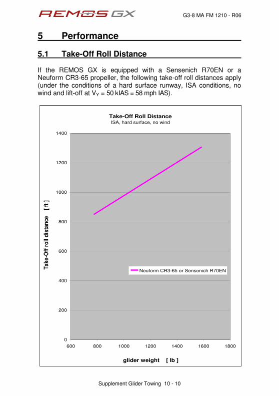
G3-8 MA FM 1210 - R06
5 Performance
Supplement Glider Towing 10 - 10
5.1 Take-Off Roll Distance If the REMOS GX is equipped with a Sensenich R70EN or a Neuform CR3-65 propeller, the following take-off roll distances apply (under the conditions of a hard surface runway, ISA conditions, no wind and lift-off at VY = 50 kIAS = 58 mph IAS).
Take-Off Roll DistanceISA, hard surface, no wind
0
200
400
600
800
1000
1200
1400
600 800 1000 1200 1400 1600 1800
glider weight [ lb ]
Take-O
ff r
oll
dis
tan
ce
[
ft ]
Neuform CR3-65 or Sensenich R70EN
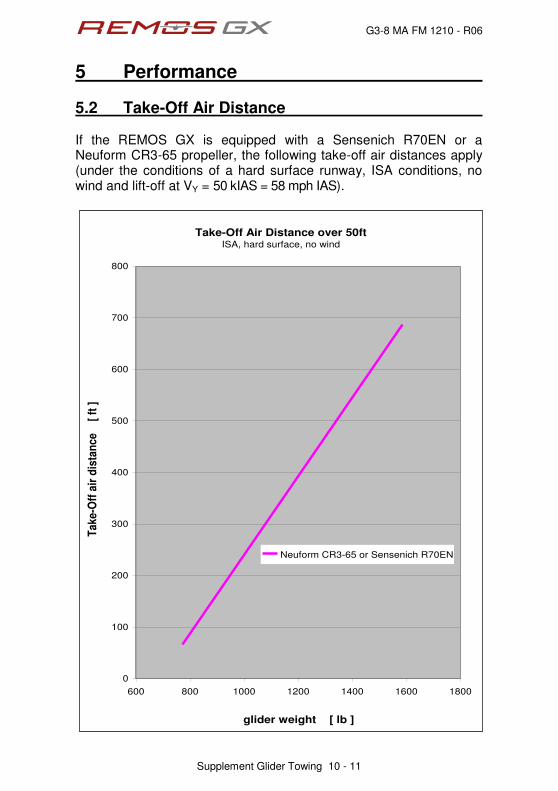
G3-8 MA FM 1210 - R06
5 Performance
Supplement Glider Towing 10 - 11
5.2 Take-Off Air Distance If the REMOS GX is equipped with a Sensenich R70EN or a Neuform CR3-65 propeller, the following take-off air distances apply (under the conditions of a hard surface runway, ISA conditions, no wind and lift-off at VY = 50 kIAS = 58 mph IAS).
Take-Off Air Distance over 50ftISA, hard surface, no wind
0
100
200
300
400
500
600
700
800
600 800 1000 1200 1400 1600 1800
glider weight [ lb ]
Take-O
ff a
ir d
ista
nce
[
ft ]
Neuform CR3-65 or Sensenich R70EN
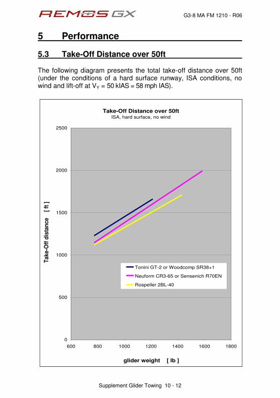
G3-8 MA FM 1210 - R06
5 Performance
Supplement Glider Towing 10 - 12
5.3 Take-Off Distance over 50ft The following diagram presents the total take-off distance over 50ft (under the conditions of a hard surface runway, ISA conditions, no wind and lift-off at VY = 50 kIAS = 58 mph IAS).
Take-Off Distance over 50ftISA, hard surface, no wind
0
500
1000
1500
2000
2500
600 800 1000 1200 1400 1600 1800
glider weight [ lb ]
Ta
ke
-Off
dis
tan
ce
[ ft
]
Tonini GT-2 or Woodcomp SR38+1
Neuform CR3-65 or Sensenich R70EN
Rospeller 2BL-40
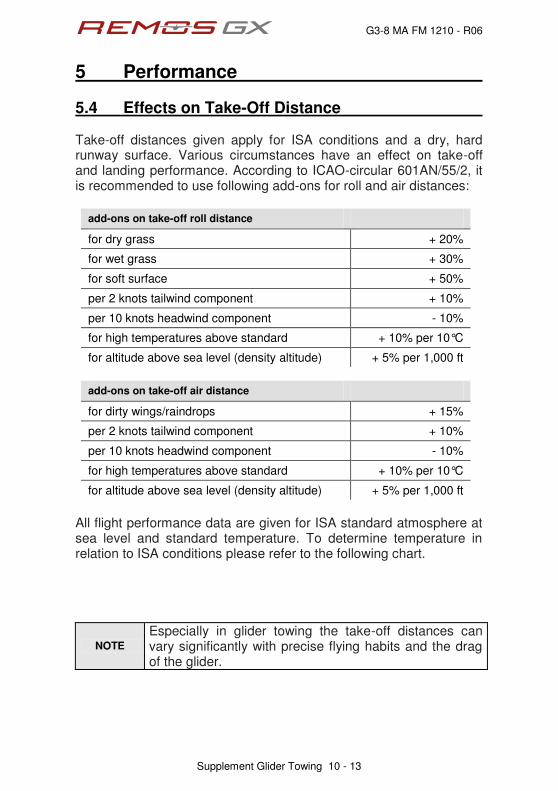
G3-8 MA FM 1210 - R06
5 Performance
Supplement Glider Towing 10 - 13
5.4 Effects on Take-Off Distance Take-off distances given apply for ISA conditions and a dry, hard runway surface. Various circumstances have an effect on take-off and landing performance. According to ICAO-circular 601AN/55/2, it is recommended to use following add-ons for roll and air distances:
add-ons on take-off roll distance
for dry grass + 20%
for wet grass + 30%
for soft surface + 50%
per 2 knots tailwind component + 10%
per 10 knots headwind component - 10%
for high temperatures above standard + 10% per 10°C
for altitude above sea level (density altitude) + 5% per 1,000 ft
add-ons on take-off air distance
for dirty wings/raindrops + 15%
per 2 knots tailwind component + 10%
per 10 knots headwind component - 10%
for high temperatures above standard + 10% per 10°C
for altitude above sea level (density altitude) + 5% per 1,000 ft
All flight performance data are given for ISA standard atmosphere at sea level and standard temperature. To determine temperature in relation to ISA conditions please refer to the following chart.
NOTE
Especially in glider towing the take-off distances can vary significantly with precise flying habits and the drag of the glider.

G3-8 MA FM 1210 - R06
5 Performance
Supplement Glider Towing 10 - 14
ISA std. Temperature
0
1000
2000
3000
4000
5000
6000
7000
8000
9000
10000
11000
12000
13000
14000
15000
-15 -10 -5 0 5 10 15
temperature [ °C ]
pre
ssu
re a
ltit
ud
e
[
ft ]
G3-8 MA FM 1210 - R06
5 Performance
Supplement Glider Towing 10 - 15
5.5 Tested Glider Configuration The following gliders have been towed during flight tests: LS-1, LS-4, Baby-III, Astir and Twin Astir, Hornbach, Junior, Jantar, Pirat, Puchacz, Discus and DuoDiscus, Blanik, DG-100/300/500, DG-1000, ASK-21 and ASW-24, Nimbus and Cirrus, Cobra, PIK-20.
5.6 Remarks Based on the rules of the Light Sport Aircraft airworthiness standards, the maximum dimension is defined by the weight of the glider to be towed, without consideration of glider aerodynamics. During the flight test with the DG-1000T, a maximum permissible glider weight of 1,580 lb has been demonstrated. For gliders with a maximum permissible glider weight of 1,580lb, but less favourable aerodynamics than the DG-1000T, a lower climb rate and significantly longer take-off distance are to be expected.
NOTE
Inexperienced pilots should start with a one person lightweight glider and increase the glider weight step by step.

G3-8 MA FM 1210 - R06
6 Weight and Balance
Supplement Glider Towing 10 - 16
6.1 General When the aircraft is used for glider towing, the weight and balance calculations for the standard configuration are valid also for towing operations. Concerning payload, there are some restrictions which have to be observed, see also Section 3 within this supplement.
6.2 Required Equipment The following additional equipment is required to use aircraft the for glider towing, and must be taken into account in the weight and balance:
‚ TOST tow release clutch, type E 85
‚ REMOS mounting frame for tow release clutch
‚ release handle (colour yellow)
‚ REMOS oil temperature regulation flap
‚ rear view mirror The following equipment is not part of the center of gravity calculation, but is also necessary for glider towing:
‚ towing rope with ring connector
‚ weak link 300 daN (green)
NOTE
The pilot has to ensure that the required weak link is attached to the tow rope; otherwise the structure of the aircraft may become overloaded!

G3-8 MA FM 1210 - R06
7 Systems
Supplement Glider Towing 10 - 17
The tow release handle is installed inside the cabin of the REMOS GX. The handle is located on the left hand side of the pilot seat, colored yellow. Pulling the handle releases the tow rope. The handle should provide a free play of 1/2 to 1 Inch.
G3-8 MA FM 1210 - R06
8 Aircraft Ground Handling and Service
Supplement Glider Towing 10 - 18
During regular servicing intervals, the tow release clutch must be cleaned, lubricated and checked to assure proper operation. A general overhaul of the release clutch must be conducted every 4 years or 4,000 towing operations, whatever comes first. For further kphqtocvkqp" tghgt" vq" vjg" ugrctcvg" qrgtcvqtÓu" ocpwcn" qh" vjg"manufacturer.

G3-8 MA FM 1210 - R06
Imprint
Pilot Operating Handbook REMOS GX Supplement Glider Towing
ASTM Edition
Copyright REMOS AG © REMOS 2007-2015, all rights reserved

POH Supplement Î Banner Towing
G3-8 MA FM 1211 - R03
Supplement Banner Towing
Supplement Glider Towing 11 - 1
Table of Content
sect. description page
1 General Information 11-2
2 Operating Limitations 11-3
3 Emergency Procedures 11-5
4 Normal Procedures 11-7
5 Performance 11-9
6 Weight and Balance 11-12
7 Systems 11-13
8 Aircraft Ground Handling and Service 11-14
G3-8 MA FM 1211 - 02
1 General Information
Supplement Glider Towing 11 - 2
1.1 Introduction This supplement is to be used only in addition to the REMOS GX Pilot Operating Handbook!
1.2 Certification The REMOS GX is manufactured in compliance with the rules of the Light Sport Aircraft airworthiness standards and does not conform to standard category airworthiness requirements.
1.3 Quick Reference For use as a banner towing aircraft, the REMOS GX is equipped with the TOST E85 tow release clutch, which is connected to the fuselage tail by a specially developed mounting frame. To release the tow rope a release lever is located on the left hand side of the pilot seat (colored yellow). Additionally, a rear view mirror must be installed inside the aircraft, above the pilot seat.

G3-8 MA FM 1211 - 02
2 Operating Limitations
Supplement Glider Towing 11 - 3
2.1 Towing Speed max. towing speed 65 kIAS = 75 mph IAS
2.2 Tow Ropes length of tow rope 130 to 200 ft weak link max. 300 dN
2.3 Banner When towing banners the drag of the banner is relevant and not its size. Low drag banners up to 216m
2 have been tested.
max. drag 700 N at 73 kCAS weak weight 20 kg Approved banners should be used.
2.4 Crew During banner towing operations the REMOS GX must be operated only by one pilot (no passenger allowed, except for training/instruction).
2.5 Minimum Equipment List
‚ as per D-VFR minimum equipment list, plus
‚ TOST tow release clutch type E85
‚ REMOS mounting frame for tow release clutch
‚ yellow colored release handle
‚ rear view mirror placed on main spar carrythrough

G3-8 MA FM 1211 - 02
2 Operating Limitations
Supplement Glider Towing 11 - 4
2.6 Flying Without Doors not permitted during towing operations
2.7 Required Placards and Markings Adjacent to the airspeed indicator: Adjacent to the tow release handle: At the release clutch bracket:

G3-8 MA FM 1211 - 02
3 Emergency Procedures
Supplement Glider Towing 11 - 5
3.1 Engine Failure Procedure
Case 1: altitude not enough for engine re-start
1. AVIATE Î NAVIGATE Î COMMUNICATE
2. landing site IDENTIFY
3. engine OFF
4. fuel valve CLOSE
5. declare emergency MAYDAY MAYDAY MAYDAY
6. master switch OFF
7. safety belts TIGHTEN
8. tow rope RELEASE
9. emergency landing APPROPRIATE TERRAIN
10. banner RELEASE BEFORE LANDING
Case 2: altitude sufficient for engine re-start
1. AVIATE Î NAVIGATE Î COMMUNICATE
2. landing site IDENTIFY
3. carburetor heat PULL
4. electric fuel pump ON
5. choke OFF
6. starter ENGAGE
7. if engine does not start continue with case 1
8. if engine starts, continue flight and land on an airfield

G3-8 MA FM 1211 - 02
3 Emergency Procedures
Supplement Glider Towing 11 - 6
3.2 Failure of the Release Clutch Procedure
1. approach airspeed VAPP = 60 kIAS = 69 mph IAS
2. full flaps airspeed VFE = 78 kIAS = 90 mph IAS
3. max. airspeed with banner VNE banner = 65 kIAS = 75 mph IAS
4. flaps DOWN
5. engine power AS REQUIRED
6. elevator trim AS REQUIRED
7. electrical fuel pump ON
8. touchdown on main wheels first with elevator fully held back.
NOTE
The banner will hang down significantly from the aircraft due to its own weight. Therefore it can become tangled with obstacles, plants, wires, vehicles, persons, etc. Keep the approach as steep as possible so that banner and aircraft are on the ground at the same time.

G3-8 MA FM 1211 - 02
4 Normal Procedures
Supplement Glider Towing 11 - 7
4.1 Preflight Check Checklist
1. Perform standard preflight check
2. Check tow release clutch and test-release a tow rope
4.2 Take-Off Procedure
1. oil cooler flap OPEN
2. carburetor heat OFF
3. electric fuel pump ON
4. landing light RECOMMENDED
5. flaps 15 degrees
6. elevator trim 2/3 UP
7. rudder and aileron NEUTRAL
8. taxi forward ROPE STRAIGHT
9. engine power FULL POWER
10. rotate VR = 45 kIAS = 52 mph IAS
11. lift-off VLO = 50 kIAS = 58 mph IAS
12. best climb VY Flaps 15 = 58 kIAS = 67 mph IAS
13. max. airspeed with banner VNE banner = 65 kIAS = 75 mph IAS
14. flaps retract
NOTE
During take-off, special care must be taken that the climb rate and airspeed are adjusted to the characteristics of the banner. Watch your rate of climb immediately after take-off.
NOTE
To maintain permissible water and oil temperatures during climb and descent, the aircraft must be equipped with an oil temperature regulation flap. During climb the operating lever of this flap should be in the "open/cooler" position.
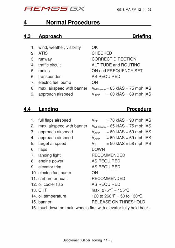
G3-8 MA FM 1211 - 02
4 Normal Procedures
Supplement Glider Towing 11 - 8
4.3 Approach Briefing
1. wind, weather, visibility OK
2. ATIS CHECKED
3. runway CORRECT DIRECTION
4. traffic circuit ALTITUDE and ROUTING
5. radios ON and FREQUENCY SET
6. transponder AS REQUIRED
7. electric fuel pump ON
8. max. airspeed with banner VNE banner = 65 kIAS = 75 mph IAS
9. approach airspeed VAPP = 60 kIAS = 69 mph IAS
4.4 Landing Procedure
1. full flaps airspeed VFE = 78 kIAS = 90 mph IAS
2. max. airspeed with banner VNE banner = 65 kIAS = 75 mph IAS
3. approach airspeed VAPP = 60 kIAS = 69 mph IAS
4. approach airspeed VAPP = 60 kIAS = 69 mph IAS
5. target airspeed VT = 50 kIAS = 58 mph IAS
6. flaps DOWN
7. landing light RECOMMENDED
8. engine power AS REQUIRED
9. elevator trim AS REQUIRED
10. electric fuel pump ON
11. carburetor heat RECOMMENDED
12. oil cooler flap AS REQUIRED
13. CHT max. 275°F = 135°C
14. oil temperature 120 to 266°F = 50 to 130°C
15. banner RELEASE ON THRESHOLD
16. touchdown on main wheels first with elevator fully held back.
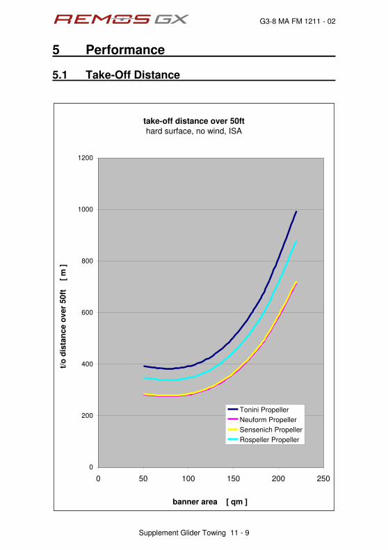
G3-8 MA FM 1211 - 02
5 Performance
Supplement Glider Towing 11 - 9
5.1 Take-Off Distance
take-off distance over 50ft
hard surface, no wind, ISA
0
200
400
600
800
1000
1200
0 50 100 150 200 250
banner area [ qm ]
t/o
dis
tan
ce
over
50
ft [
m ]
Tonini Propeller
Neuform Propeller
Sensenich Propeller
Rospeller Propeller

G3-8 MA FM 1211 - 02
5 Performance
Supplement Glider Towing 11 - 10
5.2 Effects on Take-Off Distance Take-off distances given apply for ISA conditions and a dry, hard runway surface. Various circumstances have an effect on take-off and landing performance. According to ICAO-circular 601AN/55/2, it is recommended to use following add-ons for roll and air distances:
add-ons on take-off roll distance
for dry grass + 20%
for wet grass + 30%
for soft surface + 50%
per 2 knots tailwind component + 10%
per 10 knots headwind component - 10%
for high temperatures above standard + 10% per 10°C
for altitude above sea level (density altitude) + 5% per 1,000 ft
add-ons on take-off air distance
for dirty wings/raindrops + 15%
per 2 knots tailwind component + 10%
per 10 knots headwind component - 10%
for high temperatures above standard + 10% per 10°C
for altitude above sea level (density altitude) + 5% per 1,000 ft
All flight performance data are given for ISA standard atmosphere at sea level and standard temperature. To determine temperature in relation to ISA conditions please refer to the following chart.
NOTE
Especially in banner towing the take-off distances can vary significantly with precise flying habits and the drag of the banner.

G3-8 MA FM 1211 - 02
5 Performance
Supplement Glider Towing 11 - 11
ISA std. Temperature
0
1000
2000
3000
4000
5000
6000
7000
8000
9000
10000
11000
12000
13000
14000
15000
-15 -10 -5 0 5 10 15
temperature [ °C ]
pre
ssu
re a
ltit
ud
e
[
ft ]
G3-8 MA FM 1211 - 02
6 Weight and Balance
Supplement Glider Towing 11 - 12
6.1 General When the aircraft is used for banner towing, the weight and balance calculations for the standard configuration are valid also for towing operations. Concerning payload, there are some restrictions which have to be observed, see also Section 3 within this supplement.
6.2 Required Equipment The following additional equipment is required to use aircraft the for glider towing, and must be taken into account in the weight and balance:
‚ TOST tow release clutch, type E 85
‚ REMOS mounting frame for tow release clutch
‚ release handle (colour yellow)
‚ REMOS oil temperature regulation flap
‚ rear view mirror The following equipment is not part of the center of gravity calculation, but is also necessary for glider towing:
‚ towing rope with ring connector
‚ weak link 300 daN (green)
NOTE
The pilot has to ensure that the required weak link is attached to the tow rope; otherwise the structure of the aircraft may become overloaded!

G3-8 MA FM 1211 - 02
7 Systems
Supplement Glider Towing 11 - 13
The tow release handle is installed inside the cabin of the REMOS GX. The handle is located on the left hand side of the pilot seat, colored yellow. Pulling the handle releases the tow rope. The handle should provide a free play of 1/2 to 1 Inch.

G3-8 MA FM 1211 - 02
8 Aircraft Ground Handling and Service
Supplement Glider Towing 11 - 14
During regular servicing intervals, the tow release clutch must be cleaned, lubricated and checked to assure proper operation. A general overhaul of the release clutch must be conducted every 4 years or 4,000 towing operations, whatever comes first. For further kphqtocvkqp" tghgt" vq" vjg" ugrctcvg" qrgtcvqtÓu" ocpwcn" qh" vjg"manufacturer.

G3-8 MA FM 1211 - 02
Imprint
Pilot Operating Handbook REMOS GX Supplement Banner Towing
ASTM Edition
Copyright REMOS AG © REMOS 2007-2015, all rights reserved

POH Supplement Î Continued Airworthiness

G3-8 MA FM 1212 - R02
Supplement Glider Towing
Supplement Continued Airworthiness 12 - 1
Table of Content
sect. description page
1 Purpose 11-2
2 Continued Airworthiness System 11-3
3 Owner/Operator Responsibilities 10-5
4 Release of Notices to the Public 10-7
5 Documentation Update 10-8
6 Maintenance and Annual Condition Inspection 10-9
7 Modifications or Change of Equipment 10-10
8 Repairs 10-12
9 Contact Data 10-13
G3-8 MA FM 1212 - R02
1 Purpose
Supplement Continued Airworthiness 12 - 2
Continued Airworthiness is everything that is required to keep an aircraft in a safe condition to fly. This does not only include the technical part like maintenance and annual condition inspection. It also includes update of documentation, e.g. Pilot Operating Handbook, issuing repair instructions and repair approvals, change on equipment and feedback of the customer to the manufacturer. Especially the latter one is really important as this is the only way that the manufacturer gets to know of potential issues of safety of flight. In some areas the procedures of the continued airworthiness system of an LSA differ significantly from the ones of a standard category aircraft. This POH supplement shall give guidance to the customer how to act correctly in the continued airworthiness system and how to keep his aircraft airworthy and legal to fly.
G3-8 MA FM 1212 - R02
2 Continued Airworthiness System
Supplement Continued Airworthiness 12 - 3
REMOS AG shall be informed about potential issues of safety of flight or service difficulties by means of the Customer Feedback Form G3-8 MA CA 0050. This document is attached to the maintenance manual and is also available on the website www.remos.com. If a customer does not inform the manufacturer by means of this form, REMOS AG also accepts any way of information as long as it contains at least following information:
‚ aircraft make and model
‚ serial number and callsign
‚ propeller make and model
‚ total time of aircraft and engine
‚ use of aircraft: private or commercial
‚ name and contact data of reporting person
‚ description of potential issue of safety or service difficulty
Once the customer has notified REMOS AG, the information will be forwarded immediately to the Head of Design by means of the customer feedback form. Shall the customer opt for e-mail notification via [email protected] then this e-mail will immediately forwarded to the Head of Design. Based on the information given in the customer feedback form, the Head of Design will perform a risk assessment. In most cases, the Head of Design will contact the customer to collect more and precise information. This includes eventual cooperation with authorities, e.g. in case of an accident.

G3-8 MA FM 1212 - R02
2 Continued Airworthiness System
Supplement Continued Airworthiness 12 - 4
A risk assessment consists of:
‚ cause of accident/incident by pilot error or technical background
‚ safety effect determination
‚ risk assessment evaluation
‚ decision of required alerting of the public
‚ decision of corrective action
The continued airworthiness system of REMOS AG does not only cover events that have occurred during operation of the aircraft. Proposals for improvements or corrections, service difficulties, findings during maintenance events or annual condition inspections are also covered by the continued airworthiness system. In case that service staff identifies a potential safety of flight issue or a real service/maintenance problem, a customer feedback form must be filled out and handed forward to the Head of Design. The customer shall not be afraid of consequences like revoking licenses. This is not the intention and not the job of an aircraft manufacturer. If there is no immediate danger for other customers or the flying public, REMOS AG will never notify authorities.
G3-8 MA FM 1212 - R02
3 Owner/Operator Responsibilities
Supplement Continued Airworthiness 12 - 5
During handover of the aircraft the owner/operator is introduced into the continued airworthiness system of REMOS AG. The customer is informed about the following:
‚ The maintenance handbook provides all information that the customer needs to comply with the regulations, especially with continued airworthiness and maintenance.
‚ Kv" ku" vjg" qypgt1qrgtcvqtÓu" tgurqpukdknkv{" vq" rtqxkfg" vjg"manufacturer with current contact information. Only with current contact information the manufacturer is able to contact the customer in case service bulletins or safety alerts need to be sent out.
‚ In case a safety of flight issue or significant service difficulty reveals, it is the responsibility of the owner/operator to inform the manufacturer. The owner/operator shall not seek for solutions on his own and modify the aircraft I a way that is not covered by the maintenance manual.
‚ Shall the manufacturer release a notice of corrective action it is the responsibility of the owner/operator to comply with it. Furthermore the owner/operator has the responsibility to comply with all applicable aviation authority regulations in regard to maintaining the airworthiness of the LSA airplane.
‚ In case the manufacturer has released a notice of corrective action the owner complete it within the timeframe defined in the notice. If there is no timeframe defined, than the latest time to comply with it is the next annual condition inspection.
‚ In case the owner/operator does not comply with the maintenance manual and/or releases of corrective action, the LSA is not in compliance with the accepted ASTM consensus standards. This means that the aircraft is not airworthy and operating this aircraft is not legal. In case the responsible aviation authority (in case of the USA this is FAA) gets to know about this the owner/operator may be subject to regulatory action by the authority.
G3-8 MA FM 1212 - R02
3 Owner/Operator Responsibilities
Supplement Continued Airworthiness 12 - 6
This information is provided by means of the customer commitment form, which is part of the maintenance manual. The owner/operator shall sign this form and send it to REMOS AG. On this form the owner/operator shall also provide the manufacturer with current contact data. If the aircraft is sold to another customer a new customer commitment form needs to be signed. This form will have the identical document number added by a dash and a counting number starting with 1 to make clear that this new form is a new revision.
G3-8 MA FM 1212 - R02
4 Releases of Notices to the Public
Supplement Continued Airworthiness 12 - 7
There are three different levels of notices to the public, each representing a different level of importance:
‚ SAFETY ALERT will be issued in case of an urgent safety of flight situations. Potentially an emergency safety of flight action is required in this case. Owner/operators will immediately be informed by postal mail and an immediate action is required. In addition, all safety alerts will be published on the website www.remos.com
‚ SERVICE BULLETIN will be issued in case a corrective action, a mandatory inspection or a modification of the aircraft is required. Owner/operators must be informed by postal mail. An immediate action is not required but a future action is required or recommended. In addition, all safety alerts will be published on the website www.remos.com
‚ NOTIFICATION will be issued in case service information is required, but owner/operators will not be informed by postal mail. The public is notified via the website www.remos.com only.

G3-8 MA FM 1212 - R02
5 Documentation Update
Supplement Continued Airworthiness 12 - 8
Any documentation update will be released on the website www.remos.com Owner/operators will not be informed by postal mail, unless such a documentation update is mandatory for safety of flight and is released by a safety alert or a service bulletin. Examples for documentation updates are new revisions of:
‚ Pilot Operating Handbook
‚ Service and Maintenance Checklist
‚ Annual Condition Inspection Checklist
‚ Type Design Datasheet
For copyright reasons a new revision of the maintenance handbook is not available on the website, but only on request as hardcopy.

G3-8 MA FM 1212 - R02
6 Maintenance and Annual Cond. Inspection
Supplement Continued Airworthiness 12 - 9
Maintenance intervals of all REMOS aircraft are 25h for the first maintenance event, followed by 100h inspections. In case that AVGAS 100LL is used for more than 30% of the time, oil change interval is reduced to 50h. REMOS AG hereby defines the following persons that may perform maintenance and repair as defined in the Maintenance Manual including 25h and 100h inspection:
‚ Owner/operator: with Sport Pilot Certificate or higher: preventative maintenance, or line maintenance.
‚ LSA Repairman Maintenance: preventative maintenance, line maintenance, or heavy maintenance.
‚ A&P Mechanic: preventative, maintenance, line maintenance, or heavy maintenance.
‚ Part 145 Repair Station with appropriate ratings: preventative maintenance, line maintenance, or heavy maintenance
REMOS AG hereby defines the following persons that may perform the annual condition inspection:
‚ LSA Repairman Maintenance
‚ A&P Mechanic
‚ Part 145 Repair Station with appropriate ratings
Always use REMOS documents for your maintenance events and the annual condition inspection. These documents are available on the website www.remos.com

G3-8 MA FM 1212 - R02
7 Modifications or Change of Equipment
Supplement Continued Airworthiness 12 - 10
Certified equipment is listed in the maintenance manual. Only listed equipment may be installed on the aircraft without notifying REMOS AG. In case equipment that is described in the maintenance manual shall be exchanged on the aircraft, it is required to:
‚ update equipment list
‚ weight and balance
Modifying the aircraft or changing equipment may be performed by any competent person. Updating the equipment list and the weight and balance report may only be performed by
‚ LSA Repairman Maintenance
‚ A&P Mechanic
‚ Part 145 Repair Station with appropriate ratings
Any change that is not documented may not be performed on the aircraft without having it certified by REMOS AG. Nevertheless, it is possible to do so. Notify REMOS AG prior to the intended change of the aircraft. Engineering department will then decide which kind of documentation is required and will either prepare them or will ask the customer to have this documentation prepared. Followed by this a Letter of Approval (LOA) will be prepared that needs to be signed by either an A&P Mechanic or a Part 145 Repair Station with appropriate ratings after the work is accomplished. Then this LOA will be signed by the Head of Design of REMOS AG and handed out to the customer. This procedure will be performed by e-mail. The extent of work cannot generally be defined; it is always an individual project. Working hours of the engineering department will be charged by the hour according to actual pricelists. This procedure is not intended and built up for the manufacturer to make money of it. In contrary, due to running projects within engineering department it usually costs more to prepare the documentation than it is charged for. This procedure is defined in the regulations, in this case ASTM F2483.

G3-8 MA FM 1212 - R02
7 Modifications or Change of Equipment
Supplement Continued Airworthiness 12 - 11
Without having updated the equipment list and weight and balance or not having changes approved by the manufacturer that are not part of the maintenance manual, the aircraft is considered not airworthy and unsafe to fly. It is not legal to operate an aircraft without a current equipment list and weight and balance and required approvals by the manufacturer. Make sure the change of equipment ku"ukipgf"qhh" kp" vjg"cktetchvÓu" nqidqqm"cpf" ku"gpvgtgf" kp" vjg"cktetchvÓu"permanent record.

G3-8 MA FM 1212 - R02
8 Repairs
Supplement Continued Airworthiness 12 - 12
Repairs are handled similarly as change of equipment. Any repair that is performed with standard tools by replacing damaged parts may be performed by any competent person. To release the aircraft back to service the repair must be signed off by
‚ Owner/Operator with at least a Sport Pilot Licence
‚ LSA Repairman Maintenance
‚ A&P Mechanic
‚ Part 145 Repair Station with appropriate ratings
It is recommended to perform a standard maintenance event and an annual condition inspection once a repair has been performed that could affect safety of flight. Structural repairs that are described in the maintenance manual are handled identically. In case the damage exceeds the described ones, an individual repair instruction is required. In this case notify REMOS AG by means of the customer feedback form. Engineering will then prepare individual and precise repair instructions. Repairing a composite aircraft is completely different from repairing a metal aircraft or a composite boat. Therefore only competent persons may perform the work. REMOS AG hereby defines the following persons that may perform the repair:
‚ LSA Repairman Maintenance with composite knowledge
‚ A&P Mechanic with composite knowledge
‚ Part 145 Repair Station with appropriate ratings
Notify REMOS AG prior to the intended repair. Engineering department will then decide which kind of repair and documentation is required and will either prepare them or will ask the customer to have this documentation prepared. Followed by this a Repair Approval (LOA) will be prepared that needs to be signed by either an A&P Mechanic or a Part 145 Repair Station with appropriate ratings after the work is accomplished. Then this Repair Approval will be signed by the Head of Design of REMOS AG and handed out to the customer. This procedure will be performed by e-mail.

G3-8 MA FM 1212 - R02
8 Repairs
Supplement Continued Airworthiness 12 - 13
The extent of work cannot generally be defined; it is always an individual project. Working hours of the engineering department will be charged by the hour according to actual pricelists. This procedure is not intended and built up for the manufacturer to make money of it. In contrary, due to running projects within engineering department it usually costs more to prepare the documentation than it is charged for. This procedure is defined in the regulations, in this case ASTM F2483. Without having the repair performed and approved according to the ocpwhcevwtgtÓu"kpuvtwevkqp"vjg"cktetchv"ku"eqpukfgtgf"pqv"cktyqtvj{"cpf"unsafe to fly. It is not legal to operate an aircraft without current documentation and required approvals by the manufacturer. Make uwtg"vjg"tgrckt"ku"ukipgf"qhh"kp"vjg"cktetchvÓu"nqidqqm"cpf"ku"gpvgtgf"kp"vjg"cktetchvÓu"rgtocpgpv"tgeqtf0

G3-8 MA FM 1212 - R02
9 Contact Data
Supplement Continued Airworthiness 12 - 14
The manufacturer of the REMOS aircraft and the only responsible entity for continued airworthiness is
REMOS AG
Franzfelde 31 D-17309 Pasewalk
G E R M A N Y
Tel: +49-3973-225519-0 Fax: +49-3973-225519-99
Email: [email protected] Web: www.remos.com
G3-8 MA FM 1212 - R02
Imprint
Pilot Operating Handbook REMOS GX Supplement Glider Towing
ASTM Edition
Copyright REMOS AG © REMOS 2007-2015, all rights reserved