Embed Size (px)
Citation preview
Computers and Geotechnics 9 (1 990) 291-305
PILES UNDER AXIAL AND TORSIONAL LOADS
Michael Georgiadis and Sofia Saflekou Department of Civil Engineering
Aristotle University of Thessaloniki Greece
ABSTRACT
An analysis of axially and torsionally loaded piles is presented in which the pile is treated as an elastic bar supported on two series of interacting non-linear axial and torsional springs. The characteristics of these springs depend on the soil properties and the diameter of the pile as well as on the interaction between the axial and torsional response. Predicted pile responses ape compared to the results of model tests conducted on piles installed in soft clay bed and loaded with combined axial and torsional loads. Both experi- mental results and theoretical predictions show that a torque applied to the pile head affects significantly the settlement and the axial bearing capacity of the pile.
INTRODUCTION
Pile foundations are normally designed ~o support axial and la<eral loa4s
which result from the weight of the structure and any acting sea wave or seismic
forces. The analysis of pile response for these types of loading can be per-
formed with several methods which ar~ either considering the soil as an elastic
/ elasto-plastic half-space [I-3] or, more often in practice, as a series of non
linear springs [4-9].
Although axial and lateral are the main forms of loading, the foundation
piles of some types of structures, especially offshore structures, are liable to
receive significant torsional loads which are caused by the eccentricity of the
applied lateral forces. Methods for analyzing the pile response under torsional
loading have been presented in references [10], [11] and [12]. All methods of
analysis consider that axial, lateral and torsional loads act independently,
assuming that there is no interaction. The influence of torque on axial pile
response and the influence of axial load on torsional pile response were dis-
cussed by Georgiadis [13]. It was shown, using a simple elastoplastic spring
291
Computers and GeotechnicsO266-352X/90/$03.50 © 1990 Elsevier Science Publishers Ltd, England. Printed in Great Britain
292
model, that the interaction between axial and torsional pile responses contri-
butes significantly to the global pile response, resulting in large~ ~ axial
displacements and rotatiens.
This paper presents the results of an experimental investigation in which
model piles in clay were subjected to combined axial and torsional loads to
study the effect of torsion on axial pile response. The experimental results
were compared to the results of a numerical analysis in which the soil was ~rea-
ted as two series of interacting non-linear springs (~xial and torsional). Fi-
nally, the numerical analysis was applied to the case of a typical full size
offshore pile.
NUMERICAL ANALYSIS
The analysis was conducted with the numerical model presented in reference
[13] but with some essential changes which were made in order to account for
the non-linearity of the soil and to improve the interaction between axial and
torsional springs. The pile is considered as an elastic bar of length L, which
is divided by "n" nodes into (n-l) segments of length i= L/(n-1). The soil is
treated as two series of non-linear springs (one axial and one torsional) which
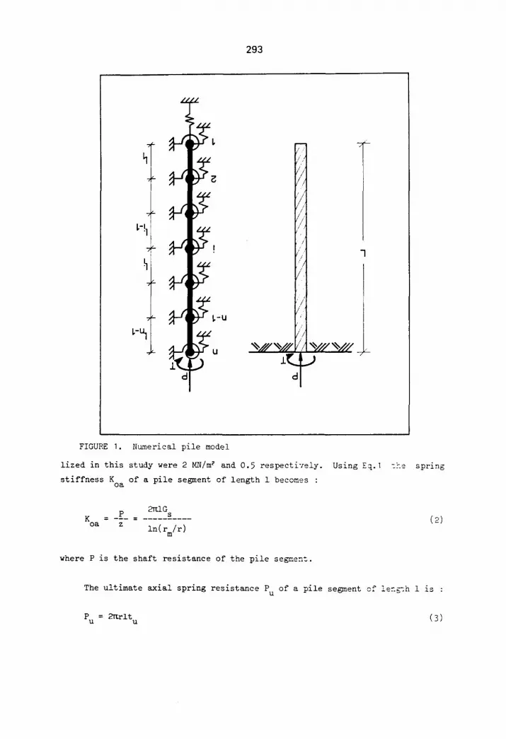
are attached to the pile nodes (Figure I). Another spring is connected to the
pile base to represent the end bearing resistance. A torsional base spring is
not introduced in the analysis because its contribution to the response of or-
dinary piles is expected to be minor 110].
(i) Spring Characteristics
The first step in the analysis is to establish the load-displacement rela-
tionships of the axial springs and the torque-rotation relationships of the
torsional springs. The load-displacement relationship of an axial spring is
characterized by an initial stiffness K a non-linear part and an ultimate load oa
P at which the spring fails (Figure 2a). The initial stiffness K was deter- u oa
mined using an analytical formula proposed by Randolph and Wroth [3] for axially
loaded rigid piles in an elastic half-space :
z = (tr/Gs)in(rm/r) (I)
where z is the axial displacement, t the pile shaft load per unit area, G s the
shear modulus of the soil, r the pile radius, r the radius of the zone of in- m
fluence beyond which the shear stress becomes negligible rm= 2.5L(I"Ms) and M s
the Poisson's ratio of the soil. The values of G and ~ of the clay bed uti- s s
293
s
L-!I~ f
hll ~-U
U
d
T
7L-
FIGURE I. Numerical pile model
lized in this study were 2 MN/m ~ and 0.5 respectively.
stiffness K of a pile segment of length 1 becomes : oa
2~lG P s
K = --- = .......... oa z ln(rm/r)
where P is the shaft resistance of the pile segment.
Using Eq. 1 t h e spring
(2)
The ultimate axial spring resistance P U
P = 2~rlt U U
of a pile segment of !en~h 1 is :
(3)
294
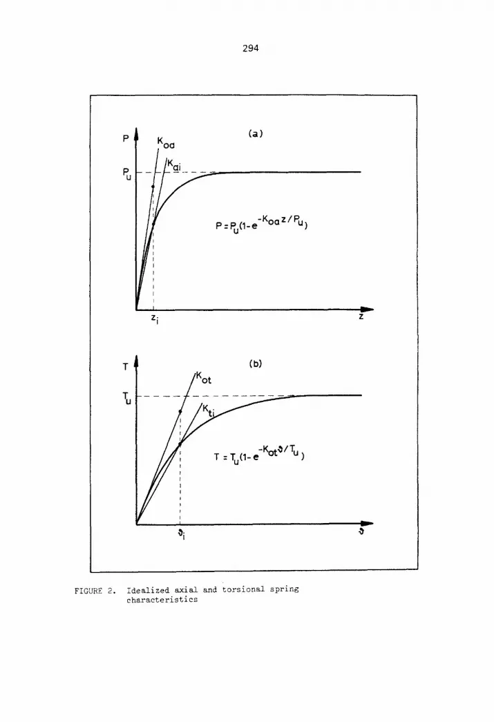
p ~ Koa (a)
P = Pu(1- e -Koa
z i
z/Pu)
z
(b) T /o: . . . .
. . . . . T = Tu(I-e u~-///' -KotO/Tu >
v
FIGURE 2. Idealized axial and torsional spring characteristics
295
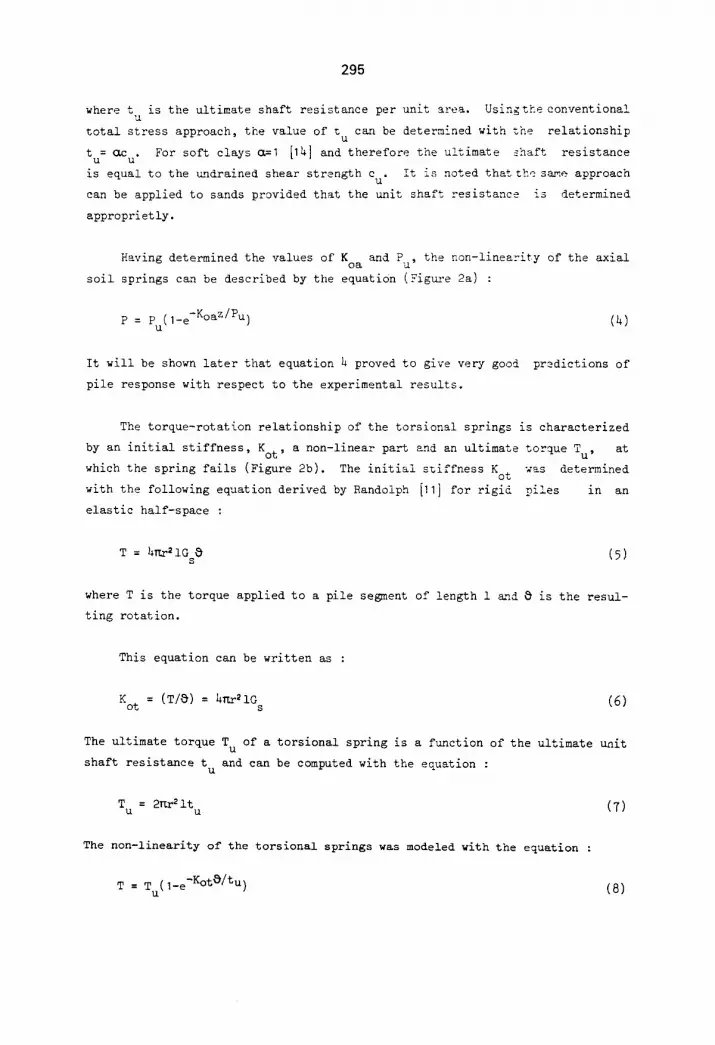
where t is the ultimate shaft resistance per unit area. Usingtheconventional u total stress approach, the value of t can be determined with she relationship u
t = cuz . For soft clays a=1 [141 and therefore the ultimate shaft resistance u u
is equal to the undrained shear strength c . It is noted that the same approach u
can be applied to sands provided that the unit shaft resistance is determined
approprietly.
Having determined the values of K oa
soil springs can be described by the equation (Figua-e 2a) :
p = Pu(l-e-Koaz/Pu )
It will he shown later that equation 4 proved to give very good
pile response with respect to the experimental results.
and Pu' the non-linearity of the axial
(4)
predictions of
The torque-rotation relationship of the torsional springs is characterized
by an initial stiffness, Kot, a non-linear part and an ultimate torque Tu, at
which the spring fails (Figure 2b). The initial s%iffness Kot was determined
with the following equation derived by Randolph [11] for rigid piles in an
elastic half-space :
T = 4r~r21G ~ (5) s
where T is the torque applied to a pile segment of length 1 s2~d ~ is the resul-
ting rotation.
This equation can be written as :
Kot : (T/S) : 4rLr21O s (6)
The ultimate torque T u of a torsional spring is a function of the ultimate unit
shaft resistance t u and can be computed with the equation :
T u = 2Kr21t u (7)
The non-linearity of the torsional springs was modeled with the equation :
T = Tu(1-e-K°t~/tu ) (8)
296
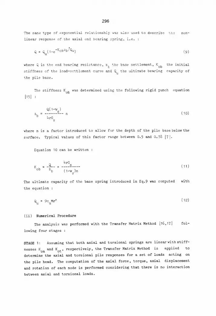
The same type of exponential relationship was also used to describe
linear response of the axial end bearing spring, i.e. :
Q : Qu(1-e-KobZb~Qu )
where Q is the end bearing resistance, z the base settlement, Kob c
stiffness of the load-settlement curve and Qu the ultimate bearing
the pile base.
t he non-
(9)
the initial
capacity of
The stiffness Kob was determined using the following rigid punch equation
[15]:
q(1-v ) s
Z. ---- ......... n 0 4rO
s
(10)
where n is a factor introduced to allow for the depth of the pile base below the
surface. Typical values of this factor range between 0.5 and 0.78 [7].
Equation 10 can be written :
4rG __Q ....... s ....
K°b : Zb ( 1-V )n s
(11)
The ultimate capacity of the base spring introduced in Eq.9 was computed with
the equation :
Qu = 9Curer2 (12)
(ii) Numerical Procedure
The analysis was performed with the Transfer Matrix Method [16,17]
lowing four stages :
fol-
STAGE I: Assuming that both axial and torsional springs are linear with stiff-
nesses K and K respectively, the Transfer Matrix Method is applied to oa ot '
determine the axial and torsional pile responses for a set of loads acting on
the pile head. The computation of the axial force, torque, axial displacement
and rotation of each node is performed considering that there is no interaction
between axial and torsional loads.
297
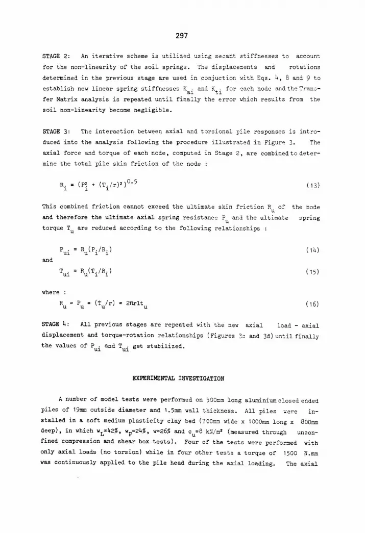
STAGE 2: An iterative scheme is utilized using secant stiffnesses to account
for the non-linearity of the soil springs. The displacements and rotations
determined in the previous stage are used in conjuction with Eqs. 4, 8 and 9 to
establish new linear spring stiffnesses Kai and Kti for each node and the Trans-
fer Matrix analysis is repeated until finally the error which results from the
soil non-linearity become negligible.
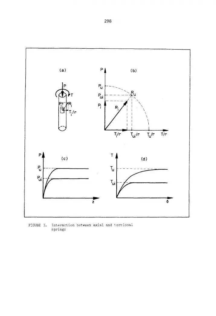
STAGE 3: The interaction between axial and torsional pile responses is intro-
duced into the analysis following the procedure illustrated in Figure 3. The
axial force and torque of each node, computed in Stage 2, are combined to deter-
mine the total pile skin friction of the node :
R i = (P~ + (Ti/r)2)0"5 (13)
This combined friction cannot exceed the ultimate skin friction R of u and therefore the ultimate axial spring resistance P and the ultimate
U
torque T u are reduced according to the following relationships :
the node
spring
and
Pui = Ru(Pi/Ri)
Tui = Ru(Ti/R i)
I~)
15)
where :
R U
= (T /r) = 2T~rlt = Pu u u 16)
STAGE 4: All previous stages are repeated with the new axial load - axial
displacement and torque-rotation relationships (Figures 3c and 3d) until finally
the values of P . and T . get stabilized. Ul Ul
EXPERIMENTAL INVESTIGATION
A number of model tests were performed on 500mm long aluminiumc!osed ended
piles of 19mm outside diameter and 1.5mm wall thickness. All piles were in-
stalled in a soft medium plasticity clay bed (700r~m wide x 1000mm long x 800mm
deep), in which WL=42% , Wp=24%, w=26% and Cu=8 kN/m 2 (measured throu~q uncon-
fined compression and shear box tests). Four of the tests were performed with
only axial loads (no torsion) while in four other tests a torque of 1500 N.~m
was continuously applied to the pile head during the axial loading. The axial
298
(a)
i
• ,L3-FTi/r
:3
P
Pu
Pui
(b)
"-#~ I \ 1 \ I \ b \
'
I \
'~lr Tui/r Tu/r T/r"
P (c)
~U . . . .
v
z
L
Li
(d)
y
FIGURE 3. Interaction between axial and torsional springs
299
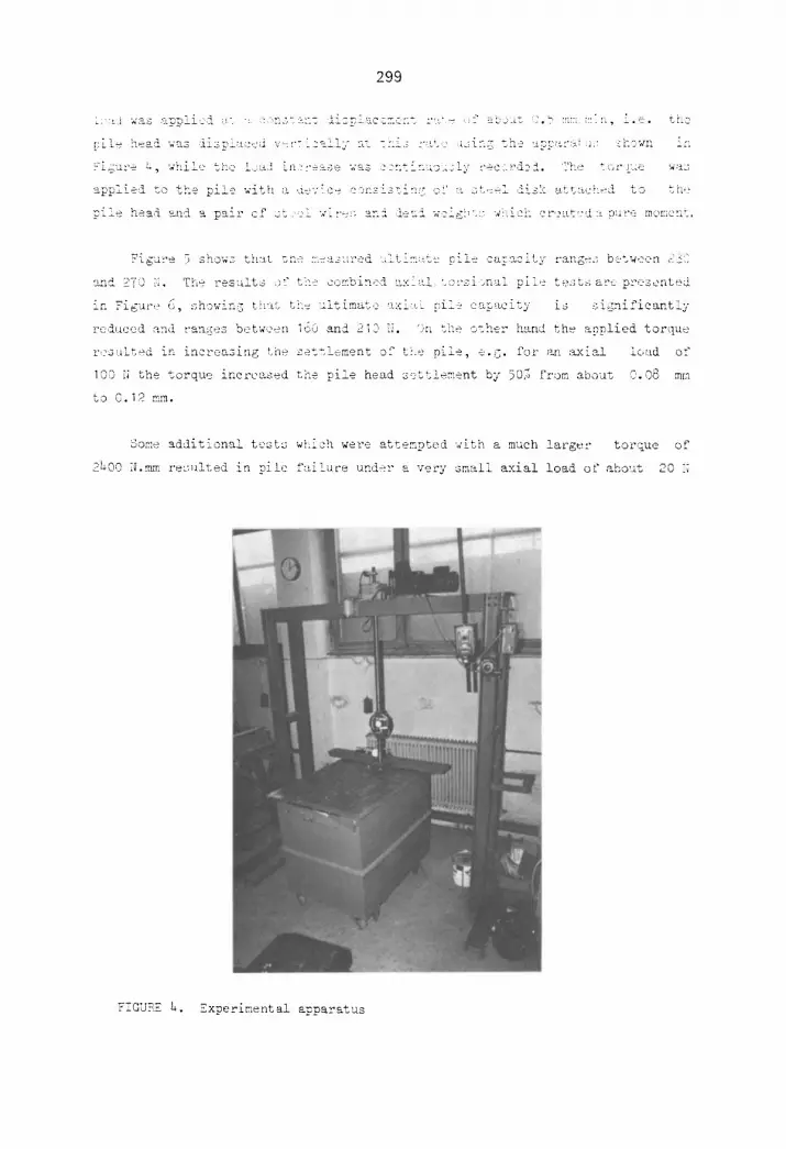
i : : ~ w a s a p p ! i c d ;~'. ' : n , - ~ ' ~ - l i s p l < e _ m e : : t ='~:," - f -~t__~--. ~ . b mm :::[:~, i . e . < h e
[ : - i e h e a i wus i i s p i u ~ ' e d v = : ' - i z ~ _ ± i Z RI - _ h i ; ; " , , r e zs i : - .C %he t~[Lp<~:';~ i ~ _ 'hEwn i f !
?'£gur: 4, while thr bad hl?:'e:=se was s~ntirluoazly :'ec,"iDi. 'the to:-'.ue w;~s
applied to the pile with a dev'c~' , c0r:sis<in!; o f "< st:~i iisk u, tb:~.c!i~d to th{~
p i l e h e a d a n d a pal_," c f s t , i w-~-<; a n ! i ~ u l w c i g b u : - w % i c k c r , ~ t ~ ' d : ~ , p u r e memo: i t ,
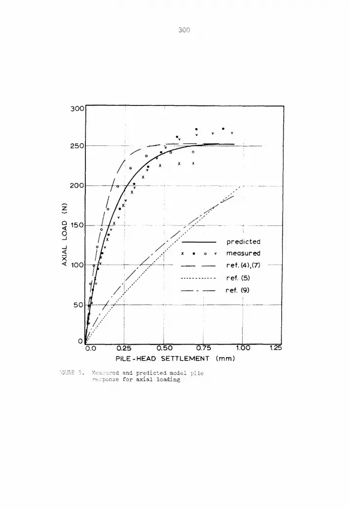
Figure 5 shows th:~t ~.e measured u!tim;~t~ p-!e cay~mity ~'anges b:.tween ~-3:~
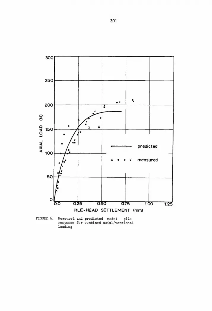
and 27] N. The results :~'f the -~,y~.bin<i '.v<ial to'--siena! pile testsar< presented
in Figure ,., <, showin S tiv:,~ tke '~_~;~',~,-~..~_.= %zi~.L pile cap,~city is significantly
,_~=~ce,a and ran6es between i00 and ~I_ ~ N ':atke other h'~nd th~ ~pplied torque
res ~lted in increasing the settlement of tie pile, e. 6. for ~ :~<ial load of
]00 N the torque incre~sed the pile head sett!e~:ent hy 50]~ from about 0.0~ m~.<
to 0.12 ram.
Some additional tests which were attempted with a much larger torque of
~,_0 N.mm resulted in pile f<~i!u~-e u~d~,r a very small axial load o~ about 20 N
FIGURE L. Experimental apparatus
300
3 0 0
2 5 0
2 0 0
v
r,, 1 5 0 < 0 /
_ J <
< 100
5 0
, , , ' "
t ,"
0 '" 0.0
v V v I V
/ ° / ; .. ! • X
I h .>" o/:~ ..../
? ..................................... 2::;- ? .... : ..... x , . . n r e d i c f e d .'°
x • o v m e a s u r e d
- - - - ~ W ~ re f . (4),(7)
i A ,"" j ,
. . . . . . . . . . . . r e f . ( 5 )
ref . (9)
0 . 2 5 0 . 5 0 0:175
P I L E - H E A D S E T T L E M E N T ( m m )
1,00 1.25
:GUBE 5. Z e u . ; ; r e d and predicted model pile re ponse for axial loading
301
300
250
200
A
z
a ,,~ 150
9 .J <
< 1 0 0
50
o
0 VII
FIGURE 6.
¢
0 0.0
0
X X
• ¥
X • 0 V
predicted
meosured
0.25 O.:iO 0.~5
PILE-HEAD SETTLEMENT (mm)
Measured and predicted model pile response for combined axial/torsional loading
1.~ )0 1.2 j=
302
which is equivalent to the end bearing capacity of the pile.
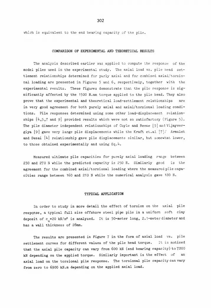
COMPARISON OF EXPERIMENTAL AND THEORETICAL RESULTS
The analysis described earlier was applied to compute the response of the
model piles used in the experimental study. The axial load vs. pile head set-
tlement relationships determined for purly axial and for combined axial/torsio-
nal loading are presented in Figures 5 and 6, respectively, together with the
experimental results. These figures demonstrate that the pile response is sig-
nificantly affected by the 1500 N.mm torque applied to the pile head. They also
prove that the experimental and theoretical load-settlement relationships are
in very good agreement for both purely axial and axial/torsional loading condi-
tions. Pile responses determined using some other load-displacement relation-
ships [4,5,7 and 9] provided results which were not so satisfactory (Figure 5).
The pile diameter independent relationships of Coyle and Reese [5] and Vijayver-
giya [9] gave very large pile displacements while the Kraft et.al [7]/ Armaleh
and Desai [41 relationship gave pile displacements similar, but somewhat lower,
to those obtained experimentally and using Eq.4.
Measured ultimate pile capacities for purely axial loading r<nge between
230 and 270 N while the predicted capacity is 250 N. Similarly good is the
agreement for the combined axial/torsional loading where the measured pile capa-
cities range between 160 and 210 N while the numerical analysis gave 180 N.
TYPICAL APPLICATION
In order to study in more detail the effect of torsion on the axial pile
response, a typical full size offshore steel pipe pile in a uniform soft clay
deposit of c =20 kN/m 2 is analyzed. It is 50-meter long, 2.]-meterdiameterand u
has a wall thickness of 28mm.
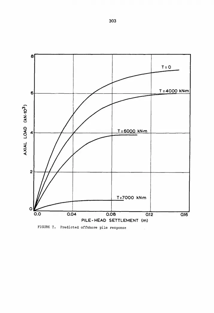
The results are presented in Figure 7 in the form of axial load vs. pile
settlement curves for different values of the pile head torque. It is noticed
that the axial pile capacity can vary from 600 kN (end bearing capacity)to 7200
kN depending on the applied torque. Similarly important is the effect of an
axial load on the torsional pile response. The torsional pile capacity can vary
from zero to 6900 k2{.m depending on the applied axial load.
303
8
T=O
6 I - T : 4000 kN.m
Q
i 0.0 0.04 0.0B 0.12 0.16
PILE-HEAD SETTLEMENT (m)
Predicted offshore pile response FIGURE 7.
304
CONCLUSIONS
The experimental work presented in this paper has proved that the interac-
tion between axial and torsional pile responses has an important influence on
global pile behavior.
A torque applied to the pile head results, in addition to the rotation of
the pile, in reducing the ultimate axial bearing capacity and increasing the
settlement. The same conclusion was also derived from a numerical analysis
which considers the soil as two series of interacting non-linear axial and tor-
sional springs.
The simplicity of the analysis, coupled with the good agreement achieved
between the predicted and measured pile responses to combined axial / torsional
loads, suggests that it may prove to be of considerable value. The conventional
approach of separate examination of the axial and torsional pile responses may
in some cases overestimate seriously the pile capacity and underestimate the
pile movements.
I.
2.
3.
5.
6.
7.
REFERENCES
Butterfield, R. and Banerjee, P.K., The elastic analysis of compressible piles and pile groups. Geoteehnique 21 (1971) 43-60.
Poulos, H.G. and Davis, E.H., Pile Foundation Analysis and Design, J.Wiley and Sons, New York (1980).
Randolph, M.F. and Wroth, C.P., Analysis of deformation of vertically loaded piles. J.Geot.En~.Div.A.S.C.E. I04, GT12 (1978) 1465-1488.
Armaleh, S. and Desai, C.S., Load-deformation response of axially loaded piles. J.Geot.En~.A.S.C.E. 113, GT12 (1987) 1483-1500.
Coyle, H.M. and Reese, L.C., Load transfer for axially loaded piles in clay. J.Soil Mecb.Fdns.A.S.C.E. 92, SM2 (1966) 1-26.
Georgiadis, M. and Butterfield, R., Laterally loaded pile behavior. J.Geot.Ens.Div.A.S.C. E. I0__88, GTI (1982) 155-165.
Kraft, L.M., Ray, R.P. and Kagawa, T., Theoretical t-z curves. J.Geot. Eng.Div.A.S.C.E. 107, GT11 (1981) 1543-1561.
305
8. Reese, L.C., Cox, W.R. and Koop, F.D., Field testing and analysis of laterally loaded piles in clay. Proc.Tth Offshore Technolo~D" Conference, Houston Texas, OTC 2312 (1975) 671-690.
9. Vijayvergiya, V.N., Load-movement characteristics of piles. Proc. PORTS'77, Long Beach California (1977) 269-28h.
10. Poulos, H.G., Torsional response of piles. J.Geot.En~.Div.A.S.C.E. 101, GTI0 (1975) 1019-1035.
11. Randolph, M.F., Piles subjected to torsion. J.Geot.En~.Div.A.S.C.E. 107, GT8 (1981) 1095-1111.
12. Chow, Y.K., Torsional response of piles in nonhomogeneous soil. J.Geot.Ens.A.S.C.E. 111, GT7 (1985) 9h2-9h7.
13. Georgiadis, M., Interaction between torsional and axial pile responses. Int.J.Numer.Anal.Methods Geomech. 11, (1987) 645-650.
lb. American Petroleum Institute, Recommended Practice for Planning, Designing and Constructing Fixed Offshore Platforms. API RP 2A (1985).
15. Timoshenko, S.P. and Goodier, J.N., Theory of Elasticity, 3rd ed., McGraw-Hill Book Co.Inc., New York (1970).
16. Georgiadis, M., Flexible Landing Mats on Clay, Ph.D.Thesis, Dept.of Civil Engineering, Univ.of Southampton, U.K. (1979).
17. Pestel, E.C. and Leckie, F.A., Matrix Methods in Elastomechanics, McGraw Hill, London (1963).
Received 20 June 1990; revised version received 12 September 1990; accepted 15 September 1990