Embed Size (px)
Citation preview

04/03/2009
PILE FOUNDATIONS
ByVaranasi Rama Rao
( Engineer- Civil & Structural )

04/03/2009
PrefacePile foundations is a very vast subject and it is not possible to cover all the information regarding pile foundations in one book or presentation. The objective of this presentation is to give an overall view of the subject which will serve as beginners guide. The focus of the presentation is mainly on onshore pile foundations. The author has tried to explain the subject through simple concepts and visuals without giving detailed methodologies or mathematical concepts to maintain the interest of the beginner ,without loading his mind with unnecessary confusion . However, some formulae were presented at some places only to appreciate the statements made. The author assumes that the reader has basic knowledge of soil mechanics and foundation engineering and basic principles of engineering. The author will be pleased to accept comments and suggestions, without deviating from the basic objective of the presentation, for further improvement.
Varanasi Rama Rao

04/03/2009
Contents
3. Pile installationInstallation of Driven pilesInstallation of Bored pilesAdvantages and Disadvantages of various piles
4. MiscellaneousPile driving formulaePile cap configurationsStructural Design of Pile and Pile capFlow chart for Pile selectionReal time pictures of Piles
5. References
1. GeneralOverviewPile capacitiesPile groupsSettlement AnalysisDesign Steps
2. Special TopicsNegative skin frictionSocketed pilesDynamic pile testingPile integrity testingDynamic loading on piles

04/03/2009
1.GENERAL

04/03/2009
Overview
Pile foundations are adopted generally in the following situations:
•Low Bearing Capacity of soil .
•Non availability of proper bearing stratum at shallow depths.
•Heavy loads from the super structure for which shallow foundation may not be economical or feasible.

04/03/2009
Classification of Piles
Based on material • Concrete• Steel• Timber
Based on method of construction/installation.• Driven /Displacement Pre cast Piles• Driven/Displacement Cast in Situ Piles• Bored/ Replacement Pre cast piles• Bored/ Replacement Cast in situ piles.
Based on Load transfer mechanism• End bearing piles • Friction/Floating piles • Bearing cum Friction piles

04/03/2009
Based on sectional area• Circular• Square• H• Octagonal• Tubular
Based on Size• Micro piles dia. < 150 mm • Small dia. pile dia. >150mm and <600 mm• Large dia. piles > 600 mm
Based on inclination• Vertical Piles• Inclined/ raker Piles

04/03/2009
How does a pile look like?
• Before presenting the actual picture of a pile foundation some schematic pictures of pile foundation are presented below.

04/03/2009
Figure 1
All the above schematics show the various types of pile foundations and loads carried by them

04/03/2009
Schematics of Pile foundations based on method of construction
Figure 2

04/03/2009
What are the loads coming on to the pile foundation?
All the loads from super structure viz. Dead loads, Live loads Wind loads and Seismic loads.
The loads from the surrounding soil in case of seismic event.
Water loads in the case of off- shore structures

04/03/2009
Typical loading diagram on a single pile embedded in soil
Soil layer 2
Soil layer 1
Soil layer 3
V
HM
Note: V can be either downward or upward depending on the pile is subjected to compressive or tensile load
Figure 3
04/03/2009
Piles usually exist as groups which are all integrated by means of a pile cap as shown in the below
schematic
Figure 4

04/03/2009
What are the load carrying mechanisms of piles?
• End bearing cum friction piles carry vertical compressive loads partly by means of resistance offered by the hard stratum at the tip of the pile and partly by the friction developed between the pile shaft and soil
• Pure friction piles carry the major part of loads only by means of friction developed between pile shaft and soil; and pure End bearing piles only by means of bearing resistance at the tip of the pile
• In both the above cases lateral loads are carried by the lateral resistance offered by the surrounding soil.

04/03/2009
SCHEMATICS SHOWING AXIAL LOAD CARRYING MECHANISM
Figure 5

04/03/2009 Figure 6
04/03/2009
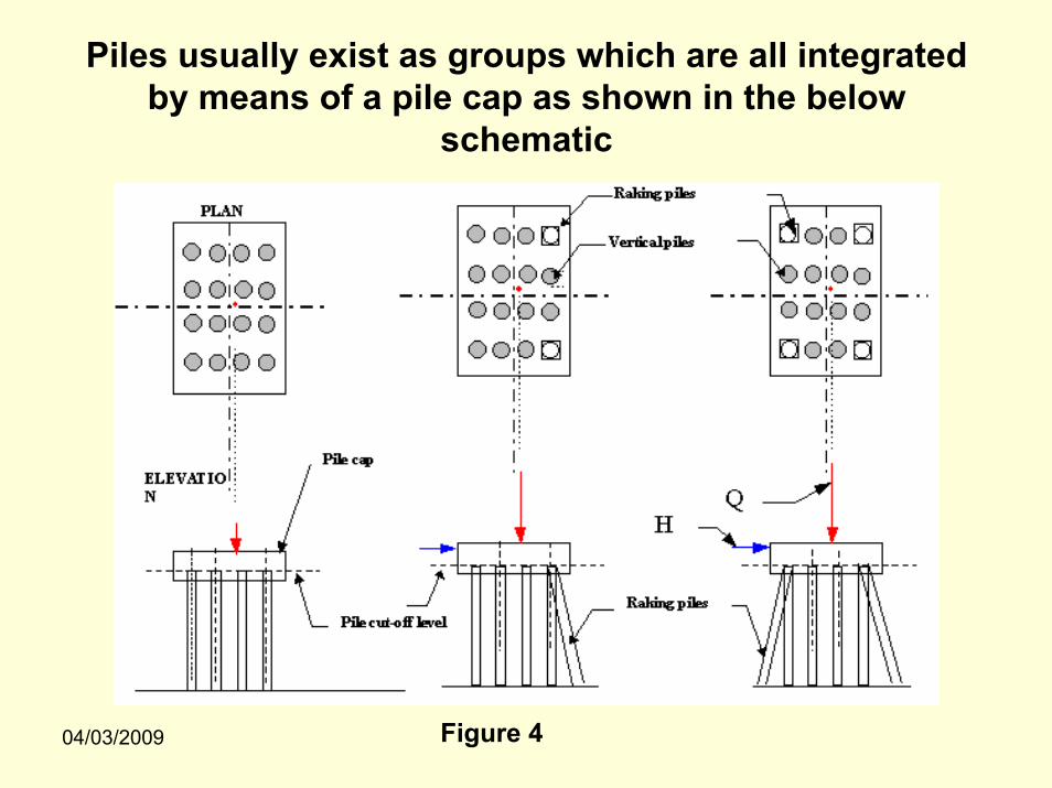
Load carrying mechanism of pile subjected to Lateral Loading and Moment
Y
XFigure 7

04/03/2009
Load carrying mechanism of pile Subjected to tension/pullout
Pile in tensionOnly friction and weight of pile will resist tension.Figure 8

04/03/2009
What is meant by load carrying capacity of the pile foundation?
Load carrying capacity of the pile in the context of foundation engineering:
The amount of load the pile can carry without undergoing continuous displacements for insignificant load increments by virtue of its boundary condition (soil condition) and not by virtue of its structural strength.
the assumption for this definition is – the failure of surrounding soil occurs prior to the failure of the pile material especially in the case of concrete piles
04/03/2009
Pile Capacities
What are the various capacities of pile commonly used in practice?
•Axial capacity
•Lateral capacity
•Pullout capacity or Tension capacity

04/03/2009
How to estimate the capacity of a Pile? What are the approaches?
The two approaches for obtaining capacity of the pile areField approach
In this approach the pile is loaded to the desired level and its capacity is estimated.
Theoretical ApproachIn this approach the pile capacity is calculated using some formulae into which soil data is fed for obtaining the capacity.

04/03/2009
Field Approach
A Test pile of required dimensions is constructed in the field and a load test is conducted to assess the capacity of the pile.
This approach gives more realistic estimate of pile capacity. However it is time consuming and costly

04/03/2009
Load Tests On a Single Pile
The load tests are categorized as
Stress tests
•Maintained load test ( Static vertical load test)
•Constant rate of penetration test
•Lateral load test
•Dynamic load test
•Cyclic load test ( not discussed in this presentation)
Strain tests
•Low strain integrity testing
•High strain integrity testing.

04/03/2009
Pile load tests are usually carried out for the following main reasons:
•To obtain back figured soil data that will enable other piles to be designed
•To confirm pile lengths and hence contract costs before the client is committed to over all job costs
•To counter check results from geotechnical and pile driving formulae
•To determine the load-settlement behavior of the pile, especially in the region of anticipated working load, that the data can be used for prediction of group settlement.
•To verify the structural soundness of the pile.

04/03/2009
Field setup for a Static Axial compressive load test on a single pile
Test Schematic Real time field set up
Figure 9

04/03/2009
Determination of pile axial compressive capacity from static load test
The Pile load test data is presented as shown below
From the above plots the ultimate pile load is commonly taken as the load where the load settlement curve approaches a vertical asymptote
Contd. Next slide
Figure 10

04/03/2009
Lateral Load testJust like axial capacity, lateral capacity of pile can also be obtained by conducting lateral load tests in the field
Steel Piles
Typical lateral load test setup for steel piles – See pile No 2 in Picture.
Contd. next slideFigure 11

04/03/2009
inclinometer
Lateral Loading is applied through the rod on to the pile by means of a Hydraulic jack
Loading rod
Figure 12

04/03/2009
Pullout or Tension Capacity – Field test
Just like axial pile load test, pullout load test is done by applying load in the opposite direction
The load test setup is similar to the axial compressive load test with little modifications.

04/03/2009
Typical Pullout/Tensile load test setup
Figure 13

04/03/2009
Theoretical Approach
Data required
• Soil parameters like cohesion c, angle of internal friction ø, adhesion factor between soil and pile material, etc.
• SPT Values ( N values).
• Average cone resistance in case of CPT, etc.

04/03/2009
Axial CapacityThe fundamental equation for axial capacity of pile is
QU = Qb + Qs
WhereQU = Ultimate Load carrying capacity of pileQb =End bearing resistance= qbAbQs = Skin friction resistance= fs As
Where
qb = Ultimate unit bearing capacity at baseAb = Bearing area of the pile basefs = Unit skin frictionAs = Surface area of the portion of pile embedded in soil.

04/03/2009
Qb = qb AbWhere qb = unit point bearing capacity ( similar to bearing capacity of shallow foundation)
= c’ Nc* + q’ Nq
* + γ D Nγ*
c’ = effective cohesion of the soil supporting pile tipq’ = effective vertical stress at the level of pile tipD= width of the pileγ= unit weight of the soilNc
* Nq* Nγ
* are bearing capacity factors that include shape and depth factors

04/03/2009
In the bearing capacity equation the term γ D Nγ* can be
neglected with very small error as D is relatively small compared to length of the pile.
•Researchers Meyerhoff, Vesic, etc have suggested various methods for the estimation of Qb
•The methods proposed by various researchers primarily focused on determination of the parameters Nc
* Nq* Nγ
*
( Refer the book “Principles of Foundation Engineering by B.M.Das -5th Edition” for the above methods)
04/03/2009
Qs = fs As
Where
fs = unit frictional resistance
As = Surface area of the pile
For determining fs three methods are commonly used and they are called the α-method, β-method and λ-method
( Refer the book “Principles of Foundation Engineering by B.M.Das- 5th Edition” for the above methods)

04/03/2009
Lateral Capacity of Piles
• Piles are subjected to lateral loads in addition to axial loads
• However for simplicity a pile subjected to only lateral load is usually studied for analytical convenience.
• Unlike axial capacity, the determination of lateral capacity of the pile is a complex problem.
• The lateral capacity of piles tested in the field is dictated by the lateral deflection criteria of local codes

04/03/2009
A vertical pile resists lateral load by mobilizing passive pressure in the soil surrounding it.
The degree of distribution of the reaction of surrounding soil depends on the following• The stiffness of the surrounding soil• The stiffness of the pile•The fixity of the ends of the pile

04/03/2009
• The laterally loaded pile unlike an axially loaded pile is a three dimensional problem.
• In case of circular pile, the problem can be analyzed as two-dimensional due to symmetry.
• A laterally loaded pile can deflect in any direction depending on the direction of the lateral load.

04/03/2009
Categories of laterally loaded pilesLaterally loaded piles are divided into two categories based on variation of deflection, shear and moment, as shown below
Rigid pile Flexible pileFigure 14 Figure 15

04/03/2009
The lateral capacity of a pile is usually defined as the load corresponding to a specified deflection of pile headfrom its plumb. The amount of this deflection is usually suggested by the local codes based on the structure(s) for which the pile foundation is designed.
04/03/2009
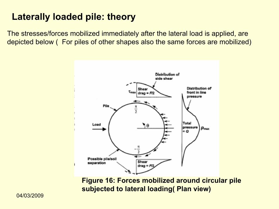
Laterally loaded pile: theoryThe stresses/forces mobilized immediately after the lateral load is applied, are depicted below ( For piles of other shapes also the same forces are mobilized)
Figure 16: Forces mobilized around circular pile subjected to lateral loading( Plan view)

04/03/2009
As shown in the Figure 7, the plane x-z is assumed to be the principal plane of the pile cross section. Due to the moment ‘Mo’ and shear ‘Vo’applied at the pile head, each point on the pile undergoes a translation ‘u’ in the x-direction and rotation θ about y-axis.
The surrounding soil develops pressures ‘p’ at each point to resist the lateral displacement ‘u’ of the pile.
The principles of continuum mechanics and correlations with the results of tests on instrumented laterally loaded piles were used to relate ‘u’ at each point with corresponding ‘p’. The relationship between ‘p’ and ‘u’is presented as non-linear curve famously known as p-u curve (in some literature referred as p-y curve).
All p-u curves are developed for monotonically increasing static loads and the static curve is then altered by various techniques to account for degradation effects due to cyclic loading

04/03/2009
A general method for moments, shear forces and displacements for a vertical pile embedded in a granular soil and subjected to moment and shear at the ground surface as shown in Figure 7 was given by Matlock and Resse(1960). The following are the equations proposed by them based on theory of beam on elastic foundation

04/03/2009
Simplified solution
Broms (1965) developed a simplified solution for ultimate lateral resistance of piles based on the following assumptions.
• shear failure of surrounding soil (in case of rigid piles)• bending of the pile by plastic yield resistance of pile section ( in case of flexible piles)
Broms’s solutions for ultimate resistance of rigid and flexible piles are shown in the next slide

04/03/2009
(b)
sand
claysand clay
(a)
Broms’s solution for ultimate resistance of rigid piles (a) and flexible piles (b)
Figure 17

04/03/2009
Uplift Capacity of Piles
The major components resisting uplift forces on pile foundation are skin friction and self weight of the pile. ( refer Figure 8)
So the governing equation for uplift capacity is
Quplift = fs As + Weight of the pile
Frictional resistance

04/03/2009
The capacity of the pile (Axial/Lateral/Uplift) either arrived by field approach or theoretical approach is called Ultimate capacity which is divided with a factor to arrive at safe carrying capacity of the pile.
The ultimate capacity is usually dictated by the limitations on settlements as per local engineering codes
The main purpose of under reporting the pile capacity by dividing it with a factor of safety is to accommodate various un certainties in•Soil strata•Loading and•Possible reduction in strength of sub soil strata due to installation technique, etc.

04/03/2009
Pile groups• Most pile foundations contain group of piles instead of single pile• The supporting capacity of a group of ‘n’ similar piles in many
cases (not in all cases) is ≤ ‘n’ times the capacity of a single pile-reason being the zone of soil or rock stressed by the entire group extends to much greater width and depth than that by a single pile as shown in the figure
Figure 18

04/03/2009
Analysis of pile groupsThere are three methods commonly used to analyze pile group:
•Simple static analysis: This method ignores the presence of soil and assumes pile group as an isolated structural system. It also assumes zero moment at the head of each pile.
•Equivalent bent analysis: This method considers the soil sub grade reaction on the equivalent free standing length of the piles. The pile cap is assumed to be rigid and piles are assumed to behave elastically.
•Elastic continuum analysis: The soil is considered as elastic material that is consistent through out its mass.

04/03/2009
In comparing various methods of analysis, the vertical loads are similar, but elastic continuum method predicts higher maximum load.The equivalent bent method which ignores presence of soil predicts higher pile rotations/moments than elastic continuum method.
Pile group efficiency factor(η) is usually calculated using any of the following six methods
1) Converse labarre’s method
Where, ‘ni’ represents no. of rows and columns ‘d’ is the dia of the pile and ‘s’c/c spacing between adjacent piles.

04/03/2009
2) Feld’s rule: reduces the capacity of each pile by 0.0625 for each adjacent pile. The spacing of piles is not considered.
3) Contractor’s rule: The pile capacity is reduced by a factor I for each adjacent pile where I =d/8s
4) Sand’s rule: Used for pile carried through friction in sand
5) Los Angles group action method:
6) Seiler- Keeney method:

04/03/2009
04/03/2009
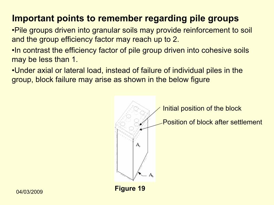
Important points to remember regarding pile groups•Pile groups driven into granular soils may provide reinforcement to soil and the group efficiency factor may reach up to 2.•In contrast the efficiency factor of pile group driven into cohesive soils may be less than 1.•Under axial or lateral load, instead of failure of individual piles in the group, block failure may arise as shown in the below figure
Initial position of the block
Position of block after settlement
Figure 19

04/03/2009
• independent calculations showing the capacity of block or groupof pile and capacity of individual piles should be made
• Relate the ultimate capacity of the block to sum of ultimate capacities of individual piles in the group i.e. find the ratio of ultimate capacity of block to sum of ultimate capacities of all piles in the group. This ratio should not be preferably less than 1
Ultimate Axial Capacity Ultimate capacity of pile group is usually the smaller of a) Ultimate capacity = m x n ( ultimate capacity of single pile in the group)
where m= no. of rows and n= no. of columns in the group (in plan view)
b) Ultimate capacity = L * B *(unit bearing resistance) + 2*(L+B) *Unit frictional resistance
Where L& B are plan dimensions of imaginary block encircling the pile group
Note the above formulae are based on the assumption that the line of action of loading coincides with the C.G of the group (i.e no moments)

04/03/2009
Ultimate Uplift Capacity
Figure 20
where Tg is the combined uplift capacity of group and Ti sum of uplift capacities of all individual piles

04/03/2009
Ultimate Lateral capacity
There are two common problems in the analysis of pile groups subjected to lateral loading1.The computation of loads coming on to each pile in the group and2.The computation of efficiency of group of closely spaced piles.
The ultimate lateral capacity, unlike axial capacity, of pile group cannot be presented as a simple equation due to the mathematical difficulty in establishing a proper relationship between the following INTERACTING FACTORS in addition to those associated with determining the lateral capacity of single pile.
Stiffness and density of soil in front of the pile cap Depth of cap embedment in the soilRotational restraint at the pile head by virtue of its embedment into the pile capPile group axial capacityStiffness and density of soil around the pilesLocation of Pile cap i.e. above or below soilCyclic and sustained loads
However, an analytical method called Group Equivalent Pile (GEP) method can be used with considerable accuracy for developing p-u curves for pile cap and piles in the group. In GEP, p-ucurves are obtained by multiplying the ‘p’ values of single pile with a modification factor to account forinteraction effects and summing the modified ‘p’ values of all piles in the group to obtain p-u curves for the group

04/03/2009
Factors influencing pile capacities• The surrounding soil
• installation technique like driven or bored
•Method of construction ( pre cast or cast in situ)
•Spacing of piles in a group
•Symmetry of the group
•Location of pile cap i.e. above or below soil
•Shape of the pile cap, etc.
•Location of pile in the group
•Drainage conditions in soil
Go through references given at the end of presentation to learn about theoretical determination of pile capacities due to the reasons mentioned above

04/03/2009
Settlement AnalysisPiles are subjected to the settlement due to the vertical loads coming
on to them from the structure supported by them.
The total settlement of a single pile has the following components
•Elastic settlement of the pile (se1)•Settlement of the pile caused by the load at the pile tip(se2)•Settlement of the pile caused by load transfer along the pile shaft (se3).
The formulae for calculating the above –mentioned settlements are given in the next slide

04/03/2009
pp
wswp
EALQQ
se)(
1ξ+
=s
wpwp
EIDq
se)1(
22µ−
=
S
wssws
LEIDQ
seρ
µ )1(3
2−=
Where,
Qwp = load carried at the pile tip resting on the soil, under working load condition
Qws = load carried by skin friction under working load condition
L= Length of the pile
Ep = Modulus of elasticity of pile material
Ap = Area of cross section of pile material
qwp = load at pile tip per unit area
µs = poissons ratio of the soil
Iwp Iws = influence factors

04/03/2009
Settlement of pile groups

04/03/2009 Figure 21

04/03/2009

04/03/2009
Design StepsDesign of pile foundation involves the following steps
1)Calculating the ultimate and then safe carrying capacity of pile of given material for a given soil data using the theoretical methods or obtaining the above-mentioned capacity from field test.
2)Arriving at the number of piles required for a given loading from the structure by considering the group effects on piles.
3)Designing the pile cap, which is usually considered as rigid member in a pile group.

04/03/2009
4) Calculating the distribution of forces , from the superstructure, in the piles and ensuring that the force on any pile in a group doesn’t exceed its safe carrying capacity.
5) Finally carrying out settlement analysis to ensure that the settlements are within the limits
Note: There are several mathematical procedures for calculating the capacity in various kinds of soil viz. cohesive, granular, and cohesive-granular and also to calculate the capacity based on method of installation i.e. driven or bored. Please refer the literature given in the references at the end to understand the procedures.

04/03/2009
2.SPECIAL TOPICS

04/03/2009
Negative Skin FrictionWhat is negative skin friction?
Negative skin friction is a downward shear drag acting on the pile surface due to relative downward movement of soil strata surrounding the pile.
The following are some of the causes of negative skin friction•Due to pile or pile segment passing through compressible soil stratum which consolidates
•Due to placement of a fill on compressible soil layer causing the layer to consolidate
•Lowering of ground water table causing the shrinkage of expansive soils.
•Under consolidated natural or compacted soils.
If the pile tip is on a stiff or hard stratum, there will be a relative downward movement of upper compressible layer of soil w.r.t. pile , due to above causes, causing a downward drag force.

04/03/2009
Initial position of compressible deposit
final position of compressible deposit
Downward drag( negative skin friction) Figure 22
•Vesic stated that downward movement as little as 0.6 inch may be sufficient to mobilize full negative skin friction.
•The down drag will not affect the geotechnical capacity of end-bearing piles but will increase stresses on the pile and pile cap.
The negative skin friction of a single pile is given byNegative skin friction load = Unit frictional resistance (downward)* Length of the pile above bottom of the compressible layer * Perimeter of the pile cross section
And total downward load= negative skin friction load + live load + dead load

04/03/2009
For a pile group it can be assumed that there is no relative movement between the piles and the soil between the piles. Therefore the total force acting down is equal to the weight of the block of soil held between the piles, the weight of the piles and the pile cap and the downward drag along the pile group perimeter due to negative skin friction
Pheripheral downdrag
A
SEC A
Figure 23

04/03/2009
Socketed Piles
What are socketed piles?Socketed piles are usually end bearing piles which are socketed into a weathered/soft rock.
What is weathered rock?
•Soil consolidates to Rock•Rock weathers to Soil
The in between phase of the above two is called as weathered rock /soft rock

04/03/2009
Pile Socketed into weathered rock
Pile
Sand
Stiff clay
Murum
Soft/ weathered rockSocket length
Soil over burden
Solid rockPile Tip
H
M
Figure 24

04/03/2009
Why socketing?
The common belief is socketing pile into a soft or weathered rock will improve the capacities of piles to lateral loads when the surrounding soil above the rock is weak.
The depth of socket is designed based on
•Local experience/empirical formulae: Usually a socket of depth varying from 2 to 5 times the diameter of the pile.
•By a more systematic approach called COLE and STROUD approach ( is not discussed here as it out of scope of this presentation)

04/03/2009
Dynamic testing of Piles
Dynamic pile testing is fast and effective method for assessing bearing capacity of the foundation that requires instrumenting deep foundations with accelerometers and strain transducers and analyzing the data collected by these transducers.
The Procedure is standardized by ASTM D 4945 ( Standard test method for high strain dynamic testing of piles.
The testing in addition to bearing capacity gives shaft resistance and point bearing resistance distribution and also evaluates the shape and integrity (please refer pile integrity in this presentation for more details) of the foundation
04/03/2009
•Dynamic pile testing is a supplement to static testing for evaluating pile capacity.
•The Dynamic pile testing is categorized as ---- High strain dynamic testing and------Low strain dynamic testing
High strain dynamic testing is used to provide data on force andacceleration of pile subjected to impact force. The data is used to evaluate the bearing capacity/capacity and structural integrity of the pile as well as hammer performance, pile stresses and soil characteristics like soil damping coefficients. Pile integrity which is accurately evaluated on site will allow the engineer to immediately reject or accept the pile.
Low strain pile testing is exclusively used for testing integrity ( continuity of pile). It also gives information on physical dimension and consistency of the pile material.

04/03/2009
Setup to produce impact on the pile
Data collector and Analyzer called pile driving analyzer ( PDA)
Figure 25:Dynamic pile testing setup

04/03/2009
Another picture showing setup for dynamic pile testing
Figure 26
04/03/2009
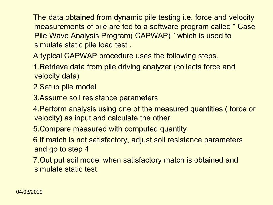
The data obtained from dynamic pile testing i.e. force and velocity measurements of pile are fed to a software program called “ Case Pile Wave Analysis Program( CAPWAP) “ which is used to simulate static pile load test .A typical CAPWAP procedure uses the following steps.1.Retrieve data from pile driving analyzer (collects force and velocity data)2.Setup pile model3.Assume soil resistance parameters4.Perform analysis using one of the measured quantities ( force orvelocity) as input and calculate the other.5.Compare measured with computed quantity6.If match is not satisfactory, adjust soil resistance parameters and go to step 47.Out put soil model when satisfactory match is obtained and simulate static test.

04/03/2009
Pile integrity testingWhat is pile integrity testing?A pile integrity test also known as low strain dynamic testing is used to check•Potentially dangerous defects such non uniform cross section, voids, cracks, etc in the casted pile foundation.•Integrity of pile in its total length.•To determine unknown length of pile in existing structures
04/03/2009
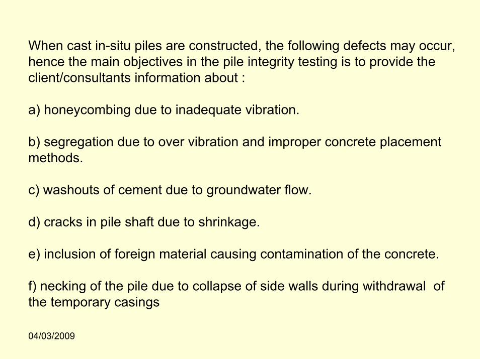
When cast in-situ piles are constructed, the following defects may occur, hence the main objectives in the pile integrity testing is to provide the client/consultants information about :
a) honeycombing due to inadequate vibration.
b) segregation due to over vibration and improper concrete placement methods.
c) washouts of cement due to groundwater flow.
d) cracks in pile shaft due to shrinkage.
e) inclusion of foreign material causing contamination of the concrete.
f) necking of the pile due to collapse of side walls during withdrawal of the temporary casings

04/03/2009
Dynamic loading on piles
The following are the most common situations in which piles are subjected to dynamic loading
•Pile driving
•Piles supporting dynamic equipment
•Earthquake

04/03/2009
Pile driving
•Usually ‘Driven’ piles are driven into the ground by impact force which causes considerable stresses in the piles.
•The forces and accelerations induced in the pile during driving are recorded using a data logger called Pile Driving Analyzer( PDA).
•The data obtained by PDA will be used to study the pile integrity and potentially dangerous defects like honey combing, cracks, presence of foreign matter, etc.
•The PDA works on the principles of wave propagation.

04/03/2009
Piles supporting dynamic equipment.Piles supporting dynamic equipment are usually subjected to impact and periodic forces which act continuously for a long time. This results in a complex soil- structure problem which calls for a rigorous analysis. Foundation for dynamic equipment is its self a research area. To give a preliminary idea some figures are presented below.
Machine(rotating, reciprocating or impact type)
Pile cap
Figure 27:Machine on pile foundation
Contd. Next slide

04/03/2009
Figure 28: Modes of vibration of machine which are transferred to the piles supporting the foundation
Researchers Novak, Donavan, Stevens, Indrajit Chowdhury, etc proposed simple but reliable solutions for the analysis of piles/pile groups subjected to dynamic loading.
Several researchers also proposed more complex and rigorous solutions using FEM techniques.

04/03/2009
Earthquake loading on piles.Earthquake loading is catastrophic for the pile foundation due to the fact that it induces very high lateral loading from the surrounding soil and the superstructure it carries causing a flexural failure of the pile due to its slenderness. Hence, this calls for a rigorous study of pile response to earthquake loading using complex mathematical/computational methods
Figure 29: Potential failure modes of pile foundations subjected to seismic loading

04/03/2009
3.PILE INSTALLATION

04/03/2009
Pile installation is as important as design. In this section, two types of methods:
a)Installation by Drivingb)Installation by Boring
Are presented in the subsequent slides

04/03/2009
Before going through pile installation methods understand the following terminology.
Driven pre-cast pile: The pile is casted in a yard brought to the site and driven by some mechanism into the soil
Driven Cast-in-situ pile: A casing plugged at bottom is driven into the ground and then the pile is casted by removing or retaining the casing
Bored Pre-cast pile: A bore is made and the soil inside is removed and then a pile casted in some yard is put into the bore
Bored Cast -in-situ pile: A bore is made the soil is removed and the pile is casted at site in the bore.

04/03/2009
Installation by Driving
•If the driving has to be carried out by hammer, the following factors should be take into consideration.
•The size and weight of the pile•The driving resistance which has to be overcome to achieve the desired penetration•The available space and head room in the site ( because the hammer has to be dropped from certain height and also the initial height is approximately height of the pile + height of fall of the hammer)•The availability of cranes•The noise restrictions which may be in force in the locality

04/03/2009
Schematics of pile driving with hammer
Drop hammer
Pile( pre cast) or Casing( cast-in-situ)
Driving shoe
Soil
Hammer guide
Figure 30

04/03/2009
Methods of pile driving• Dropping weight• Explosion• Vibration• Jacking ( only for micro piles)• Jetting
Figure 31: Hammer driven pile-real time

04/03/2009
Installation by Boring
Figure 32 : Installation by mechanical auger schematics

04/03/2009
Figure 33: Mechanical Auger-real time

04/03/2009
Figure 34: Rotary Bored Piling- real time

04/03/2009
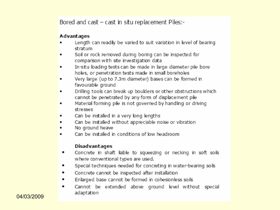
Advantages and Disadvantages of various piles

04/03/2009
04/03/2009

04/03/2009
4.MISCELLANEOUS

04/03/2009
Pile driving formulae
To develop the desired load carrying capacity, a point bearing driven pile must penetrate sufficiently into a dense soil layer or have sufficient contact with a layer of rock. This requirement cannot always be satisfied by driving a pile to a pre-determined depth, because soil profiles vary. For that reason several formulae have been developed to calculate the ultimate capacity of the pile during driving. They are based on Energy Approach and are independent of the soil into which pile is driven. Some of the formulae are given below. The reader is requested to go through literature suggested in references at the end. The famous of these formulae is Engineer’s news ( EN) record formula. The modified form of this formula is presented below
Qu = (E WR h)*(WR + n2WP) / ( S+C)*(WR +WP)
Contd. Next Slide

04/03/2009
Where,
Qu = Ultimate capacity of the pileWR = Weight of the ramh= height of fall of the ramWp= Weight of the pileC= a constantS=Penetration of pile per hammer blown= Coefficient of restitution between ram and pile capE= Efficiency of the hammer

04/03/2009
Pile cap configurations
Figure 35

04/03/2009Figure 36
04/03/2009
Structural Design of Pile and Pile cap
Structurally the pile section is designed as column for
•Compression plus Bending
•Tension plus bending
The pile cap is designed as rigid or flexible.
•A rigid ( very high flexural strength between two adjacent piles) pile cap is designed for one way shear and punching shear.
•A flexible ( average flexural strength between piles) pile cap is analyzed by FEM by considering the piles as vertical springs and then designed for the stresses obtained from the analysis

04/03/2009
Flow chart for pile selection
Figure 37

04/03/2009
Real time Pictures of Piles
Figure 38

04/03/2009
Figure 39

04/03/2009
5.ReferencesPlease refer the below books for detailed info on pile foundations.For purpose of industrial practice:•Principles of Foundation Engineering by B.M.Das•Foundation Analysis and Design by Joseph. E.Bowels•Foundation Design Manual for Practicing Engineers by Narayan.V.Naik•Foundation Design by Wayne.C.TengFor advanced information on the subject:•Pile foundation Analysis and Design by Poulus.H.G. and E.H.Davis•Foundation Design and Construction by Tomlinson.M.J.•Deep foundations by United Facility Criteria ( UFC) – US Army

04/03/2009
Thank You