Embed Size (px)
Citation preview
FAST DOME CAMERAPIH-7000/7600/7625 Series
INSTRUCTION MANUAL
MERIT LILIN ENT. CO., LTDhttp://www.meritlilin.com 66-7000CSE
CONTENTSPreface
Features
Warning & Cautions
Structural Element
Fast Dome Camera Set Up
Installation
System Configuration
Operation
DIP Switch Setting
Fan Switch
Alarm Mode
Fast Dome Function Switch
Fast Dome ID Address Setting Refer Chart
Fast Dome Connection Jack and Cable Requirement
Indoor Installation Structural Drawing (Embedded and Attached Mounting)
Outdoor Installation Structural Drawing (Pendant Mounting)
Embedded Mounting (False Ceiling)
Attached Mounting (Fixed Ceiling)
Pendant Mounting (External Housing)
Fast Dome and Keyboard
Fast Dome, Matrix and Keyboard
Fast Dome, DVR Multiplexer and Keyboard
Fast Dome with PC Control
Initial Power Up Inspection
Manual Operation
Fast Dome Pan/Tilt Control (Up, Down, Left, Right and Diagonal)
Fast Dome Selection
Zoom Lens Control
Focus Control
Iris Control
Horizontal 180 Instant Flip
Preset Position Setting
�
�
�
�
Selecting Fast Dome
Selecting Preset Position
Joystick Control
Adjusting Lens
1
............................................................................................................................
............................................................................................................................
.........................................................................................................
............................................................................................................
................................................................................................
.................................................
...............................................................
.........................................................................
..............
....................................
.......................................................................
....................................................................
.......................................................................................
............................................................................
............................................................
....................................................................................
....................................................................................
..................................................................................................
......................
.........................................................................................
...........................................................................................
..................................................................................................
......................................................................................................
Pages
....................................................................................................
....................................................................................................
..............................................................................
..............................................................................
............................................................................................
.....................................................................................
...............................................................................
.............................................................................................
...........................................................................................
Setting Preset Speed
Storing Preset Data
Recalling Preset Position
Setting Preset Position Group
Changing Preset Data
Activating AutoPan
Deleting Preset Data
Alarm Management
Alarm Response Mode
Alarm Output
Initial Setting (Factory Default)
AGC Control
Sensitivity Up (Enhancement)
Back Light Compensation
Back Light Compensation Zone
Flickerless
White Balance Mode
Gamma Adjustment (Brightness)
Pedestal Adjustment
Aperture Correction Adjustment
IR Cut (Filter) Selection
Private Mask
Operational
Camera
Optical Zoom Lens
Electrical
Environmental
Mechanical
External Housing
Quick Reference Table
Trouble Shooting
Installation Kit
Day & Night Fast Dome Function Setup (OSD Menu)
Specification
Appendix A
Appendix B
�
�
�
Setting Preset Dwell time
..............................................................................................
..............................................................................................
..............................................................................................
.................................................................................
..............................................................................................................
...........................................................................................................
.................................................................................................................
.................................................................................................
.......................................................................................................
...........................................................................................................
...................................................................................................
....................................................................................................................
.....................................................................................
.......................................................................................
............................................................................................
.......................................................................................
.................................................................................
...............................................................................................
....................................................................................................................
.......................................................................................
.............................................................................
........................................................................................................
..........................................................................................................
.............................................................................
.....................................................................................
............................................................................
..........................................................................
............................................................................................
............................................................................
............................................................................................
.......................................................................................
2
......................................................................................................
PREFACE
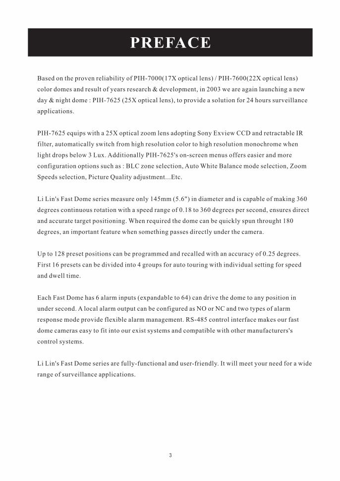
Based on the proven reliability of PIH-7000(17X optical lens) / PIH-7600(22X optical lens)
color domes and result of years research & development, in 2003 we are again launching a new
day & night dome : PIH-7625 (25X optical lens), to provide a solution for 24 hours surveillance
applications.
PIH-7625 equips with a 25X optical zoom lens adopting Sony Exview CCD and retractable IR
filter, automatically switch from high resolution color to high resolution monochrome when
light drops below 3 Lux. Additionally PIH-7625's on-screen menus offers easier and more
configuration options such as : BLC zone selection, Auto White Balance mode selection, Zoom
Speeds selection, Picture Quality adjustment...Etc.
Li Lin's Fast Dome series measure only 145mm (5.6") in diameter and is capable of making 360
degrees continuous rotation with a speed range of 0.18 to 360 degrees per second, ensures direct
and accurate target positioning. When required the dome can be quickly spun throught 180
degrees, an important feature when something passes directly under the camera.
Up to 128 preset positions can be programmed and recalled with an accuracy of 0.25 degrees.
First 16 presets can be divided into 4 groups for auto touring with individual setting for speed
and dwell time.
Each Fast Dome has 6 alarm inputs (expandable to 64) can drive the dome to any position in
under second. A local alarm output can be configured as NO or NC and two types of alarm
response mode provide flexible alarm management. RS-485 control interface makes our fast
dome cameras easy to fit into our exist systems and compatible with other manufacturers's
control systems.
Li Lin's Fast Dome series are fully-functional and user-friendly. It will meet your need for a wide
range of surveillance applications.
3
�
�
�
�
�
�
�
�
�
�
�
�
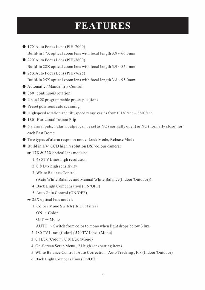
17X Auto Focus Lens (PIH-7000)
Build-in 17X optical zoom lens with focal length 3.9 ~ 66.3mm
22X Auto Focus Lens (PIH-7600)
Build-in 22X optical zoom lens with focal length 3.9 ~ 85.4mm
25X Auto Focus Lens (PIH-7625)
Build-in 25X optical zoom lens with focal length 3.8 ~ 95.0mm
Automatic / Manual Iris Control
360 continuous rotation
Up to 128 programmable preset positions
Preset positions auto scanning
Highspeed rotation and tilt, speed range varies from 0.18 /sec ~ 360 /sec
180 Horizontal Instant Flip
6 alarm inputs, 1 alarm output can be set as NO (normally open) or NC (normally close) for
each Fast Dome
Two types of alarm response mode: Lock Mode, Release Mode
Build in 1/4" CCD high resolution DSP colour camera:
17X & 22X optical lens models:
1. 480 TV Lines high resolution
2. 0.8 Lux high sensitivity
3. White Balance Control
(Auto White Balance and Manual White Balance(Indoor/Outdoor))
4. Back Light Compensation (ON/OFF)
5. Auto Gain Control (ON/OFF)
25X optical lens model:
1. Color / Mono Switch (IR Cut Filter)
ON Color
OFF Mono
AUTO Switch from color to mono when light drops below 3 lux.
2. 480 TV Lines (Color) ; 570 TV Lines (Mono)
3. 0.1Lux (Color) ; 0.01Lux (Mono)
4. On-Screen Setup Menu , 21 high sens setting items.
5. White Balance Control : Auto Correction , Auto Tracking , Fix (Indoor/Outdoor)
6. Back Light Compensation (On/Off)
�
�
FEATURES
4
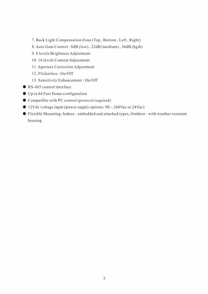
7. Back Light Compensation Zone (Top , Bottom , Left , Right)
8. Auto Gam Control : 8dB (low) , 22dB (medium) , 36dB (hgih)
9. 8 levels Brightness Adjustment
10. 16 levels Content Adjustment
11. Aperture Correction Adjustment
12. Flickerless : On/Off
13. Sensitivity Enhancement : On/Off
RS-485 control interface
Up to 64 Fast Dome configuration
Compatible with PC control (protocol required)
12Vdc voltage input (power supply options: 90 ~ 260Vac or 24Vac)
Flexible Mounting: Indoor - embedded and attached types, Outdoor - with weather resistant
housing
�
�
�
�
�
5
Please read the manual before attempting installation or operation
1. Please be aware to the warnings and cautions notice.
2. Don't use any chemical detergent to clean the machine surface, use a damp cotton cloth
only. Regularly clean the dome cover to assure proper focus ability.
3. Please install the Fast Dome in a dry area, water and high humidity may cause damage on
internal parts. External housing should be used for outdoor installation.
4. Please use parts supplied by the manufacturer only, any unqualified part using in the
equipment may violate the warranty.
5. Avoid installing the equipment in an unstable area. Make sure the area is firm and stable.
Falling equipment may injure personnel and damage the equipment.
6. Do not install the equipment near any flammable gas. Violation may cause fire or injury.
7. Avoid running video cable and signal cable through or passing interference sources such
as video waves, broadcast station, power generator, elevator motor or high voltage area
..... etc. Violation may cause interference.
8. Make sure the power cable is properly fixed. Un-suitably fixed cable may cause serious
short circuit or fire.
9. Correct cable connection is important. Do not place any object on the connection cable
and change the cable if there is damage on cable. Violation may cause short circuit, fire
and injury.
10. Make sure ground is well connected to avoid damage caused by lightning.
11. Do not put any foreign objects inside the equipment and do not spray any liquid on
equipment. This will avoid short circuit damage.
12. Do not touch power connection with wet hands to avoid short circuit or electricity shock.
13. Do not apply smash-force on the equipment. Violation may cause damage.
14. Do not install the equipment in a location that may expose the equipment directly to
sunlight. Violation may cause colour fading or damage.
15. Do not install the equipment in high temperature or low temperature environment to
avoid damage. The normal operational temperature is between -5 C ~ +50 C.
16. Fast Dome contains high sensitive electric parts inside. Do not try to repair them without
qualified personnel.
17. Turn off the power immediately and contact the technician when the following occurs:
A. Damage on power cable or plug.
B. Water leak into the equipment.
C. Fast Dome can not be operated normally.
D. Equipment falling on ground or damage on external case.
E. Unusual occurrence.
18. Warning: Do not try to repair the equipment. Only a qualified technician may disassemble
and repair the equipment. Shut off the power before disassemble the equipment and don't
put power on unless the case is completely assembled.
WARNINGS & CAUTIONS
6
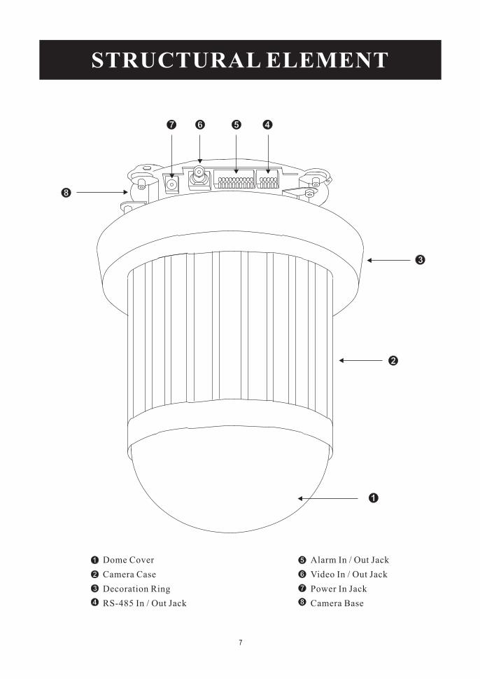
Dome Cover
Camera Case
Decoration Ring
RS-485 In / Out Jack
Alarm In / Out Jack
Video In / Out Jack
Power In Jack
Camera Base
STRUCTURAL ELEMENT
7
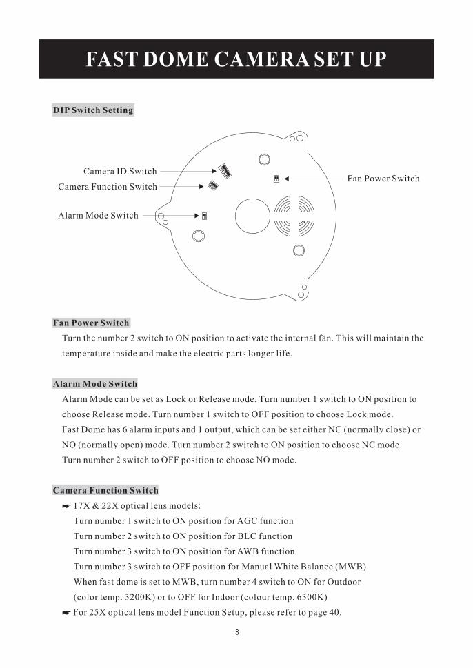
DIP Switch Setting
Fan Power Switch
Alarm Mode Switch
Camera Function Switch
Turn the number 2 switch to ON position to activate the internal fan. This will maintain the
temperature inside and make the electric parts longer life.
Alarm Mode can be set as Lock or Release mode. Turn number 1 switch to ON position to
choose Release mode. Turn number 1 switch to OFF position to choose Lock mode.
Fast Dome has 6 alarm inputs and 1 output, which can be set either NC (normally close) or
NO (normally open) mode. Turn number 2 switch to ON position to choose NC mode.
Turn number 2 switch to OFF position to choose NO mode.
17X & 22X optical lens models:
Turn number 1 switch to ON position for AGC function
Turn number 2 switch to ON position for BLC function
Turn number 3 switch to ON position for AWB function
Turn number 3 switch to OFF position for Manual White Balance (MWB)
When fast dome is set to MWB, turn number 4 switch to ON for Outdoor
(color temp. 3200K) or to OFF for Indoor (colour temp. 6300K)
For 25X optical lens model Function Setup, please refer to page 40.
�
�
Camera ID Switch
Camera Function Switch
Alarm Mode Switch
Fan Power Switch
FAST DOME CAMERA SET UP
8
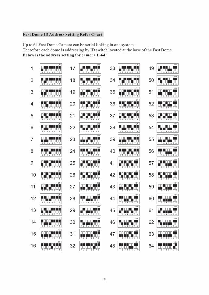
Fast Dome ID Address Setting Refer Chart
Below is the address setting for camera 1~64:
Up to 64 Fast Dome Camera can be serial linking in one system.
Therefore each dome is addressing by ID switch located at the base of the Fast Dome.
1 5432 76 8
ON
1 5432 76 8
ON
1
1
2 3 4 5
ON
86 7
5432 76 8
ON
ON
1
1
5432 76 8
2 3 4 5 86 7
ON
1
1
2 3 4 5
ON
86 7
5432 76 8
ON
76 854321
1 2 3 4 5
ON
86 7
ON
1
1
5432 76 8
ON
2 3 4 5 86 7
ON
1
1
5432
ON
76 8
2 3 4 5 86 7
ON
1
1
2 3 4 5
ON
86 7
5432 76 8
ON
1 2 3 4 5 86 7
1
1
5432 76 8
ON
5432
ON
76 8
1
1
ON
2 3 4 5 86 7
ON
5432
ON
76 8
1
1
1
86 72 3 4 5
2 3 4 5
ON
86 7
5432 76 8
ON
1
1
5432 76 8
ON
2 3 4 5
ON
86 7
1
1
ON
2 3 4 5
ON
86 7
5432
ON
76 8
1
1
1
76 85432
2 3 4 5
ON
86 7
5432 76 8
ON
1 2 3 4 5 86 7
ON
ON
1 2 3 4 5 86 7
1
1
5432 76 8
ON
5432
ON
76 8
1
1
ON
2 3 4 5 86 7
ON
5432
ON
76 8
1
1
1
86 72 3 4 5
2 3 4 5
ON
86 7
5432 76 8
ON
1
1
5432 76 8
ON
2 3 4 5
ON
86 7
1
1
ON
2 3 4 5
ON
86 7
5432
ON
76 8
1
1
1
76 85432
2 3 4 5
ON
86 7
5432 76 8
ON
1 2 3 4 5 86 7
ON
ON
1 5432 76 8
1
1
2 3 4 5
ON
86 7
2 3 4 5 86 7
ON
1
1
ON
5432
ON
76 8
2 3 4 5 86 7
ON
1
1
1
5432 76 8
5432 76 8
ON
2 3 4 5
ON
86 7
1
1
2 3 4 5
ON
86 7
5432 76 8
ON
1
1
ON
5432 76 8
ON
2 3 4 5 86 7
ON
1
1
1
2 3 4 5 86 7
5432 76 8
ON
2 3 4 5
ON
86 7
1 5432
ON
76 8
ON
17 33 491
2 18 34 50
5135193
5236204
5337215
5438226
5539237
5640248
64
63
62
61
60
57
59
58
48
47
46
45
44
41
43
42
32
31
30
29
28
25
27
26
16
15
14
13
12
9
11
10
9
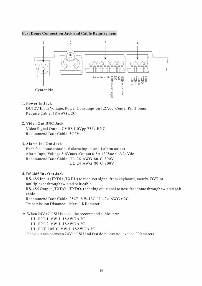
Fast Dome Connection Jack and Cable Requirement
1. Power In Jack
2. Video Out BNC Jack
3. Alarm In / Out Jack
4. RS-485 In / Out Jack
DC12V Input Voltage, Power Consumption 1.2Adc, Center Pin 2.0mm
Require Cable: 18 AWG x 2C
Video Signal Output CVBS 1.0Vpp 75 BNC
Recommend Data Cable: 5C2V
Each fast dome contains 6 alarm inputs and 1 alarm output
Alarm Input Voltage 5.6Vmax, Output 0.5A 120Vac / 1A 24Vdc
Recommend Data Cable: UL 26 AWG 80 C 300V
RS-485 Input (TXDI+,TXDI-) to receiver signal from keyboard, matrix, DVR or
multiplexer through twisted pair cable.
RS-485 Output (TXDO+,TXDO-) sending out signal to next fast dome through twisted pair
cable.
Recommend Data Cable: 2547 VW-ISC UL 24 AWG x 2C
Transmission Distance: Max. 1 Kilometer
When 24VAC PSU is used, the recommend cables are:
UL SPT-1 VW-1 18AWG x 2C
UL SPT-2 VW-1 18AWG x 2C
UL SUT 105 C VW-1 18AWG x 3C
The distance between 24Vac PSU and fast dome can not exceed 200 meters.
Center Pin
UL 24 AWG 80 C 300V
(Alarm
Input)
(Alarm
Output)
10
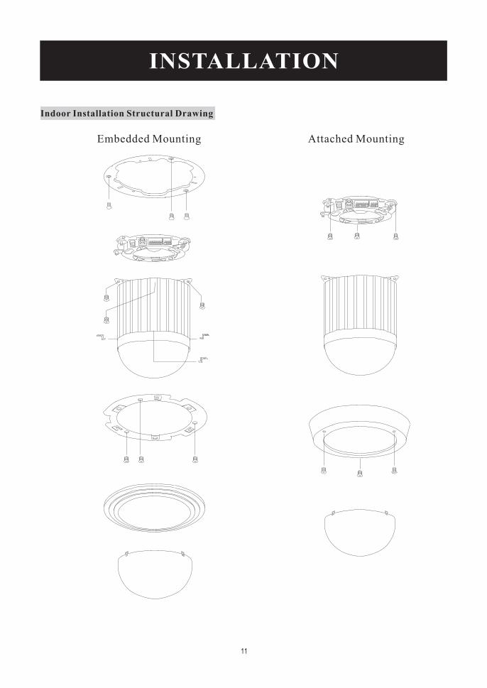
Indoor Installation Structural Drawing
Embedded Mounting Attached Mounting
INSTALLATION
11
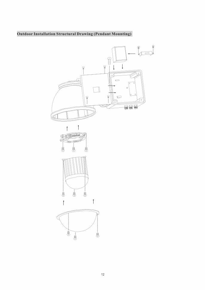
Outdoor Installation Structural Drawing (Pendant Mounting)
12
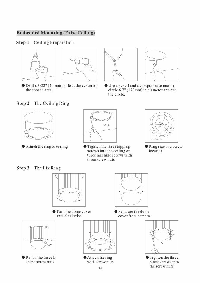
Embedded Mounting (False Ceiling)
� Drill a 3/32" (2.4mm) hole at the center ofthe chosen area.
� Use a pencil and a compasses to mark acircle 6.7" (170mm) in diameter and cutthe circle.
� Attach the ring to ceiling � Ring size and screwlocation
� Tighten the three tappingscrews into the ceiling orthree machine screws withthree screw nuts
� Turn the dome coveranti-clockwise
� Separate the domecover from camera
Step 1 Ceiling Preparation
Step 2 The Ceiling Ring
Step 3 The Fix Ring
13
� Put on the three Lshape screw nuts
� Tighten the threeblack screws intothe screw nuts
� Attach fix ringwith screw nuts
� Unplug theconnection cable
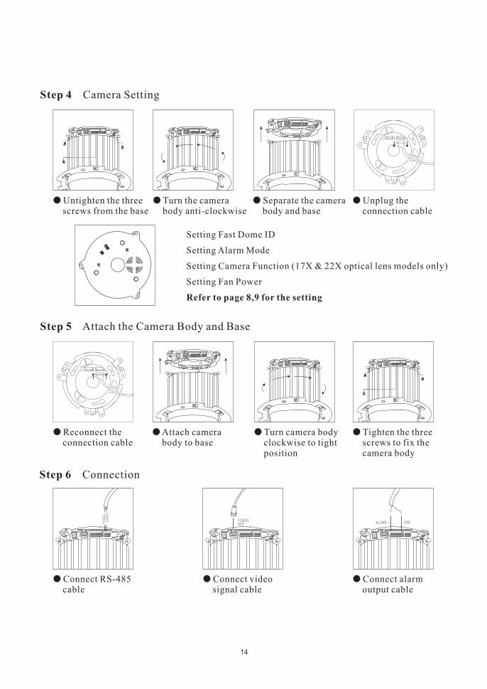
Setting Fast Dome ID
Setting Alarm Mode
Setting Camera Function (17X & 22X optical lens models only)
Setting Fan Power
Refer to page 8,9 for the setting
� Untighten the threescrews from the base
� Separate the camerabody and base
� Turn the camerabody anti-clockwise
� Reconnect theconnection cable
� Tighten the threescrews to fix thecamera body
� Attach camerabody to base
� Turn camera bodyclockwise to tightposition
Step 4 Camera Setting
Step 5 Attach the Camera Body and Base
14
� Connect RS-485cable
� Connect alarmoutput cable
� Connect videosignal cable
Step 6 Connection
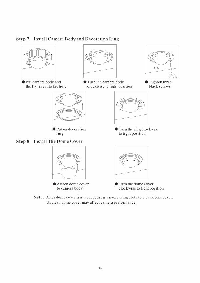
� Put on decorationring
� Turn the ring clockwiseto tight position
� Put camera body andthe fix ring into the hole
� Tighten threeblack screws
� Turn the camera bodyclockwise to tight position
� Attach dome coverto camera body
� Turn the dome coverclockwise to tight position
Step 7 Install Camera Body and Decoration Ring
Step 8 Install The Dome Cover
15
Note : After dome cover is attached, use glass-cleaning cloth to clean dome cover.
Unclean dome cover may affect camera performance.
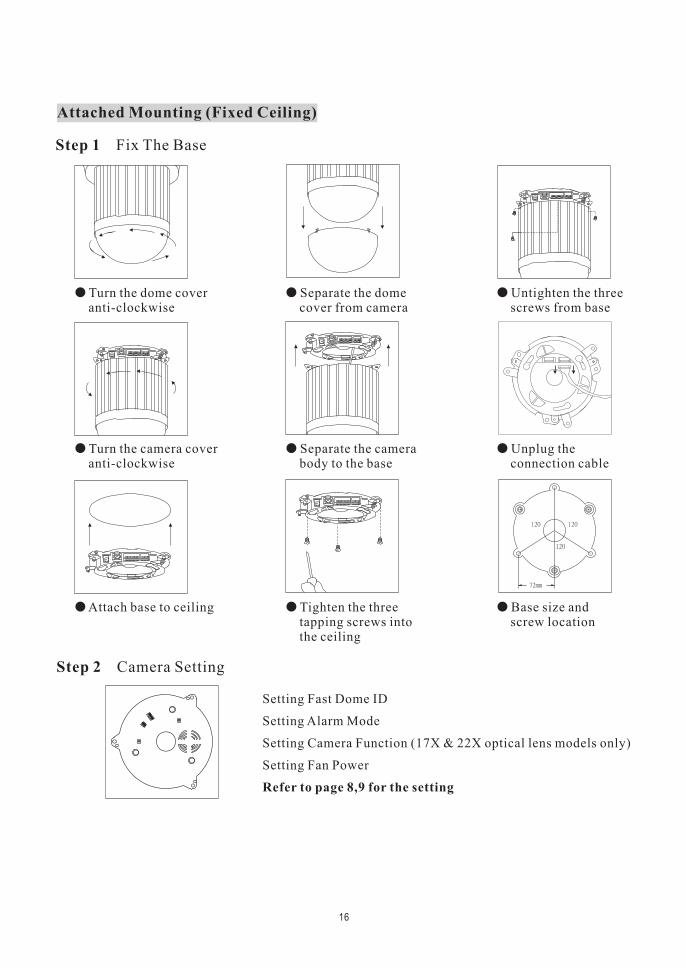
� Turn the dome coveranti-clockwise
� Untighten the threescrews from base
� Separate the domecover from camera
� Turn the camera coveranti-clockwise
� Unplug theconnection cable
� Separate the camerabody to the base
� Attach base to ceiling � Base size andscrew location
� Tighten the threetapping screws intothe ceiling
Attached Mounting (Fixed Ceiling)
Step 1 Fix The Base
Step 2 Camera Setting
Setting Fast Dome ID
Setting Alarm Mode
Setting Camera Function (17X & 22X optical lens models only)
Setting Fan Power
Refer to page 8,9 for the setting
16
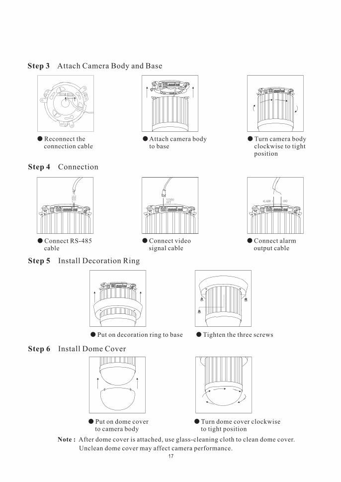
� Connect RS-485cable
� Connect alarmoutput cable
� Connect videosignal cable
� Reconnect theconnection cable
� Turn camera bodyclockwise to tightposition
� Attach camera bodyto base
� Put on decoration ring to base � Tighten the three screws
� Put on dome coverto camera body
� Turn dome cover clockwiseto tight position
Step 3 Attach Camera Body and Base
Step 4 Connection
Step 5 Install Decoration Ring
Step 6 Install Dome Cover
17
Note : After dome cover is attached, use glass-cleaning cloth to clean dome cover.
Unclean dome cover may affect camera performance.
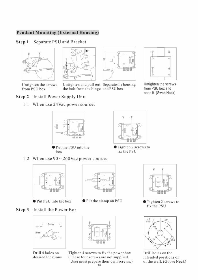
� Put the PSU into thebox
� Tighten 2 screws tofix the PSU
� Put PSU into the box � Put the clamp on PSU � Tighten 2 screws tofix the PSU
Pendant Mounting (External Housing)
Step 1 Separate PSU and Bracket
Step 2 Install Power Supply Unit
1.1 When use 24Vac power source:
1.2 When use 90 ~ 260Vac power source:
18
Step 3 Install the Power Box
Untighten the screwsfrom PSU box
Untighten and pull outthe bolt from the hinge
Separate the housingand PSU box
Untighten the screwsfrom PSU box andopen it. (Swan Neck)
Drill 4 holes ondesired locations
Tighten 4 screws to fix the power box(These four screws are not supplied.User must prepare their own screws.)
Drill holes on theintended positions ofof the wall. (Goose Neck)
70
7050.8
50.8
45108
GN
DN
ON
CC
OM654321
GN
DT
XD
O-
TX
DO
+T
XD
I-T
XD
I+
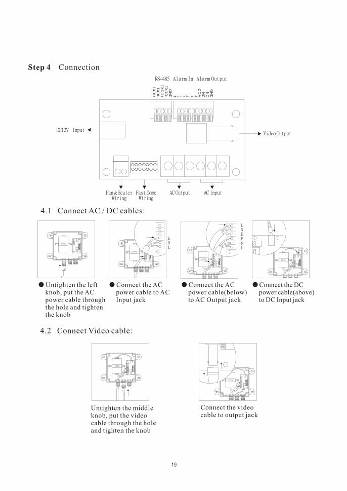
� Untighten the leftknob, put the ACpower cable throughthe hole and tightenthe knob
� Connect the ACpower cable to ACInput jack
� Connect the ACpower cable(below)to AC Output jack
� Connect the DCpower cable(above)to DC Input jack
Step 4 Connection
4.1 Connect AC / DC cables:
19
4.2 Connect Video cable:
Connect the videocable to output jack
Untighten the middleknob, put the videocable through the holeand tighten the knob
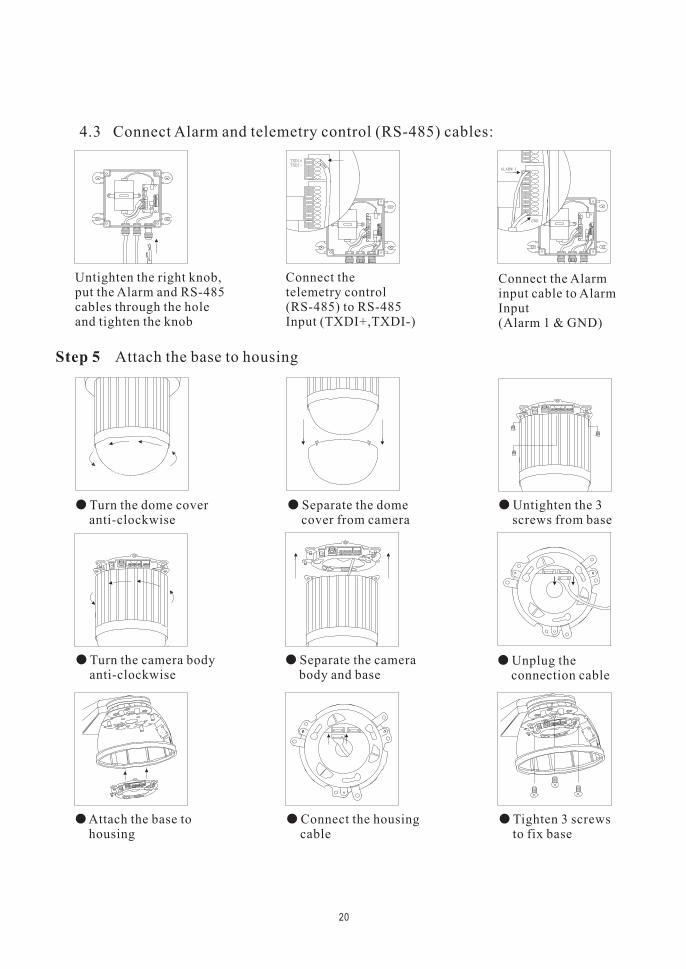
� Turn the dome coveranti-clockwise
� Separate the domecover from camera
� Untighten the 3screws from base
� Turn the camera bodyanti-clockwise
� Separate the camerabody and base
� Unplug theconnection cable
Step 5 Attach the base to housing
20
� Attach the base tohousing
� Connect the housingcable
� Tighten 3 screwsto fix base
4.3 Connect Alarm and telemetry control (RS-485) cables:
Untighten the right knob,put the Alarm and RS-485cables through the holeand tighten the knob
Connect thetelemetry control(RS-485) to RS-485Input (TXDI+,TXDI-)
Connect the Alarminput cable to AlarmInput(Alarm 1 & GND)
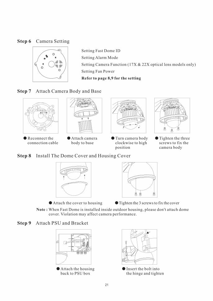
� Reconnect theconnection cable
� Attach camerabody to base
� Turn camera bodyclockwise to highposition
� Tighten the threescrews to fix thecamera body
Step 7 Attach Camera Body and Base
21
� Attach the cover to housing � Tighten the 3 screws to fix the cover
� Attach the housingback to PSU box
� Insert the bolt intothe hinge and tighten
Step 8 Install The Dome Cover and Housing Cover
Step 9 Attach PSU and Bracket
Note : When Fast Dome is installed inside outdoor housing, please don't attach domecover. Violation may affect camera performance.
Setting Fast Dome ID
Setting Alarm Mode
Setting Camera Function (17X & 22X optical lens models only)
Setting Fan Power
Refer to page 8,9 for the setting
Step 6 Camera Setting
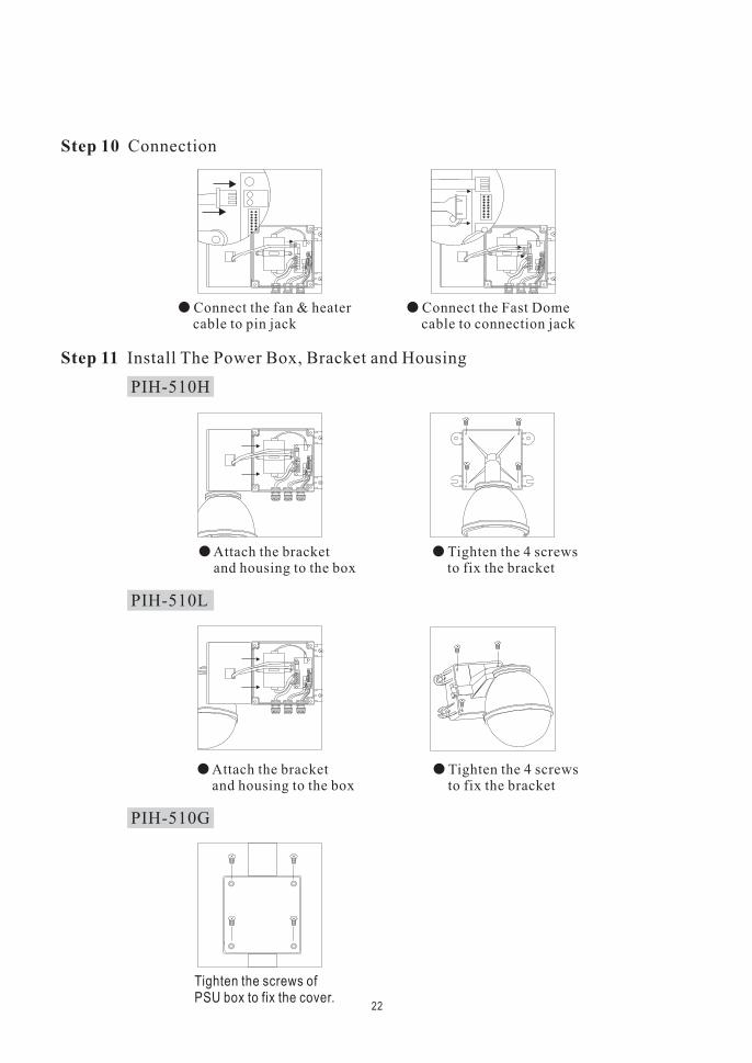
� Attach the bracketand housing to the box
� Tighten the 4 screwsto fix the bracket
� Attach the bracketand housing to the box
� Tighten the 4 screwsto fix the bracket
Step 11 Install The Power Box, Bracket and Housing
PIH-510H
22
� Connect the fan & heatercable to pin jack
� Connect the Fast Domecable to connection jack
Step 10 Connection
Tighten the screws ofPSU box to fix the cover.
PIH-510L
PIH-510G
Li Lin's integrated Fast Dome Surveillance System is suitable for a wide range of surveillance
applications. The system cam be as single fast dome with one keyboard or encompassing as 64
domes with comprehensive matrix switching, PC control and even Digital Video Recording.
Such flexibility means future expansion is easily facilitated.
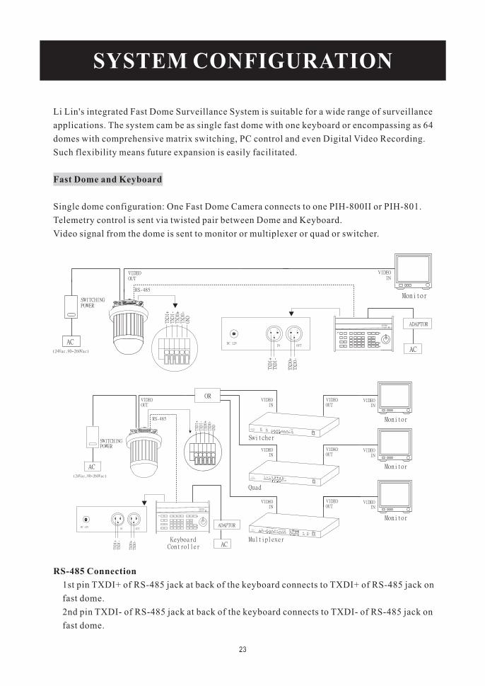
Single dome configuration: One Fast Dome Camera connects to one PIH-800II or PIH-801.
Telemetry control is sent via twisted pair between Dome and Keyboard.
Video signal from the dome is sent to monitor or multiplexer or quad or switcher.
Fast Dome and Keyboard
23
RS-485 Connection
1st pin TXDI+ of RS-485 jack at back of the keyboard connects to TXDI+ of RS-485 jack on
fast dome.
2nd pin TXDI- of RS-485 jack at back of the keyboard connects to TXDI- of RS-485 jack on
fast dome.
SYSTEM CONFIGURATION
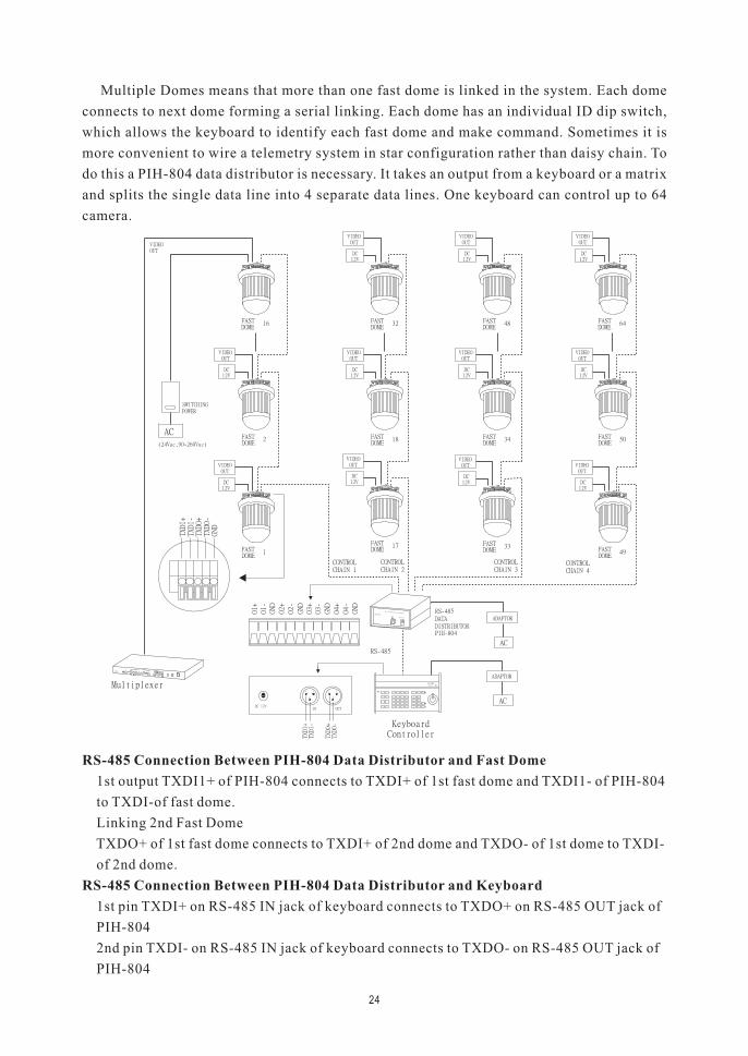
Multiple Domes means that more than one fast dome is linked in the system. Each dome
connects to next dome forming a serial linking. Each dome has an individual ID dip switch,
which allows the keyboard to identify each fast dome and make command. Sometimes it is
more convenient to wire a telemetry system in star configuration rather than daisy chain. To
do this a PIH-804 data distributor is necessary. It takes an output from a keyboard or a matrix
and splits the single data line into 4 separate data lines. One keyboard can control up to 64
camera.
RS-485 Connection Between PIH-804 Data Distributor and Fast Dome
RS-485 Connection Between PIH-804 Data Distributor and Keyboard
1st output TXDI1+ of PIH-804 connects to TXDI+ of 1st fast dome and TXDI1- of PIH-804
to TXDI-of fast dome.
Linking 2nd Fast Dome
TXDO+ of 1st fast dome connects to TXDI+ of 2nd dome and TXDO- of 1st dome to TXDI-
of 2nd dome.
1st pin TXDI+ on RS-485 IN jack of keyboard connects to TXDO+ on RS-485 OUT jack of
PIH-804
2nd pin TXDI- on RS-485 IN jack of keyboard connects to TXDO- on RS-485 OUT jack of
PIH-804
24
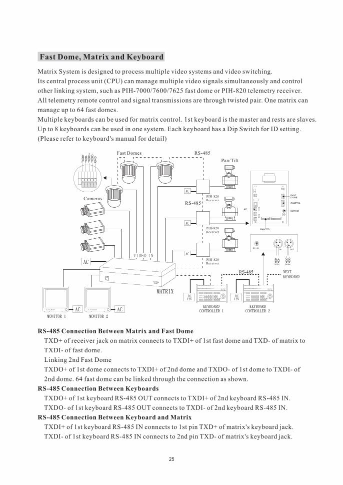
Matrix System is designed to process multiple video systems and video switching.
Its central process unit (CPU) can manage multiple video signals simultaneously and control
other linking system, such as PIH-7000/7600/7625 fast dome or PIH-820 telemetry receiver.
All telemetry remote control and signal transmissions are through twisted pair. One matrix can
manage up to 64 fast domes.
Multiple keyboards can be used for matrix control. 1st keyboard is the master and rests are slaves.
Up to 8 keyboards can be used in one system. Each keyboard has a Dip Switch for ID setting.
(Please refer to keyboard's manual for detail)
RS-485 Connection Between Matrix and Fast Dome
RS-485 Connection Between Keyboards
RS-485 Connection Between Keyboard and Matrix
TXD+ of receiver jack on matrix connects to TXDI+ of 1st fast dome and TXD- of matrix to
TXDI- of fast dome.
Linking 2nd Fast Dome
TXDO+ of 1st dome connects to TXDI+ of 2nd dome and TXDO- of 1st dome to TXDI- of
2nd dome. 64 fast dome can be linked through the connection as shown.
TXDO+ of 1st keyboard RS-485 OUT connects to TXDI+ of 2nd keyboard RS-485 IN.
TXDO- of 1st keyboard RS-485 OUT connects to TXDI- of 2nd keyboard RS-485 IN.
TXDI+ of 1st keyboard RS-485 IN connects to 1st pin TXD+ of matrix's keyboard jack.
TXDI- of 1st keyboard RS-485 IN connects to 2nd pin TXD- of matrix's keyboard jack.
Fast Domes
Cameras
Pan/Tilt
PIH-820Receiver
1 3
2
1 3
2
DC 12VIN OUT
TX
DI+
TX
DI-
TX
DO
-
TX
DO
+
TX
DI+
TX
DI-
TX
DO
-
TX
DO
+
GN
D
RS-485
FASTDOME
CAMERA
MATRIX
PAN/TITL
AC
MATRIXPIH-864
POWERF1 F2
F4F3 1
PRESET1 PRESET2
FASTPRESET3
2 3 SETUP
MON654
CAM987
ENT0CLR PRESET
ESC AUX CTRL2CTRL1AUTO
SPRAYWIPER
SEQ
ZOOM
IN
FAR
FOUCS
IRIS
O
NEAR
OUT
PAN
RESET
ALARM
ZOOM
FOUCS
IRIS
C
AUTO
AUTO
FOUCS
IRIS
KEYPROPIH-800
POWERF1 F2
F4F3 1
PRESET1 PRESET2
FASTPRESET3
2 3 SETUP
MON654
CAM987
ENT0CLR PRESET
ESC AUX CTRL2CTRL1AUTO
SPRAYWIPER
SEQ
ZOOM
IN
FAR
FOUCS
IRIS
O
NEAR
OUT
PAN
RESET
ALARM
ZOOM
FOUCS
IRIS
C
AUTO
AUTO
FOUCS
IRIS
KEYPROPIH-800
RS-485
RS-485
PIH-820Receiver
PIH-820Receiver
Fast Dome, Matrix and Keyboard
25
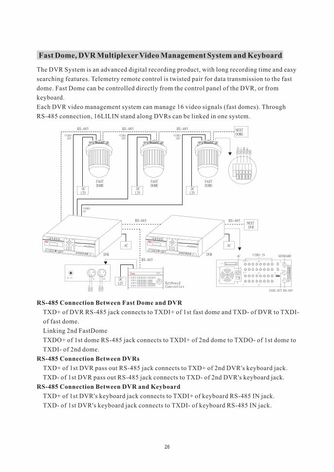
RS-485 Connection Between Fast Dome and DVR
RS-485 Connection Between DVRs
RS-485 Connection Between DVR and Keyboard
TXD+ of DVR RS-485 jack connects to TXDI+ of 1st fast dome and TXD- of DVR to TXDI-
of fast dome.
Linking 2nd FastDome
TXDO+ of 1st dome RS-485 jack connects to TXDI+ of 2nd dome to TXDO- of 1st dome to
TXDI- of 2nd dome.
TXD+ of 1st DVR pass out RS-485 jack connects to TXD+ of 2nd DVR's keyboard jack.
TXD- of 1st DVR pass out RS-485 jack connects to TXD- of 2nd DVR's keyboard jack.
TXD+ of 1st DVR's keyboard jack connects to TXDI+ of keyboard RS-485 IN jack.
TXD- of 1st DVR's keyboard jack connects to TXDI- of keyboard RS-485 IN jack.
Fast Dome, DVR Multiplexer Video Management System and Keyboard
The DVR System is an advanced digital recording product, with long recording time and easy
searching features. Telemetry remote control is twisted pair for data transmission to the fast
dome. Fast Dome can be controlled directly from the control panel of the DVR, or from
keyboard.
Each DVR video management system can manage 16 video signals (fast domes). Through
RS-485 connection, 16LILIN stand along DVRs can be linked in one system.
26
TX
DI+
TX
DI-
TX
DO
-
TX
DO
+
GN
D
TX
DI+
TX
DI-
TX
DO
-
TX
DO
+
GN
D
TX
DI+
TX
DI-
TX
DO
-
TX
DO
+
GN
D
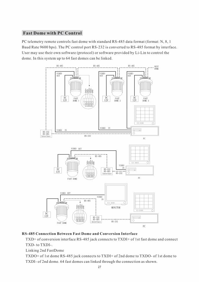
RS-485 Connection Between Fast Dome and Conversion Interface
TXD+ of conversion interface RS-485 jack connects to TXDI+ of 1st fast dome and connect
TXD- to TXDI-.
Linking 2nd FastDome
TXDO+ of 1st dome RS-485 jack connects to TXDI+ of 2nd dome to TXDO- of 1st dome to
TXDI- of 2nd dome. 64 fast domes can linked through the connection as shown.
Fast Dome with PC Control
PC telemetry remote controls fast dome with standard RS-485 data format (format: N, 8, 1
Baud Rate 9600 bps). The PC control port RS-232 is converted to RS-485 format by interface.
User may use their own software (protocol) or software provided by Li-Lin to control the
dome. In this system up to 64 fast domes can be linked.
27
1
2
3
4
5
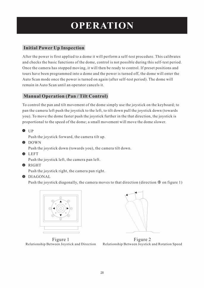
Figure 1Relationship Between Joystick and Direction
Figure 2Relationship Between Joystick and Rotation Speed
OPERATION
Initial Power Up Inspection
After the power is first applied to a dome it will perform a self-test procedure. This calibrates
and checks the basic functions of the dome, control is not possible during this self-test period.
Once the camera has stopped moving, it will then be ready to control. If preset positions and
tours have been programmed into a dome and the power is turned off, the dome will enter the
Auto Scan mode once the power is turned on again (after self-test period). The dome will
remain in Auto Scan until an operator cancels it.
Manual Operation (Pan / Tilt Control)
To control the pan and tilt movement of the dome simply use the joystick on the keyboard; to
pan the camera left push the joystick to the left, to tilt down pull the joystick down (towards
you). To move the dome faster push the joystick further in the that direction, the joystick is
proportional to the speed of the dome; a small movement will move the dome slower.
UP
Push the joystick forward, the camera tilt up.
DOWN
Push the joystick down (towards you), the camera tilt down.
LEFT
Push the joystick left, the camera pan left.
RIGHT
Push the joystick right, the camera pan right.
DIAGONAL
Push the joystick diagonally, the camera moves to that direction (direction on figure 1)
28
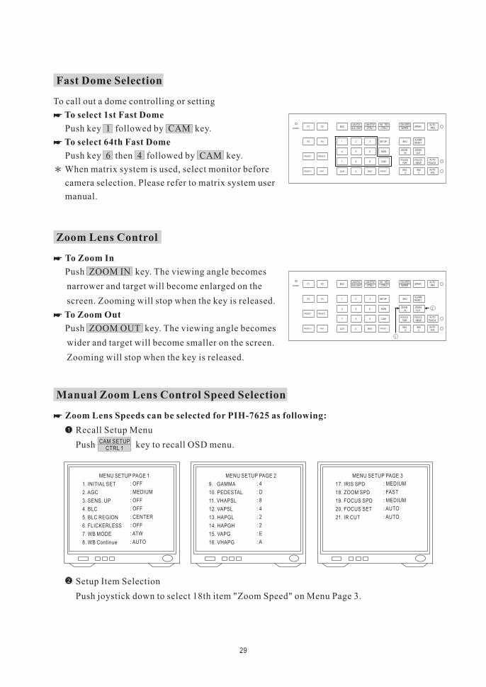
Fast Dome Selection
To call out a dome controlling or setting
Push key 1 followed by CAM key.
Push key 6 then 4 followed by CAM key.
When matrix system is used, select monitor before
camera selection. Please refer to matrix system user
manual.
To select 1st Fast Dome
To select 64th Fast Dome
�
�
Zoom Lens Control
To Zoom In
To Zoom Out
Push ZOOM IN key. The viewing angle becomes
narrower and target will become enlarged on the
screen. Zooming will stop when the key is released.
Push ZOOM OUT key. The viewing angle becomes
wider and target will become smaller on the screen.
Zooming will stop when the key is released.
�
�
29
POWERF1 F2
F4F3 1
PRESET1 PRESET2
FASTPRESET3
2 3 SETUP
MON654
CAM987
ENT0CLR PRESET
ESCAUX LIGHT CTRL2CTRL1
AUTOSPRAY
WIPER
SEQ
ZOOMIN
FARFOUCS
IRISO
NEAR
OUT
PAN
RESETALARM
ZOOM
FOUCS
IRISC
AUTO
AUTO
FOUCS
IRIS
CAM ESC 180 REVCAM SETUP LENS SPEED
POWERF1 F2
F4F3 1
PRESET1 PRESET2
FASTPRESET3
2 3 SETUP
MON654
CAM987
ENT0CLR PRESET
ESCAUX LIGHT CTRL2CTRL1
AUTOSPRAY
WIPER
SEQ
ZOOMIN
FARFOUCS
IRISO
NEAR
OUT
PAN
RESETALARM
ZOOM
FOUCS
IRISC
AUTO
AUTO
FOUCS
IRIS
CAM ESC 180 REVCAM SETUP LENS SPEED
Manual Zoom Lens Control Speed Selection
Zoom Lens Speeds can be selected for PIH-7625 as following:
Recall Setup Menu
Push key to recall OSD menu.
�
1
CAM SETUPCTRL 1
MENU SETUP PAGE 1
1. INITIAL SET
2. AGC
3. SENS. UP
4. BLC
5. BLC REGION
6. FLICKERLESS
7. WB MODE
8. WB Continue
: OFF
: MEDIUM
: OFF
: OFF
: CENTER
: OFF
: ATW
: AUTO
MENU SETUP PAGE 2
9. GAMMA
10. PEDESTAL
11. VHAPSL
12. VAPSL
13. HAPGL
14. HAPGH
15. VAPG
16. VHAPG
: 4
: D
: 8
: 4
: 2
: 2
: E
: A
MENU SETUP PAGE 3
17. IRIS SPD
18. ZOOM SPD
19. FOCUS SPD
20. FOCUS SET
21. IR CUT
: MEDIUM
: FAST
: MEDIUM
: AUTO
: AUTO
Setup Item Selection
Push joystick down to select 18th item "Zoom Speed" on Menu Page 3.
2
30
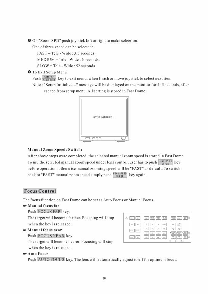
On "Zoom SPD" push joystick left or right to make selection.
One of three speed can be selected:
FAST = Tele - Wide : 3.5 seconds.
MEDIUM = Tele - Wide : 6 seconds.
SLOW = Tele - Wide : 52 seconds.
To Exit Setup Menu
Push key to exit menu, when finish or move joystick to select next item.
Note : "Setup Initialize..." message will be displayed on the monitor for 4~5 seconds, after
escape from setup menu. All setting is stored in Fast Dome.
After above steps were completed, the selected manual zoom speed is stored in Fast Dome.
To use the selected manual zoom speed under lens control, user has to push key
before operation, otherwise manual zooming speed will be "FAST" as default. To switch
back to "FAST" manual zoom speed simply push key again.
Manual Zoom Speeds Switch:
CAM ESCAUX LIGHT
3
SETUP INITIALIZE......
LENS SPEEDWIPER
LENS SPEEDWIPER
4
Focus Control
The focus function on Fast Dome can be set as Auto Focus or Manual Focus.
Push FOCUS FAR key.
The target will become farther. Focusing will stop
when the key is released.
Push FOCUS NEAR key.
The target will become nearer. Focusing will stop
when the key is released.
Manual focus far
Manual focus near
Push AUTO FOCUS key. The lens will automatically adjust itself for optimum focus.
Auto Focus
�
�
�
POWERF1 F2
F4F3 1
PRESET1 PRESET2
FASTPRESET3
2 3 SETUP
MON654
CAM987
ENT0CLR PRESET
ESCAUX LIGHT CTRL2CTRL1
AUTOSPRAY
WIPER
SEQ
ZOOMIN
FARFOUCS
IRISO
NEAR
OUT
PAN
RESETALARM
ZOOM
FOUCS
IRISC
AUTO
AUTO
FOUCS
IRIS
CAM ESC 180 REVCAM SETUP LENS SPEED
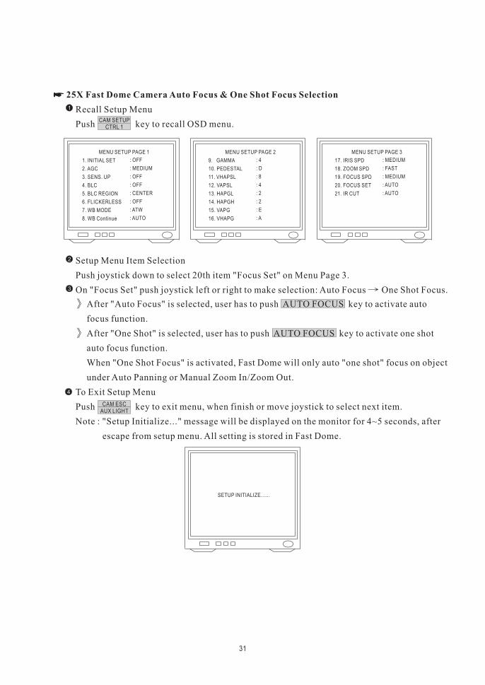
Recall Setup Menu
Push key to recall OSD menu.
Setup Menu Item Selection
Push joystick down to select 20th item "Focus Set" on Menu Page 3.
On "Focus Set" push joystick left or right to make selection: Auto Focus One Shot Focus.
� 25X Fast Dome Camera Auto Focus & One Shot Focus Selection
31
1
CAM SETUPCTRL 1
MENU SETUP PAGE 1
1. INITIAL SET
2. AGC
3. SENS. UP
4. BLC
5. BLC REGION
6. FLICKERLESS
7. WB MODE
8. WB Continue
: OFF
: MEDIUM
: OFF
: OFF
: CENTER
: OFF
: ATW
: AUTO
MENU SETUP PAGE 2
9. GAMMA
10. PEDESTAL
11. VHAPSL
12. VAPSL
13. HAPGL
14. HAPGH
15. VAPG
16. VHAPG
: 4
: D
: 8
: 4
: 2
: 2
: E
: A
MENU SETUP PAGE 3
17. IRIS SPD
18. ZOOM SPD
19. FOCUS SPD
20. FOCUS SET
21. IR CUT
: MEDIUM
: FAST
: MEDIUM
: AUTO
: AUTO
2
3
After "Auto Focus" is selected, user has to push AUTO FOCUS key to activate auto
focus function.
After "One Shot" is selected, user has to push AUTO FOCUS key to activate one shot
auto focus function.
When "One Shot Focus" is activated, Fast Dome will only auto "one shot" focus on object
under Auto Panning or Manual Zoom In/Zoom Out.
To Exit Setup Menu
Push key to exit menu, when finish or move joystick to select next item.
Note : "Setup Initialize..." message will be displayed on the monitor for 4~5 seconds, after
escape from setup menu. All setting is stored in Fast Dome.
CAM ESCAUX LIGHT
4
SETUP INITIALIZE......
32
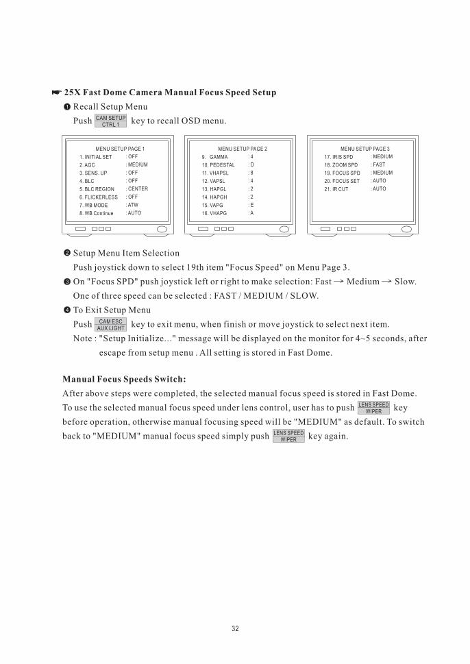
Recall Setup Menu
Push key to recall OSD menu.
Setup Menu Item Selection
Push joystick down to select 19th item "Focus Speed" on Menu Page 3.
On "Focus SPD" push joystick left or right to make selection: Fast Medium Slow.
One of three speed can be selected : FAST / MEDIUM / SLOW.
To Exit Setup Menu
Push key to exit menu, when finish or move joystick to select next item.
Note : "Setup Initialize..." message will be displayed on the monitor for 4~5 seconds, after
escape from setup menu . All setting is stored in Fast Dome.
� 25X Fast Dome Camera Manual Focus Speed Setup
1
CAM SETUPCTRL 1
MENU SETUP PAGE 1
1. INITIAL SET
2. AGC
3. SENS. UP
4. BLC
5. BLC REGION
6. FLICKERLESS
7. WB MODE
8. WB Continue
: OFF
: MEDIUM
: OFF
: OFF
: CENTER
: OFF
: ATW
: AUTO
MENU SETUP PAGE 2
9. GAMMA
10. PEDESTAL
11. VHAPSL
12. VAPSL
13. HAPGL
14. HAPGH
15. VAPG
16. VHAPG
: 4
: D
: 8
: 4
: 2
: 2
: E
: A
MENU SETUP PAGE 3
17. IRIS SPD
18. ZOOM SPD
19. FOCUS SPD
20. FOCUS SET
21. IR CUT
: MEDIUM
: FAST
: MEDIUM
: AUTO
: AUTO
2
3
CAM ESCAUX LIGHT
4
After above steps were completed, the selected manual focus speed is stored in Fast Dome.
To use the selected manual focus speed under lens control, user has to push key
before operation, otherwise manual focusing speed will be "MEDIUM" as default. To switch
back to "MEDIUM" manual focus speed simply push key again.
Manual Focus Speeds Switch:
LENS SPEEDWIPER
LENS SPEEDWIPER
POWERF1 F2
F4F3 1
PRESET1 PRESET2
FASTPRESET3
2 3 SETUP
MON654
CAM987
ENT0CLR PRESET
ESCAUX LIGHT CTRL2CTRL1
AUTOSPRAY
WIPER
SEQ
ZOOMIN
FARFOUCS
IRISO
NEAR
OUT
PAN
RESETALARM
ZOOM
FOUCS
IRISC
AUTO
AUTO
FOUCS
IRIS
CAM ESC 180 REVCAM SETUP LENS SPEED
33
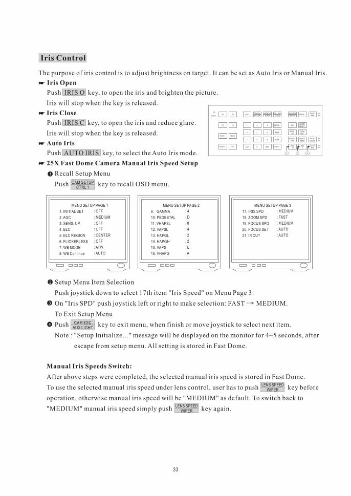
Iris Control
The purpose of iris control is to adjust brightness on target. It can be set as Auto Iris or Manual Iris.
Push IRIS O key, to open the iris and brighten the picture.
Iris will stop when the key is released.
Push IRIS C key, to open the iris and reduce glare.
Iris will stop when the key is released.
Push AUTO IRIS key, to select the Auto Iris mode.
Iris Open
Iris Close
Auto Iris
�
�
�
Recall Setup Menu
Push key to recall OSD menu.
� 25X Fast Dome Camera Manual Iris Speed Setup
1
CAM SETUPCTRL 1
MENU SETUP PAGE 1
1. INITIAL SET
2. AGC
3. SENS. UP
4. BLC
5. BLC REGION
6. FLICKERLESS
7. WB MODE
8. WB Continue
: OFF
: MEDIUM
: OFF
: OFF
: CENTER
: OFF
: ATW
: AUTO
MENU SETUP PAGE 2
9. GAMMA
10. PEDESTAL
11. VHAPSL
12. VAPSL
13. HAPGL
14. HAPGH
15. VAPG
16. VHAPG
: 4
: D
: 8
: 4
: 2
: 2
: E
: A
MENU SETUP PAGE 3
17. IRIS SPD
18. ZOOM SPD
19. FOCUS SPD
20. FOCUS SET
21. IR CUT
: MEDIUM
: FAST
: MEDIUM
: AUTO
: AUTO
Setup Menu Item Selection
Push joystick down to select 17th item "Iris Speed" on Menu Page 3.
On "Iris SPD" push joystick left or right to make selection: FAST MEDIUM.
To Exit Setup Menu
Push key to exit menu, when finish or move joystick to select next item.
Note : "Setup Initialize..." message will be displayed on the monitor for 4~5 seconds, after
escape from setup menu. All setting is stored in Fast Dome.
2
CAM ESCAUX LIGHT
3
4
After above steps were completed, the selected manual iris speed is stored in Fast Dome.
To use the selected manual iris speed under lens control, user has to push key before
operation, otherwise manual iris speed will be "MEDIUM" as default. To switch back to
"MEDIUM" manual iris speed simply push key again.
Manual Iris Speeds Switch:
LENS SPEEDWIPER
LENS SPEEDWIPER
34
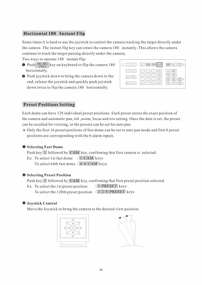
Horizontal 180 Instant Flip
Some times it is hard to use the joystick to control the camera tracking the target directly under
the camera. The instant flip key can rotate the camera 180 instantly. This allows the camera
continue to track the target passing directly under the camera.
Two ways to operate 180 instant flip:
Push key on keyboard to flip the camera 180
horizontally.
Push joystick down to bring the camera down to the
end, release the joystick and quickly push joystick
down twice to flip the camera 180 horizontally.
1180 REV
CTRL 2
2
POWERF1 F2
F4F3 1
PRESET1 PRESET2
FASTPRESET3
2 3 SETUP
MON654
CAM987
ENT0CLR PRESET
ESCAUX LIGHT CTRL2CTRL1
AUTOSPRAY
WIPER
SEQ
ZOOMIN
FARFOUCS
IRISO
NEAR
OUT
PAN
RESETALARM
ZOOM
FOUCS
IRISC
AUTO
AUTO
FOUCS
IRIS
CAM ESC 180 REVCAM SETUP LENS SPEED
Preset Positions Setting
Each dome can have 128 individual preset positions. Each preset stores the exact position of
the camera and automatic pan, tilt ,zoom, focus and iris setting. Once the data is set, the preset
can be recalled for viewing, or the presets can be set for auto pan.
Only the first 16 preset positions of fast dome can be set to auto pan mode and first 6 preset
positions are corresponding with the 6 alarm inputs.
Push key 1 followed by CAM key, confirming that first camera is selected.
Ex. To select 1st fast dome
To select 64th fast dome
Push key 1 followed by CAM key, confirming that first preset position selected.
Ex. To select the 1st preset position
To select the 128th preset position
Selecting Fast Dome
Selecting Preset Position
�
�
: 1 CAM keys
: 6 4 CAM keys
1
2
: 1 PRESET keys
: 1 2 8 PRESET keys
Move the Joystick to bring the camera to the desired view position.
Joystick Control3
35
4
ZOOM IN / OUT, FOCUS NEAR / FAR / AUTO and IRIS O / C / AUTO keys.
When set up preset point, using manual focus will provide both clarity and stability of image.
Adjusting Lens
POWERF1 F2
F4F3 1
PRESET1 PRESET2
FASTPRESET3
2 3 SETUP
MON654
CAM987
ENT0CLR PRESET
ESCAUX LIGHT CTRL2CTRL1
AUTOSPRAY
WIPER
SEQ
ZOOMIN
FARFOUCS
IRISO
NEAR
OUT
PAN
RESETALARM
ZOOM
FOUCS
IRISC
AUTO
AUTO
FOUCS
IRIS
CAM ESC 180 REVCAM SETUP LENS SPEED
POWERF1 F2
F4F3 1
PRESET1 PRESET2
FASTPRESET3
2 3 SETUP
MON654
CAM987
ENT0CLR PRESET
ESCAUX LIGHT CTRL2CTRL1
AUTOSPRAY
WIPER
SEQ
ZOOMIN
FARFOUCS
IRISO
NEAR
OUT
PAN
RESETALARM
ZOOM
FOUCS
IRISC
AUTO
AUTO
FOUCS
IRIS
CAM ESC 180 REVCAM SETUP LENS SPEED
5
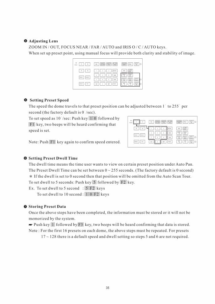
The speed the dome travels to that preset position can be adjusted between 1 to 255 per
second (the factory default is 0 /sec).
To set speed as 10 /sec: Push key 1 0 followed by
F1 key, two beeps will be heard confirming that
speed is set.
Note: Push F1 key again to confirm speed entered.
Setting Preset Speed
The dwell time means the time user wants to view on certain preset position under Auto Pan.
The Preset Dwell Time can be set between 0 ~ 255 seconds. (The factory default is 0 second)
If the dwell is set to 0 second then that position will be omitted from the Auto Scan Tour.
To set dwell to 5 seconds: Push key 5 followed by F2 key.
Ex. To set dwell to 5 second
To set dwell to 10 second
Setting Preset Dwell Time�
: 5 F2 keys
: 1 0 F2 keys
6
Once the above steps have been completed, the information must be stored or it will not be
memorized by the system.
Push key 1 followed by F3 key, two beeps will be heard confirming that data is stored.
Note : For the first 16 presets on each dome, the above steps must be repeated. For presets
17 ~ 128 there is a default speed and dwell setting so steps 5 and 6 are not required.
Storing Preset Data
�
�7
36
Recalling Preset Positions
Once the required preset positions have been stored in a dome, they may be quickly recalled,
returning the dome to exact position.
To recall 1st Preset Position: Push key 1 followed by PRESET key.
The dome will move to that position in speed of 360 /sec.
Ex. To recall 1st preset position
To recall 128th preset position
�
: 1 PRESET keys
: 1 2 8 PRESET keys
1 F4
1 2 F4
3 4 F4
1 2 3 F4
2 3 4 F4
1 2 3 4 F4
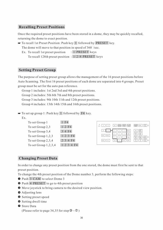
Setting Preset Group
The purpose of setting preset group allows the management of the 16 preset positions before
Auto Scanning. The first 16 preset positions of each dome are separated into 4 groups. Preset
group must be set for the auto pan reference.
Group 1 includes: 1st 2nd 3rd and 4th preset positions.
Group 2 includes: 5th 6th 7th and 8th preset positions.
Group 3 includes: 9th 10th 11th and 12th preset positions.
Group 4 includes: 13th 14th 15th and 16th preset positions.
To set up group 1: Push key 1 followed by F4 key.
Ex.
To set Group 1
To set Group 2,3
To set Group 3,4
To set Group 1,2,3
To set Group 2,3,4
To set Group 1,2,3,4
�
POWERF1 F2
F4F3 1
PRESET1 PRESET2
FASTPRESET3
2 3 SETUP
MON654
CAM987
ENT0CLR PRESET
ESCAUX LIGHT CTRL2CTRL1
AUTOSPRAY
WIPER
SEQ
ZOOMIN
FARFOUCS
IRISO
NEAR
OUT
PAN
RESETALARM
ZOOM
FOUCS
IRISC
AUTO
AUTO
FOUCS
IRIS
CAM ESC 180 REVCAM SETUP LENS SPEED
1
2
3
4
5
6
7
Changing Preset Data
In order to change any preset position from the one stored, the dome must first be sent to that
preset position.
To change the 4th preset position of the Dome number 3, perform the following steps:
Push 3 CAM to select Dome 3
Push 4 PRESET to go to 4th preset position
Move joystick to bring camera to the desired view position.
Adjusting lens
Setting preset speed
Setting dwell time
Store Data
(Please refer to page 34,35 for step ~ )
Activating Auto Pan
When the Auto Pan function is activated, the fast dome will auto touring the preset groups entered.
Push AUTO PAN key, confirming the activation of
autopan.
Push AUTO PAN key again, confirming the stop of
autopan.
If the AUTO PAN is activated, no other commands can be sent to that dome, but other dome
can still be selected and operated manually.
Simply push the numeric key followed by the CAM key.
Push key 2 followed by CAM key, confirming the 2nd camera is selected.
To activate Auto Pan:
To stop Auto Pan:
To select (call out) another dome while it is under Auto Pan mode:
�
�
�
(Auto Pan Led will be lit.)
(Auto Pan Led will be Off.)
37
POWERF1 F2
F4F3 1
PRESET1 PRESET2
FASTPRESET3
2 3 SETUP
MON654
CAM987
ENT0CLR PRESET
ESCAUX LIGHT CTRL2CTRL1
AUTOSPRAY
WIPER
SEQ
ZOOMIN
FARFOUCS
IRISO
NEAR
OUT
PAN
RESETALARM
ZOOM
FOUCS
IRISC
AUTO
AUTO
FOUCS
IRIS
CAM ESC 180 REVCAM SETUP LENS SPEED
POWERF1 F2
F4F3 1
PRESET1 PRESET2
FASTPRESET3
2 3 SETUP
MON654
CAM987
ENT0CLR PRESET
ESCAUX LIGHT CTRL2CTRL1
AUTOSPRAY
WIPER
SEQ
ZOOMIN
FARFOUCS
IRISO
NEAR
OUT
PAN
RESETALARM
ZOOM
FOUCS
IRISC
AUTO
AUTO
FOUCS
IRIS
CAM ESC 180 REVCAM SETUP LENS SPEED
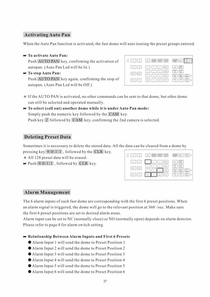
Deleting Preset Data
Sometimes it is necessary to delete the stored data. All the data can be cleared from a dome by
pressing key 9 0 1 1 , followed by the CLR key.
All 128 preset data will be erased.
Push 9 0 1 1 , followed by CLR key.�
The 6 alarm inputs of each fast dome are corresponding with the first 6 preset positions. When
an alarm signal is triggered, the dome will go to the relevant position at 360 /sec. Make sure
the first 6 preset positions are set to desired alarm areas.
Alarm input can be set to NC (normally close) or NO (normally open) depends on alarm detector.
Please refer to page 8 for alarm switch setting.
Alarm Input 1 will send the dome to Preset Position 1
Alarm Input 2 will send the dome to Preset Position 2
Alarm Input 3 will send the dome to Preset Position 3
Alarm Input 4 will send the dome to Preset Position 4
Alarm Input 5 will send the dome to Preset Position 5
Alarm Input 6 will send the dome to Preset Position 6
Relationship Between Alarm Inputs and First 6 Presets
�
�
�
�
�
�
�
Alarm Management
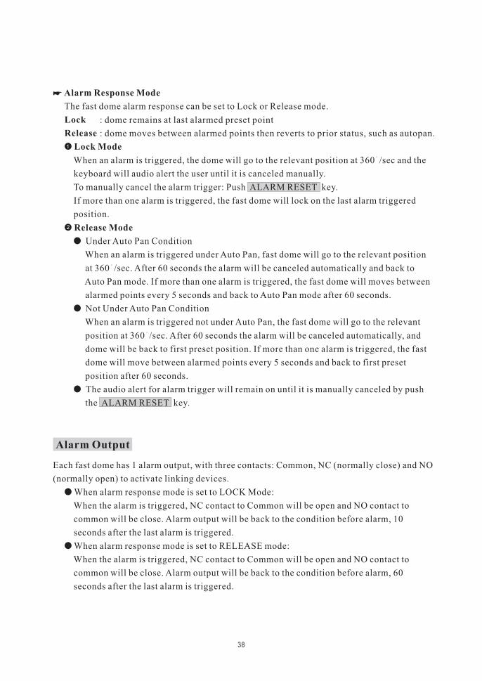
The fast dome alarm response can be set to Lock or Release mode.
When an alarm is triggered, the dome will go to the relevant position at 360 /sec and the
keyboard will audio alert the user until it is canceled manually.
To manually cancel the alarm trigger: Push ALARM RESET key.
If more than one alarm is triggered, the fast dome will lock on the last alarm triggered
position.
Alarm Response Mode
Lock
Release
Lock Mode
�
�1
: dome remains at last alarmed preset point
: dome moves between alarmed points then reverts to prior status, such as autopan.
38
Under Auto Pan Condition
When an alarm is triggered under Auto Pan, fast dome will go to the relevant position
at 360 /sec. After 60 seconds the alarm will be canceled automatically and back to
Auto Pan mode. If more than one alarm is triggered, the fast dome will moves between
alarmed points every 5 seconds and back to Auto Pan mode after 60 seconds.
Not Under Auto Pan Condition
When an alarm is triggered not under Auto Pan, the fast dome will go to the relevant
position at 360 /sec. After 60 seconds the alarm will be canceled automatically, and
dome will be back to first preset position. If more than one alarm is triggered, the fast
dome will move between alarmed points every 5 seconds and back to first preset
position after 60 seconds.
The audio alert for alarm trigger will remain on until it is manually canceled by push
the ALARM RESET key.
Release Mode�
�
�
�
2
Each fast dome has 1 alarm output, with three contacts: Common, NC (normally close) and NO
(normally open) to activate linking devices.
When alarm response mode is set to LOCK Mode:
When the alarm is triggered, NC contact to Common will be open and NO contact to
common will be close. Alarm output will be back to the condition before alarm, 10
seconds after the last alarm is triggered.
When alarm response mode is set to RELEASE mode:
When the alarm is triggered, NC contact to Common will be open and NO contact to
common will be close. Alarm output will be back to the condition before alarm, 60
seconds after the last alarm is triggered.
�
�
Alarm Output
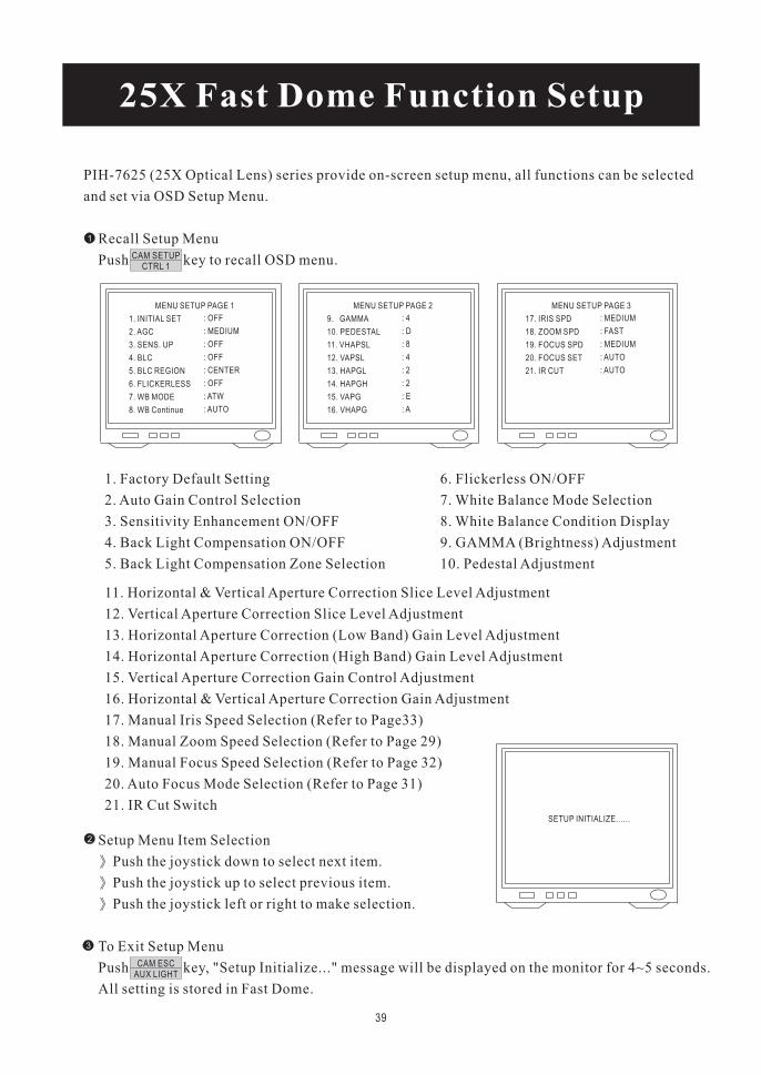
PIH-7625 (25X Optical Lens) series provide on-screen setup menu, all functions can be selected
and set via OSD Setup Menu.
Recall Setup Menu
Push key to recall OSD menu.
25X Fast Dome Function Setup
1
CAM SETUPCTRL 1
MENU SETUP PAGE 1
1. INITIAL SET
2. AGC
3. SENS. UP
4. BLC
5. BLC REGION
6. FLICKERLESS
7. WB MODE
8. WB Continue
: OFF
: MEDIUM
: OFF
: OFF
: CENTER
: OFF
: ATW
: AUTO
MENU SETUP PAGE 2
9. GAMMA
10. PEDESTAL
11. VHAPSL
12. VAPSL
13. HAPGL
14. HAPGH
15. VAPG
16. VHAPG
: 4
: D
: 8
: 4
: 2
: 2
: E
: A
MENU SETUP PAGE 3
17. IRIS SPD
18. ZOOM SPD
19. FOCUS SPD
20. FOCUS SET
21. IR CUT
: MEDIUM
: FAST
: MEDIUM
: AUTO
: AUTO
1. Factory Default Setting
2. Auto Gain Control Selection
3. Sensitivity Enhancement ON/OFF
4. Back Light Compensation ON/OFF
5. Back Light Compensation Zone Selection
6. Flickerless ON/OFF
7. White Balance Mode Selection
8. White Balance Condition Display
9. GAMMA (Brightness) Adjustment
10. Pedestal Adjustment
11. Horizontal & Vertical Aperture Correction Slice Level Adjustment
12. Vertical Aperture Correction Slice Level Adjustment
13. Horizontal Aperture Correction (Low Band) Gain Level Adjustment
14. Horizontal Aperture Correction (High Band) Gain Level Adjustment
15. Vertical Aperture Correction Gain Control Adjustment
16. Horizontal & Vertical Aperture Correction Gain Adjustment
17. Manual Iris Speed Selection (Refer to Page33)
18. Manual Zoom Speed Selection (Refer to Page 29)
19. Manual Focus Speed Selection (Refer to Page 32)
20. Auto Focus Mode Selection (Refer to Page 31)
21. IR Cut Switch
Setup Menu Item Selection
Push the joystick down to select next item.
Push the joystick up to select previous item.
Push the joystick left or right to make selection.
To Exit Setup Menu
Push key, "Setup Initialize..." message will be displayed on the monitor for 4~5 seconds.
All setting is stored in Fast Dome.
2
CAM ESCAUX LIGHT
3
SETUP INITIALIZE......
39
40
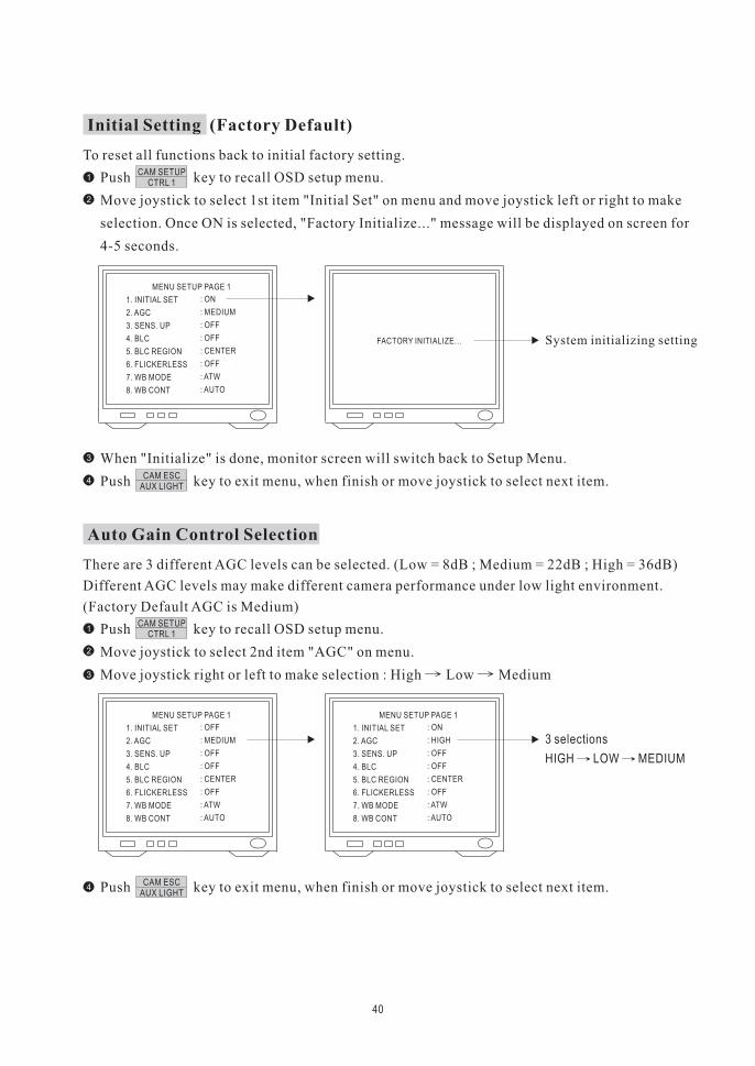
To reset all functions back to initial factory setting.
Push key to recall OSD setup menu.
Move joystick to select 1st item "Initial Set" on menu and move joystick left or right to make
selection. Once ON is selected, "Factory Initialize..." message will be displayed on screen for
4-5 seconds.
When "Initialize" is done, monitor screen will switch back to Setup Menu.
Push key to exit menu, when finish or move joystick to select next item.
1CAM SETUP
CTRL 1
CAM ESCAUX LIGHT
Initial Setting (Factory Default)
FACTORY INITIALIZE... System initializing setting
MENU SETUP PAGE 1
1. INITIAL SET
2. AGC
3. SENS. UP
4. BLC
5. BLC REGION
6. FLICKERLESS
7. WB MODE
8. WB CONT
: ON
: MEDIUM
: OFF
: OFF
: CENTER
: OFF
: ATW
: AUTO
2
3
4
There are 3 different AGC levels can be selected. (Low = 8dB ; Medium = 22dB ; High = 36dB)
Different AGC levels may make different camera performance under low light environment.
(Factory Default AGC is Medium)
Push key to recall OSD setup menu.
Move joystick to select 2nd item "AGC" on menu.
Move joystick right or left to make selection : High Low Medium
Push key to exit menu, when finish or move joystick to select next item.
1CAM SETUP
CTRL 1
CAM ESCAUX LIGHT
Auto Gain Control Selection
2
3
4
MENU SETUP PAGE 1
1. INITIAL SET
2. AGC
3. SENS. UP
4. BLC
5. BLC REGION
6. FLICKERLESS
7. WB MODE
8. WB CONT
: OFF
: MEDIUM
: OFF
: OFF
: CENTER
: OFF
: ATW
: AUTO
MENU SETUP PAGE 1
1. INITIAL SET
2. AGC
3. SENS. UP
4. BLC
5. BLC REGION
6. FLICKERLESS
7. WB MODE
8. WB CONT
: ON
: HIGH
: OFF
: OFF
: CENTER
: OFF
: ATW
: AUTO
3 selections
HIGH LOW MEDIUM
41
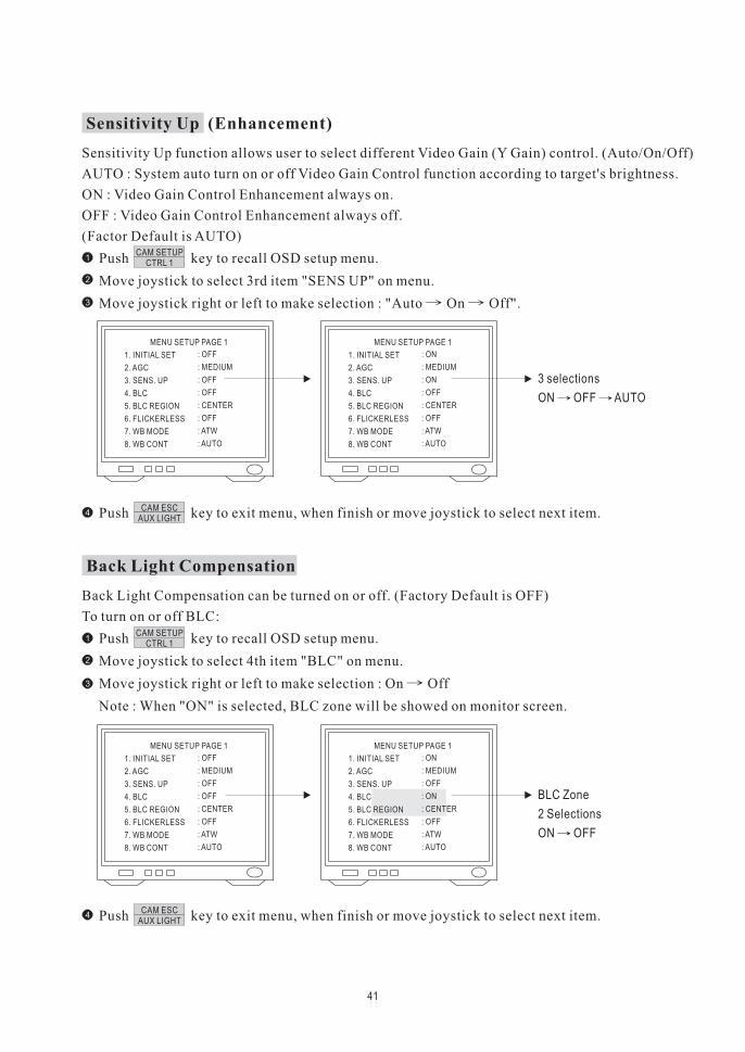
Sensitivity Up function allows user to select different Video Gain (Y Gain) control. (Auto/On/Off)
AUTO : System auto turn on or off Video Gain Control function according to target's brightness.
ON : Video Gain Control Enhancement always on.
OFF : Video Gain Control Enhancement always off.
(Factor Default is AUTO)
Push key to recall OSD setup menu.
Move joystick to select 3rd item "SENS UP" on menu.
Move joystick right or left to make selection : "Auto On Off".
Push key to exit menu, when finish or move joystick to select next item.
1CAM SETUP
CTRL 1
CAM ESCAUX LIGHT
Sensitivity Up (Enhancement)
2
3
4
Back Light Compensation can be turned on or off. (Factory Default is OFF)
To turn on or off BLC:
Push key to recall OSD setup menu.
Move joystick to select 4th item "BLC" on menu.
Move joystick right or left to make selection : On Off
Note : When "ON" is selected, BLC zone will be showed on monitor screen.
Push key to exit menu, when finish or move joystick to select next item.
1CAM SETUP
CTRL 1
CAM ESCAUX LIGHT
Back Light Compensation
2
3
4
MENU SETUP PAGE 1
1. INITIAL SET
2. AGC
3. SENS. UP
4. BLC
5. BLC REGION
6. FLICKERLESS
7. WB MODE
8. WB CONT
: OFF
: MEDIUM
: OFF
: OFF
: CENTER
: OFF
: ATW
: AUTO
MENU SETUP PAGE 1
1. INITIAL SET
2. AGC
3. SENS. UP
4. BLC
5. BLC REGION
6. FLICKERLESS
7. WB MODE
8. WB CONT
: ON
: MEDIUM
: ON
: OFF
: CENTER
: OFF
: ATW
: AUTO
3 selections
ON OFF AUTO
MENU SETUP PAGE 1
1. INITIAL SET
2. AGC
3. SENS. UP
4. BLC
5. BLC REGION
6. FLICKERLESS
7. WB MODE
8. WB CONT
: OFF
: MEDIUM
: OFF
: OFF
: CENTER
: OFF
: ATW
: AUTO
MENU SETUP PAGE 1
1. INITIAL SET
2. AGC
3. SENS. UP
4. BLC
5. BLC REGION
6. FLICKERLESS
7. WB MODE
8. WB CONT
: ON
: MEDIUM
: OFF
: ON
: CENTER
: OFF
: ATW
: AUTO
BLC Zone
2 Selections
ON OFF
42
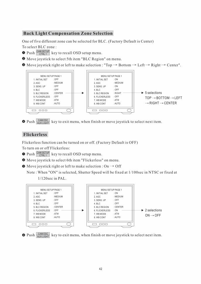
One of five different zone can be selected for BLC. (Factory Default is Center)
To select BLC zone :
Push key to recall OSD setup menu.
Move joystick to select 5th item "BLC Region" on menu.
Move joystick right or left to make selection : "Top Bottom Left Right Center".
Push key to exit menu, when finish or move joystick to select next item.
1CAM SETUP
CTRL 1
CAM ESCAUX LIGHT
Back Light Compensation Zone Selection
2
3
4
Flickerless function can be turned on or off. (Factory Default is OFF)
To turn on or off Flickerless:
Push key to recall OSD setup menu.
Move joystick to select 6th item "Flickerless" on menu.
Move joystick right or left to make selection : On Off
Note : When "ON" is selected, Shutter Speed will be fixed at 1/100sec in NTSC or fixed at
1/120sec in PAL.
Push key to exit menu, when finish or move joystick to select next item.
1CAM SETUP
CTRL 1
CAM ESCAUX LIGHT
Flickerless
2
3
4
MENU SETUP PAGE 1
1. INITIAL SET
2. AGC
3. SENS. UP
4. BLC
5. BLC REGION
6. FLICKERLESS
7. WB MODE
8. WB CONT
: OFF
: MEDIUM
: OFF
: OFF
: CENTER
: OFF
: ATW
: AUTO
MENU SETUP PAGE 1
1. INITIAL SET
2. AGC
3. SENS. UP
4. BLC
5. BLC REGION
6. FLICKERLESS
7. WB MODE
8. WB CONT
: ON
: MEDIUM
: ON
: OFF
: RIGHT
: OFF
: ATW
: AUTO
5 selections
TOP BOTTOM LEFT
RIGHT CENTER
MENU SETUP PAGE 1
1. INITIAL SET
2. AGC
3. SENS. UP
4. BLC
5. BLC REGION
6. FLICKERLESS
7. WB MODE
8. WB CONT
: OFF
: MEDIUM
: OFF
: OFF
: CENTER
: OFF
: ATW
: AUTO
MENU SETUP PAGE 1
1. INITIAL SET
2. AGC
3. SENS. UP
4. BLC
5. BLC REGION
6. FLICKERLESS
7. WB MODE
8. WB CONT
: ON
: MEDIUM
: OFF
: OFF
: CENTER
: ON
: ATW
: AUTO
2 selections
ON OFF
43
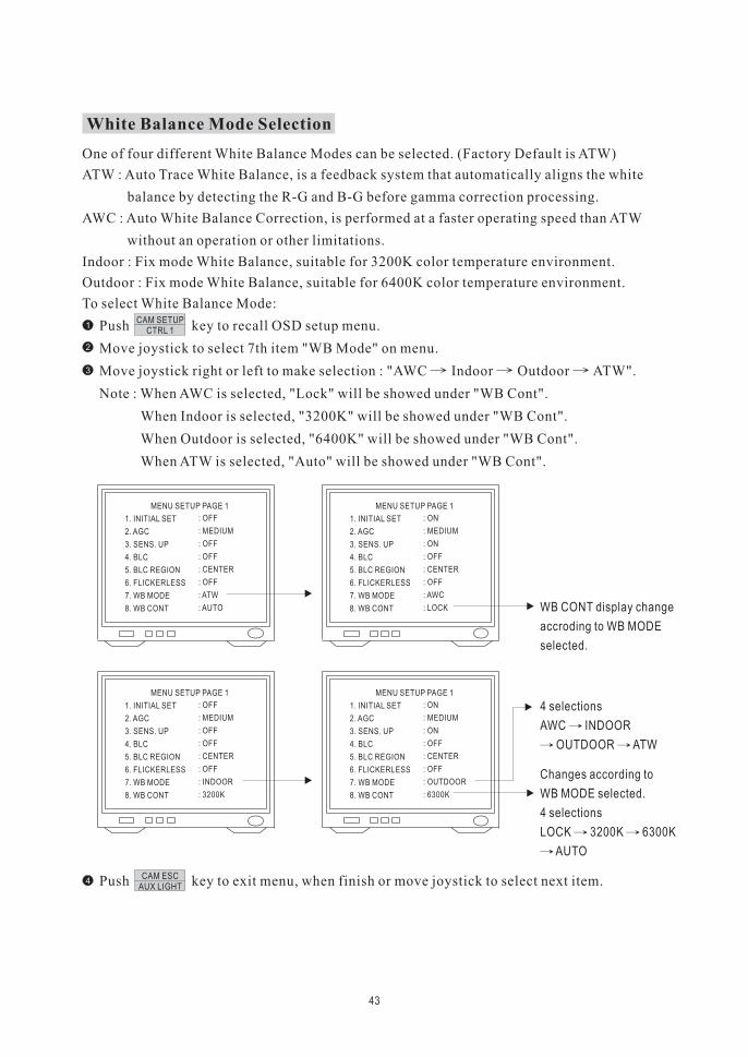
One of four different White Balance Modes can be selected. (Factory Default is ATW)
ATW : Auto Trace White Balance, is a feedback system that automatically aligns the white
balance by detecting the R-G and B-G before gamma correction processing.
AWC : Auto White Balance Correction, is performed at a faster operating speed than ATW
without an operation or other limitations.
Indoor : Fix mode White Balance, suitable for 3200K color temperature environment.
Outdoor : Fix mode White Balance, suitable for 6400K color temperature environment.
To select White Balance Mode:
Push key to recall OSD setup menu.
Move joystick to select 7th item "WB Mode" on menu.
Move joystick right or left to make selection : "AWC Indoor Outdoor ATW".
Note : When AWC is selected, "Lock" will be showed under "WB Cont".
When Indoor is selected, "3200K" will be showed under "WB Cont".
When Outdoor is selected, "6400K" will be showed under "WB Cont".
When ATW is selected, "Auto" will be showed under "WB Cont".
Push key to exit menu, when finish or move joystick to select next item.
1CAM SETUP
CTRL 1
CAM ESCAUX LIGHT
White Balance Mode Selection
2
3
4
MENU SETUP PAGE 1
1. INITIAL SET
2. AGC
3. SENS. UP
4. BLC
5. BLC REGION
6. FLICKERLESS
7. WB MODE
8. WB CONT
: OFF
: MEDIUM
: OFF
: OFF
: CENTER
: OFF
: ATW
: AUTO
MENU SETUP PAGE 1
1. INITIAL SET
2. AGC
3. SENS. UP
4. BLC
5. BLC REGION
6. FLICKERLESS
7. WB MODE
8. WB CONT
: ON
: MEDIUM
: ON
: OFF
: CENTER
: OFF
: AWC
: LOCK WB CONT display change
accroding to WB MODE
selected.
MENU SETUP PAGE 1
1. INITIAL SET
2. AGC
3. SENS. UP
4. BLC
5. BLC REGION
6. FLICKERLESS
7. WB MODE
8. WB CONT
: OFF
: MEDIUM
: OFF
: OFF
: CENTER
: OFF
: INDOOR
: 3200K
MENU SETUP PAGE 1
1. INITIAL SET
2. AGC
3. SENS. UP
4. BLC
5. BLC REGION
6. FLICKERLESS
7. WB MODE
8. WB CONT
: ON
: MEDIUM
: ON
: OFF
: CENTER
: OFF
: OUTDOOR
: 6300K
4 selections
AWC INDOOR
OUTDOOR ATW
Changes according to
WB MODE selected.
4 selections
LOCK 3200K 6300K
AUTO
44
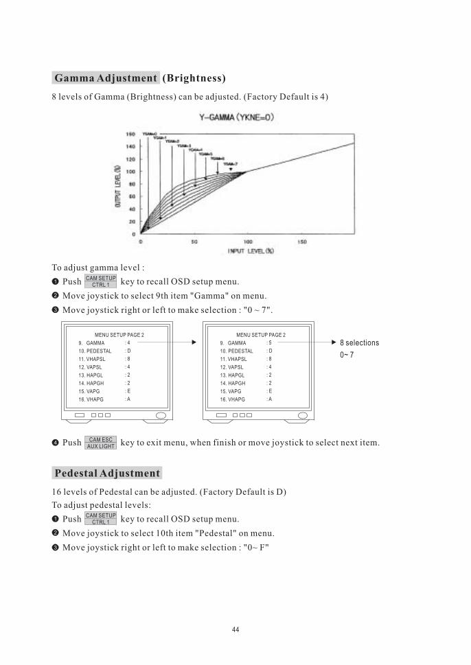
8 levels of Gamma (Brightness) can be adjusted. (Factory Default is 4)
To adjust gamma level :
Push key to recall OSD setup menu.
Move joystick to select 9th item "Gamma" on menu.
Move joystick right or left to make selection : "0 ~ 7".
Push key to exit menu, when finish or move joystick to select next item.
1CAM SETUP
CTRL 1
CAM ESCAUX LIGHT
Gamma Adjustment (Brightness)
2
3
4
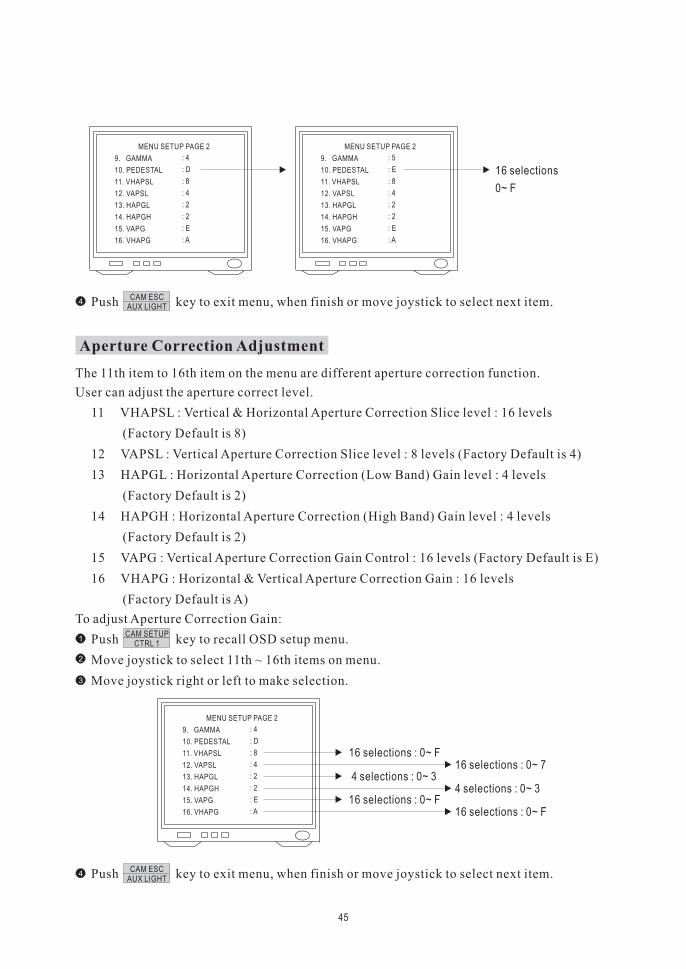
16 levels of Pedestal can be adjusted. (Factory Default is D)
To adjust pedestal levels:
Push key to recall OSD setup menu.
Move joystick to select 10th item "Pedestal" on menu.
Move joystick right or left to make selection : "0~ F"
1CAM SETUP
CTRL 1
Pedestal Adjustment
2
3
MENU SETUP PAGE 2
9. GAMMA
10. PEDESTAL
11. VHAPSL
12. VAPSL
13. HAPGL
14. HAPGH
15. VAPG
16. VHAPG
: 5
: D
: 8
: 4
: 2
: 2
: E
: A
MENU SETUP PAGE 2
9. GAMMA
10. PEDESTAL
11. VHAPSL
12. VAPSL
13. HAPGL
14. HAPGH
15. VAPG
16. VHAPG
: 4
: D
: 8
: 4
: 2
: 2
: E
: A
8 selections
0~ 7
45
MENU SETUP PAGE 2
9. GAMMA
10. PEDESTAL
11. VHAPSL
12. VAPSL
13. HAPGL
14. HAPGH
15. VAPG
16. VHAPG
: 5
: E
: 8
: 4
: 2
: 2
: E
: A
MENU SETUP PAGE 2
9. GAMMA
10. PEDESTAL
11. VHAPSL
12. VAPSL
13. HAPGL
14. HAPGH
15. VAPG
16. VHAPG
: 4
: D
: 8
: 4
: 2
: 2
: E
: A
16 selections
0~ F
Push key to exit menu, when finish or move joystick to select next item.CAM ESC
AUX LIGHT4
The 11th item to 16th item on the menu are different aperture correction function.
User can adjust the aperture correct level.
11 VHAPSL : Vertical & Horizontal Aperture Correction Slice level : 16 levels
(Factory Default is 8)
12 VAPSL : Vertical Aperture Correction Slice level : 8 levels (Factory Default is 4)
13 HAPGL : Horizontal Aperture Correction (Low Band) Gain level : 4 levels
(Factory Default is 2)
14 HAPGH : Horizontal Aperture Correction (High Band) Gain level : 4 levels
(Factory Default is 2)
15 VAPG : Vertical Aperture Correction Gain Control : 16 levels (Factory Default is E)
16 VHAPG : Horizontal & Vertical Aperture Correction Gain : 16 levels
(Factory Default is A)
To adjust Aperture Correction Gain:
Push key to recall OSD setup menu.
Move joystick to select 11th ~ 16th items on menu.
Move joystick right or left to make selection.
Push key to exit menu, when finish or move joystick to select next item.
1CAM SETUP
CTRL 1
CAM ESCAUX LIGHT
Aperture Correction Adjustment
2
3
4
MENU SETUP PAGE 2
9. GAMMA
10. PEDESTAL
11. VHAPSL
12. VAPSL
13. HAPGL
14. HAPGH
15. VAPG
16. VHAPG
: 4
: D
: 8
: 4
: 2
: 2
: E
: A
16 selections : 0~ F16 selections : 0~ 7
4 selections : 0~ 34 selections : 0~ 3
16 selections : 0~ F16 selections : 0~ F
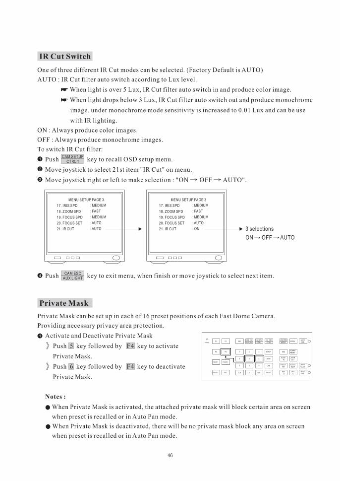
One of three different IR Cut modes can be selected. (Factory Default is AUTO)
AUTO : IR Cut filter auto switch according to Lux level.
When light is over 5 Lux, IR Cut filter auto switch in and produce color image.
When light drops below 3 Lux, IR Cut filter auto switch out and produce monochrome
image, under monochrome mode sensitivity is increased to 0.01 Lux and can be use
with IR lighting.
ON : Always produce color images.
OFF : Always produce monochrome images.
To switch IR Cut filter:
Push key to recall OSD setup menu.
Move joystick to select 21st item "IR Cut" on menu.
Move joystick right or left to make selection : "ON OFF AUTO".
Push key to exit menu, when finish or move joystick to select next item.
�
�
1CAM SETUP
CTRL 1
CAM ESCAUX LIGHT
IR Cut Switch
2
3
4
46
MENU SETUP PAGE 3
17. IRIS SPD
18. ZOOM SPD
19. FOCUS SPD
20. FOCUS SET
21. IR CUT
: MEDIUM
: FAST
: MEDIUM
: AUTO
: ON
MENU SETUP PAGE 3
17. IRIS SPD
18. ZOOM SPD
19. FOCUS SPD
20. FOCUS SET
21. IR CUT
: MEDIUM
: FAST
: MEDIUM
: AUTO
: AUTO 3 selections
ON OFF AUTO
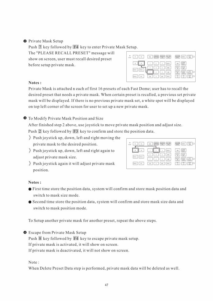
Private Mask can be set up in each of 16 preset positions of each Fast Dome Camera.
Providing necessary privacy area protection.
Activate and Deactivate Private Mask
Push 5 key followed by F4 key to activate
Private Mask.
Push 6 key followed by F4 key to deactivate
Private Mask.
When Private Mask is activated, the attached private mask will block certain area on screen
when preset is recalled or in Auto Pan mode.
When Private Mask is deactivated, there will be no private mask block any area on screen
when preset is recalled or in Auto Pan mode.
Notes :
1
Private Mask
POWERF1 F2
F4F3 1
PRESET1 PRESET2
FASTPRESET3
2 3 SETUP
MON654
CAM987
ENT0CLR PRESET
ESCAUX LIGHT CTRL2CTRL1
AUTOSPRAY
WIPER
SEQ
ZOOMIN
FARFOUCS
IRISO
NEAR
OUT
PAN
RESETALARM
ZOOM
FOUCS
IRISC
AUTO
AUTO
FOUCS
IRIS
CAM ESC 180 REVCAM SETUP LENS SPEED
Private Mask Setup
Push 7 key followed by F4 key to enter Private Mask Setup.
The "PLEASE RECALL PRESET" message will
show on screen, user must recall desired preset
before setup private mask.
Private Mask is attached n each of first 16 presets of each Fast Dome; user has to recall the
desired preset that needs a private mask. When certain preset is recalled, a previous set private
mask will be displayed. If there is no previous private mask set, a white spot will be displayed
on top left corner of the screen for user to set up a new private mask.
Notes :
2
47
POWERF1 F2
F4F3 1
PRESET1 PRESET2
FASTPRESET3
2 3 SETUP
MON654
CAM987
ENT0CLR PRESET
ESCAUX LIGHT CTRL2CTRL1
AUTOSPRAY
WIPER
SEQ
ZOOMIN
FARFOUCS
IRISO
NEAR
OUT
PAN
RESETALARM
ZOOM
FOUCS
IRISC
AUTO
AUTO
FOUCS
IRIS
CAM ESC 180 REVCAM SETUP LENS SPEED
3
4
To Modify Private Mask Position and Size
After finished step 2 above, use joystick to move private mask position and adjust size.
Push joystick up, down, left and right moving the
private mask to the desired position.
Push joystick up, down, left and right again to
adjust private mask size.
Push joystick again it will adjust private mask
position.
First time store the position data, system will confirm and store mask position data and
switch to mask size mode.
Second time store the position data, system will confirm and store mask size data and
switch to mask position mode.
To Setup another private mask for another preset, repeat the above steps.
Escape from Private Mask Setup
Push 8 key followed by F4 key to escape private mask setup.
If private mask is activated, it will show on screen.
If private mask is deactivated, it will not show on screen.
Note :
When Delete Preset Data step is performed, private mask data will be deleted as well.
Notes :
Push 2 key followed by F3 key to confirm and store the position data.
POWERF1 F2
F4F3 1
PRESET1 PRESET2
FASTPRESET3
2 3 SETUP
MON654
CAM987
ENT0CLR PRESET
ESCAUX LIGHT CTRL2CTRL1
AUTOSPRAY
WIPER
SEQ
ZOOMIN
FARFOUCS
IRISO
NEAR
OUT
PAN
RESETALARM
ZOOM
FOUCS
IRISC
AUTO
AUTO
FOUCS
IRIS
CAM ESC 180 REVCAM SETUP LENS SPEED
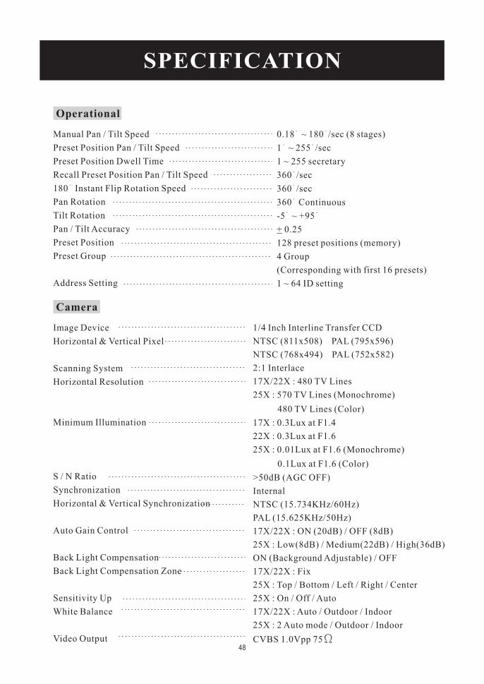
SPECIFICATION
Operational
Manual Pan / Tilt Speed
Preset Position Pan / Tilt Speed
Preset Position Dwell Time
Recall Preset Position Pan / Tilt Speed
180 Instant Flip Rotation Speed
Pan Rotation
Tilt Rotation
Pan / Tilt Accuracy
Preset Position
Preset Group
Address Setting
0.18 ~ 180 /sec (8 stages)
1 ~ 255 /sec
1 ~ 255 secretary
360 /sec
360 /sec
360 Continuous
-5 ~ +95
0.25
128 preset positions (memory)
4 Group
(Corresponding with first 16 presets)
1 ~ 64 ID setting
+
Camera
Image Device
Horizontal & Vertical Pixel
Scanning System
Horizontal Resolution
Minimum Illumination
S / N Ratio
Synchronization
Horizontal & Vertical Synchronization
Auto Gain Control
Back Light Compensation
Back Light Compensation Zone
Sensitivity Up
White Balance
Video Output
1/4 Inch Interline Transfer CCD
NTSC (811x508) PAL (795x596)
NTSC (768x494) PAL (752x582)
2:1 Interlace
17X/22X : 480 TV Lines
25X : 570 TV Lines (Monochrome)
480 TV Lines (Color)
17X : 0.3Lux at F1.4
22X : 0.3Lux at F1.6
25X : 0.01Lux at F1.6 (Monochrome)
0.1Lux at F1.6 (Color)
>50dB (AGC OFF)
Internal
NTSC (15.734KHz/60Hz)
PAL (15.625KHz/50Hz)
17X/22X : ON (20dB) / OFF (8dB)
25X : Low(8dB) / Medium(22dB) / High(36dB)
ON (Background Adjustable) / OFF
17X/22X : Fix
25X : Top / Bottom / Left / Right / Center
25X : On / Off / Auto
17X/22X : Auto / Outdoor / Indoor
25X : 2 Auto mode / Outdoor / Indoor
CVBS 1.0Vpp 7548
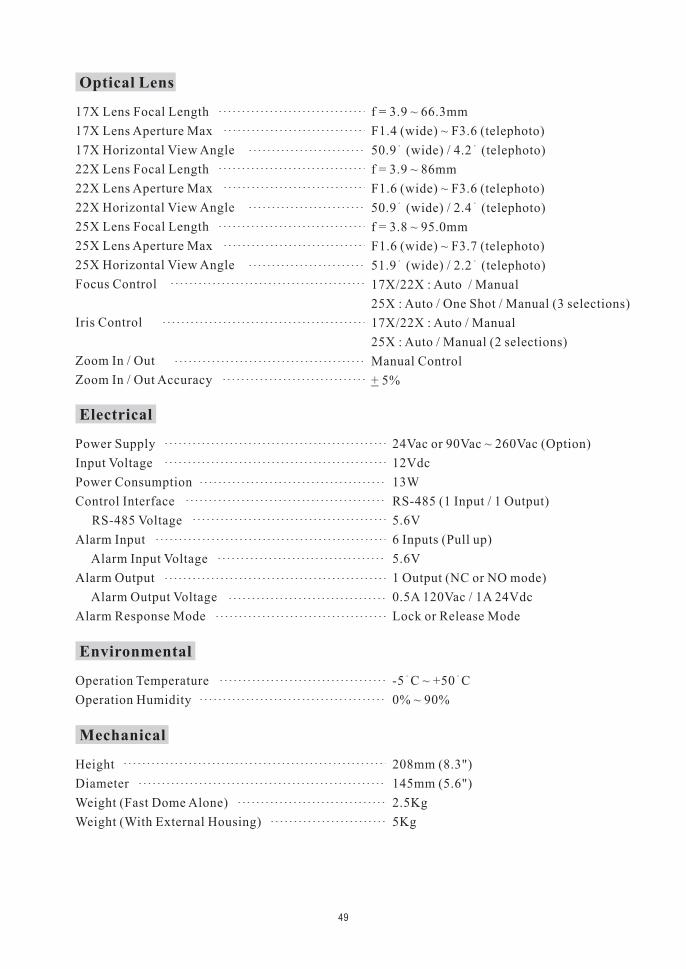
Optical Lens
17X Lens Focal Length
17X Lens Aperture Max
17X Horizontal View Angle
22X Lens Focal Length
22X Lens Aperture Max
22X Horizontal View Angle
25X Lens Focal Length
25X Lens Aperture Max
25X Horizontal View Angle
Focus Control
Iris Control
Zoom In / Out
Zoom In / Out Accuracy
f = 3.9 ~ 66.3mm
F1.4 (wide) ~ F3.6 (telephoto)
50.9 (wide) / 4.2 (telephoto)
f = 3.9 ~ 86mm
F1.6 (wide) ~ F3.6 (telephoto)
50.9 (wide) / 2.4 (telephoto)
17X/22X : Auto / Manual
25X : Auto / One Shot / Manual (3 selections)
17X/22X : Auto / Manual
25X : Auto / Manual (2 selections)
Manual Control
5%+
f = 3.8 ~ 95.0mm
F1.6 (wide) ~ F3.7 (telephoto)
51.9 (wide) / 2.2 (telephoto)
Electrical
Power Supply
Input Voltage
Power Consumption
Control Interface
RS-485 Voltage
Alarm Input
Alarm Input Voltage
Alarm Output
Alarm Output Voltage
Alarm Response Mode
24Vac or 90Vac ~ 260Vac (Option)
12Vdc
13W
RS-485 (1 Input / 1 Output)
5.6V
6 Inputs (Pull up)
5.6V
1 Output (NC or NO mode)
0.5A 120Vac / 1A 24Vdc
Lock or Release Mode
Environmental
Operation Temperature
Operation Humidity
-5 C ~ +50 C
0% ~ 90%
Mechanical
Height
Diameter
Weight (Fast Dome Alone)
Weight (With External Housing)
208mm (8.3")
145mm (5.6")
2.5Kg
5Kg
49
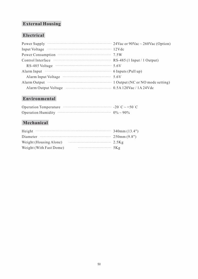
External Housing
Electrical
Power Supply
Input Voltage
Power Consumption
Control Interface
RS-485 Voltage
Alarm Input
Alarm Input Voltage
Alarm Output
Alarm Output Voltage
24Vac or 90Vac ~ 260Vac (Option)
12Vdc
7.5W
RS-485 (1 Input / 1 Output)
5.6V
6 Inputs (Pull up)
5.6V
1 Output (NC or NO mode setting)
0.5A 120Vac / 1A 24Vdc
Environmental
Operation Temperature
Operation Humidity
-20 C ~ +50 C
0% ~ 90%
Mechanical
Height
Diameter
Weight (Housing Alone)
Weight (With Fast Dome)
340mm (13.4")
250mm (9.8")
2.5Kg
5Kg
50
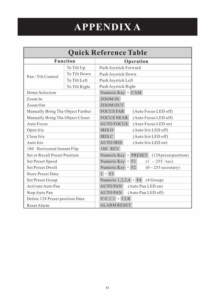
Function Operation
APPENDIX A
Quick Reference Table
Pan / Tilt Control
To Tilt Up
Dome Selection
To Tilt Down
To Tilt Left
To Tilt Right
Zoom In
Zoom Out
Manually Bring The Object Farther
Manually Bring The Object Closer
Auto Focus
Open Iris
Close Iris
Auto Iris
180 Horizontal Instant Flip
Set or Recall Preset Position
Set Preset Speed
Set Preset Dwell
Store Preset Data
Set Preset Group
Activate Auto Pan
Stop Auto Pan
Delete 128 Preset position Data
Reset Alarm
Numeric Key + CAM
ZOOM IN
ZOOM OUT
FOCUS FAR
FOCUS NEAR
AUTO FOCUS
IRIS O
IRIS C
AUTO IRIS
180 REV
Numeric Key + PRESET
Numeric Key + F1
Numeric Key + F2
1 + F3
Numeric 1,2,3,4 + F4
AUTO PAN
AUTO PAN
9 0 1 1 + CLR
ALARM RESET
Push Joystick Forward
Push Joystick Down
Push Joystick Left
Push Joystick Right
(Auto Focus LED off)
(Auto Focus LED off)
(Auto Focus LED on)
(Auto Iris LED off)
(Auto Iris LED off)
(Auto Iris LED on)
(128presetposition)
(1 ~ 255 /sec)
(0 ~ 255 secretary)
(4 Group)
(Auto Pan LED on)
(Auto Pan LED off)
51
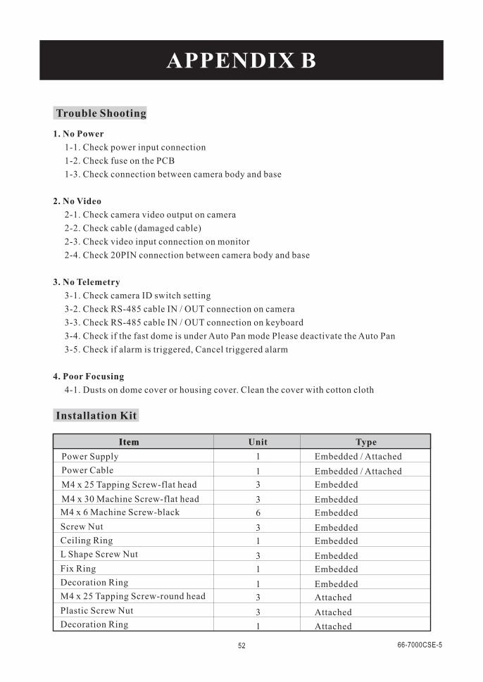
APPENDIX B
Trouble Shooting
1. No Power
2. No Video
3. No Telemetry
4. Poor Focusing
1-1. Check power input connection
1-2. Check fuse on the PCB
1-3. Check connection between camera body and base
2-1. Check camera video output on camera
2-2. Check cable (damaged cable)
2-3. Check video input connection on monitor
2-4. Check 20PIN connection between camera body and base
3-1. Check camera ID switch setting
3-2. Check RS-485 cable IN / OUT connection on camera
3-3. Check RS-485 cable IN / OUT connection on keyboard
3-4. Check if the fast dome is under Auto Pan mode Please deactivate the Auto Pan
3-5. Check if alarm is triggered, Cancel triggered alarm
4-1. Dusts on dome cover or housing cover. Clean the cover with cotton cloth
Power Supply
M4 x 6 Machine Screw-black
Power Cable
M4 x 25 Tapping Screw-flat head
M4 x 30 Machine Screw-flat head
Screw Nut
Ceiling Ring
L Shape Screw Nut
Fix Ring
Decoration Ring
M4 x 25 Tapping Screw-round head
Plastic Screw Nut
Decoration Ring
Installation Kit
ItemItem Unit Type
1
1
3
3
6
3
1
3
1
1
3
3
1
Embedded / Attached
Embedded / Attached
Embedded
Embedded
Embedded
Embedded
Embedded
Embedded
Embedded
Embedded
Attached
Attached
Attached
52 66-7000CSE-5

FAST DOME CAMERAPIH-7000/7600/7625 Series
INSTRUCTION MANUAL
MERIT LILIN ENT. CO., LTDhttp://www.meritlilin.com 66-7000CSE