Embed Size (px)
Citation preview
JOURNAL OF STRVCTURAL C ~ O L , VOL. 6 N. 1 JUNE 1999
Piezoelectric Plates with Changing Thickness
147
V. Nicotra and P. Podio-Guidugli Dipartimento di Ingegnericr Civile Universita di Roma “Tor Vergata” 00133 Roma - Italy
Abstract. A linear theory of electroelastic plates capable of thickness changes is presented. It is shown that, for transversely isotropic plates, the general boundary-value problem decouples into a membrane problem and a flexure problem; in each subproblem, piezoelectric and electrostrictive effects are in order, with peculiar forms. An example is studied, where thickness changes in membrane regime are induced either by mechanical loads or by electric loads.
Key words: Plates, piezoelectric effect, electroelastic effect, electroelasticity.
1 Introduction
We deduce from three-dimensional electroelasticity a fairly general linear theory of electroelastic plates (Bisegna & Maceri, 1996; Ikeda, 1990; Maugin, 1988; Tier- sten, 1969). The principles of our deduction, which is exact, are the same as in (DiCarlo et al., 1998), where however the context was purely mechanical. Our pre- sentation, although reasonably self-contained, relies on the detailed discussions in a forthcoming book (Podio-Guidugii, 1998) and in Nicotra’s doctoral thesis (Nico- tra, 1998). As in (DeSimone & Podio-Guidugli, 1995) and (DiCarlo et al., 1998), the plate theory we obtain is able to account for thickness changes. To illustrate this feature, that traditional plate theories do not possess, we consider a simple example where thickness changes are due to a combination of electromechanical loads.
2 Boundary-Value Problems for Electroelastic Plates
This section is based on the presentation of mechanical plate theories given in (Podio-Guidugli, 1998) and generalized in (Nicotra, 1998) so as to cover electroe- lastic plates.
2.1 THREE-DIMENSIONAL BACKGROUND
We begin by describing a platelike region in 3-D space. Let (0; c1, cq, z} be an orthonormal Cartesian frame, and let P be an open and bounded region in the z1 - 52 plane, with the boundary curve 8P having a.e. well-defined tangent T and outer normal u. A platelike region of thickness 2 6 is a right cylinder C ( E ) = P x ] - c , + E [ , such that 2~ << diarn(P). For z and p the typical points of, respectively, P and C ( E ) we have that
p = J: + (2, Iz: = z,c,. (1)
148 V. NICOTRA A N D P. PODIO-GUIDUGLI
The boundary aC(c) of C ( E ) consists of the lateral mantle dP x ( - - E , + E ] and the end faces P* = P x {Ax}. With a view toward a formulation of boundary- value problems for plates with linearly electroelastic response, we split dP into two parts, aq,P and &P, pairwise complementary and disjoint; with this, we construct a corresponding splitting of ~ C ( E ) :
a+c(c) = a$P x [ -e,+c], a&(€) = (ad? x + E l ) u P- u P+. (2) As a consequence of the above definitions, the boundary parts a&(€) and &C(C) turn out to be pairwise complementary and disjoint:
a+c(e) u a&(€) = ac(E), a,#$(€) u adc(E) = 8. (3) Wc arc now in a position to specify the electric boundary data on the platelike body C ( E ) , namely, - an electric potential 4, over a&(€); - a surface charge w, over &C(c).
The mechanical boundary data we consider are: - a contact load s,' (s; ) over P+ (P-); - a triplet (u,,s,, Po) of fields over dP x [ - E , + E ] , consisting of a displacement
uo(x, 0, a contact load so(z,f), and an orthogonal projection Po(z), such that the map z +-+ Po(.) is piecewise constant and takes values in the set (0, I, u(x) @ v(x), I - u ( x ) @ ~ ( 2 ) ) ) and that
(I - Po)uo = 0) POSO = 0 (4)
(here I denotes the identity tensor, @ the standard dyadic product. of vectorial objects). Moreover, we consider as assigned in C(E) a distance load b, and a volume charge yo.
As basic unknowns we choose the displacement u and the electric potential 4, a vector and a scalar field over C ( E ) . The strain tensor E and the electric-field vector e are linked to, respectively, the displacement and the electric potential by the compatibility relations
E = sym[Vu], e = -V4 (5) (here sym(.] evaluates the symmetric part of a tensor). Work-conjugate to the kinematic variables (E, e ) are the dynamic variables (S, d), that is, respectively, the (symmetric) stress tensor and the electric-displacement vector. The basic balance principle is the virtual work principle, that is, the requirement that
so . + L,,, + L,,,., WrJllf = 0 (6) .I,,,, (S . VV - d . O$) - b, v - L,,, J,,4 for all test fields (v,$) such that P,v vanishes over c?P x [ - E , + E ] and $1 vanishes over 8q,C(e).
PIEZOELECTRIC PLATES WITH CHANGING THICKNESS 149
2 .2 An assumption crucial to our deduction of a system of 2-D balance equations for electroelastic plates is that we restrict attention to three-dimensional unknown fields u(5, C), 4 ( ~ , () of a form Linear in the transverse coordinate C and parametri- zed by fields uo(x), . . . , #1(z) defined over P:
REPRESENTATIONS FOR DISPLACEMENT AND ELECTRIC POTENTIAL
with uo(z,C) = a(.) + w(z)z, a(z) 5 z = 0,
(8) ~1 (z, C ) = b(z) + U(Z)Z, b(z) . z = 0.
Here a(.) is the in-plane displacement and 4 z ) z the transverse displacement of a point x E P, while b(x) measures the rotation, and u(z) the strain, of a transverse fiber through x. Note that we do not require that b + Vw = 0 , the kinematical restriction that yields plate theories of Kirchhoff-Love type. We shall refer to u, a kinematical parameter which is absent in all classical theories of plates, be they piezoelectric or not, as to the thickness strain. In principle, the fields w and b account for the flexural behavior of the resulting plate, whereas the fields a and u account for the membrane behavior; we shall return to this feature of our approach to plates by the end of Subsection 2.4.
It is important to realize that any a przori restriction on the form of the solu- tion reduces the generality of the admissible assignments of boundary data. In particular, (7) and (8) imply that the pointwise prescriptions of the displacement u, over 8P x [-c, +E] and the electric potential 4o over B&(E) be replaced by the following two-dimensional boundary conditions:
in aP, (9)
2 3 -1= Po(a + m) = (2e)-’ii0, P,(b + uz) = (y ) Q,
with
with
150 V. NICOTRA AND P. PODIO-GUIDUGLI
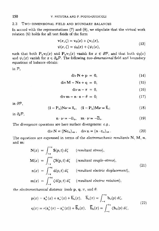
2.3 TWO-DIMENSIONAL FIELD A N D BOUNDARY BALANCES
In accord with the representations (7) and (8), we stipulate that the virtual work relation (6) holds for all test fields of the form
such that both P,vo(z) and Povl(x) vanish for x E @P, and that both &(z) and $ J ~ ( S ) vanish for 2 E a,P. The following two-dimensional field and boundary equations of balance obtain:
in P,
d i v N f p = 0, (14)
d i v M - N z + q = 0, (15)
t 16)
d i v m - n . z - B = 0; (17)
divn - K = 0,
The divergence operators are here surface divergences: e.g.,
divN = (Nca) , , , , div n = (n . c ~ ) , ~ . (20)
The equations are expressed in terms of the electromechanic resultants N , MI n, and m:
N(z) = /" S ( p , t ) dC
M(X) = I-: < s ( p , t) tic (resultant couple-stress),
(resultant stress), --e
(21) n(x) = L: d(p, t ) d<
m(x) = /-: Cd(p, t ) dc
(resultant electric displacement) ,
(resultant electric rotation);
the electromechanical distance-loads p, q, T , and 8:
PIEZOELECTRIC PLATES WITH CHANGING THICKNESS 15 1
and the electromechanical contact-loads So, $, Do, and so:
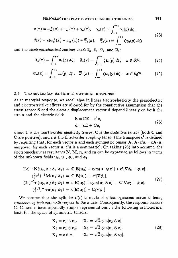
2.4 TRANSVERSELY ISOTROPIC MATERIAL RESPONSE
As to material response, we recall that in linear electroelasticity the piezoelectric and electrostrictive effects are allowed for by the constitutive assumption that the stress tensor S and the electric displacement vector d depend linearly on both the strain and the electric field:
S = CE - c'e, d = cE + Ce,
where C is the fourth-order elasticity tensor, C is the dielectric tensor (both C and C are positive), and c is the third-order coupling tensor (the transpose ct is defined by requiring that, for each vector a and each symmetric tensor A, A .eta = cA ma; moreover, for each vector a, cta is a symmetric). On taking (26) into account, the electromechanical resultants N, M, n, and m can be expressed as follows in terms of the unknown fields uo, u1, $0, and @I:
(26)
(W-"(uo, u1; 40,41) = Who) + sym(u1 c3 41 + Ct[V4O + 014
(2~)-'n(uo, w; 4 0 , h ) = c[E(uo) + sym(u1 z)] - C [ ~ @ O + 414, ( $ ~ ~ ) - l m ( ~ ; 41) = c[E(w)] - ~ [ v d l ]
(27) ( $ W M ( W ; $1) = @ [ E ( U ~ ) ] + ct[vhI,
We assume that the cylinder C(E) is made of a homogeneous material being transversely isotropic with respect to the z axis. Consequently, the response tensors @, C . and c have especially simple representations in the following orthonormal basis for the space of symmetric tensors:
152 V . NICOTRA AND P. PODIO-GUIDUGLI
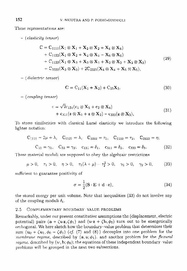
These representations are:
- (elasticity tensor)
- (daelectrw tensor)
- (coupling tensor)
(31) c = &@131(C1 @ x5 + c2 @ X,) f 6311(2 @'XI + 2 8 x2) + c333(z @ x 3 ) ~
To stress similarities with classical Lam6 elasticity we introduce the following lighter notation:
These material moduli are supposed to obey the algebraic restrictions
sufficient t o guarantee positivity of
(34) 1 2 CT = - ( S . E + d . e ) ,
the stored energy per unit volume. Note that inequalities (33) do not involve any of the coupling moduli 6,.
2.5 COMPLEMENTARY BOUNDARY-VALUE PROBLEMS
Remarkably, under our present constitutive assumptions the (displacement, electric potential) pairs (a + Cu z, C $ q ) and ( w z + cb, 40) turn out t o be energetically orthogonal. We here sketch how the boundary-value problem that determines their sum ( u g + ( u ~ , & I + C&) ( c j . (7) and (8) ) decouples into one problem for the membrane regime, described by (a, u ; # I ) , and another problem for the fEexi~ral ~ e ~ ~ m e , described by (w, b; 40); the equations of these independent boundary-valuc prohiemu will bc grouped in the next two subsections.
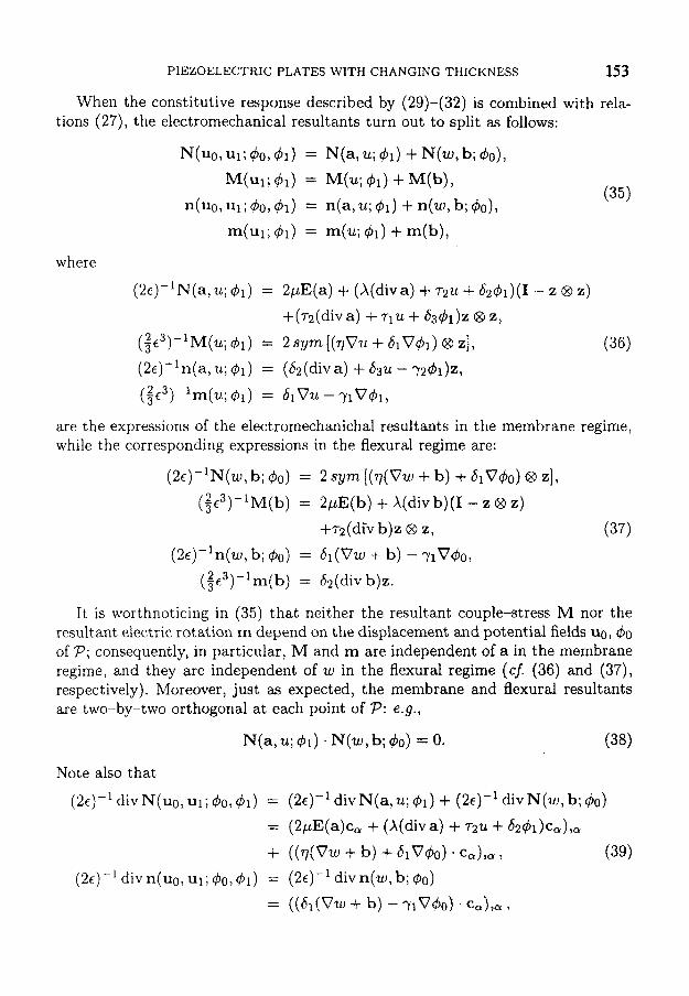
PIEZOELECTRIC PLATES WITH CHANGING THICKNESS 153
When the constitutive response described by (29)-(32) is combined with rela- tions (27), the electromechanical resultants turn out to split as follows:
where
are the expressions of the electromechanichal resultants in the membrane regime, while the corresponding expressions in the flexural regime are:
(2e)-'N(w, b; 40) = 2 sym ( ( ~ ( V W + b) + 61040) @ z],
(it3)-'M(b) = 2pE(b) + X(div b)(I - z @ z)
+72(div b ) ~ 8 Z, (37) (24- 'n (w, b; $0) = &(VW + b) - YlVdO,
( i e3 ) - 'm(b ) = bn(div b)z.
It is worthnoticing in (35) that neither the resultant couple-stress M nor the resultant electric rotation m depend on the displacement and potential fields uo, 40 of P; consequently, in particular, M and m are independent of a in the membrane regime, and they are independent of w in the flexural regime (cf. (36) and (37), respectively). Moreover, just as expected, the membrane and flexural resultants are two-by-two orthogonal at each point of P: e.g.,
N(a, u; 41) . N(w, b; 40) = 0. (38)
154 V. NICOTRA AND P. PODIO-GUIDUGLI
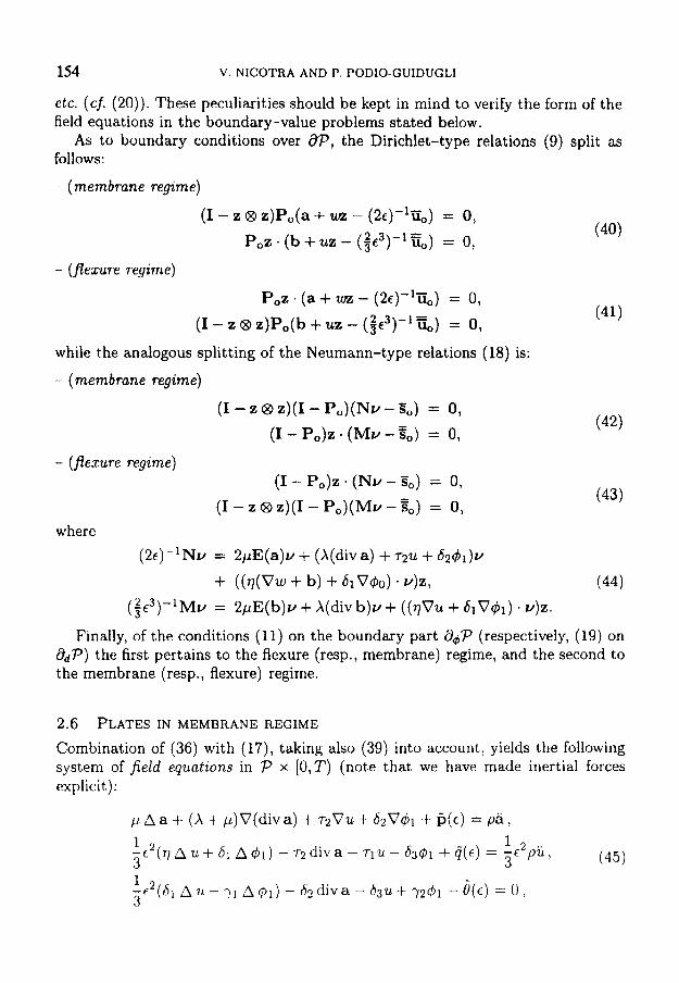
etc. ( c j . (20) ) . These peculiarities should be kept in mind to verify the form of the field equations in the boundary-value problems stated below.
As to boundary conditions over 8P, the Dirichlet-type relations (9) split as follows:
- (membrane regime)
(I - z B z)Po(a + m - (2c)-liiO) = 0, P,z * (b + uz - (3c3)-'EO) = 0,
- (flexure regime)
P,z. (a + un - ( 2 ~ ) - l ~ i ~ ) = 0,
(I - z 8 z)P,(b + uz - (3e3)-' Go) = 0,
while the analogous splitting of the Neumann-type relations (18) is:
- (membrane regime)
(I - z @ z)(I - P,)(Nv - So) = 0, (I - P,)z * (Mv -go) = 0, (42)
- (flexure regime) (I - P,)z * (NY - So) 0,
(I - z 8 z)(I - PO)(MV - Eo) = 0, (43)
where (2c)-lNv = 2pE(a)v + (X(diva) + 72u + 6 2 4 1 ) ~
+ ( ( O w + b) + 61V40) .v)z, (44) ( 3c3)-'Mv = 2pE(b)v + X(div b)v + ( ( ~ V U + 61V&) . v)z .
Finally, of the conditions (11) on the boundary part 8dP (respectively, (19) on &P) the first pertains to the flexure (resp., membrane) regime, and the second to the membrane (resp., flexure) regime.
2.6 PLATES IN MEMBRANE REGIME
Combination of (36) with (17), taking also (39) into account, yields the following system of f ield equations in P x [O,T) (note that we have made inertial forces explicit ) :
p A a i- (A + p)V(diva) + r2Vu + 62041 + P(E) = pa,
1 1 2 .. - t 2 ~ 7 1 n u . + 6 1 A ~ 1 ) - r 2 d i v a - 7 1 u . - d 3 ~ l + q ( ~ ) = 3 --E 3 p u , (45)
PIEZOELECTRIC PLATES WITH CHANGING THICKNESS 155
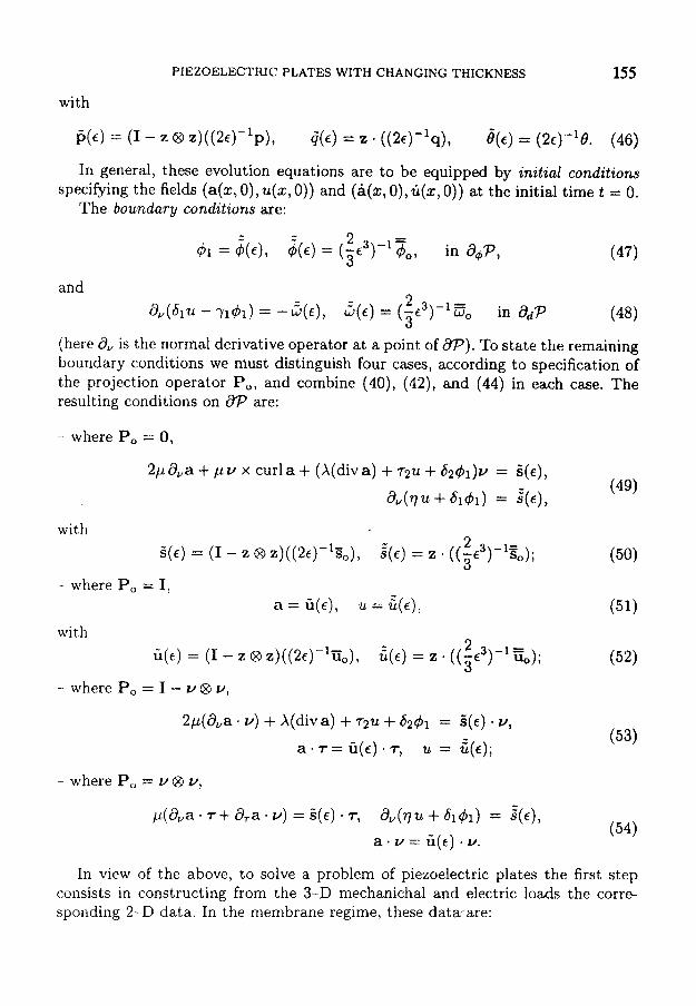
with
p(6) = (I - z @ z ) ( (~E) - ’P) , G ( E ) = z . ( ( 2 ~ ) - l q ) , &) = ( 2 ~ ) - l e . (46)
In general, these evolution equations are to be equipped by initial conditions specibing the fields (a(z, 0), u(z, 0)) and (a(%, 0), G(z, 0)) at the initial time t = 0.
The boundary conditions are:
and
(48) ~,(s,u. - 7141) = - G ( E ) , 5(c) = ( 3 6 2 3 ) - I = w, in ad^ (here 8, is the normal derivative operator at a point of 673). To state the remaining boundary conditions we must distinguish four cases, according to specification of the projection operator Po, and combine (40), (42), and (44) in each case. The resulting conditions on 8P are:
- where Po = 0,
with 2 3 -1= . Z ( E ) = (I - 2 8 Z)((2E)-130), :(€) = z ’ ((,€ ) so),
- where Po = I,
with a = u(E), u = G ( E ) ,
2 3 - I = G(E) = (I - 2 8 Z)((2€)-’TJo), t (€) = z ((-€ ) uo); 3
-- where Po = I - u @ u,
- where Po = u @ u,
In view of the above, to solve a problem of piezoelectric plates the first step consists in constructing from the 3-D mechanichal and electric loads the corre- sponding 2-D data. In the membrane regime, these data are:
156 V. NICOTRA A N D P. PODIO-G'UIDUGLI
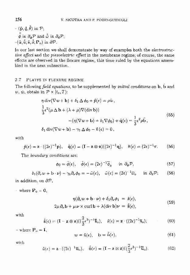
- 4 in a,P and 5 in &P; -(ii, t; 6 , S ; Po) in 8 ~ . In our last section we shall demonstrate by way of examples both the electrostric- Live eflect and the piezoelectric effect in the membrane regime; of course, the same effects are observed in the flexure regime, this time ruled by the equations assem- bled in the next subsection.
2.7 PLATES IN FLEXURE REGIME
The following field equations, to be supplemented by initial conditions on b, b and w , w, obtain in P x [ t , ,T ) :
q d i v ( V w + b ) + 6 1 A # o + f j ( ~ ) = p i i ~ , 1 - e 2 ( p A b + ( A + ,u)V(div b)) 3
(55) 1 - ( ~ ( V W + b) + 61V&) + q ( ~ ) 3 ;5c2pb,
61 div(Vw+ b) - y1 Ado - # ( E ) = 0,
with
I s ( € ) = 1 : . ((2c)-'p), G(E) = (I - z @ z ) ( ( ~ E ) - ' s ) , + ( E ) = ( 2 ~ ) - l r . (56)
The boundary conditions are:
where Po = 0,
V(&W + b . V) + 61&$1 = a(€), (59)
2 p & b + p v x curlb+X(divb)v = E ( E ) ,
(60) 2 3
with i ( c ) = (I - 2 @ z)((-€3)-130)1 S ( E ) = 2 . ( ( 2 q 1 S o ) ;
- where Po = I , w = i i ( ~ ) , b = A ( F ) ,
(62) 2 3 -1=
with G ( € ) = 2 . ((2€)-%<,), $€) = ( I - 2 QD Z)((,€ ) u"):
PIEZOELECTRTC PLATES WITH CHANGING THICKNESS 157
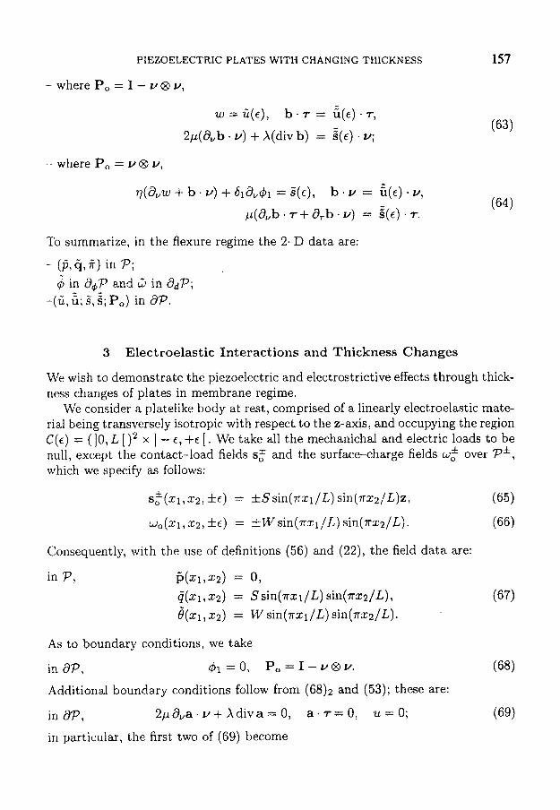
- w h e r e P , = I - u @ v ,
w = i i ( ~ ) , b . 7 = 6 ( ~ ) . 7,
2,u(d,b. v) + X(div b) = a(€) . u; -
- where Po = u@ Y,
To summarize, in the flexure regime the 2-D data are:
- ($,q,jT) in P; - 4 in a,P and LJ in ddP; -(G, t; S , 2; P,) in 8 ~ .
I
3 Electroelastic Interactions and Thickness Changes
We wish to demonstrate the piezoelectric and electrostrictive effects through thick- ness changes of plates in membrane regime.
We consider a platelike body at rest, comprised of a linearly electroelastic mate- rial being transversely isotropic with respect. to the z-axis, and occupying the region C(c ) = (10, L [ )2 x ] - E , +E [ . We take all the mechanichal and electric loads to be null, except the contact-load fields s$ and the surface-charge fields w,f over P*, which we specify as follows:
s : ( ~ , T c ~ , * e ) = *Ssin(nzl/L) sin(.rrzz/~)z,
wo(z1,z2, 5 6 ) = fWsin(.rrzl/L) sin(.rrzn/L).
Consequently, with the use of definitions (56) and (22), the field data are:
in P , i+1,22) = 0, 0(xl,z2) = Ssin(ml /L) sin(m:a/L), 8 ( q , z2) = w sin(.rrxl/L) sin(nzz/L).
As to boundary conditions, we take
in aP, & = O , P , = I - v @ V .
Additional boundary conditions follow from ( 6 8 ) ~ and (53); these are:
in d P , 2,ua”a. Y + Xdiva = 0, a . r = 0, u = 0;
in particular, the first two of (69) become
158 V. NICOTRA AND P. PODIO-GUIDUGLI
for 2 1 E {O,L}, a 2 , 2 = 0, a1 = 0, (70) for x2 E (0, L}, a ~ , ~ = 0, a2 = 0. (71)
We look for a solution (a, u; 41) of (45) being compatible with these data and having the form:
a l ( z 1 , ~ ) = A1 cos(nq/L) sin(nx2/l), a2(21 ,q) = A2 sin(nzl/L) cos(mz/L),
u ( q , q ) = Usin(lrsl/L) sin(nzz/L), $1 (XI , z2) = Fl sin(?rq/L) sin(mz/L)
(note that the representation (72) is automatically consistent with both boundary conditions (68)1 and (69)3). We then arrive to an algebraic system whose solution (Al,A2,U,Fl) depends linearly on the load amplitudes (S ,W) ; in particular, the piezoelectric effect obtains for (S,O), the electrostrictive effect for (0, W ) .
(72)
Precisely, the piezoelectric solution has the form:
where
Likewise, the electrostrictive solution has the form:
where
A(t) = (2~)-'[9(7263 - 7182) + 6n2(7261 - 7 6 2 ) ( ~ / L ) ~ ] ,
B(6) = 9[(2p + A)& - 72621 + 6n2(2p + A ) ~ ~ ( E / L ) ~ , c(t) = 9 [ ( 2 p -k x)T1 - 7221 + 6r2(2p 1- x)7](E/L)2.
Our nunierical results are for a plate in lead tzta7~ate-zi~conate (these piezoelec- tric ceramics are generally formidated as PbZr(l-,)Ti, 0 3 with z close to 0.5).
PIEZOELECTRIC PLATES WITH CHANGING THICKNESS 159
P [GPaI
X [GPa]
77 I G W
71 [GPaI
7 2 [GPaI
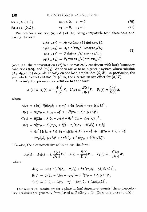
Table 1 displays the material’s constitutive moduli: mechanical (1, A, q, 71, ~ 2 ) ,
piezoelectric (61, 52, 83) , and dielectric (71, 72); Table 2 gives the solution ( A l l Az , U , Fl ) in the piezoelectric and electrostrictive cases (first and second column, resp.), for a plate of side length L = 0.1 m and thickness 2c = 0.05 m.
24.95 51 [C/m2] 11.80
82.30 52 [C/m2] -4.30
29.50 53 [C/m21 16.70
120.00 71 [nF/mI 17.43
83.70 7 2 [nF/ml 16.37
Lead titanate-zirconate P1-88
Amplitudes a 9.176 x 10⁻⁵S
9.176 x 10⁻⁵S
9.613 x S 9.855 x 10⁻³S
e 1.159 x lW4 W
1.159 x W
9.855 x W
-3.213 x
TABLE 2. Amplitudes (S in GPa, W in C/m2).
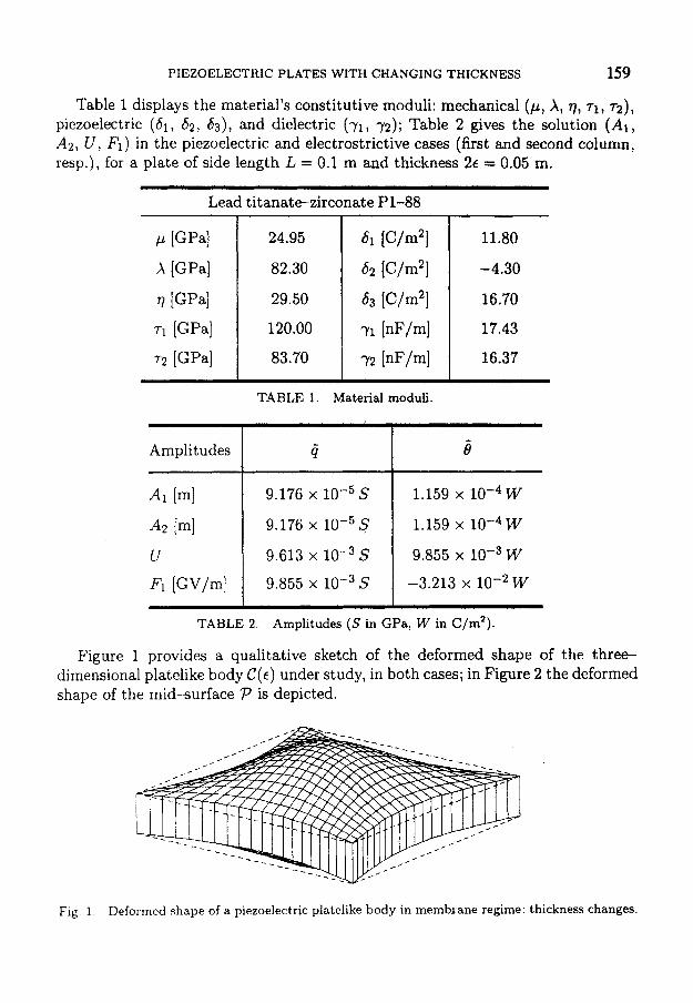
Figure 1 provides a qualitative sketch of the deformed shape of the three- dimensional platelike body C ( E ) under study, in both cases; in Figure 2 the deformed shape of the mid-surface P is depicted.
w
Fig 1 Deformed shape of a piezoelectric platelike body in membrane regime: thickness changes.
160 V. NICOTRA AND P. PODIO-GUIDUGLI
Fig. 2 . Deformed shape of a piezoelectric platelike body in membrane regime: mid-suface changes.
Acknowledgement
This paper was supported by funds from the Italian Research Council (CNR).
References
Bisegna P., Maceri F. , 1996, A consistent theory of thin piezoelectric plates. J . Intell. Mat . Syst.
DeSimone A . , and Podio-Guidugli P., 1995, Centri di form e oscillazioni di spessore nelle piastre.
DiCarlo A . , Podio-Guidugli P., and Williams W.O., 1998, Shells with changing thickness. Forth-
Ikeda T., 1990, Fundamentals of piezoelectricity, Oxford University Press. Maugin G . A . , 1988, Continuum Mechanics of Electromagnetic Solids, North-Holland, Amsterdam. Nicotra V., 1998, Piastre elettromeccaniche capaci di vibrazioni di spessore. Ph.D. thesis, Dipar-
Podio-Guidugli P., 1998, Theory of Elastic Plates, forthcoming. Tiersten H.F., 1969, Lrnear Piezoelectric Plate Vibrations, Plenum Press, New York.
Struct., 7, pp. 372-389.
Atti XI1 Congr. AIMETA, Napoli, 99-104.
coming.
timent,o di Ingegneria Civile, Universita di Roma “Tor Vergata” .