Embed Size (px)
Citation preview

Piezoelectric Equations and ConstantsTo a good approximation, the interaction between the electrical and
mechanical behavior of the piezoelectric medium can be described by the following relationships:
S = sET + dE : D = dT + TE
E = -gT + ( T)-1D : S = sDT + gD
E = Field (Vm-1) : T = Stress (Nm-2) : S = Strain (dimensionless) D = Dielectric Displacement (Cm-2)
The superscripted permittivity and compliance s denotes the quantity kept constant under boundary conditions (e.g T is the permittivity under constant stress)
"d" and "g" are piezoelectric constants:
d = r og
r = relative permittivity (or dielectric constant)
o = permittivity of free space ( 8.85x10⁻¹² F/m)

Piezoelectric Equations and Constants
Because poled piezoelectric ceramics are anisotropic and the direction of polarizing may be freely chosen, a method of identifying the axes of a component is necessary in order to specify its parameters.
The direction of polarization is conventionally taken as the 3 axis, with axes 1 and 2 perpendicular to this. The terms 4, 5 and 6 refer to shear stains associated with the 1, 2 and 3 directions.
Directional Dependence
Piezoelectric Equations and Constants
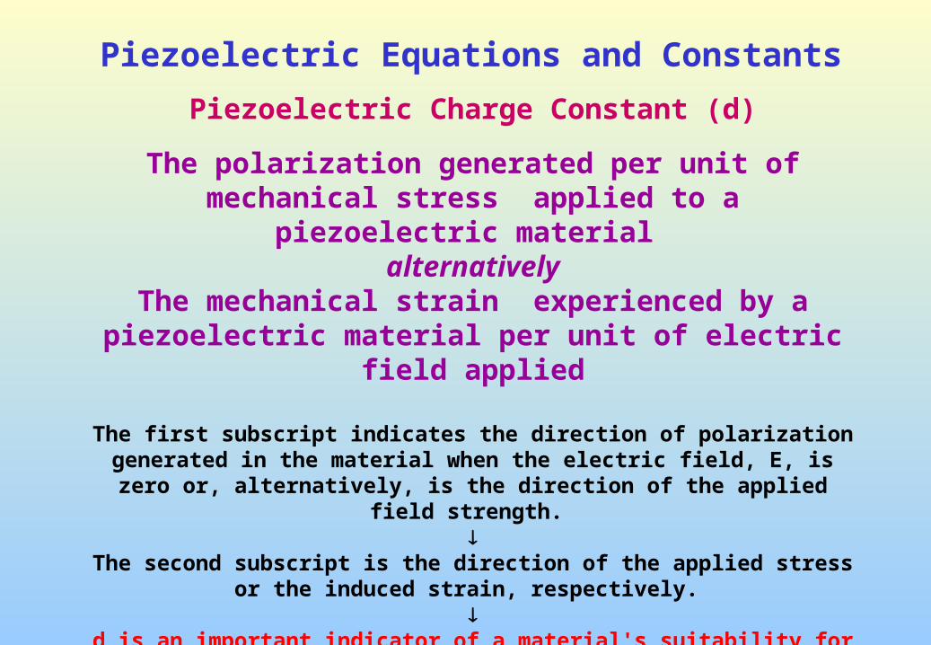
Piezoelectric Charge Constant (d)
The polarization generated per unit of mechanical stress applied to a piezoelectric material
alternatively The mechanical strain experienced by a piezoelectric material
per unit of electric field applied
The first subscript indicates the direction of polarization generated in the material when the electric field, E, is zero or, alternatively, is the direction of the applied
field strength.
The second subscript is the direction of the applied stress or the induced strain, respectively.
d is an important indicator of a material's suitability for strain-dependent
(actuator) applications.

Piezoelectric Equations and Constants
d33 induced polarization in direction 3 (parallel to direction in which
ceramic element is polarized) per unit stress applied in direction 3or
induced strain in direction 3 per unit electric field applied in direction 3
d31 induced polarization in direction 3 (parallel to direction in which
ceramic element is polarized) per unit stress applied in direction 1 (perpendicular to direction in which ceramic element is polarized)
orinduced strain in direction 1 per unit electric field applied in direction 3
d15 induced polarization in direction 1 (perpendicular to direction in
which ceramic element is polarized) per unit shear stress applied about direction 2 (direction 2 perpendicular to direction in which ceramic element
is polarized)or
induced shear strain about direction 2 per unit electric field applied in direction 1

Piezoelectric Equations and Constants
Piezoelectric Voltage Constant (g)
The electric field generated by a piezoelectric material per unit of mechanical stress applied
alternativelyThe mechanical strain experienced by a piezoelectric material per unit of electric displacement applied.
The first subscript to g indicates the direction of the electric field generated in the material, or the direction of the applied electric displacement.
The second subscript is the direction of the applied stress or the induced
strain, respectively.
g is important for assessing a material's suitability for sensing (sensor) applications.

Piezoelectric Equations and Constants
g33 induced electric field in direction 3 (parallel to direction in which ceramic
element is polarized) per unit stress applied in direction 3
or
induced strain in direction 3 per unit electric displacement applied in direction 3
g31 induced electric field in direction 3 (parallel to direction in which ceramic
element is polarized) per unit stress applied in direction 1 (perpendicular to direction in which ceramic element is polarized)
or
induced strain in direction 1 per unit electric displacement applied in direction 3
g15 induced electric field in direction 1 (perpendicular to direction in which
ceramic element is polarized) per unit shear stress applied about direction 2 (direction 2 perpendicular to direction in which ceramic element is polarized)
or
induced shear strain about direction 2 per unit electric displacement applied in direction 1

Definition of the Constants d and g
Constant Definition S.I. Units
d
dielectric displacement developed
applied mechanical stress
(E = constant)
strain developed
applied field
(T = constant)
coulomb/meter2
Pa
meter/meter
volt/meter
C/N
m/V
g
field developed
applied mechanical stress
(D = constant)
strain developed
applied dielectric displacement
(T = constant)
volt/meter
Pa
meter/meter
coulomb/meter2
Vm/N
m2/C

Piezoelectric Equations and ConstantsThere are other parameters to be considered which characterize a
piezoelectric material; of prime importance are the coupling coefficient, loss factor, the mechanical quality factor, and the dielectric permittivity.
The Electromechanical Coupling Coefficient (k)
This parameter determines the efficiency of energy conversion in the component (but not the overall efficiency of the ceramic as a
transducer) and is defined as follows:
(i) For an electrically stressed component
k2 = stored mechanical energy total stored energy
(ii) For a mechanically stressed component
k2 = stored electrical energy total stored energy

Piezoelectric Equations and Constants
The electromechanical coupling factor (k)
An indicator of the effectiveness with which a piezoelectric material converts electrical energy into mechanical energy, or converts mechanical energy
into electrical energy
The first subscript to k denotes the direction along which the electrodes are applied
The second denotes the direction along which the mechanical
energy is applied, or developed
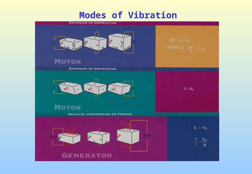
Modes of Vibration

Modes of Vibration

Modes of Vibration

Piezoelectric Parameters and Measurements
The direct and converse effects d constant
D = dX + T E Direct Effect
S = sDX + dE Converse Effect
S = elastic compliance
Ferroelectric ceramics have non-linear properties
D = d X + T E
x = sE X + d E
These coefficients are not all independent
(D =ex and E = hx)
x
iiijij
x
iiijij
he
gd
/
/

Piezoelectric Parameters and MeasurementsElastic behavior can be expressed in terms of
sij = elastic compliance
cij = elastic stiffness
cij Sij
For poled ceramics sjk = skj and cjk = ckj
Only six terms are needed s11, s12, s13, s33, s44, s66 or c11, c12, c13, c33, c44, c66
Short circuit
Open circuit
The Poisson ratio E
E
E
E
ss
ss
33
1313
11
1212
;
D
ij
D
ij
E
ij
E
ij
cs
cs
:
:

Piezoelectric Parameters and Measurements
The values of the piezoelectric properties
Derived from resonance behavior
Suitably Shaped Specimens
The resonance behavior is represented by an equivalent circuit

Piezoelectric Parameters and Measurements
fr and fa : resonant and anti-resonant frequencies
when reactance (Xe) is zero
fs : frequency at which the series arm has zero reactance (X1 = 0)
fp : frequency when resistive component Re is maximum
fm and fn : frequencies for the minimum and maximum impedance Z

Piezoelectric Parameters and Measurements
An important parameter for piezoelectric specimen
The effective electromechanical coupling coefficient keff
keff is related to c0, c1 and fp, fs, fa, fr, fm, and fn
2
22
2
22
2
22
10
12
n
mn
a
ra
p
sp
eff f
ff
f
ff
f
ff
cc
ck
Values for fn and fm are measured by a suitable bridge
(approximation is good if Q of the resonator > 100)
d and g coefficients can be determined from k

Piezoelectric Parameters and MeasurementsFor a piezoceramic rod ( 6 mm in diameter and 15 mm long)
Poled along its length and electroded both ends
For resonance condition
p
sp
p
s
f
ff
f
fk
2tan
233
Dielectric Permittivity can be determined from capacitance C at a frequency well below resonance
A = cross-sectional area of the rod
l = length of the rod
x
33
A
cx
33

Piezoelectric Parameters and Measurements
The elastic compliance is related to the fp
Ds33
22
33
41
lfs pD
= density
Superscript D = Open-circuit = constant electric displacement
)1(
1
2
333333
33
33
33
21
33333333
2
33
33
33
k
dg
skd
k
ss
XX
X
EX
D
E

Piezoelectric Parameters and MeasurementsFor a twin disc of diameter d
Considering a radial mode resonance
s
sp
p
p
f
ffJJf
k
k,,
1 102
2
J0, J1 are Bessel functions and is Poisson’s radio
Curve is very insensitive for of common piezoceramic 0.28 < < 0.32

Piezoelectric Parameters and Measurements
X
EX
sE
p
dg
Skd
fd
s
kk
33
3131
21
11333131
21
2222
11
2231
)(
)2~()1(1
2
1
If minimum impedance |Zm| at resonance is known
Dielectric Q factor = 1/tan
)(41
0 ccZfQ mm

Piezoelectric Parameters and Measurements

Piezoelectric Parameters and MeasurementsIRE Standards Measurements on Piezoelectric Ceramics (IRE 1961)
fr= Resonant Frequency = frequency at minimum impedance
fa= Anti-resonant Frequency = frequency at maximum impedance

Ferroelectric Hysteresis
Sawyer-Tower Circuit Hysteresis Loop
Hysteresis Loop of PZT
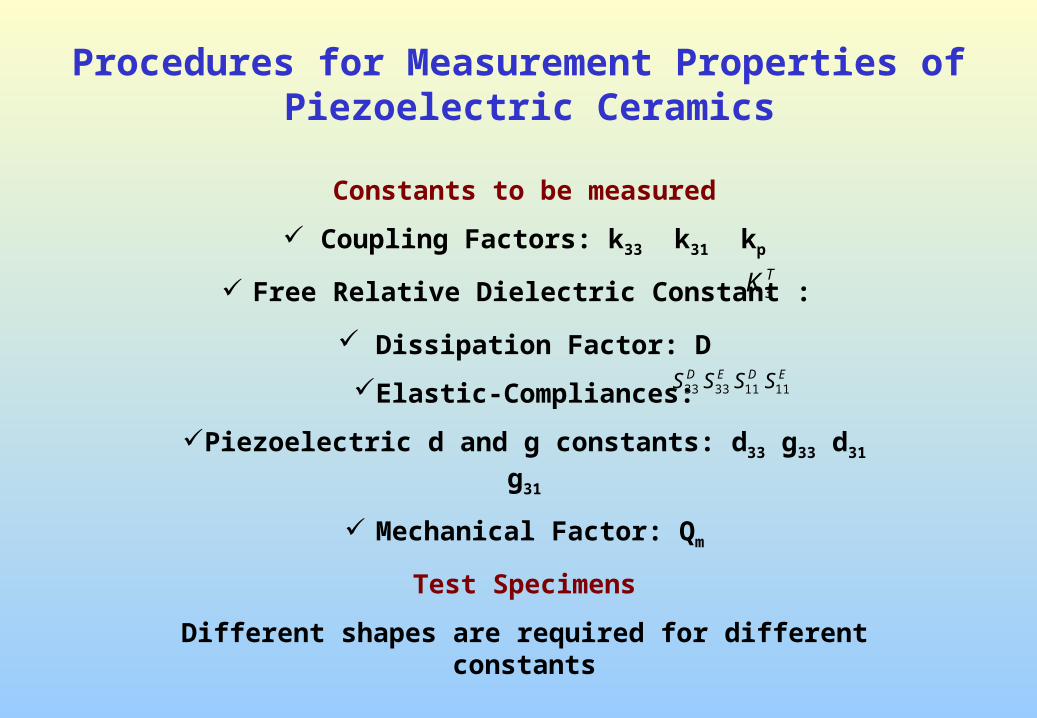
Procedures for Measurement Properties of Piezoelectric Ceramics
Constants to be measured
Coupling Factors: k33 k31 kp
Free Relative Dielectric Constant :
Dissipation Factor: D
Elastic-Compliances:
Piezoelectric d and g constants: d33 g33 d31 g31
Mechanical Factor: Qm
Test Specimens
Different shapes are required for different constants
TK3
EDED SSSS 11113333

Measurement Properties of Piezoelectric CeramicsTest Specimens : Different shapes are required for different constants

Equipment for Simple Measurements
The measurements to be performed on the specimen
1. weight or density
2. physical dimensions
3. free capacitance and dissipation factor
4. frequencies of minimum impedance and maximum impedance
5. The magnitude of the minimum impedance
Equipment required to measure the data
Balance, Micrometer, Capacitance Bridge (capable of 10 pF-10,000 pF)
Oscillator (up to 200 kHz), Frequency counter,
Sensitive electronic voltmeter (200 KHz), variable resistor

Determination of Frequency and Impedance
fm= Meter Peak at the the frequency at minimum impedance
fn= Meter Null at the frequency at maximum impedance
Zm = The magnitude resistance at the frequency of minimum impedance

Calculation of Coupling k33
(Applicable for Length Poled Rod)
Calculation of Coupling k31
(Applicable for Long, Slim, Thickness Poled Specimen)
Calculation of Constants

Determine kp from curve (only for ceramic with Poisson’s Ratio ~ 0.3BT and PZT have Poisson’s Ration ~ 0.3
Calculation of Coupling kp
(Applicable for Thin Discs)
Calculation of Constants
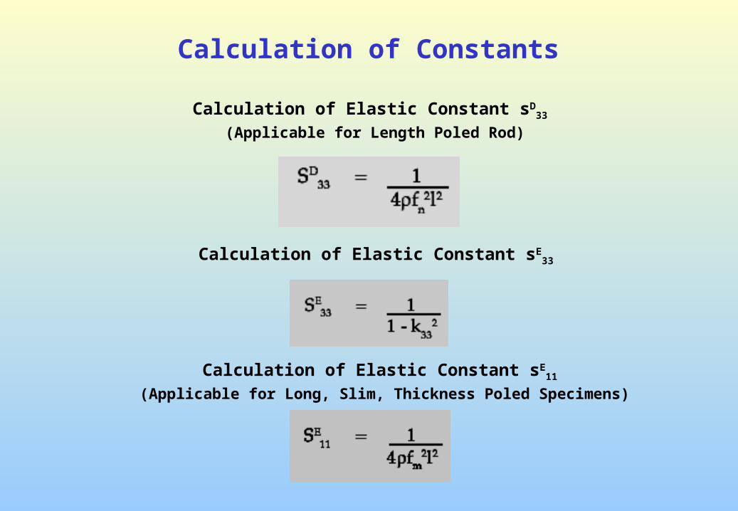
Calculation of Elastic Constant sD33
(Applicable for Length Poled Rod)
Calculation of Elastic Constant sE33
Calculation of Elastic Constant sE11
(Applicable for Long, Slim, Thickness Poled Specimens)
Calculation of Constants

Calculation of Elastic Constant sD11
Calculation of Piezoelectric Constant d33
Calculation of Piezoelectric Constant d33
Calculation of Constants

Calculation of Piezoelectric Constant g33
Calculation of Piezoelectric Constant g11
Calculation of Mechanical Q
Calculation of Constants