Embed Size (px)
Citation preview

www.picotech.com
Power, portability and performance2 or 4 analog channels
MSO models with 16 digital channelsUp to 200 MHz analog bandwidth
Up to 512 MS capture memory1 GS/s real-time sampling
100 000 waveforms per secondBuilt-in arbitrary waveform generator
USB 3.0 connected and powered
Automatic measurements • Mask limit testingAdvanced triggers • Math channels
Spectrum analyzer • Serial decoding
Free technical support and updatesPicoScope, PicoLog and PicoSDK software included
5-year warranty
PC oscilloscopes and MSOs
PicoScope® 3000 Series

PicoScope 3000 Series
IntroductionThe PicoScope 3000 Series PC oscilloscopes are small, light and portable, while offering the high-performance specifications required by engineers in the lab or on the move.
These oscilloscopes offer 2 or 4 analog channels, plus an additional 16 digital channels on the mixed-signal (MSO) models. The flexible, high-quality display options enable you to view and analyze each signal in fine detail. All models come with a built-in function generator and arbitrary waveform generator (AWG).
Operating together with the PicoScope 6 software, these devices offer an ideal, cost-effective package for many applications, including embedded systems design, research, test, education, service, and repair.

PicoScope 3000 Series
High bandwidth, high sampling rate, deep memoryDespite their compact size and low cost, there is no compromise on performance, with input bandwidths up to 200 MHz. This bandwidth is matched by a real-time sampling rate of up to 1 GS/s, enabling detailed display of high frequencies. For repetitive signals, the maximum effective sampling rate can be boosted to 10 GS/s using equivalent time sampling (ETS) mode. With a sampling rate of at least five times the input bandwidth, PicoScope 3000 Series oscilloscopes are well equipped to capture high-frequency signal detail.
Many other oscilloscopes have high maximum sampling rates, but without deep memory they cannot sustain these rates on long timebases. The PicoScope 3000 Series offers up to 512 million samples capture memory, enabling the PicoScope 3406D MSO to sample at 1 GS/s all the way down to 50 ms/div (500 ms total capture time).
Managing all this data calls for some powerful tools. There’s a set of zoom buttons, plus an overview window that lets you zoom and reposition the display by simply dragging with the mouse or touchscreen. Zoom factors of several million are possible. Other tools such as the waveform buffer navigator, mask limit testing, serial decoding, DeepMeasure and hardware acceleration work with the deep memory, making the PicoScope 3000 series some of the most capable oscilloscopes on the market.

PicoScope 3000 Series
Application examples
Testing on the move The PicoScope 3000 Series oscilloscopes slip easily into a laptop bag, so you don’t need to carry bulky benchtop instruments to perform on-site troubleshooting. Being powered via a USB connection, you can simply plug your PicoScope into your laptop and use it for measuring wherever you are. The PC connection also makes saving and sharing your data quick and easy: in a matter of seconds you can save your scope traces to review later, or attach the complete data file to an email for analysis by other engineers away from the test site. As PicoScope 6 is free to download by anyone, colleagues can use the full capabilities of the software, such as serial decoding and spectrum analysis, without needing an oscilloscope themselves.
Embedded debuggingYou can test and debug a complete signal-processing chain using a PicoScope 3406D MSO.
Use the built-in arbitrary waveform generator (AWG) to inject single-shot or continuous analog signals. The response of your system can then be observed in both the analog domain, using the four 200 MHz input channels, and in the digital domain with 16 digital inputs at up to 100 MHz. Follow the analog signal through the system while simultaneously using the built-in serial decoding function to view the output of an I2C or SPI ADC.
If your system drives a DAC in response to the analog input changing, you can decode the I2C or SPI communication to that as well as its analog output. This can all be performed simultaneously using the 16 digital and 4 analog channels.
Using the deep 512 MS capture memory, you can capture the complete response of your system without sacrificing the sampling rate, and zoom in on the captured data to find glitches and other points of interest.

PicoScope 3000 Series
PicoScope features
Advanced displayPicoScope 6 software dedicates the majority of the display area to the waveform, ensuring that the maximum amount of data is visible at all times. The size of the display is only limited by the size of your computer’s monitor, so even with a laptop, the viewing area is much bigger, with much higher resolution, than that of a benchtop scope.
With such a large display area available, you can create a customizable split-screen display and view multiple channels or different views of the same signal at the same time – the software can even show multiple oscilloscope and spectrum analyzer views at once. Each view has separate zoom, pan and filter settings for ultimate flexibility.
You can control the PicoScope 6 software using a mouse, touchscreen or customizable keyboard shortcuts.

PicoScope 3000 Series
Advanced triggersThe PicoScope 3000 Series offers an industry-leading set of advanced triggers including pulse width, windowed and dropout.
The digital trigger available on MSO models allows you to trigger the scope when any or all of the 16 digital inputs match a user-defined pattern. You can specify a condition for each channel individually, or set up a pattern for all channels at once using a hexadecimal or binary value.
You can also use the logic trigger to combine the digital trigger with an edge or window trigger on any of the analog inputs, for example to trigger on data values in a clocked parallel bus.
Digital triggering architectureIn 1991, Pico Technology pioneered the use of digital triggering using the actual digitized data. Traditionally, digital oscilloscopes have used an analog trigger architecture based on comparators, which can cause time and amplitude errors that cannot always be calibrated out. Additionally, the use of comparators can often limit the trigger sensitivity at high bandwidths and can create a long trigger rearm delay.
Pico’s technique of fully digital triggering reduces trigger errors and allows our oscilloscopes to trigger on the smallest signals, even at the full bandwidth, so you can set trigger levels and hysteresis with high precision and resolution.
The digital triggering architecture also reduces the rearm delay. Combined with the segmented memory, this enables you to use rapid triggering to capture 10 000 waveforms in 6 ms.
PicoScope 3000 Series
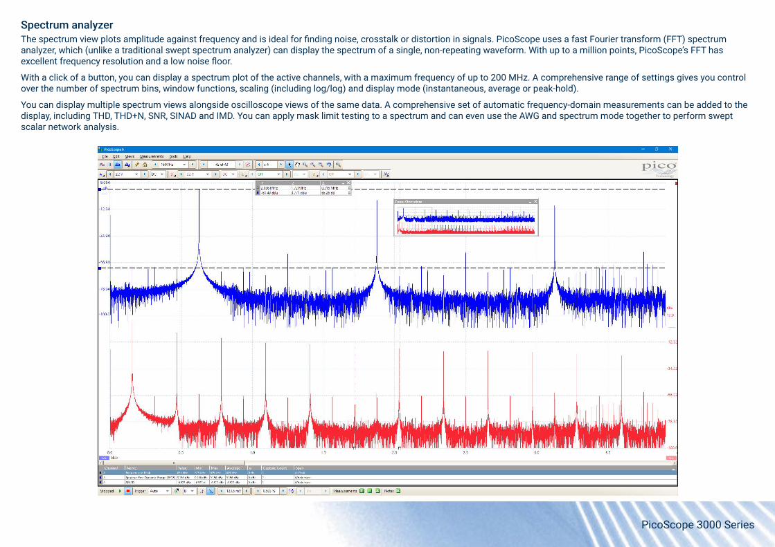
Spectrum analyzerThe spectrum view plots amplitude against frequency and is ideal for finding noise, crosstalk or distortion in signals. PicoScope uses a fast Fourier transform (FFT) spectrum analyzer, which (unlike a traditional swept spectrum analyzer) can display the spectrum of a single, non-repeating waveform. With up to a million points, PicoScope’s FFT has excellent frequency resolution and a low noise floor.
With a click of a button, you can display a spectrum plot of the active channels, with a maximum frequency of up to 200 MHz. A comprehensive range of settings gives you control over the number of spectrum bins, window functions, scaling (including log/log) and display mode (instantaneous, average or peak-hold).
You can display multiple spectrum views alongside oscilloscope views of the same data. A comprehensive set of automatic frequency-domain measurements can be added to the display, including THD, THD+N, SNR, SINAD and IMD. You can apply mask limit testing to a spectrum and can even use the AWG and spectrum mode together to perform swept scalar network analysis.

PicoScope 3000 Series
Persistence modePicoScope’s persistence mode options allow you to see old and new data superimposed, making it easy to spot glitches and dropouts and estimate their relative frequency – useful for displaying and interpreting complex analog signals such as video waveforms and amplitude-modulated signals. Color-coding and intensity-grading show which areas are stable and which are intermittent. Choose between Analog Intensity, Digital Color and Fast display modes or create your own custom setup.
An important specification to understand when evaluating oscilloscope performance, especially in persistence mode, is the waveform update rate, which is expressed as waveforms per second. While the sampling rate indicates how frequently the oscilloscope samples the input signal within one waveform or cycle, the waveform capture rate refers to how quickly an oscilloscope acquires waveforms.
Oscilloscopes with high waveform capture rates provide better visual insight into signal behavior and dramatically increase the probability that the oscilloscope will quickly capture transient anomalies such as jitter, runt pulses and glitches – that you may not even know exist.
The PicoScope 3000 Series’ HAL3 hardware acceleration means that, in fast persistence mode, update rates of up to 100 000 waveforms per second are achievable.

PicoScope 3000 Series
Arbitrary waveform and function generatorAll PicoScope 3000 Series oscilloscopes have a built-in function generator and arbitrary waveform generator (AWG). The function generator can produce sine, square, triangle and DC level waveforms, and many more besides, while the AWG allows you to import waveforms from data files or create and modify them using the built-in graphical AWG editor.
As well as level, offset and frequency controls, advanced options allow you to sweep over a range of frequencies. Combined with the advanced spectrum mode, with options including peak hold, averaging and linear/log axes, this creates a powerful tool for testing amplifier and filter responses.

PicoScope 3000 Series
HAL3 hardware accelerationMany oscilloscopes struggle when deep memory is enabled: the screen update rate slows and the controls can become unresponsive. The PicoScope 3000 Series oscilloscopes avoid this limitation with the use of a dedicated hardware acceleration engine. This parallel design effectively creates the waveform image to be displayed on the PC screen and allows the continuous capture and display of over 440 000 000 samples every second.
For example, the PicoScope 3206D can sample at 1 GS/s on timebases as long as 20 ms/div, capturing 200 million samples per waveform, and still update the screen several times per second. That’s around 500 million sample points each second! The hardware acceleration engine eliminates any concerns about the USB connection or PC processor being a bottleneck.

PicoScope 3000 Series
High-end features as standardBuying a PicoScope is not like making a purchase from other oscilloscope companies, where increased functionality can considerably raise the price. PicoScopes are all-inclusive instruments, with no need for expensive upgrades to unlock the hardware. Other advanced features such as resolution enhancement, mask limit testing, serial decoding, advanced triggering, automatic measurements, math channels (including the ability to plot frequency and duty cycle against time), XY mode and segmented memory are all included in the price.
SuperSpeed USB 3.0 connectionPicoScope 3000 Series oscilloscopes feature a USB 3.0 connection, providing lightning-fast saving of waveforms while retaining compatibility with older USB standards.
PicoSDK® supports continuous streaming to the host computer at up to 125 MS/s.
The USB connection not only allows high-speed data acquisition and transfer, but also makes printing, copying, saving and emailing your data from the field quick and easy.
High signal integrityCareful front-end design and shielding reduce noise, crosstalk and harmonic distortion, meaning we are proud to publish the specifications of our scopes in detail. Decades of oscilloscope design experience can be seen in improved pulse response and bandwidth flatness, and low distortion. PicoScope 3000 Series oscilloscopes feature 10 input ranges from ±20 mV to ±20 V full scale and a typical dynamic performance of up to 52 dB SFDR. The result is simple: when you probe a circuit, you can trust in the waveform you see on the screen.

PicoScope 3000 Series
PicoScope softwareThe PicoScope software display can be as basic or as detailed as you need. Begin with a single view of one channel, and then expand the display to include up to four live analog and 16 digital channels (model-dependent), plus math channels and reference waveforms. Display multiple scope and spectrum views with automatic or custom layouts and quickly access all the most frequently-used controls from the toolbars, leaving the display clear for your waveforms.
Tools menuHome to our award-winning DeepMeasure feature, along with custom probes, serial decoding, reference waveforms, mask limit testing, alarms and macros.
Touchscreen controls:Handy buttons make fine adjustments easy on touchscreen devices.
Trigger marker: Drag the marker to adjust the trigger threshold and pre-trigger time.
Buffer Navigation toolbar: PicoScope can record up to 10 000 of your most recent waveforms. Click through the buffer to look for intermittent events, or use the Buffer Overview thumbnails.
Zooming and Scrolling toolbar: PicoScope makes it easy to zoom in on waveforms, with straightforward zoom-in, zoom-out and pan tools.
Signal generator:Generates standard signals or arbitrary waveforms. Includes frequency sweep mode.
Ruler legend:Absolute and differential ruler measurements are listed here.
Rulers: Each axis has two rulers that you can drag across the screen to make quick measurements.
Zoom Overview window:Click and drag for quick navigation and adjustment of zoomed views.
Spectrum view: View frequency-domain data alongside time-domain waveforms or in the dedicated spectrum mode.
Automatic measurements: Add as many calculated time- and frequency-domain measurements as you need, along with statistical parameters showing their variability.
Trigger toolbar: Quick access to the main controls, with advanced triggers in a pop-up window.
Auto Setup button:Let PicoScope configure the collection time and input range for a correctly scaled display.
Channel options: Adjust settings specific to each channel here.
Adjustable axes: Move the vertical axes up and down the display and vary their scale and offset. PicoScope can also rearrange the axes automatically.
Views: Add new scope and spectrum views with automatic or custom layouts.
PicoScope 3000 Series
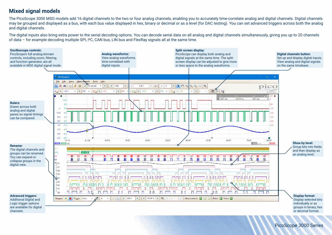
Mixed signal modelsThe PicoScope 3000 MSO models add 16 digital channels to the two or four analog channels, enabling you to accurately time-correlate analog and digital channels. Digital channels may be grouped and displayed as a bus, with each bus value displayed in hex, binary or decimal or as a level (for DAC testing). You can set advanced triggers across both the analog and digital channels.
The digital inputs also bring extra power to the serial decoding options. You can decode serial data on all analog and digital channels simultaneously, giving you up to 20 channels of data – for example decoding multiple SPI, I²C, CAN bus, LIN bus and FlexRay signals all at the same time.
Oscilloscope controls:PicoScope’s full analog-domain controls, including zoom, filtering, and function generator, are all available in MSO digital signal mode.
Advanced triggers:Additional Digital and Logic trigger options are available for digital channels.
Rename:The digital channels and groups can be renamed. You can expand or collapse groups in the digital view.
Rulers:Drawn across both analog and digital panes so signal timings can be compared.
Analog waveforms:View analog waveforms time-correlated with digital inputs.
Split-screen display:PicoScope can display both analog and digital signals at the same time. The split-screen display can be adjusted to give more or less space to the analog waveforms.
Digital channels button:Set up and display digital inputs. View analog and digital signals on the same timebase.
Show by level:Group bits into fields and then display as an analog level.
Display format:Display selected bits individually or as groups in binary, hex or decimal format.

PicoScope 3000 Series
DeepMeasure™One waveform, millions of measurements
Measurement of waveform pulses and cycles is key to verification of the performance of electrical and electronic devices.
DeepMeasure delivers automatic measurements of important waveform parameters, such as pulse width, rise time and voltage, for every individual cycle in the captured waveforms. Up to a million waveform cycles can be displayed with each triggered acquisition. Results can be easily sorted, analyzed and correlated with the waveform display, or exported as a CSV file or spreadsheet for further analysis.
For example, use DeepMeasure with PicoScope’s rapid trigger mode to capture 10 000 pulses and quickly find those with the largest or smallest amplitude, or use your scope’s deep memory to record a million cycles of one waveform and export the rise time of every single edge for statistical analysis.
Automatic measurementsPicoScope allows you to display a table of calculated measurements for troubleshooting and analysis. Using the built-in measurement statistics you can see the average, standard deviation, maximum and minimum of each measurement as well as the live value.
You can add as many measurements as you need on each view – 19 different measurements are available in scope mode and 11 in spectrum mode. For information on these measurements, see Automatic measurements in the Specifications table.

PicoScope 3000 Series
Math channels and filtersWith PicoScope 6 you can select simple functions such as addition and inversion, or open the equation editor to create complex functions involving filters (lowpass, highpass, bandpass and bandstop filters), trigonometry, exponentials, logarithms, statistics, integrals and derivatives.
Display up to eight real or calculated channels in each scope view. If you run out of space, just open another scope view and add more. You can also use math channels to reveal new details in complex signals, for example graphing the changing duty cycle or frequency of your signal over time.
Custom probesThe custom probes feature allows you to correct for gain, attenuation, offsets and nonlinearities in probes, sensors or transducers that you connect to the oscilloscope. This could be used to scale the output of a current probe so that it correctly displays amperes. A more advanced use would be to scale the output of a nonlinear temperature sensor using the table lookup function.
Definitions for standard Pico-supplied oscilloscope probes and current clamps are included, but you can also create your own and save them for later use.
PicoScope 3000 Series
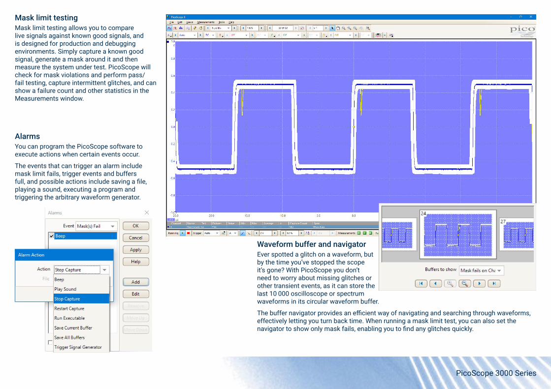
Mask limit testingMask limit testing allows you to compare live signals against known good signals, and is designed for production and debugging environments. Simply capture a known good signal, generate a mask around it and then measure the system under test. PicoScope will check for mask violations and perform pass/fail testing, capture intermittent glitches, and can show a failure count and other statistics in the Measurements window.
Waveform buffer and navigatorEver spotted a glitch on a waveform, but by the time you’ve stopped the scope it’s gone? With PicoScope you don’t need to worry about missing glitches or other transient events, as it can store the last 10 000 oscilloscope or spectrum waveforms in its circular waveform buffer.
The buffer navigator provides an efficient way of navigating and searching through waveforms, effectively letting you turn back time. When running a mask limit test, you can also set the navigator to show only mask fails, enabling you to find any glitches quickly.
AlarmsYou can program the PicoScope software to execute actions when certain events occur.
The events that can trigger an alarm include mask limit fails, trigger events and buffers full, and possible actions include saving a file, playing a sound, executing a program and triggering the arbitrary waveform generator.

PicoScope 3000 Series
PicoLog® 6 softwarePicoScope 3000 Series oscilloscopes are also supported by the PicoLog 6 data logging software, allowing you to view and record signals on multiple units in one capture.
PicoLog 6 allows sample rates of up to 1 kS/s per channel, and is ideal for long-term observation of general parameters, such as voltage or current levels, on several channels at the same time, whereas the PicoScope 6 software is more suitable for waveshape or harmonic analysis.
You can also use PicoLog 6 to view data from your oscilloscope alongside a data logger or other device. For example, you could measure voltage and current with your PicoScope and plot both against temperature using a TC-08 thermocouple data logger, or humidity with a DrDAQ multipurpose data logger.
PicoLog 6 is available for Windows, macOS and Linux, including Raspberry Pi OS.

PicoScope 3000 Series
PicoSDK® – write your own appsOur software development kit, PicoSDK, allows you to write your own software and includes drivers for Windows, macOS and Linux. Example code supplied on our GitHub organization page shows how to interface to third-party software packages such as NI LabVIEW and MathWorks MATLAB.
Amongst other features, the drivers support data streaming, a mode that captures continuous gap-free data directly to your PC at rates of up to 125 MS/s (when taking advantage of the PicoScope 3000 Series’ USB 3.0 connection), so you are not limited by the size of your scope’s capture memory. Sampling rates in streaming mode are subject to PC specifications and application loading.
There is also an active community of PicoScope 6 users who share both code and whole applications on our Test and Measurement Forum and the PicoApps section of the website. The Frequency Response Analyzer shown here is one of the most popular of these applications.
OEM and custom applicationsPico Technology has supplied products for use in custom test and monitoring solutions since 1991. Pico products have been used as core components in a broad range of demanding applications for clients including Kistler, Techimp and the GSI/FAIR particle accelerator facility in Darmstadt, Germany.
Our technical support team provides support and guidance for you to develop your custom test requirements, including software development using PicoSDK, and system integration.
Read more about custom and OEM applications, including examples and case studies, at picotech.com/library/oem-custom-applications.
Copyright © 2014-2021 Aaron Hexamer. Distributed under GNU GPL3.

PicoScope 3000 Series
Kit contents and accessories Your PicoScope 3000 Series oscilloscope kit contains the following items:
• PicoScope 3000 Series oscilloscope• Quick start guide• USB 3.0 cable, 1.8 m• AC power adaptor (4-channel models only)
ProbesEach oscilloscope comes with probes specifically trimmed to match its performance.
50, 70 and 100 MHz models: 2/4 x TA375 100 MHz probes
200 MHz models: 2/4 x TA386 200 MHz probes.
MSO kit contentsMixed-signal models come with extra accessories:
• TA136 20-way digital input cable for MSOs• 2 x TA139 pack of 12 logic test clips
USB connectivity and powerAll PicoScope 3000 Series oscilloscopes are supplied with a USB 3.0 cable for SuperSpeed connectivity.
For models with four analog channels, the supplied AC power adaptor may be required if the USB port provides less than 1200 mA to the instrument.
TA136 20-way digital input cable for MSOs
Oscilloscope probe
TA139 logic test clips, pack of 12

PicoScope 3000 Series
2-channel models
Channels A and B
External triggerAWG/function generator
Probe compensation pin
Ground terminal
USB 3.0 port
4-channel models
Channels A, B, C and D
External trigger
AWG/function generator
Probe compensation pin
Ground terminal
USB 3.0 port
DC power input
4-channel MSO models
Channels A, B, C and D
Probe compensation pin16 digital inputs
AWG/function generator
Ground terminalUSB 3.0 port
DC power input
2-channel MSO models
AWG/function generator
Ground terminalUSB 3.0 port
Channels A and BProbe compensation pin
16 digital inputs
Input and output connections

PicoScope 3000 Series
PicoScope 3000 Series specificationsPicoScope software and drivers are subject to updates and changes in functionality. We recommend you check the most recent specifications at picotech.com.
PicoScope 3203D and
3203D MSO
PicoScope 3403D and
3403D MSO
PicoScope 3204D and
3204D MSO
PicoScope 3404D and
3404D MSO
PicoScope 3205D and
3205D MSO
PicoScope 3405D and
3405D MSO
PicoScope 3206D and
3206D MSO
PicoScope 3406D and
3406D MSOVertical (analog channels)Input channels 2 4 2 4 2 4 2 4Bandwidth (–3dB) 50 MHz 70 MHz 100 MHz 200 MHzRise time (calculated) 7.0 ns 5.3 ns 3.5 ns 1.75 nsBandwidth limit 20 MHz, selectableVertical resolution 8 bitsEnhanced vertical resolution 12 bits in PicoScope softwareInput type Single-ended, BNC(f) connector Input characteristics 1 MΩ ±1% ∥ 14 pF ±1 pFInput coupling AC/DCInput sensitivity 4 mV/div to 4 V/div (10 vertical divisions)Input ranges (full scale) ±20 mV, ±50 mV, ±100 mV, ±200 mV, ±500 mV, ±1 V, ±2 V, ±5 V, ±10 V, ±20 VDC accuracy ±(3% of full scale + 200 μV)
Analog offset range (vertical position adjustment)
±250 mV (±20 mV, ±50 mV, ±100 mV, ±200 mV ranges)±2.5 V (±500 mV, ±1 V, ±2 V ranges)±20 V (±5 V, ±10 V, ±20 V ranges)
Offset adjustment accuracy ±1% of offset setting, additional to DC accuracyOvervoltage protection ±100 V (DC + AC peak)Vertical (digital channels: MSO models only)Input channels 16 channels (2 ports of 8 channels)Input connectors 2.54 mm pitch, 10 x 2-way connectorMaximum input frequency 100 MHz (200 Mb/s)Minimum detectable pulse width 5 nsInput characteristics 200 kΩ ±2% ∥ 8 pF ±2 pFInput dynamic range ±20 VThreshold range ±5 VThreshold grouping Two independent threshold controls. Port 0: D0 to D7, Port 1: D8 to D15.Threshold selection TTL, CMOS, ECL, PECL, user-definedThreshold accuracy < ±350 mV including hysteresisHysteresis < ±250 mVMinimum input voltage swing 500 mV peak to peak
PicoScope 3000 Series
PicoScope 3203D and
3203D MSO
PicoScope 3403D and
3403D MSO
PicoScope 3204D and
3204D MSO
PicoScope 3404D and
3404D MSO
PicoScope 3205D and
3205D MSO
PicoScope 3405D and
3405D MSO
PicoScope 3206D and
3206D MSO
PicoScope 3406D and
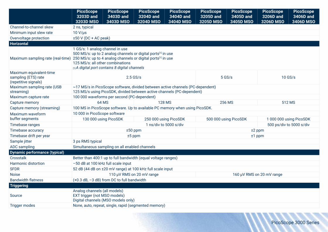
3406D MSOChannel-to-channel skew 2 ns, typicalMinimum input slew rate 10 V/µsOvervoltage protection ±50 V (DC + AC peak)Horizontal
Maximum sampling rate (real-time)
1 GS/s: 1 analog channel in use500 MS/s: up to 2 analog channels or digital ports[1] in use250 MS/s: up to 4 analog channels or digital ports[1] in use125 MS/s: all other combinations[1] A digital port contains 8 digital channels
Maximum equivalent-time sampling (ETS) rate (repetitive signals)
2.5 GS/s 5 GS/s 10 GS/s
Maximum sampling rate (USB streaming)
~17 MS/s in PicoScope software, divided between active channels (PC-dependent)125 MS/s using PicoSDK, divided between active channels (PC-dependent)
Maximum capture rate 100 000 waveforms per second (PC-dependent)Capture memory 64 MS 128 MS 256 MS 512 MSCapture memory (streaming) 100 MS in PicoScope software. Up to available PC memory when using PicoSDK.Maximum waveform buffer segments
10 000 in PicoScope software130 000 using PicoSDK 250 000 using PicoSDK 500 000 using PicoSDK 1 000 000 using PicoSDK
Timebase ranges 1 ns/div to 5000 s/div 500 ps/div to 5000 s/divTimebase accuracy ±50 ppm ±2 ppmTimebase drift per year ±5 ppm ±1 ppmSample jitter 3 ps RMS typicalADC sampling Simultaneous sampling on all enabled channelsDynamic performance (typical)Crosstalk Better than 400:1 up to full bandwidth (equal voltage ranges)Harmonic distortion –50 dB at 100 kHz full scale inputSFDR 52 dB (44 dB on ±20 mV range) at 100 kHz full scale inputNoise 110 µV RMS on 20 mV range 160 µV RMS on 20 mV rangeBandwidth flatness (+0.3 dB, –3 dB) from DC to full bandwidthTriggering
SourceAnalog channels (all models)EXT trigger (not MSO models)Digital channels (MSO models only)
Trigger modes None, auto, repeat, single, rapid (segmented memory)

PicoScope 3000 Series
PicoScope 3203D and
3203D MSO
PicoScope 3403D and
3403D MSO
PicoScope 3204D and
3204D MSO
PicoScope 3404D and
3404D MSO
PicoScope 3205D and
3205D MSO
PicoScope 3405D and
3405D MSO
PicoScope 3206D and
3206D MSO
PicoScope 3406D and
3406D MSOPre-trigger capture Up to 100% of capture sizePost-trigger delay Up to 4 billion samples, selectable in 1 sample steps Trigger rearm time < 0.7 µs at 1 GS/s sampling rateMaximum trigger rate Up to 10 000 waveforms in a 6 ms burst at 1 GS/s sampling rate, typicalTriggering for analog channelsAdvanced trigger types Edge, window, pulse width, interval, window pulse width, level dropout, window dropout, runt, logicTrigger types (ETS mode) Rising edge, falling edge (available on channel A only)Trigger sensitivity Digital triggering provides 1 LSB accuracy up to full bandwidth of scopeTrigger sensitivity (ETS mode) 10 mV peak to peak at full bandwidth, typicalTriggering for digital inputs – MSO models onlyTrigger types Pattern, edge, combined pattern and edge, pulse width, dropout, interval, logicExternal trigger input – not MSO modelsConnector type Front panel BNCTrigger types Edge, pulse width, dropout, interval, logicInput characteristics 1 MΩ ∥ 14 pFBandwidth 50 MHz 70 MHz 100 MHz 200 MHzThreshold range ±5 VCoupling DCOvervoltage protection ±100 V (DC + AC peak)

PicoScope 3000 Series
Common specificationsAll PicoScope 3000 Series oscilloscopes
Function generatorStandard output signals Sine, square, triangle, DC voltage, ramp up, ramp down, sinc, Gaussian, half-sine.
Pseudorandom output signals White noise, selectable amplitude and offset within output voltage range.Pseudorandom binary sequence (PRBS), selectable high and low levels within output voltage range, selectable bit rate up to 1 Mb/s
Standard signal frequency 0.03 Hz to 1 MHzSweep modes Up, down, dual with selectable start/stop frequencies and increments
Triggering Free-run, or from 1 to 1 billion counted waveform cycles or frequency sweeps. Triggered from scope trigger, external trigger (where present) or manually.
Output frequency accuracy As oscilloscopeOutput frequency resolution < 0.01 HzOutput voltage range ±2 VOutput voltage adjustments Signal amplitude and offset adjustable in approximately 1 mV steps within overall ±2 V rangeAmplitude flatness < 0.5 dB to 1 MHz, typicalDC accuracy ±1% of full scaleSFDR > 60 dB, 10 kHz full scale sine wave, typicalOutput impedance 600 Ω
Connector type Front panel BNC (non-MSO models)Rear panel BNC (MSO models)
Overvoltage protection ±20 VArbitrary waveform generator[2]
Update rate 20 MS/sBuffer size 32 kSResolution 12 bits (output step size approximately 1 mV)Bandwidth (–3 dB) > 1 MHzRise time (10% to 90%) < 120 ns[2] For additional AWG specifications, see Function generator specifications above.Probe compensation pinOutput impedance 600 ΩOutput frequency 1 kHzOutput level 2 V peak to peak, typicalSpectrum analyzerFrequency range DC to maximum bandwidth of scopeDisplay modes Magnitude, average, peak holdY axis Logarithmic (dbV, dBu, dBm, arbitrary dB) or linear (volts)X axis Linear or logarithmic

PicoScope 3000 Series
All PicoScope 3000 Series oscilloscopesWindowing functions Rectangular, Gaussian, triangular, Blackman, Blackman-Harris, Hamming, Hann, flat-topNumber of FFT points Selectable from 128 to 1 million in powers of 2Math channels
Functions −x, x+y, x−y, x*y, x/y, x^y, sqrt, exp, ln, log, abs, norm, sign, sin, cos, tan, arcsin, arccos, arctan, sinh, cosh, tanh, freq, derivative, integral, min, max, average, peak, delay, duty, highpass, lowpass, bandpass, bandstop, coupler
Operands All analog and digital input channels, reference waveforms, time, constants, πAutomatic measurements
Oscilloscope mode AC RMS, true RMS, cycle time, DC average, duty cycle, negative duty cycle, edge count, rising edge count, falling edge count, falling rate, fall time, frequency, high pulse width, low pulse width, maximum, minimum, peak to peak, rise time, rising rate.
Spectrum mode Frequency at peak, amplitude at peak, average amplitude at peak, total power, THD %, THD dB, THD+N, SFDR, SINAD, SNR, IMDStatistics Minimum, maximum, average, standard deviationDeepMeasure™
Parameters Cycle number, cycle time, frequency, low pulse width, high pulse width, duty cycle (high), duty cycle (low), rise time, fall time, undershoot, overshoot, maximum voltage, minimum voltage, voltage peak to peak, start time, end time
Serial decoding
Protocols 1-Wire, ARINC 429, CAN, CAN FD, DALI, DCC, DMX512, Ethernet 10BASE-T & 100BASE-TX, FlexRay, I²C, I²S, LIN, Manchester, Modbus ASCII, Modbus RTU, PS/2, SENT Fast & Slow, SPI, UART (RS-232 / RS-422 / RS-485), USB 1.0/1.1
Mask limit testingStatistics Pass/fail, failure count, total countDisplayInterpolation Linear or sin(x)/xPersistence modes Digital color, analog intensity, fast, advancedOutput file formats bmp, csv, gif, animated gif, jpg, mat, pdf, png, psdata, pssettings, txtOutput functions Copy to clipboard, printGeneral specificationsConnectivity USB 3.0 SuperSpeed (USB 2.0 compatible) type B
Power requirements Powered from a single USB 3.0 port4-channel models: AC adaptor included for use with USB ports that supply less than 1200 mA
Ground terminal M4 screw terminal, rear panelDimensions 190 mm x 170 mm x 40 mm including connectorsWeight < 0.5 kg
Temperature range Operating: 0 °C to 40 °C (15 °C to 30 °C for stated accuracy). Storage: –20 °C to 60 °C
Humidity range Operating: 5% RH to 80% RH non-condensing Storage: 5% RH to 95% RH non-condensing
Altitude range Up to 2000 mPollution degree Pollution degree 2

PicoScope 3000 Series
All PicoScope 3000 Series oscilloscopesSafety approvals Designed to EN 61010-1:2010EMC approvals Tested to EN 61326-1:2013 and FCC Part 15 Subpart BEnvironmental compliance RoHS, REACH and WEEE compliantSoftware availability and requirements (hardware requirements as operating system)Windows software (32-bit or 64-bit)[3] PicoScope 6, PicoLog 6, PicoSDKmacOS software (64-bit)[3] PicoScope 6 Beta (including drivers), PicoLog 6 (including drivers)
Linux software (64-bit)[3] PicoScope 6 Beta software and drivers, PicoLog 6 (including drivers)See Linux Software and Drivers to install drivers only
Raspberry Pi 3B and 4B (Raspberry Pi OS)[3] PicoLog 6 (including drivers)See Linux Software and Drivers to install drivers only
[3] See picotech.com/downloads for more information, including supported OS versions.
Languages supported, PicoScope 6 Simplified Chinese, Czech, Danish, Dutch, English, Finnish, French, German, Greek, Hungarian, Italian, Japanese, Korean, Norwegian, Polish, Portuguese, Romanian, Russian, Spanish, Swedish, Turkish
Languages supported, PicoLog 6 Simplified Chinese, Dutch, English (UK), English (US), French, German, Italian, Japanese, Korean, Russian, Spanish

PicoScope 3000 Series
Ordering informationOrder code Description Bandwidth (MHz) Channels Capture memory (MS)PP958 PicoScope 3203D 50 2 64PP956 PicoScope 3203D MSO 50 2+16 64PP962 PicoScope 3403D 50 4 64PP957 PicoScope 3403D MSO 50 4+16 64PP959 PicoScope 3204D 70 2 128PP931 PicoScope 3204D MSO 70 2+16 128PP963 PicoScope 3404D 70 4 128PP934 PicoScope 3404D MSO 70 4+16 128PP960 PicoScope 3205D 100 2 256PP932 PicoScope 3205D MSO 100 2+16 256PP964 PicoScope 3405D 100 4 256PP935 PicoScope 3405D MSO 100 4+16 256PP961 PicoScope 3206D 200 2 512PP933 PicoScope 3206D MSO 200 2+16 512PP965 PicoScope 3406D 200 4 512PP936 PicoScope 3406D MSO 200 4+16 512
AccessoriesOrder code DescriptionTA375 TA375 Passive oscilloscope probe: 100 MHz bandwidth 1:1/10:1 switchableTA386 TA386 Passive oscilloscope probe: 200 MHz bandwidth 1:1/10:1 switchableTA136 TA136 20-way digital input cable for MSOsTA139 TA139 Logic test clips, pack of 12PS011 PS011 5 V AC power adaptorTA155 TA155 USB 3.0 cable, 1.8 mPP969 PP969 Hard carry case – medium
Calibration serviceOrder code DescriptionCC017 Calibration certificate for PicoScope 3000 Series oscilloscope

www.picotech.com
@picotechnologyltdPico Technology Pico Technology@LifeAtPico @picotech
United Kingdom global headquarters:
Pico TechnologyJames HouseColmworth Business ParkSt. NeotsCambridgeshirePE19 8YPUnited Kingdom
+44 (0) 1480 396 395 [email protected]
North America regional office:
Pico Technology320 N Glenwood BlvdTylerTX 75702United States
+1 800 591 2796 [email protected]
Asia-Pacific regional office:
Pico TechnologyRoom 2252, 22/F, Centro568 Hengfeng RoadZhabei DistrictShanghai 200070PR China
+86 21 2226-5152 [email protected]
TC-08 Thermocouple Data Logger
8-channel temperature data logger. Accepts all popular thermocouples to record temperatures from −270 °C to +1820 °C
Up to 10 measurements per second at 20-bit resolution. Optional terminal board for voltage and current measurement.
Errors and omissions excepted. Pico Technology, PicoScope, PicoLog and PicoSDK are internationally registered trademarks of Pico Technology Ltd. GitHub is an exclusive trademark registered in the U.S. by GitHub, Inc. LabVIEW is a trademark of National Instruments Corporation. Linux is the registered trademark of Linus Torvalds, registered in the U.S. and other countries. macOS is a trademark of Apple Inc., registered in the U.S. and other countries. MATLAB is a registered trademark of The MathWorks, Inc. Windows is a registered trademark of Microsoft Corporation in the United States and other countries. MM054.en.dis-18. Copyright © 2013–2021 Pico Technology Ltd. All rights reserved.
More products in the Pico Technology range...
PicoScope 5000 Series
Why compromise between fast sampling and high resolution? PicoScope 5000 Series FlexRes® scopes let you choose the resolution, from 8 to 16 bits.
Up to 200 MHz bandwidth and 512 MS capture memory, with mixed-signal models available.
PicoLog CM3 Current Data Logger
3-channel data logger using industry-standard AC current clamps.
Ideal for measuring the current consumption of buildings and machinery.
USB and Ethernet interfaces for local or remote data logging.
PicoScope 9400 Series SXRTOs
4-channel, 12-bit, 5 and 16 GHz sampler-extended real-time oscilloscopes. Capture pulse and step transitions down to 22 ps and clocks and data eyes to 8 Gb/s.
Comprehensive RF, microwave and gigabit visualization and measurement in a compact, portable and affordable instrument.