Embed Size (px)
Citation preview

Copyright © 2011-2013 Pico Technology Ltd. All rights reserved.
PicoScope 2000 Series (A API)
Programmer's Guide
ps2000apg.en r6
PC Oscilloscopes

IPicoScope 2000 Series (A API) Programmer's Guide
Copyright © 2011-2013 Pico Technology Ltd. All rights reserved. ps2000apg.en r6
Contents....................................................................................................................................11 Introduction
........................................................................................................................................11 Overview
........................................................................................................................................12 Minimum PC requirements
........................................................................................................................................23 Legal information
........................................................................................................................................34 Company details
....................................................................................................................................42 Programming the 2000 Series Oscilloscopes
........................................................................................................................................41 About the ps2000a driver
........................................................................................................................................42 System requirements
........................................................................................................................................43 General procedure
........................................................................................................................................44 Voltage ranges
........................................................................................................................................45 Digital data
........................................................................................................................................56 Triggering
........................................................................................................................................57 Sampling modes
......................................................................................................................................................................51 Block mode
......................................................................................................................................................................82 Rapid block mode ......................................................................................................................................................................123 ETS (Equivalent Time Sampling) ......................................................................................................................................................................144 Streaming mode ......................................................................................................................................................................155 Retrieving stored data
........................................................................................................................................168 Timebases
........................................................................................................................................169 PicoScope 2205 MSO digital connector diagram
........................................................................................................................................1710 Combining several oscilloscopes
........................................................................................................................................1811 API functions
......................................................................................................................................................................191 ps2000aBlockReady
......................................................................................................................................................................202 ps2000aCloseUnit
......................................................................................................................................................................213 ps2000aDataReady
......................................................................................................................................................................224 ps2000aEnumerateUnits
......................................................................................................................................................................235 ps2000aFlashLed
......................................................................................................................................................................246 ps2000aGetAnalogueOffset
......................................................................................................................................................................257 ps2000aGetChannelInformation
......................................................................................................................................................................268 ps2000aGetMaxDownSampleRatio
......................................................................................................................................................................279 ps2000aGetMaxSegments
......................................................................................................................................................................2810 ps2000aGetNoOfCaptures
......................................................................................................................................................................2911 ps2000aGetNoOfProcessedCaptures
......................................................................................................................................................................3012 ps2000aGetStreamingLatestValues
......................................................................................................................................................................3113 ps2000aGetTimebase
......................................................................................................................................................................3214 ps2000aGetTimebase2
......................................................................................................................................................................3315 ps2000aGetTriggerTimeOffset
......................................................................................................................................................................3416 ps2000aGetTriggerTimeOffset64
......................................................................................................................................................................3517 ps2000aGetUnitInfo
......................................................................................................................................................................3718 ps2000aGetValues
......................................................................................................................................................................3919 ps2000aGetValuesAsync
......................................................................................................................................................................4020 ps2000aGetValuesBulk
......................................................................................................................................................................4121 ps2000aGetValuesOverlapped
......................................................................................................................................................................4222 ps2000aGetValuesOverlappedBulk
......................................................................................................................................................................4323 ps2000aGetValuesTriggerTimeOffsetBulk
......................................................................................................................................................................4424 ps2000aGetValuesTriggerTimeOffsetBulk64
......................................................................................................................................................................4525 ps2000aHoldOff
ContentsII
Copyright © 2011-2013 Pico Technology Ltd. All rights reserved.ps2000apg.en r6
......................................................................................................................................................................4626 ps2000aIsReady
......................................................................................................................................................................4727 ps2000aIsTriggerOrPulseWidthQualifierEnabled
......................................................................................................................................................................4828 ps2000aMaximumValue
......................................................................................................................................................................4929 ps2000aMemorySegments
......................................................................................................................................................................5030 ps2000aMinimumValue
......................................................................................................................................................................5131 ps2000aNoOfStreamingValues
......................................................................................................................................................................5232 ps2000aOpenUnit
......................................................................................................................................................................5333 ps2000aOpenUnitAsync
......................................................................................................................................................................5434 ps2000aOpenUnitProgress
......................................................................................................................................................................5535 ps2000aPingUnit
......................................................................................................................................................................5636 ps2000aRunBlock
......................................................................................................................................................................5837 ps2000aRunStreaming
......................................................................................................................................................................6038 ps2000aSetChannel
......................................................................................................................................................................6139 ps2000aSetDataBuffer
......................................................................................................................................................................6240 ps2000aSetDataBuffers
......................................................................................................................................................................6341 ps2000aSetDigitalPort
......................................................................................................................................................................6442 ps2000aSetEts
......................................................................................................................................................................6543 ps2000aSetEtsTimeBuffer
......................................................................................................................................................................6644 ps2000aSetEtsTimeBuffers
......................................................................................................................................................................6745 ps2000aSetNoOfCaptures
......................................................................................................................................................................6846 ps2000aSetPulseWidthQualifier
......................................................................................................................................................................7147 ps2000aSetSigGenArbitrary
......................................................................................................................................................................7548 ps2000aSetSigGenBuiltIn
......................................................................................................................................................................7749 ps2000aSetSimpleTrigger
......................................................................................................................................................................7850 ps2000aSetTriggerChannelConditions
......................................................................................................................................................................8051 ps2000aSetTriggerChannelDirections
......................................................................................................................................................................8152 ps2000aSetTriggerChannelProperties
......................................................................................................................................................................8353 ps2000aSetTriggerDigitalPortProperties
......................................................................................................................................................................8554 ps2000aSetTriggerDelay
......................................................................................................................................................................8655 ps2000aSigGenSoftwareControl
......................................................................................................................................................................8756 ps2000aStop
......................................................................................................................................................................8857 ps2000aStreamingReady ........................................................................................................................................8912 Programming examples
......................................................................................................................................................................891 C
......................................................................................................................................................................892 Excel
......................................................................................................................................................................893 LabVIEW ........................................................................................................................................9213 Driver status codes
........................................................................................................................................9614 Enumerated types and constants
........................................................................................................................................9615 Numeric data types
....................................................................................................................................973 Glossary
....................................................................................................................................99Index
PicoScope 2000 Series (A API) Programmer's Guide 1
Copyright © 2011-2013 Pico Technology Ltd. All rights reserved. ps2000apg.en r6
1 Introduction1.1 Overview
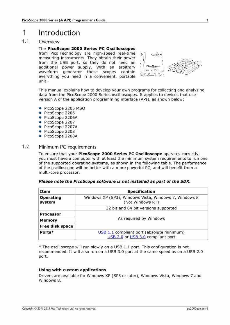
The PicoScope 2000 Series PC Oscilloscopesfrom Pico Technology are high-speed real-timemeasuring instruments. They obtain their powerfrom the USB port, so they do not need anadditional power supply. With an arbitrarywaveform generator these scopes containeverything you need in a convenient, portableunit.
This manual explains how to develop your own programs for collecting and analyzingdata from the PicoScope 2000 Series oscilloscopes. It applies to devices that useversion A of the application programming interface (API), as shown below:
PicoScope 2205 MSOPicoScope 2206PicoScope 2206APicoScope 2207PicoScope 2207APicoScope 2208PicoScope 2208A
1.2 Minimum PC requirementsTo ensure that your PicoScope 2000 Series PC Oscilloscope operates correctly,you must have a computer with at least the minimum system requirements to run oneof the supported operating systems, as shown in the following table. The performanceof the oscilloscope will be better with a more powerful PC, and will benefit from amulti-core processor.
Please note the PicoScope software is not installed as part of the SDK.
Item Specification
Operatingsystem
Windows XP (SP3), Windows Vista, Windows 7, Windows 8(Not Windows RT)
32 bit and 64 bit versions supported
ProcessorAs required by WindowsMemory
Free disk space
Ports* USB 1.1 compliant port (absolute minimum)USB 2.0 or USB 3.0 compliant port
* The oscilloscope will run slowly on a USB 1.1 port. This configuration is notrecommended. It will also run on a USB 3.0 port at the same speed as on a USB 2.0port.
Using with custom applications
Drivers are available for Windows XP (SP3 or later), Windows Vista, Windows 7 andWindows 8.
Introduction2
Copyright © 2011-2013 Pico Technology Ltd. All rights reserved.ps2000apg.en r6
1.3 Legal informationThe material contained in this release is licensed, not sold. Pico Technology Limitedgrants a licence to the person who installs this software, subject to the conditionslisted below.
Access. The licensee agrees to allow access to this software only to persons who havebeen informed of these conditions and agree to abide by them.
Usage. The software in this release is for use only with Pico products or with datacollected using Pico products.
Copyright. Pico Technology Ltd. claims the copyright of, and retains the rights to, allmaterial (software, documents, etc.) contained in this SDK except the exampleprograms. You may copy and distribute the SDK without restriction, as long as you donot remove any Pico Technology copyright statements. The example programs in theSDK may be modified, copied and distributed for the purpose of developing programsto collect data using Pico products.
Liability. Pico Technology and its agents shall not be liable for any loss, damage orinjury, howsoever caused, related to the use of Pico Technology equipment orsoftware, unless excluded by statute.
Fitness for purpose. As no two applications are the same, Pico Technology cannotguarantee that its equipment or software is suitable for a given application. It is yourresponsibility, therefore, to ensure that the product is suitable for your application.
Mission-critical applications. This software is intended for use on a computer thatmay be running other software products. For this reason, one of the conditions of thelicence is that it excludes use in mission-critical applications, for example life supportsystems.
Viruses. This software was continuously monitored for viruses during production, butyou are responsible for virus-checking the software once it is installed.
Support. If you are dissatisfied with the performance of this software, please contactour technical support staff, who will try to fix the problem within a reasonable time. Ifyou are still dissatisfied, please return the product and software to your supplierwithin 28 days of purchase for a full refund.
Upgrades. We provide upgrades, free of charge, from our web site atwww.picotech.com. We reserve the right to charge for updates or replacements sentout on physical media.
Trademarks. Windows is a trademark or registered trademark of MicrosoftCorporation. Pico Technology Limited and PicoScope are internationally registeredtrademarks.
PicoScope 2000 Series (A API) Programmer's Guide 3
Copyright © 2011-2013 Pico Technology Ltd. All rights reserved. ps2000apg.en r6
1.4 Company detailsYou can obtain technical assistance from Pico Technology at the following address:
Address: Pico TechnologyJames HouseColmworth Business ParkSt NeotsCambridgeshirePE19 8YPUnited Kingdom
Phone: +44 (0) 1480 396 395Fax: +44 (0) 1480 396 296
Email:
Technical Support: [email protected]: [email protected]
Web site: www.picotech.com
Programming the 2000 Series Oscilloscopes4
Copyright © 2011-2013 Pico Technology Ltd. All rights reserved.ps2000apg.en r6
2 Programming the 2000 Series Oscilloscopes2.1 About the ps2000a driver
Your application will communicate with an API driver called ps2000a.dll. The driver
exports the ps2000a function definitions in standard C format, but this does not limityou to programming in C. You can use the API with any programming language thatsupports standard C calls.
The API driver depends on a low-level driver called WinUsb.sys. This low-level driver
is installed by the SDK when you plug the oscilloscope into the computer for the firsttime. Your application does not call this driver directly.
2.2 System requirementsGeneral requirements
See Minimum PC requirements.
USB
The ps2000a driver offers four different methods of recording data, all of whichsupport USB 1.1, USB 2.0 and USB 3.0. The fastest transfer rates are achieved usingUSB 2.0 or USB 3.0.
Note: USB 3.0 connections will run at about the same speed as USB 2.0.
2.3 General procedureA typical program for capturing data consists of the following steps: -
Open the scope unit.Set up the input channels with the required voltage ranges and coupling type.Set up triggering.Start capturing data. (See Sampling modes, where programming is discussed inmore detail.)Wait until the scope unit is ready.Stop capturing data.Copy data to a buffer.Close the scope unit.
Numerous sample programs are included in the SDK. These demonstrate how to usethe functions of the driver software in each of the modes available.
2.4 Voltage rangesYou can set a device input channel to any voltage range from ±50 mV to ±20 V withthe ps2000aSetChannel function. Each sample is scaled to 16 bits, and the minimumand maximum values returned to your application are given by ps2000aMinimumValue and ps2000aMaximumValue respectively.
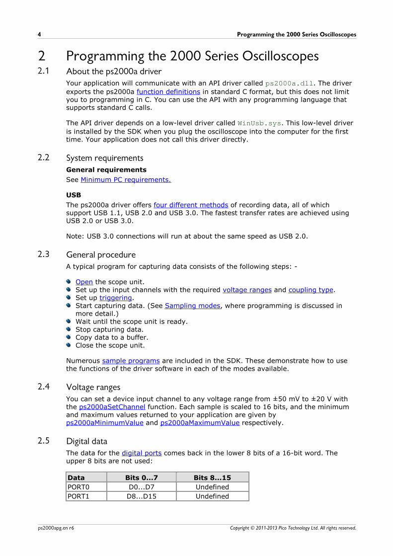
2.5 Digital dataThe data for the digital ports comes back in the lower 8 bits of a 16-bit word. Theupper 8 bits are not used:
Data Bits 0...7 Bits 8...15
PORT0 D0...D7 Undefined
PORT1 D8...D15 Undefined
PicoScope 2000 Series (A API) Programmer's Guide 5
Copyright © 2011-2013 Pico Technology Ltd. All rights reserved. ps2000apg.en r6
2.6 TriggeringThe PicoScope 2000 Series oscilloscopes can either start collecting dataimmediately, or be programmed to wait for a trigger event to occur. In both casesyou need to use the PicoScope 2000 trigger function ps2000aSetSimpleTrigger, whichin turn calls ps2000aSetTriggerChannelConditions,ps2000aSetTriggerChannelDirections and ps2000aSetTriggerChannelProperties (thesecan also be called individually, rather than using ps2000aSetSimpleTrigger). A triggerevent can occur when one of the signal or trigger input channels crosses a thresholdvoltage on either a rising or a falling edge.
2.7 Sampling modesPicoScope 2000 Series oscilloscopes can run in various sampling modes.
Block mode. In this mode, the scope stores data in internal RAM and thentransfers it to the PC. When the data has been collected it is possible to examinethe data, with an optional downsampling factor. The data is lost when a new run isstarted in the same segment, the settings are changed, or the scope is powereddown.
ETS mode. In this mode, it is possible to increase the effective sampling rate ofthe scope when capturing repetitive signals. It is a modified form of block mode.
Rapid block mode. This is a variant of block mode that allows you to capturemore than one waveform at a time with a minimum of delay between captures. Youcan use downsampling in this mode if you wish.
Streaming mode. In this mode, data is passed directly to the PC without beingstored in the scope's internal RAM. This enables long periods of data collection forchart recorder and data-logging applications. Streaming mode supportsdownsampling and triggering, while providing fast streaming at typical rates of 1 to10 MS/s, as specified in the data sheet for your device.
In all sampling modes, the driver returns data asynchronously using a callback. Thisis a call to one of the functions in your own application. When you request data fromthe scope, you pass to the driver a pointer to your callback function. When the driverhas written the data to your buffer, it makes a callback (calls your function) to signalthat the data is ready. The callback function then signals to the application that thedata is available.
Because the callback is called asynchronously from the rest of your application, in aseparate thread, you must ensure that it does not corrupt any global variables while itruns.
For compatibility with programming environments not supporting callback, polling ofthe driver is available in block mode.
2.7.1 Block mode
In block mode, the computer prompts a PicoScope 2000 Series oscilloscope to collecta block of data into its internal memory. When the oscilloscope has collected thewhole block, it signals that it is ready and then transfers the whole block to thecomputer's memory through the USB port.
Programming the 2000 Series Oscilloscopes6
Copyright © 2011-2013 Pico Technology Ltd. All rights reserved.ps2000apg.en r6
Block size. The maximum number of values depends upon the size of theoscilloscope's memory. The memory buffer is shared between the enabledchannels, so if two* channels are enabled, each receives half the memory. Thesefeatures are handled transparently by the driver. The block size also depends onthe number of memory segments in use (see ps2000aMemorySegments).
*The PicoScope 2205 MSO behaves differently. If only the two analog channels oronly the two digital ports are enabled, each receives half the memory. If anycombination of one or two analog channels and one or two digital ports is enabled,each receives a quarter of the memory.
Sampling rate. A PicoScope 2000 Series oscilloscope can sample at a number ofdifferent rates according to the selected timebase and the combination of channelsthat are enabled. See the Timebases section for the specifications that apply toyour scope model.
Setup time. The driver normally performs a number of setup operations, which cantake up to 50 milliseconds, before collecting each block of data. If you need tocollect data with the minimum time interval between blocks, use rapid block modeand avoid calling setup functions between calls to ps2000aRunBlock, ps2000aStopand ps2000aGetValues.
Downsampling. When the data has been collected, you can set an optionaldownsampling factor and examine the data. Downsampling is a process thatreduces the amount of data by combining adjacent samples. It is useful forzooming in and out of the data without having to repeatedly transfer the entirecontents of the scope's buffer to the PC.
Memory segmentation. The scope's internal memory can be divided intosegments so that you can capture several waveforms in succession. Configure thisusing ps2000aMemorySegments.
Data retention. The data is lost when a new run is started in the same segment,the settings are changed, or the scope is powered down.
See Using block mode for programming details.
PicoScope 2000 Series (A API) Programmer's Guide 7
Copyright © 2011-2013 Pico Technology Ltd. All rights reserved. ps2000apg.en r6
2.7.1.1 Using block mode
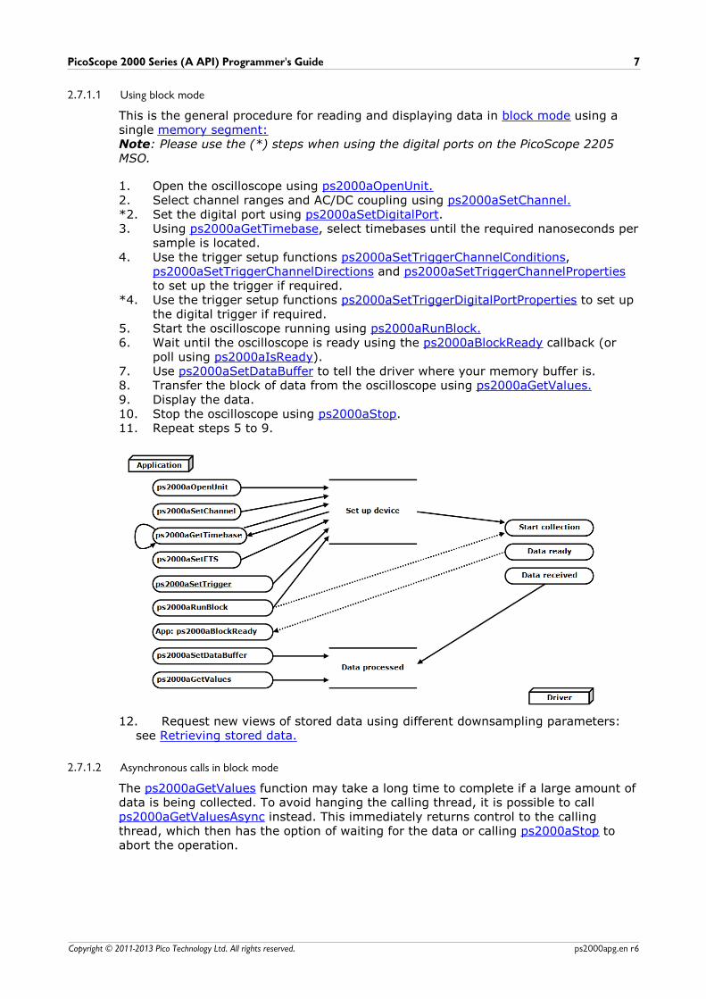
This is the general procedure for reading and displaying data in block mode using asingle memory segment:Note: Please use the (*) steps when using the digital ports on the PicoScope 2205MSO.
1. Open the oscilloscope using ps2000aOpenUnit.2. Select channel ranges and AC/DC coupling using ps2000aSetChannel.*2. Set the digital port using ps2000aSetDigitalPort.3. Using ps2000aGetTimebase, select timebases until the required nanoseconds per
sample is located.4. Use the trigger setup functions ps2000aSetTriggerChannelConditions,
ps2000aSetTriggerChannelDirections and ps2000aSetTriggerChannelPropertiesto set up the trigger if required.
*4. Use the trigger setup functions ps2000aSetTriggerDigitalPortProperties to set upthe digital trigger if required.
5. Start the oscilloscope running using ps2000aRunBlock.6. Wait until the oscilloscope is ready using the ps2000aBlockReady callback (or
poll using ps2000aIsReady).7. Use ps2000aSetDataBuffer to tell the driver where your memory buffer is.8. Transfer the block of data from the oscilloscope using ps2000aGetValues.9. Display the data.10. Stop the oscilloscope using ps2000aStop.11. Repeat steps 5 to 9.
12. Request new views of stored data using different downsampling parameters:see Retrieving stored data.
2.7.1.2 Asynchronous calls in block mode
The ps2000aGetValues function may take a long time to complete if a large amount ofdata is being collected. To avoid hanging the calling thread, it is possible to call ps2000aGetValuesAsync instead. This immediately returns control to the callingthread, which then has the option of waiting for the data or calling ps2000aStop toabort the operation.
Programming the 2000 Series Oscilloscopes8
Copyright © 2011-2013 Pico Technology Ltd. All rights reserved.ps2000apg.en r6
2.7.2 Rapid block mode
In normal block mode, the PicoScope 2000 Series scopes collect one waveform at atime. You start the the device running, wait until all samples are collected by thedevice, and then download the data to the PC or start another run. There is a timeoverhead of tens of milliseconds associated with starting a run, causing a gap betweenwaveforms. When you collect data from the device, there is another minimum timeoverhead which is most noticeable when using a small number of samples.
Rapid block mode allows you to sample several waveforms at a time with theminimum time between waveforms. It reduces the gap from milliseconds to less than2 microseconds (on fastest timebase).
See Using rapid block mode for details.
2.7.2.1 Using rapid block mode
You can use rapid block mode with or without aggregation. With aggregation, youneed to set up two buffers for each channel to receive the minimum and maximumvalues.Note: Please use the * steps when using the digital ports on the PicoScope 2205 MSO.
Without aggregation
1. Open the oscilloscope using ps2000aOpenUnit.2. Select channel ranges and AC/DC coupling using ps2000aSetChannel.*2. Set the digital port using ps2000aSetDigitalPort.3. Using ps2000aGetTimebase, select timebases until the required nanoseconds per
sample is located.4. Use the trigger setup functions ps2000aSetTriggerChannelConditions,
ps2000aSetTriggerChannelDirections and ps2000aSetTriggerChannelPropertiesto set up the trigger if required.
*4. Use the trigger setup functions ps2000aSetTriggerDigitalPortProperties to set upthe digital trigger if required.
5. Set the number of memory segments equal to or greater than the number ofcaptures required using ps2000aMemorySegments. Useps2000aSetNoOfCaptures before each run to specify the number of waveforms tocapture.
6. Start the oscilloscope running using ps2000aRunBlock.7. Wait until the oscilloscope is ready using the ps2000aIsReady or wait on the
callback function.8. Use ps2000aSetDataBuffer to tell the driver where your memory buffers are.9. Transfer the blocks of data from the oscilloscope using ps2000aGetValuesBulk.10. Retrieve the time offset for each data segment using
ps2000aGetValuesTriggerTimeOffsetBulk64.11. Display the data.12. Repeat steps 6 to 11 if necessary.13. Stop the oscilloscope using ps2000aStop.
With aggregation
To use rapid block mode with aggregation, follow steps 1 to 7 above and then proceedas follows:
8a. Call ps2000aSetDataBuffer or (ps2000aSetDataBuffers) to set up one pair ofbuffers for every waveform segment required.
9a. Call ps2000aGetValuesBulk for each pair of buffers.10a. Retrieve the time offset for each data segment using
ps2000aGetValuesTriggerTimeOffsetBulk64.
Continue from step 11.
PicoScope 2000 Series (A API) Programmer's Guide 9
Copyright © 2011-2013 Pico Technology Ltd. All rights reserved. ps2000apg.en r6
2.7.2.2 Rapid block mode example 1: no aggregation
#define MAX_SAMPLES 1000
Set up the device up as usual.
Open the deviceChannelsTriggerNumber of memory segments (this should be equal or more than the no of capturesrequired)
// set the number of waveforms to 32ps2000aSetNoOfCaptures (handle, 32);
pParameter = false;ps2000aRunBlock(
handle,0, // noOfPreTriggerSamplesMAX_SAMPLES, // noOfPostTriggerSamples1, // timebase to be used1, &timeIndisposedMs,1, // segment indexlpReady,&pParameter
);
Comment: these variables have been set as an example and can be any valid value.pParameter will be set true by your callback function lpReady.
while (!pParameter) Sleep (0);
for (int i = 0; i < 10; i++){
for (int c = PS2000A_CHANNEL_A; c <= PS2000A_CHANNEL_B; c++){
ps2000aSetDataBuffer(
handle,c,&buffer[c][i],MAX_SAMPLES,i
PS2000A_RATIO_MODE_NONE);
}}
Comments: buffer has been created as a two-dimensional array of pointers to shorts,which will contain 1000 samples as defined by MAX_SAMPLES. There are only 10
buffers set, but it is possible to set up to the number of captures you have requested.
Programming the 2000 Series Oscilloscopes10
Copyright © 2011-2013 Pico Technology Ltd. All rights reserved.ps2000apg.en r6
ps2000aGetValuesBulk(
handle,&noOfSamples, // set to MAX_SAMPLES on entering thefunction10, // fromSegmentIndex19, // toSegmentIndex1, // downsampling ratioPS2000A_RATIO_MODE_NONE, // downsampling ratio modeoverflow // an array of size 10 shorts
)
Comments: the number of samples could be up to noOfPreTriggerSamples +noOfPostTriggerSamples, the values set in ps2000aRunBlock. The samples are
always returned from the first sample taken, unlike the ps2000aGetValues function
which allows the sample index to be set. The above segments start at 10 and finish at19 inclusive. It is possible for the fromSegmentIndex to wrap around to the
toSegmentIndex, by setting the fromSegmentIndex to 28 and the
toSegmentIndex to 7.
ps2000aGetValuesTriggerTimeOffsetBulk64(
handle,times,timeUnits,10,19
)
Comments: the above segments start at 10 and finish at 19 inclusive. It is possible forthe fromSegmentIndex to wrap around to the toSegmentIndex, if the
fromSegmentIndex is set to 28 and the toSegmentIndex to 7.
PicoScope 2000 Series (A API) Programmer's Guide 11
Copyright © 2011-2013 Pico Technology Ltd. All rights reserved. ps2000apg.en r6
2.7.2.3 Rapid block mode example 2: using aggregation
#define MAX_SAMPLES 1000
Set up the device up as usual.
Open the deviceChannelsTriggerNumber of memory segments (this should be equal or more than the number ofcaptures required)
// set the number of waveforms to 32ps2000aSetNoOfCaptures (handle, 32);
pParameter = false;ps2000aRunBlock(
handle,0, //noOfPreTriggerSamples,MAX_SAMPLES, // noOfPostTriggerSamples,1, // timebase to be used,1, &timeIndisposedMs,1, // SegmentIndexlpReady,&pParameter
);
Comments: the set-up for running the device is exactly the same whether or notaggregation will be used when you retrieve the samples.
for (int segment = 10; segment < 20; segment++){for (int c = PS2000A_CHANNEL_A; c <= PS2000A_CHANNEL_D; c++){
ps2000aSetDataBuffers(
handle,c,&bufferMax[c],&bufferMin[c]MAX_SAMPLESSegment,PS2000A_RATIO_MODE_AGGREGATE
);}
Comments: since only one waveform will be retrieved at a time, you only need to setup one pair of buffers; one for the maximum samples and one for the minimumsamples. Again, the buffer sizes are 1000 (MAX_SAMPLES) samples.
Programming the 2000 Series Oscilloscopes12
Copyright © 2011-2013 Pico Technology Ltd. All rights reserved.ps2000apg.en r6
ps2000aGetValues(
handle,0,&noOfSamples, // set to MAX_SAMPLES on entering10, &downSampleRatioMode, //set to RATIO_MODE_AGGREGATEindex,overflow
);
ps2000aGetTriggerTimeOffset64 (
handle,&time,&timeUnits,index
)}
Comments: each waveform is retrieved one at a time from the driver with anaggregation of 10.
2.7.3 ETS (Equivalent Time Sampling)
ETS is a way of increasing the effective sampling rate of the scope when capturingrepetitive signals. It is a modified form of block mode, and is controlled by theps2000a set of trigger functions and the ps2000aSetEts function.
Overview. ETS works by capturing several cycles of a repetitive waveform, thencombining them to produce a composite waveform that has a higher effectivesampling rate than the individual captures. The scope hardware accuratelymeasures the delay, which is a small fraction of a single sampling interval, betweeneach trigger event and the subsequent sample. The driver then shifts each captureslightly in time and overlays them so that the trigger points are exactly lined up.The result is a larger set of samples spaced by a small fraction of the originalsampling interval. The maximum effective sampling rates that can be achieved withthis method are listed in the User's Guide for the scope device. Other scopes do notcontain special ETS hardware, so the composite waveform is created by software.
Trigger stability. Because of the high sensitivity of ETS mode to small timedifferences, the trigger must be set up to provide a stable waveform that varies aslittle as possible from one capture to the next.
Callback. ETS mode calls the ps2000aBlockReady callback function when a newwaveform is ready for collection. The ps2000aGetValues function needs to be calledfor the waveform to be retrieved.
Applicability Available in block mode only.Not suitable for one-shot (non-repetitive) signals.Aggregation is not supported.Edge-triggering only.Auto trigger delay (autoTriggerMilliseconds) is ignored.
Cannot be used when MSO digital ports are enabled.
PicoScope 2000 Series (A API) Programmer's Guide 13
Copyright © 2011-2013 Pico Technology Ltd. All rights reserved. ps2000apg.en r6
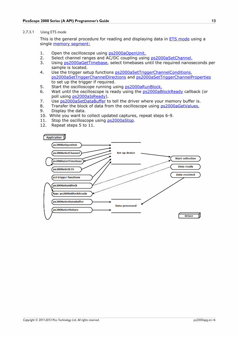
2.7.3.1 Using ETS mode
This is the general procedure for reading and displaying data in ETS mode using asingle memory segment:
1. Open the oscilloscope using ps2000aOpenUnit.2. Select channel ranges and AC/DC coupling using ps2000aSetChannel.3. Using ps2000aGetTimebase, select timebases until the required nanoseconds per
sample is located.4. Use the trigger setup functions ps2000aSetTriggerChannelConditions,
ps2000aSetTriggerChannelDirections and ps2000aSetTriggerChannelPropertiesto set up the trigger if required.
5. Start the oscilloscope running using ps2000aRunBlock.6. Wait until the oscilloscope is ready using the ps2000aBlockReady callback (or
poll using ps2000aIsReady).7. Use ps2000aSetDataBuffer to tell the driver where your memory buffer is.8. Transfer the block of data from the oscilloscope using ps2000aGetValues.9. Display the data.10. While you want to collect updated captures, repeat steps 6-9.11. Stop the oscilloscope using ps2000aStop.12. Repeat steps 5 to 11.
Programming the 2000 Series Oscilloscopes14
Copyright © 2011-2013 Pico Technology Ltd. All rights reserved.ps2000apg.en r6
2.7.4 Streaming mode
Streaming mode, unlike block mode, can capture data without gaps between blocks.Streaming mode supports downsampling and triggering, while providing faststreaming. This makes it suitable for high-speed data acquisition, allowing you tocapture long data sets limited only by the computer's memory.
Aggregation. The driver returns aggregated readings while the device isstreaming. If aggregation is set to 1, only one buffer is used per channel. Whenaggregation is set above 1, two buffers (maximum and minimum) per channel areused.
Memory segmentation. The memory can be divided into segments to reduce thelatency of data transfers to the PC. However, this increases the risk of losing data ifthe PC cannot keep up with the device's sampling rate.
See Using streaming mode for programming details.
PicoScope 2000 Series (A API) Programmer's Guide 15
Copyright © 2011-2013 Pico Technology Ltd. All rights reserved. ps2000apg.en r6
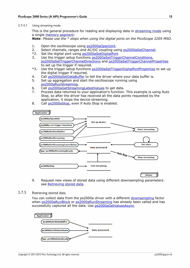
2.7.4.1 Using streaming mode
This is the general procedure for reading and displaying data in streaming mode usinga single memory segment:Note: Please use the * steps when using the digital ports on the PicoScope 2205 MSO.
1. Open the oscilloscope using ps2000aOpenUnit.2. Select channels, ranges and AC/DC coupling using ps2000aSetChannel.*2. Set the digital port using ps2000aSetDigitalPort.3. Use the trigger setup functions ps2000aSetTriggerChannelConditions,
ps2000aSetTriggerChannelDirections and ps2000aSetTriggerChannelPropertiesto set up the trigger if required.
*3. Use the trigger setup functions ps2000aSetTriggerDigitalPortProperties to set upthe digital trigger if required.
4. Call ps2000aSetDataBuffer to tell the driver where your data buffer is.5. Set up aggregation and start the oscilloscope running using
ps2000aRunStreaming.6. Call ps2000aGetStreamingLatestValues to get data.7. Process data returned to your application's function. This example is using Auto
Stop, so after the driver has received all the data points requested by theapplication, it stops the device streaming.
8. Call ps2000aStop, even if Auto Stop is enabled.
9. Request new views of stored data using different downsampling parameters:see Retrieving stored data.
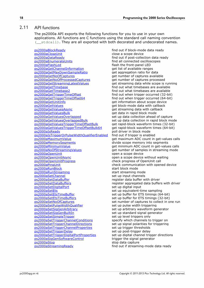
2.7.5 Retrieving stored data
You can collect data from the ps2000a driver with a different downsampling factorwhen ps2000aRunBlock or ps2000aRunStreaming has already been called and hassuccessfully captured all the data. Use ps2000aGetValuesAsync.
Programming the 2000 Series Oscilloscopes16
Copyright © 2011-2013 Pico Technology Ltd. All rights reserved.ps2000apg.en r6
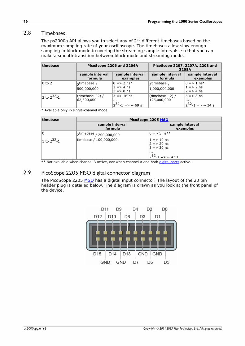
2.8 Timebases
The ps2000a API allows you to select any of 232 different timebases based on themaximum sampling rate of your oscilloscope. The timebases allow slow enoughsampling in block mode to overlap the streaming sample intervals, so that you canmake a smooth transition between block mode and streaming mode.
timebase PicoScope 2206 and 2206A PicoScope 2207, 2207A, 2208 and2208A
sample interval formula
sample interval examples
sample interval formula
sample interval examples
0 to 2 2timebase /500,000,000
0 => 2 ns*1 => 4 ns2 => 8 ns
2timebase /1,000,000,000
0 => 1 ns*1 => 2 ns2 => 4 ns
3 to 232-1 (timebase - 2) /62,500,000
3 => 16 ns...
232-1 => ~ 69 s
(timebase - 2) /125,000,000
3 => 8 ns...
232-1 => ~ 34 s
* Available only in single-channel mode.
timebase PicoScope 2205 MSO
sample interval formula
sample interval examples
0 2timebase / 200,000,000 0 => 5 ns**
1 to 232-1 timebase / 100,000,000 1 => 10 ns2 => 20 ns3 => 30 ns...
232-1 => ~ 43 s
** Not available when channel B active, nor when channel A and both digital ports active.
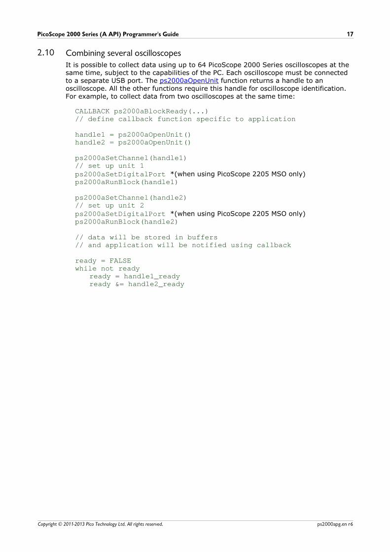
2.9 PicoScope 2205 MSO digital connector diagramThe PicoScope 2205 MSO has a digital input connector. The layout of the 20 pinheader plug is detailed below. The diagram is drawn as you look at the front panel ofthe device.
PicoScope 2000 Series (A API) Programmer's Guide 17
Copyright © 2011-2013 Pico Technology Ltd. All rights reserved. ps2000apg.en r6
2.10 Combining several oscilloscopesIt is possible to collect data using up to 64 PicoScope 2000 Series oscilloscopes at thesame time, subject to the capabilities of the PC. Each oscilloscope must be connectedto a separate USB port. The ps2000aOpenUnit function returns a handle to anoscilloscope. All the other functions require this handle for oscilloscope identification.For example, to collect data from two oscilloscopes at the same time:
CALLBACK ps2000aBlockReady(...)// define callback function specific to application
handle1 = ps2000aOpenUnit()handle2 = ps2000aOpenUnit()
ps2000aSetChannel(handle1)// set up unit 1ps2000aSetDigitalPort *(when using PicoScope 2205 MSO only)ps2000aRunBlock(handle1)
ps2000aSetChannel(handle2)// set up unit 2ps2000aSetDigitalPort *(when using PicoScope 2205 MSO only)ps2000aRunBlock(handle2)
// data will be stored in buffers // and application will be notified using callback
ready = FALSEwhile not ready
ready = handle1_readyready &= handle2_ready
Programming the 2000 Series Oscilloscopes18
Copyright © 2011-2013 Pico Technology Ltd. All rights reserved.ps2000apg.en r6
2.11 API functionsThe ps2000a API exports the following functions for you to use in your ownapplications. All functions are C functions using the standard call naming convention(__stdcall). They are all exported with both decorated and undecorated names.
ps2000aBlockReady find out if block-mode data readyps2000aCloseUnit close a scope deviceps2000aDataReady find out if post-collection data readyps2000aEnumerateUnits find all connected oscilloscopesps2000aFlashLed flash the front-panel LEDps2000aGetChannelInformation get list of available rangesps2000aGetMaxDownSampleRatio get aggregation ratio for dataps2000aGetNoOfCaptures get number of captures availableps2000aGetNoOfProcessedCaptures get number of captures processedps2000aGetStreamingLatestValues get streaming data while scope is runningps2000aGetTimebase find out what timebases are availableps2000aGetTimebase2 find out what timebases are availableps2000aGetTriggerTimeOffset find out when trigger occurred (32-bit)ps2000aGetTriggerTimeOffset64 find out when trigger occurred (64-bit)ps2000aGetUnitInfo get information about scope deviceps2000aGetValues get block-mode data with callbackps2000aGetValuesAsync get streaming data with callbackps2000aGetValuesBulk get data in rapid block modeps2000aGetValuesOverlapped set up data collection ahead of captureps2000aGetValuesOverlappedBulk set up data collection in rapid block modeps2000aGetValuesTriggerTimeOffsetBulk get rapid-block waveform times (32-bit)ps2000aGetValuesTriggerTimeOffsetBulk64 get rapid-block waveform times (64-bit)ps2000aIsReady poll driver in block modeps2000aIsTriggerOrPulseWidthQualifierEnabled find out if trigger is enabledps2000aMaximumValue get maximum ADC count in get-values callsps2000aMemorySegments divide scope memory into segmentsps2000aMinimumValue get minimum ADC count in get-values callsps2000aNoOfStreamingValues get number of samples in streaming modeps2000aOpenUnit open a scope deviceps2000aOpenUnitAsync open a scope device without waitingps2000aOpenUnitProgress check progress of OpenUnit callps2000aPingUnit check communication with opened deviceps2000aRunBlock start block modeps2000aRunStreaming start streaming modeps2000aSetChannel set up input channelsps2000aSetDataBuffer register data buffer with driverps2000aSetDataBuffers register aggregated data buffers with driverps2000aSetDigitalPort set up digital inputps2000aSetEts set up equivalent-time samplingps2000aSetEtsTimeBuffer set up buffer for ETS timings (64-bit)ps2000aSetEtsTimeBuffers set up buffer for ETS timings (32-bit)ps2000aSetNoOfCaptures set number of captures to collect in one runps2000aSetPulseWidthQualifier set up pulse width triggeringps2000aSetSigGenArbitrary set up arbitrary waveform generatorps2000aSetSigGenBuiltIn set up standard signal generatorps2000aSetSimpleTrigger set up level triggers onlyps2000aSetTriggerChannelConditions specify which channels to trigger onps2000aSetTriggerChannelDirections set up signal polarities for triggeringps2000aSetTriggerChannelProperties set up trigger thresholdsps2000aSetTriggerDelay set up post-trigger delayps2000aSetTriggerDigitalPortProperties set up digital channel trigger directionsps2000aSigGenSoftwareControl trigger the signal generatorps2000aStop stop data captureps2000aStreamingReady find out if streaming-mode data ready
PicoScope 2000 Series (A API) Programmer's Guide 19
Copyright © 2011-2013 Pico Technology Ltd. All rights reserved. ps2000apg.en r6
2.11.1 ps2000aBlockReadytypedef void (CALLBACK *ps2000aBlockReady) (
short handle,PICO_STATUS status,void * pParameter
)
This callback function is part of your application. You register it with the ps2000adriver using ps2000aRunBlock, and the driver calls it back when block-mode data isready. You can then download the data using the ps2000aGetValues function.
Applicability Block mode only
Arguments handle, the handle of the device returning the samples.
status, indicates whether an error occurred during collection of
the data.
* pParameter, a void pointer passed from ps2000aRunBlock. Your
callback function can write to this location to send any data, such asa status flag, back to your application.
Returns nothing
Programming the 2000 Series Oscilloscopes20
Copyright © 2011-2013 Pico Technology Ltd. All rights reserved.ps2000apg.en r6
2.11.2 ps2000aCloseUnitPICO_STATUS ps2000aCloseUnit (
short handle)
This function shuts down an oscilloscope.
Applicability All modes
Arguments handle, the handle, returned by ps2000aOpenUnit, of the scope
device to be closed.
Returns PICO_OKPICO_HANDLE_INVALIDPICO_USER_CALLBACKPICO_DRIVER_FUNCTION
PicoScope 2000 Series (A API) Programmer's Guide 21
Copyright © 2011-2013 Pico Technology Ltd. All rights reserved. ps2000apg.en r6
2.11.3 ps2000aDataReadytypedef void (__stdcall *ps2000aDataReady) (
short handle,PICO_STATUS status,unsigned long noOfSamples,short overflow,void * pParameter
)
This is a callback function that you write to collect data from the driver. You supply apointer to the function when you call ps2000aGetValuesAsync, and the driver callsyour function back when the data is ready.
Applicability All modes
Arguments handle, the handle of the device returning the samples.
status, a PICO_STATUS code returned by the driver.
noOfSamples, the number of samples collected.
overflow, a set of flags that indicates whether an overvoltage has
occurred and on which channels. It is a bit field with bit 0representing Channel A.
* pParameter, a void pointer passed from
ps2000aGetValuesAsync. The callback function can write to thislocation to send any data, such as a status flag, back to theapplication. The data type is defined by the application programmer.
Returns nothing
Programming the 2000 Series Oscilloscopes22
Copyright © 2011-2013 Pico Technology Ltd. All rights reserved.ps2000apg.en r6
2.11.4 ps2000aEnumerateUnitsPICO_STATUS ps2000aEnumerateUnits (
short * count,char * serials,short * serialLth
)
This function counts the number of PicoScope 2000(A) Series units connected to thecomputer, and returns a list of serial numbers as a string.
Applicability All modes
Arguments * count, on exit, the number of ps2000a units found.
* serials, on exit, a list of serial numbers separated by commas
and terminated by a final null.
Example: AQ005/139,VDR61/356,ZOR14/107
Can be NULL on entry if serial numbers are not required.
* serialLth, on entry, the length of the char buffer pointed to by
serials; on exit, the length of the string written to serials.
Returns PICO_OKPICO_BUSYPICO_NULL_PARAMETERPICO_FW_FAILPICO_CONFIG_FAILPICO_MEMORY_FAILPICO_CONFIG_FAIL_AWGPICO_INITIALISE_FPGA
PicoScope 2000 Series (A API) Programmer's Guide 23
Copyright © 2011-2013 Pico Technology Ltd. All rights reserved. ps2000apg.en r6
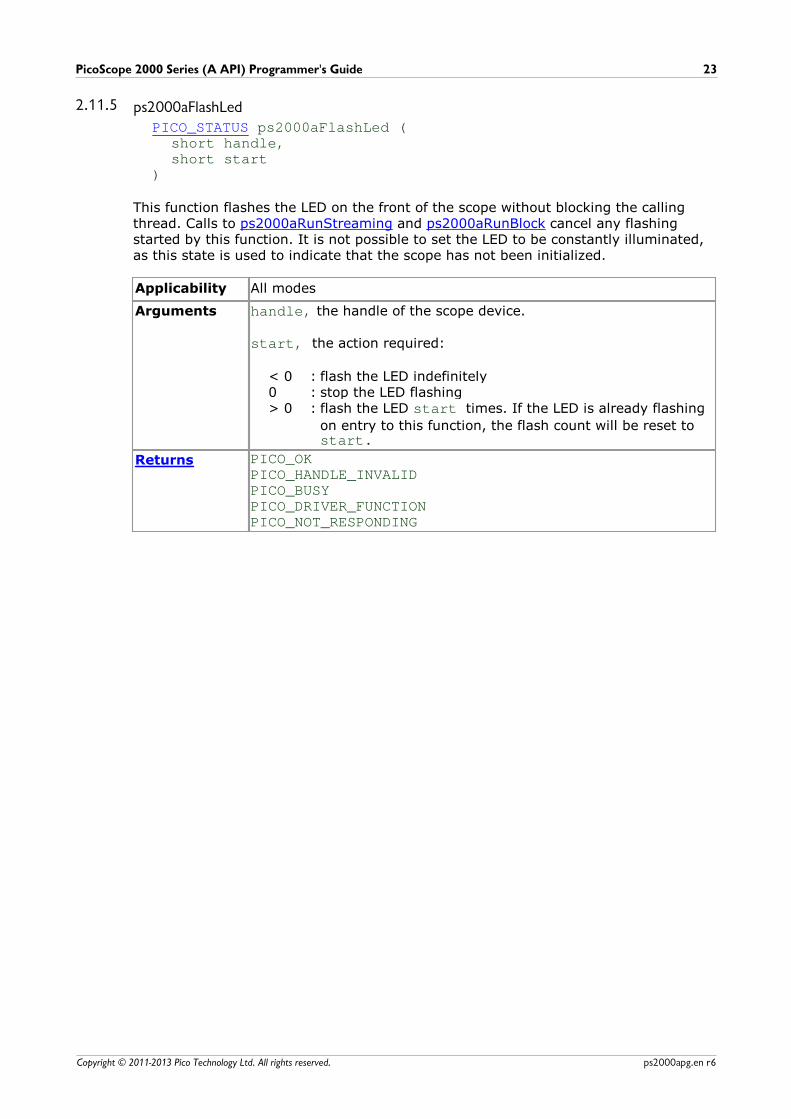
2.11.5 ps2000aFlashLedPICO_STATUS ps2000aFlashLed (
short handle,short start
)
This function flashes the LED on the front of the scope without blocking the callingthread. Calls to ps2000aRunStreaming and ps2000aRunBlock cancel any flashingstarted by this function. It is not possible to set the LED to be constantly illuminated,as this state is used to indicate that the scope has not been initialized.
Applicability All modes
Arguments handle, the handle of the scope device.
start, the action required:
< 0 : flash the LED indefinitely0 : stop the LED flashing> 0 : flash the LED start times. If the LED is already flashing
on entry to this function, the flash count will be reset to start.
Returns PICO_OK PICO_HANDLE_INVALIDPICO_BUSYPICO_DRIVER_FUNCTIONPICO_NOT_RESPONDING
Programming the 2000 Series Oscilloscopes24
Copyright © 2011-2013 Pico Technology Ltd. All rights reserved.ps2000apg.en r6
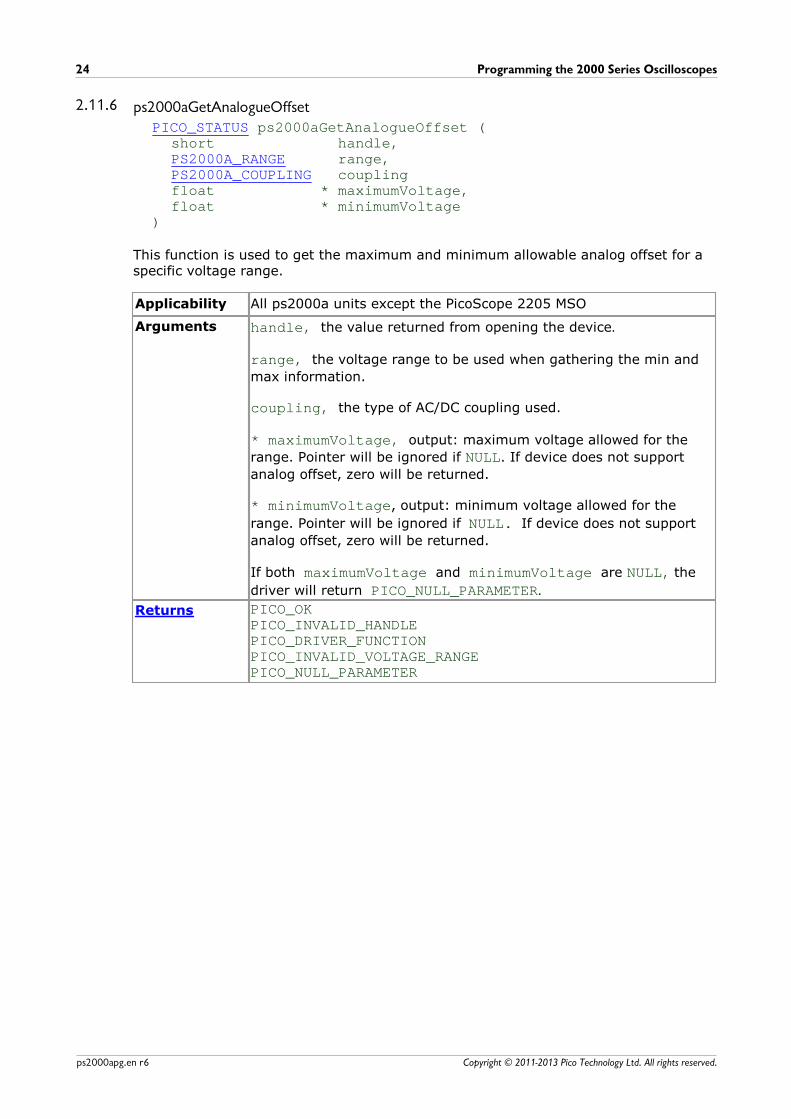
2.11.6 ps2000aGetAnalogueOffsetPICO_STATUS ps2000aGetAnalogueOffset (
short handle,PS2000A_RANGE range,PS2000A_COUPLING couplingfloat * maximumVoltage,float * minimumVoltage
)
This function is used to get the maximum and minimum allowable analog offset for aspecific voltage range.
Applicability All ps2000a units except the PicoScope 2205 MSO
Arguments handle, the value returned from opening the device.
range, the voltage range to be used when gathering the min and
max information.
coupling, the type of AC/DC coupling used.
* maximumVoltage, output: maximum voltage allowed for the
range. Pointer will be ignored if NULL. If device does not support
analog offset, zero will be returned.
* minimumVoltage, output: minimum voltage allowed for the
range. Pointer will be ignored if NULL. If device does not support
analog offset, zero will be returned.
If both maximumVoltage and minimumVoltage are NULL, the
driver will return PICO_NULL_PARAMETER.
Returns PICO_OK PICO_INVALID_HANDLEPICO_DRIVER_FUNCTIONPICO_INVALID_VOLTAGE_RANGEPICO_NULL_PARAMETER
PicoScope 2000 Series (A API) Programmer's Guide 25
Copyright © 2011-2013 Pico Technology Ltd. All rights reserved. ps2000apg.en r6
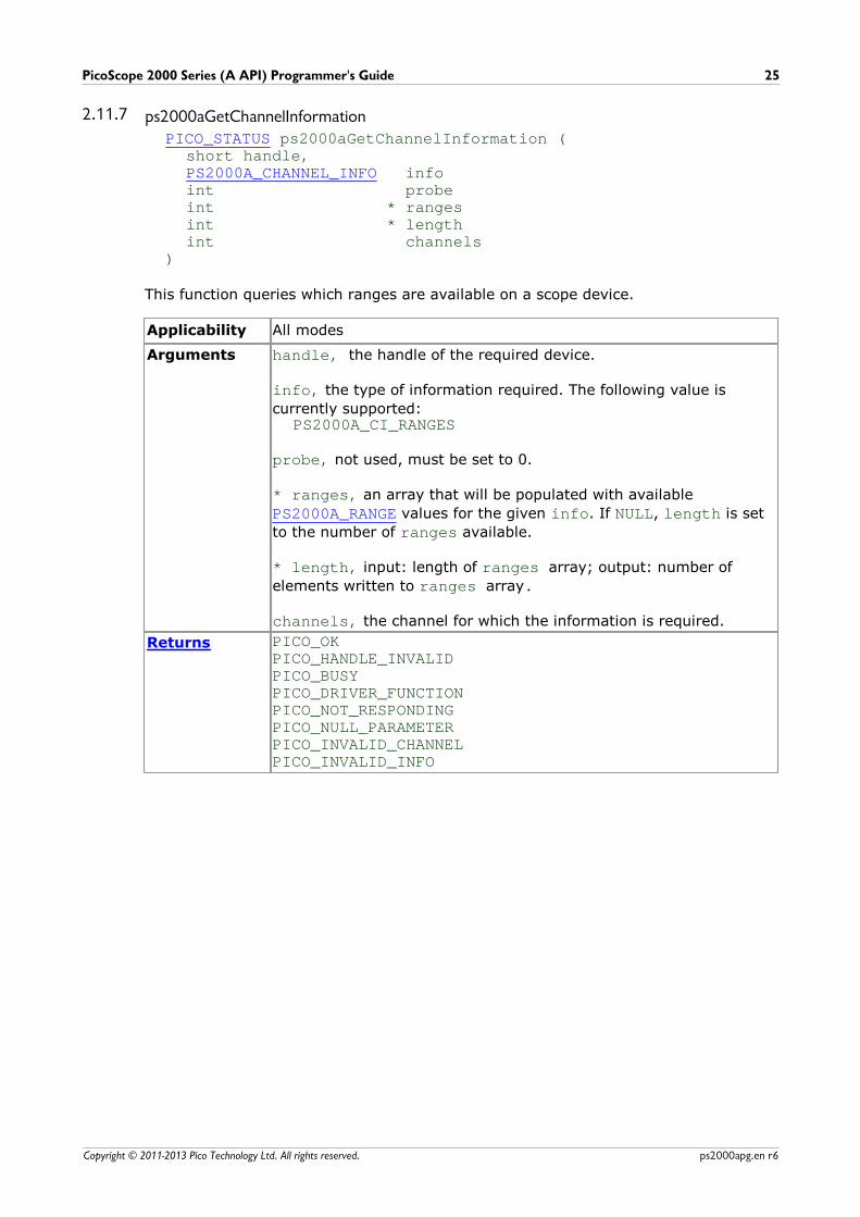
2.11.7 ps2000aGetChannelInformationPICO_STATUS ps2000aGetChannelInformation (
short handle,PS2000A_CHANNEL_INFO infoint probeint * rangesint * lengthint channels
)
This function queries which ranges are available on a scope device.
Applicability All modes
Arguments handle, the handle of the required device.
info, the type of information required. The following value is
currently supported:PS2000A_CI_RANGES
probe, not used, must be set to 0.
* ranges, an array that will be populated with available
PS2000A_RANGE values for the given info. If NULL, length is set
to the number of ranges available.
* length, input: length of ranges array; output: number of
elements written to ranges array.
channels, the channel for which the information is required.
Returns PICO_OK PICO_HANDLE_INVALIDPICO_BUSYPICO_DRIVER_FUNCTIONPICO_NOT_RESPONDINGPICO_NULL_PARAMETERPICO_INVALID_CHANNELPICO_INVALID_INFO
Programming the 2000 Series Oscilloscopes26
Copyright © 2011-2013 Pico Technology Ltd. All rights reserved.ps2000apg.en r6
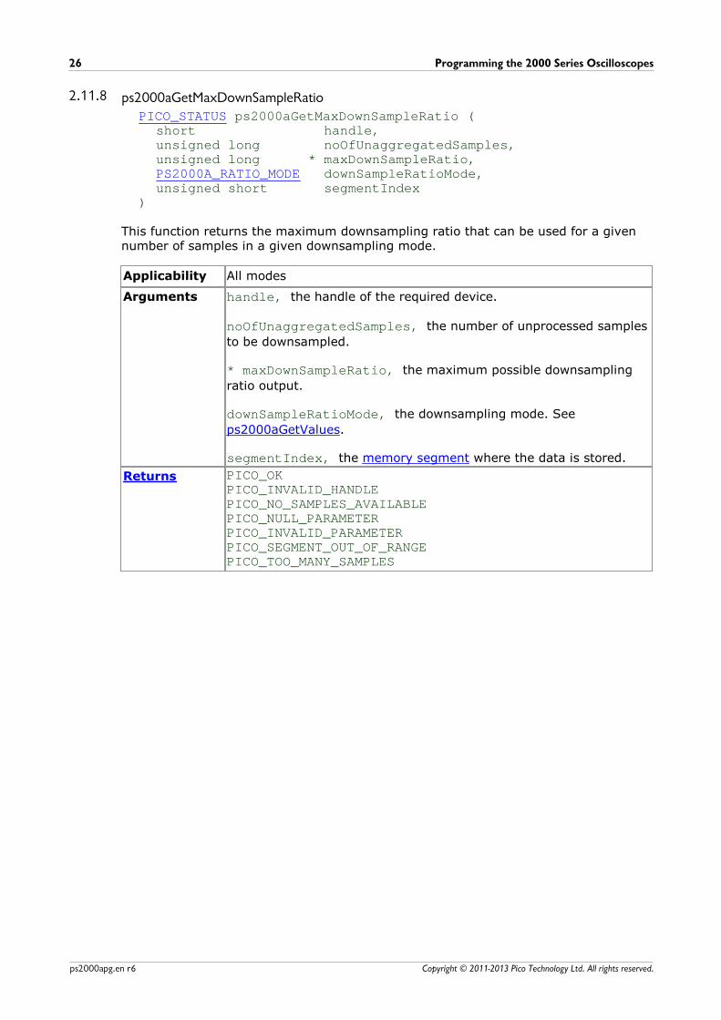
2.11.8 ps2000aGetMaxDownSampleRatioPICO_STATUS ps2000aGetMaxDownSampleRatio (
short handle,unsigned long noOfUnaggregatedSamples,unsigned long * maxDownSampleRatio, PS2000A_RATIO_MODE downSampleRatioMode,unsigned short segmentIndex
)
This function returns the maximum downsampling ratio that can be used for a givennumber of samples in a given downsampling mode.
Applicability All modes
Arguments handle, the handle of the required device.
noOfUnaggregatedSamples, the number of unprocessed samples
to be downsampled.
* maxDownSampleRatio, the maximum possible downsampling
ratio output.
downSampleRatioMode, the downsampling mode. See
ps2000aGetValues.
segmentIndex, the memory segment where the data is stored.
Returns PICO_OKPICO_INVALID_HANDLEPICO_NO_SAMPLES_AVAILABLEPICO_NULL_PARAMETERPICO_INVALID_PARAMETERPICO_SEGMENT_OUT_OF_RANGEPICO_TOO_MANY_SAMPLES
PicoScope 2000 Series (A API) Programmer's Guide 27
Copyright © 2011-2013 Pico Technology Ltd. All rights reserved. ps2000apg.en r6
2.11.9 ps2000aGetMaxSegmentsPICO_STATUS ps2000aGetMaxSegments (
short handle,unsigned short * maxsegments
)
This function returns the maximum number of segments allowed for the openedvariant. Refer to ps2000aMemorySegments for specific figures.
Applicability All modes
Arguments handle, the value returned from opening the device.
* maxsegments, output: maximum number of segments allowed.
Returns PICO_OK PICO_INVALID_HANDLEPICO_DRIVER_FUNCTIONPICO_NULL_PARAMETER
Programming the 2000 Series Oscilloscopes28
Copyright © 2011-2013 Pico Technology Ltd. All rights reserved.ps2000apg.en r6
2.11.10 ps2000aGetNoOfCapturesPICO_STATUS ps2000aGetNoOfCaptures (
short handle, unsigned long * nCaptures
)
This function finds out how many captures are available in rapid block mode after ps2000aRunBlock has been called when either the collection completed or the
collection of waveforms was interrupted by calling ps2000aStop. The returned value
(nCaptures) can then be used to iterate through the number of segments using
ps2000aGetValues, or in a single call to ps2000aGetValuesBulk where it is used
to calculate the toSegmentIndex parameter.
Applicability rapid block mode
Arguments handle, handle of the required device.
* nCaptures, output: the number of available captures that has
been collected from calling ps2000aRunBlock.
Returns PICO_OKPICO_DRIVER_FUNCTIONPICO_INVALID_HANDLEPICO_NOT_RESPONDINGPICO_NO_SAMPLES_AVAILABLEPICO_NULL_PARAMETERPICO_INVALID_PARAMETERPICO_SEGMENT_OUT_OF_RANGEPICO_TOO_MANY_SAMPLES
PicoScope 2000 Series (A API) Programmer's Guide 29
Copyright © 2011-2013 Pico Technology Ltd. All rights reserved. ps2000apg.en r6
2.11.11 ps2000aGetNoOfProcessedCapturesPICO_STATUS ps2000aGetNoOfProcessedCaptures (
short handle, unsigned long * nCaptures
)
This function finds out how many captures in rapid block mode have been processedafter ps2000aRunBlock has been called when either the collection completed or the
collection of waveforms was interrupted by calling ps2000aStop. The returned value
(nCaptures) can then be used to iterate through the number of segments using
ps2000aGetValues, or in a single call to ps2000aGetValuesBulk where it is used
to calculate the toSegmentIndex parameter.
Applicability in rapid block mode
Arguments handle, handle of the required device.
* nCaptures, output: the number of available captures that has
been collected from calling ps2000aRunBlock.
Returns PICO_OKPICO_DRIVER_FUNCTIONPICO_INVALID_HANDLEPICO_NO_SAMPLES_AVAILABLEPICO_NULL_PARAMETERPICO_INVALID_PARAMETERPICO_SEGMENT_OUT_OF_RANGEPICO_TOO_MANY_SAMPLES
Programming the 2000 Series Oscilloscopes30
Copyright © 2011-2013 Pico Technology Ltd. All rights reserved.ps2000apg.en r6
2.11.12 ps2000aGetStreamingLatestValuesPICO_STATUS ps2000aGetStreamingLatestValues (
short handle,ps2000aStreamingReady lpPs2000AReady,void * pParameter
)
This function instructs the driver to return the next block of values to your ps2000aStreamingReady callback function. You must have previously calledps2000aRunStreaming beforehand to set up streaming.
Applicability Streaming mode only
Arguments handle, the handle of the required device.
lpPs2000AReady, a pointer to your ps2000aStreamingReady
callback function.
* pParameter, a void pointer that will be passed to the
ps2000aStreamingReady callback function. The callback functionmay optionally use this pointer to return information to theapplication.
Returns PICO_OKPICO_INVALID_HANDLEPICO_NO_SAMPLES_AVAILABLEPICO_INVALID_CALLPICO_BUSYPICO_NOT_RESPONDINGPICO_DRIVER_FUNCTION
PicoScope 2000 Series (A API) Programmer's Guide 31
Copyright © 2011-2013 Pico Technology Ltd. All rights reserved. ps2000apg.en r6
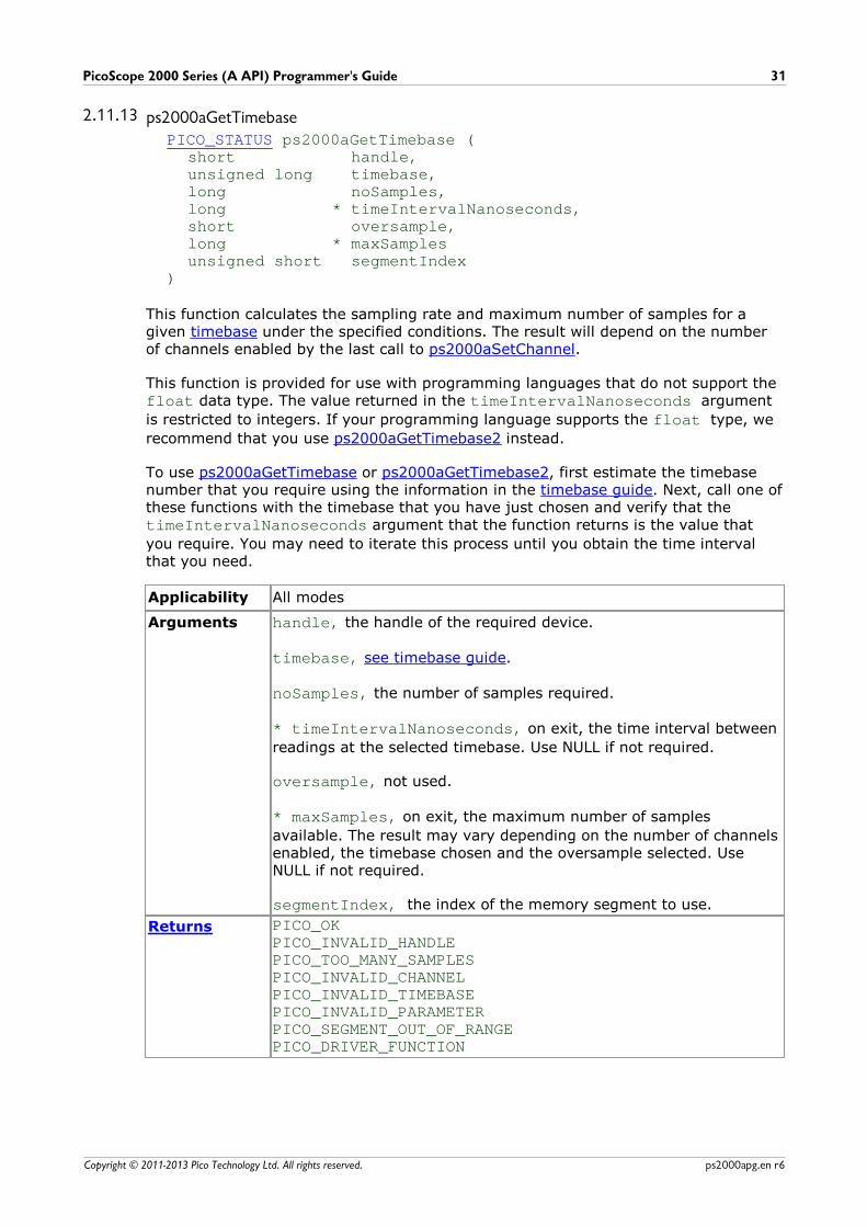
2.11.13 ps2000aGetTimebasePICO_STATUS ps2000aGetTimebase (
short handle,unsigned long timebase,long noSamples,long * timeIntervalNanoseconds,short oversample,long * maxSamplesunsigned short segmentIndex
)
This function calculates the sampling rate and maximum number of samples for agiven timebase under the specified conditions. The result will depend on the numberof channels enabled by the last call to ps2000aSetChannel.
This function is provided for use with programming languages that do not support the float data type. The value returned in the timeIntervalNanoseconds argument
is restricted to integers. If your programming language supports the float type, we
recommend that you use ps2000aGetTimebase2 instead.
To use ps2000aGetTimebase or ps2000aGetTimebase2, first estimate the timebasenumber that you require using the information in the timebase guide. Next, call one ofthese functions with the timebase that you have just chosen and verify that the timeIntervalNanoseconds argument that the function returns is the value that
you require. You may need to iterate this process until you obtain the time intervalthat you need.
Applicability All modes
Arguments handle, the handle of the required device.
timebase, see timebase guide.
noSamples, the number of samples required.
* timeIntervalNanoseconds, on exit, the time interval between
readings at the selected timebase. Use NULL if not required.
oversample, not used.
* maxSamples, on exit, the maximum number of samples
available. The result may vary depending on the number of channelsenabled, the timebase chosen and the oversample selected. UseNULL if not required.
segmentIndex, the index of the memory segment to use.
Returns PICO_OKPICO_INVALID_HANDLEPICO_TOO_MANY_SAMPLESPICO_INVALID_CHANNELPICO_INVALID_TIMEBASEPICO_INVALID_PARAMETERPICO_SEGMENT_OUT_OF_RANGEPICO_DRIVER_FUNCTION
Programming the 2000 Series Oscilloscopes32
Copyright © 2011-2013 Pico Technology Ltd. All rights reserved.ps2000apg.en r6
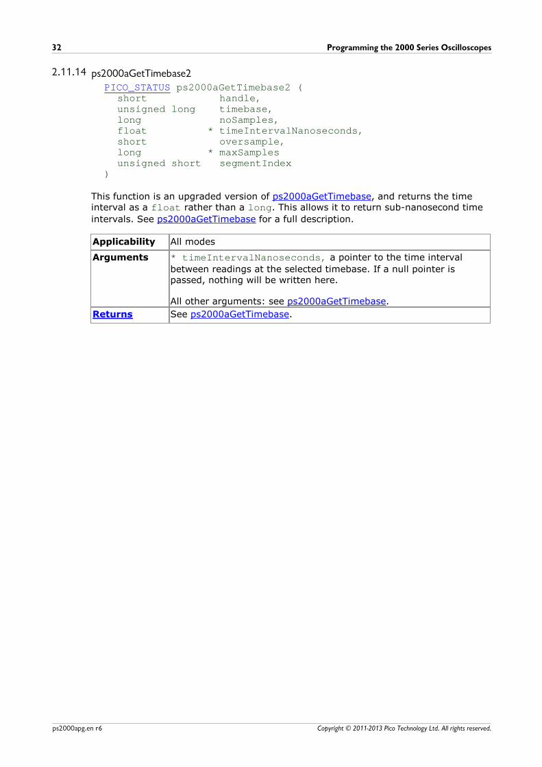
2.11.14 ps2000aGetTimebase2PICO_STATUS ps2000aGetTimebase2 (
short handle,unsigned long timebase,long noSamples,float * timeIntervalNanoseconds,short oversample,long * maxSamplesunsigned short segmentIndex
)
This function is an upgraded version of ps2000aGetTimebase, and returns the timeinterval as a float rather than a long. This allows it to return sub-nanosecond time
intervals. See ps2000aGetTimebase for a full description.
Applicability All modes
Arguments * timeIntervalNanoseconds, a pointer to the time interval
between readings at the selected timebase. If a null pointer ispassed, nothing will be written here.
All other arguments: see ps2000aGetTimebase.
Returns See ps2000aGetTimebase.
PicoScope 2000 Series (A API) Programmer's Guide 33
Copyright © 2011-2013 Pico Technology Ltd. All rights reserved. ps2000apg.en r6
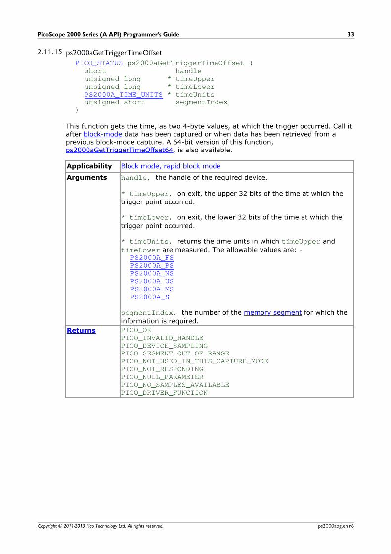
2.11.15 ps2000aGetTriggerTimeOffsetPICO_STATUS ps2000aGetTriggerTimeOffset (
short handleunsigned long * timeUpperunsigned long * timeLowerPS2000A_TIME_UNITS * timeUnitsunsigned short segmentIndex
)
This function gets the time, as two 4-byte values, at which the trigger occurred. Call itafter block-mode data has been captured or when data has been retrieved from aprevious block-mode capture. A 64-bit version of this function, ps2000aGetTriggerTimeOffset64, is also available.
Applicability Block mode, rapid block mode
Arguments handle, the handle of the required device.
* timeUpper, on exit, the upper 32 bits of the time at which the
trigger point occurred.
* timeLower, on exit, the lower 32 bits of the time at which the
trigger point occurred.
* timeUnits, returns the time units in which timeUpper and
timeLower are measured. The allowable values are: -PS2000A_FSPS2000A_PSPS2000A_NSPS2000A_USPS2000A_MSPS2000A_S
segmentIndex, the number of the memory segment for which the
information is required.
Returns PICO_OKPICO_INVALID_HANDLEPICO_DEVICE_SAMPLINGPICO_SEGMENT_OUT_OF_RANGEPICO_NOT_USED_IN_THIS_CAPTURE_MODEPICO_NOT_RESPONDINGPICO_NULL_PARAMETERPICO_NO_SAMPLES_AVAILABLEPICO_DRIVER_FUNCTION
Programming the 2000 Series Oscilloscopes34
Copyright © 2011-2013 Pico Technology Ltd. All rights reserved.ps2000apg.en r6
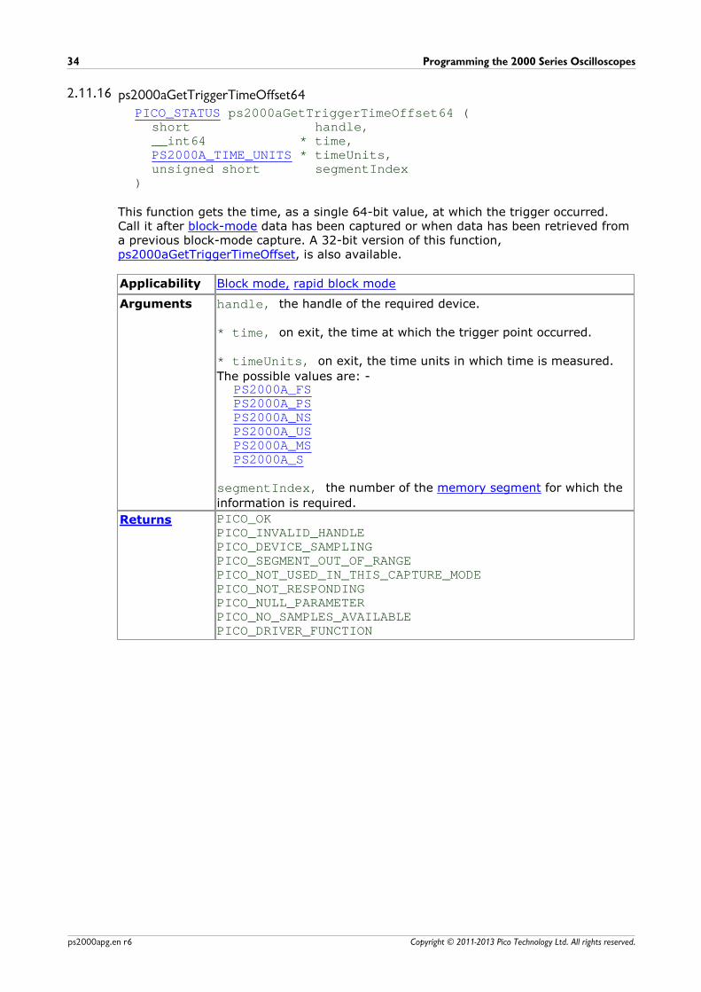
2.11.16 ps2000aGetTriggerTimeOffset64PICO_STATUS ps2000aGetTriggerTimeOffset64 (
short handle,__int64 * time,PS2000A_TIME_UNITS * timeUnits,unsigned short segmentIndex
)
This function gets the time, as a single 64-bit value, at which the trigger occurred.Call it after block-mode data has been captured or when data has been retrieved froma previous block-mode capture. A 32-bit version of this function, ps2000aGetTriggerTimeOffset, is also available.
Applicability Block mode, rapid block mode
Arguments handle, the handle of the required device.
* time, on exit, the time at which the trigger point occurred.
* timeUnits, on exit, the time units in which time is measured.
The possible values are: -PS2000A_FSPS2000A_PSPS2000A_NSPS2000A_USPS2000A_MSPS2000A_S
segmentIndex, the number of the memory segment for which the
information is required.
Returns PICO_OKPICO_INVALID_HANDLEPICO_DEVICE_SAMPLINGPICO_SEGMENT_OUT_OF_RANGEPICO_NOT_USED_IN_THIS_CAPTURE_MODEPICO_NOT_RESPONDINGPICO_NULL_PARAMETERPICO_NO_SAMPLES_AVAILABLEPICO_DRIVER_FUNCTION

PicoScope 2000 Series (A API) Programmer's Guide 35
Copyright © 2011-2013 Pico Technology Ltd. All rights reserved. ps2000apg.en r6
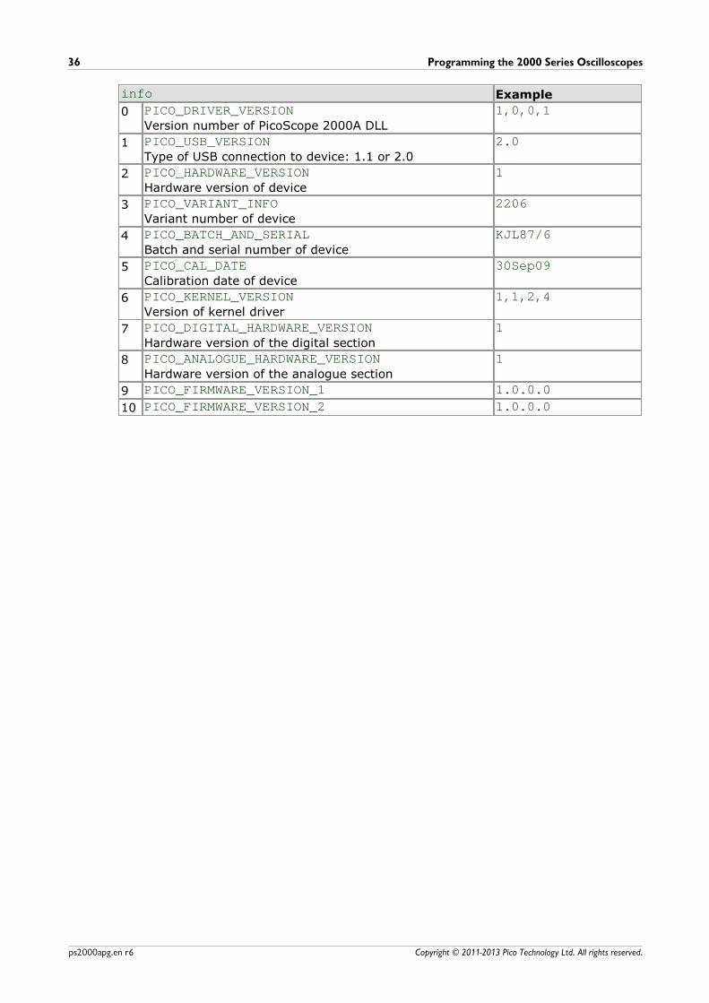
2.11.17 ps2000aGetUnitInfoPICO_STATUS ps2000aGetUnitInfo (
short handle, char * string,short stringLength,short * requiredSizePICO_INFO info
)
This function retrieves information about the specified oscilloscope. If the device failsto open, or no device is opened only the driver version is available.
Applicability All modes
Arguments handle, the handle of the device from which information is
required. If an invalid handle is passed, only the driver versions canbe read.
* string, on exit, the unit information string selected specified by
the info argument. If string is NULL, only requiredSize is
returned.
stringLength, the maximum number of chars that may be
written to string.
* requiredSize, on exit, the required length of the stringarray.
info, a number specifying what information is required. The
possible values are listed in the table below.
Returns PICO_OKPICO_INVALID_HANDLEPICO_NULL_PARAMETERPICO_INVALID_INFOPICO_INFO_UNAVAILABLEPICO_DRIVER_FUNCTION
Programming the 2000 Series Oscilloscopes36
Copyright © 2011-2013 Pico Technology Ltd. All rights reserved.ps2000apg.en r6
info Example
0 PICO_DRIVER_VERSIONVersion number of PicoScope 2000A DLL
1,0,0,1
1 PICO_USB_VERSIONType of USB connection to device: 1.1 or 2.0
2.0
2 PICO_HARDWARE_VERSIONHardware version of device
1
3 PICO_VARIANT_INFOVariant number of device
2206
4 PICO_BATCH_AND_SERIALBatch and serial number of device
KJL87/6
5 PICO_CAL_DATECalibration date of device
30Sep09
6 PICO_KERNEL_VERSIONVersion of kernel driver
1,1,2,4
7 PICO_DIGITAL_HARDWARE_VERSIONHardware version of the digital section
1
8 PICO_ANALOGUE_HARDWARE_VERSIONHardware version of the analogue section
1
9 PICO_FIRMWARE_VERSION_1 1.0.0.0
10 PICO_FIRMWARE_VERSION_2 1.0.0.0
PicoScope 2000 Series (A API) Programmer's Guide 37
Copyright © 2011-2013 Pico Technology Ltd. All rights reserved. ps2000apg.en r6
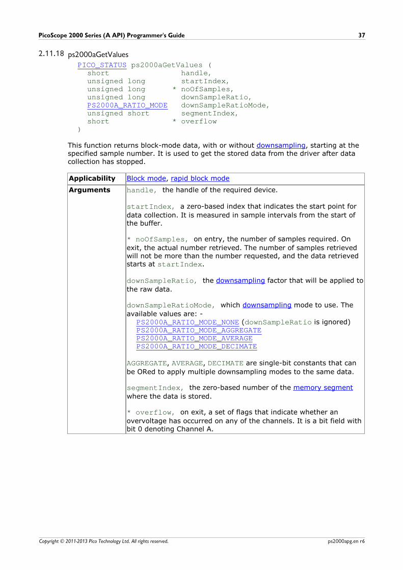
2.11.18 ps2000aGetValuesPICO_STATUS ps2000aGetValues (
short handle,unsigned long startIndex,unsigned long * noOfSamples,unsigned long downSampleRatio,PS2000A_RATIO_MODE downSampleRatioMode,unsigned short segmentIndex,short * overflow
)
This function returns block-mode data, with or without downsampling, starting at thespecified sample number. It is used to get the stored data from the driver after datacollection has stopped.
Applicability Block mode, rapid block mode
Arguments handle, the handle of the required device.
startIndex, a zero-based index that indicates the start point for
data collection. It is measured in sample intervals from the start ofthe buffer.
* noOfSamples, on entry, the number of samples required. On
exit, the actual number retrieved. The number of samples retrievedwill not be more than the number requested, and the data retrievedstarts at startIndex.
downSampleRatio, the downsampling factor that will be applied to
the raw data.
downSampleRatioMode, which downsampling mode to use. The
available values are: -PS2000A_RATIO_MODE_NONE (downSampleRatio is ignored)PS2000A_RATIO_MODE_AGGREGATEPS2000A_RATIO_MODE_AVERAGEPS2000A_RATIO_MODE_DECIMATE
AGGREGATE, AVERAGE, DECIMATE are single-bit constants that can
be ORed to apply multiple downsampling modes to the same data.
segmentIndex, the zero-based number of the memory segment
where the data is stored.
* overflow, on exit, a set of flags that indicate whether an
overvoltage has occurred on any of the channels. It is a bit field withbit 0 denoting Channel A.
Programming the 2000 Series Oscilloscopes38
Copyright © 2011-2013 Pico Technology Ltd. All rights reserved.ps2000apg.en r6
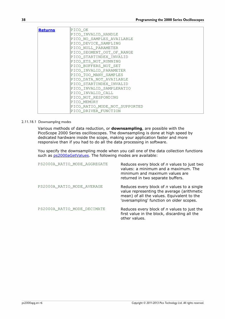
Returns PICO_OKPICO_INVALID_HANDLEPICO_NO_SAMPLES_AVAILABLEPICO_DEVICE_SAMPLINGPICO_NULL_PARAMETERPICO_SEGMENT_OUT_OF_RANGEPICO_STARTINDEX_INVALIDPICO_ETS_NOT_RUNNINGPICO_BUFFERS_NOT_SETPICO_INVALID_PARAMETERPICO_TOO_MANY_SAMPLESPICO_DATA_NOT_AVAILABLEPICO_STARTINDEX_INVALIDPICO_INVALID_SAMPLERATIOPICO_INVALID_CALLPICO_NOT_RESPONDINGPICO_MEMORYPICO_RATIO_MODE_NOT_SUPPORTEDPICO_DRIVER_FUNCTION
2.11.18.1 Downsampling modes
Various methods of data reduction, or downsampling, are possible with thePicoScope 2000 Series oscilloscopes. The downsampling is done at high speed bydedicated hardware inside the scope, making your application faster and moreresponsive than if you had to do all the data processing in software.
You specify the downsampling mode when you call one of the data collection functionssuch as ps2000aGetValues. The following modes are available:
PS2000A_RATIO_MODE_AGGREGATE Reduces every block of n values to just twovalues: a minimum and a maximum. Theminimum and maximum values arereturned in two separate buffers.
PS2000A_RATIO_MODE_AVERAGE Reduces every block of n values to a singlevalue representing the average (arithmeticmean) of all the values. Equivalent to the'oversampling' function on older scopes.
PS2000A_RATIO_MODE_DECIMATE Reduces every block of n values to just thefirst value in the block, discarding all theother values.
PicoScope 2000 Series (A API) Programmer's Guide 39
Copyright © 2011-2013 Pico Technology Ltd. All rights reserved. ps2000apg.en r6
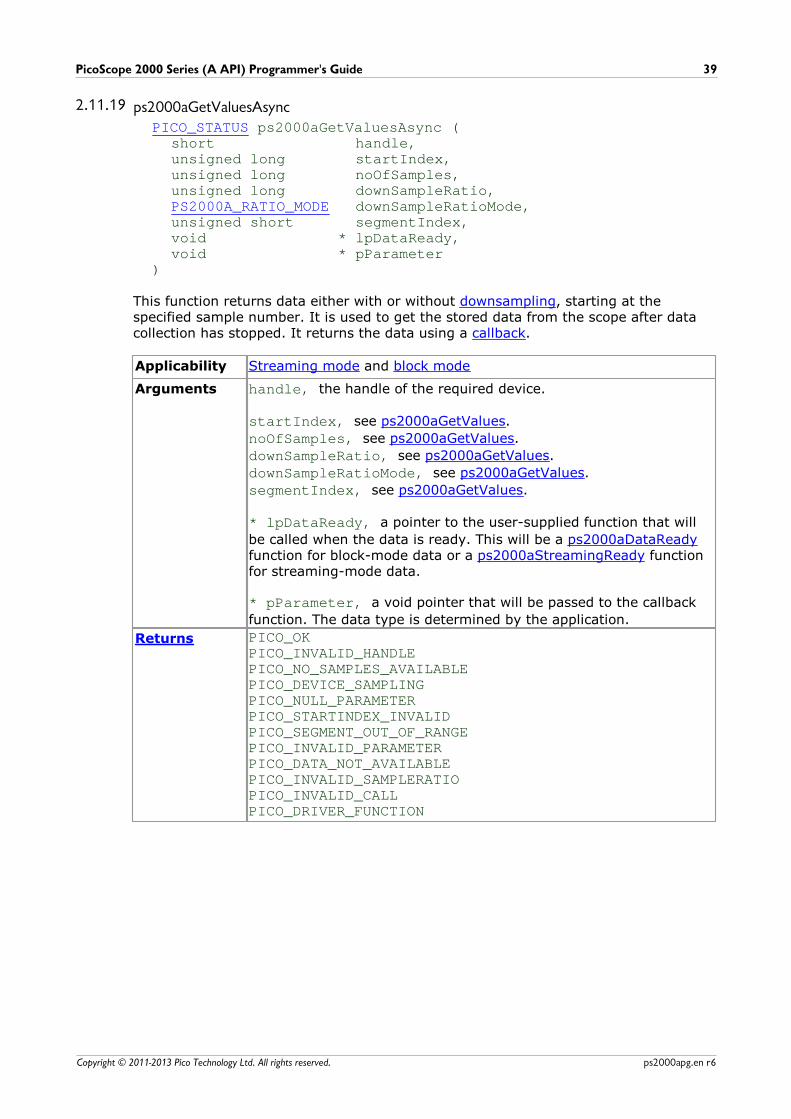
2.11.19 ps2000aGetValuesAsyncPICO_STATUS ps2000aGetValuesAsync (
short handle,unsigned long startIndex,unsigned long noOfSamples,unsigned long downSampleRatio,PS2000A_RATIO_MODE downSampleRatioMode,unsigned short segmentIndex,void * lpDataReady, void * pParameter
)
This function returns data either with or without downsampling, starting at thespecified sample number. It is used to get the stored data from the scope after datacollection has stopped. It returns the data using a callback.
Applicability Streaming mode and block mode
Arguments handle, the handle of the required device.
startIndex, see ps2000aGetValues.
noOfSamples, see ps2000aGetValues.
downSampleRatio, see ps2000aGetValues.
downSampleRatioMode, see ps2000aGetValues.
segmentIndex, see ps2000aGetValues.
* lpDataReady, a pointer to the user-supplied function that will
be called when the data is ready. This will be a ps2000aDataReadyfunction for block-mode data or a ps2000aStreamingReady functionfor streaming-mode data.
* pParameter, a void pointer that will be passed to the callback
function. The data type is determined by the application.
Returns PICO_OKPICO_INVALID_HANDLEPICO_NO_SAMPLES_AVAILABLEPICO_DEVICE_SAMPLINGPICO_NULL_PARAMETERPICO_STARTINDEX_INVALIDPICO_SEGMENT_OUT_OF_RANGEPICO_INVALID_PARAMETERPICO_DATA_NOT_AVAILABLEPICO_INVALID_SAMPLERATIOPICO_INVALID_CALLPICO_DRIVER_FUNCTION
Programming the 2000 Series Oscilloscopes40
Copyright © 2011-2013 Pico Technology Ltd. All rights reserved.ps2000apg.en r6
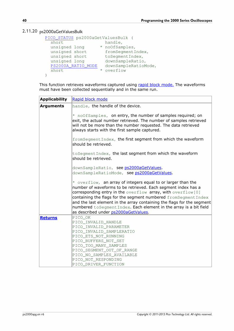
2.11.20 ps2000aGetValuesBulkPICO_STATUS ps2000aGetValuesBulk (
short handle,unsigned long * noOfSamples,unsigned short fromSegmentIndex,unsigned short toSegmentIndex,unsigned long downSampleRatio,PS2000A_RATIO_MODE downSampleRatioMode,short * overflow
)
This function retrieves waveforms captured using rapid block mode. The waveformsmust have been collected sequentially and in the same run.
Applicability Rapid block mode
Arguments handle, the handle of the device.
* noOfSamples, on entry, the number of samples required; on
exit, the actual number retrieved. The number of samples retrievedwill not be more than the number requested. The data retrievedalways starts with the first sample captured.
fromSegmentIndex, the first segment from which the waveform
should be retrieved.
toSegmentIndex, the last segment from which the waveform
should be retrieved.
downSampleRatio, see ps2000aGetValues.
downSampleRatioMode, see ps2000aGetValues.
* overflow, an array of integers equal to or larger than the
number of waveforms to be retrieved. Each segment index has acorresponding entry in the overflow array, with overflow[0]containing the flags for the segment numbered fromSegmentIndexand the last element in the array containing the flags for the segmentnumbered toSegmentIndex. Each element in the array is a bit field
as described under ps2000aGetValues.
Returns PICO_OKPICO_INVALID_HANDLEPICO_INVALID_PARAMETERPICO_INVALID_SAMPLERATIOPICO_ETS_NOT_RUNNINGPICO_BUFFERS_NOT_SETPICO_TOO_MANY_SAMPLESPICO_SEGMENT_OUT_OF_RANGEPICO_NO_SAMPLES_AVAILABLEPICO_NOT_RESPONDINGPICO_DRIVER_FUNCTION
PicoScope 2000 Series (A API) Programmer's Guide 41
Copyright © 2011-2013 Pico Technology Ltd. All rights reserved. ps2000apg.en r6
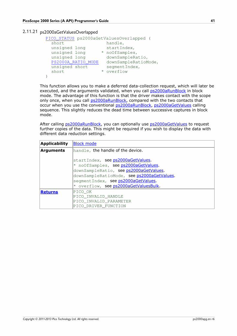
2.11.21 ps2000aGetValuesOverlappedPICO_STATUS ps2000aGetValuesOverlapped (
short handle,unsigned long startIndex,unsigned long * noOfSamples,unsigned long downSampleRatio,PS2000A_RATIO_MODE downSampleRatioMode,unsigned short segmentIndex,short * overflow
)
This function allows you to make a deferred data-collection request, which will later beexecuted, and the arguments validated, when you call ps2000aRunBlock in blockmode. The advantage of this function is that the driver makes contact with the scopeonly once, when you call ps2000aRunBlock, compared with the two contacts thatoccur when you use the conventional ps2000aRunBlock, ps2000aGetValues callingsequence. This slightly reduces the dead time between successive captures in blockmode.
After calling ps2000aRunBlock, you can optionally use ps2000aGetValues to requestfurther copies of the data. This might be required if you wish to display the data withdifferent data reduction settings.
Applicability Block mode
Arguments handle, the handle of the device.
startIndex, see ps2000aGetValues.
* noOfSamples, see ps2000aGetValues.
downSampleRatio, see ps2000aGetValues.
downSampleRatioMode, see ps2000aGetValues.
segmentIndex, see ps2000aGetValues.
* overflow, see ps2000aGetValuesBulk.
Returns PICO_OKPICO_INVALID_HANDLEPICO_INVALID_PARAMETERPICO_DRIVER_FUNCTION
Programming the 2000 Series Oscilloscopes42
Copyright © 2011-2013 Pico Technology Ltd. All rights reserved.ps2000apg.en r6
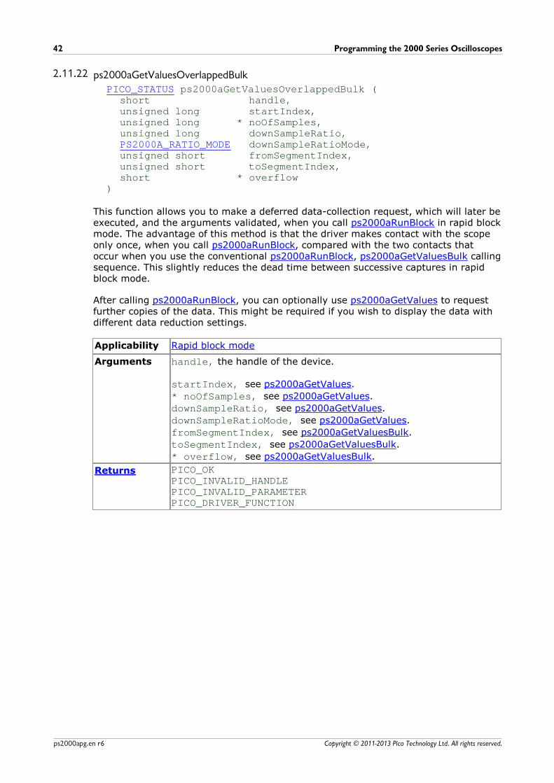
2.11.22 ps2000aGetValuesOverlappedBulkPICO_STATUS ps2000aGetValuesOverlappedBulk (
short handle,unsigned long startIndex,unsigned long * noOfSamples,unsigned long downSampleRatio,PS2000A_RATIO_MODE downSampleRatioMode,unsigned short fromSegmentIndex,unsigned short toSegmentIndex,short * overflow
)
This function allows you to make a deferred data-collection request, which will later beexecuted, and the arguments validated, when you call ps2000aRunBlock in rapid blockmode. The advantage of this method is that the driver makes contact with the scopeonly once, when you call ps2000aRunBlock, compared with the two contacts thatoccur when you use the conventional ps2000aRunBlock, ps2000aGetValuesBulk callingsequence. This slightly reduces the dead time between successive captures in rapidblock mode.
After calling ps2000aRunBlock, you can optionally use ps2000aGetValues to requestfurther copies of the data. This might be required if you wish to display the data withdifferent data reduction settings.
Applicability Rapid block mode
Arguments handle, the handle of the device.
startIndex, see ps2000aGetValues.
* noOfSamples, see ps2000aGetValues.
downSampleRatio, see ps2000aGetValues.
downSampleRatioMode, see ps2000aGetValues.
fromSegmentIndex, see ps2000aGetValuesBulk.
toSegmentIndex, see ps2000aGetValuesBulk.
* overflow, see ps2000aGetValuesBulk.
Returns PICO_OKPICO_INVALID_HANDLEPICO_INVALID_PARAMETERPICO_DRIVER_FUNCTION
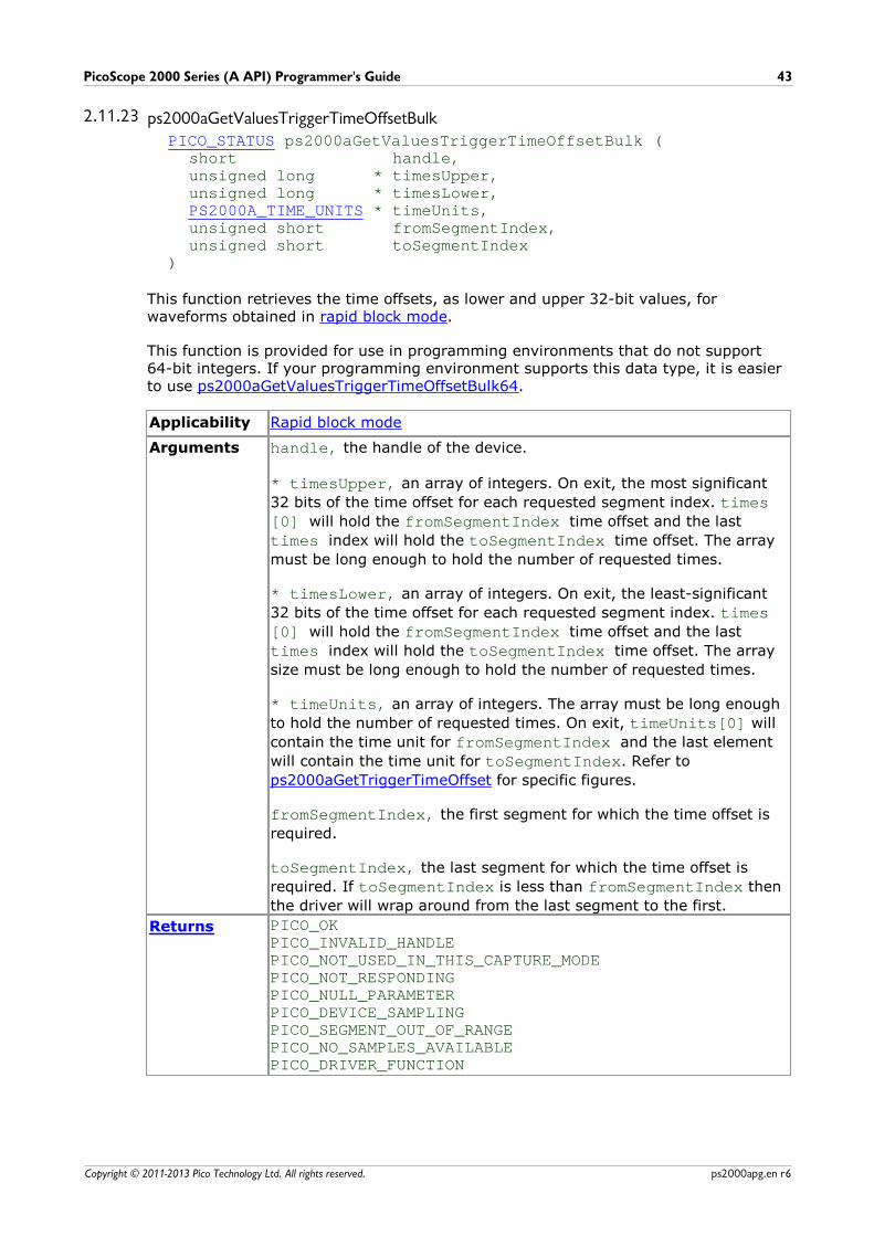
PicoScope 2000 Series (A API) Programmer's Guide 43
Copyright © 2011-2013 Pico Technology Ltd. All rights reserved. ps2000apg.en r6
2.11.23 ps2000aGetValuesTriggerTimeOffsetBulkPICO_STATUS ps2000aGetValuesTriggerTimeOffsetBulk (
short handle,unsigned long * timesUpper,unsigned long * timesLower,PS2000A_TIME_UNITS * timeUnits,unsigned short fromSegmentIndex,unsigned short toSegmentIndex
)
This function retrieves the time offsets, as lower and upper 32-bit values, forwaveforms obtained in rapid block mode.
This function is provided for use in programming environments that do not support64-bit integers. If your programming environment supports this data type, it is easierto use ps2000aGetValuesTriggerTimeOffsetBulk64.
Applicability Rapid block mode
Arguments handle, the handle of the device.
* timesUpper, an array of integers. On exit, the most significant
32 bits of the time offset for each requested segment index. times[0] will hold the fromSegmentIndex time offset and the last
times index will hold the toSegmentIndex time offset. The array
must be long enough to hold the number of requested times.
* timesLower, an array of integers. On exit, the least-significant
32 bits of the time offset for each requested segment index. times[0] will hold the fromSegmentIndex time offset and the last
times index will hold the toSegmentIndex time offset. The array
size must be long enough to hold the number of requested times.
* timeUnits, an array of integers. The array must be long enough
to hold the number of requested times. On exit, timeUnits[0] will
contain the time unit for fromSegmentIndex and the last element
will contain the time unit for toSegmentIndex. Refer to
ps2000aGetTriggerTimeOffset for specific figures.
fromSegmentIndex, the first segment for which the time offset is
required.
toSegmentIndex, the last segment for which the time offset is
required. If toSegmentIndex is less than fromSegmentIndex then
the driver will wrap around from the last segment to the first.
Returns PICO_OKPICO_INVALID_HANDLEPICO_NOT_USED_IN_THIS_CAPTURE_MODEPICO_NOT_RESPONDINGPICO_NULL_PARAMETERPICO_DEVICE_SAMPLINGPICO_SEGMENT_OUT_OF_RANGEPICO_NO_SAMPLES_AVAILABLEPICO_DRIVER_FUNCTION
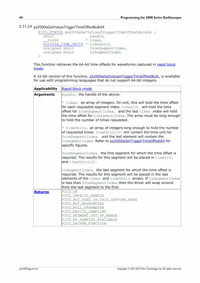
Programming the 2000 Series Oscilloscopes44
Copyright © 2011-2013 Pico Technology Ltd. All rights reserved.ps2000apg.en r6
2.11.24 ps2000aGetValuesTriggerTimeOffsetBulk64PICO_STATUS ps2000aGetValuesTriggerTimeOffsetBulk64 (
short handle,__int64 * times,PS2000A_TIME_UNITS * timeUnits,unsigned short fromSegmentIndex,unsigned short toSegmentIndex
)
This function retrieves the 64-bit time offsets for waveforms captured in rapid blockmode.
A 32-bit version of this function, ps2000aGetValuesTriggerTimeOffsetBulk, is availablefor use with programming languages that do not support 64-bit integers.
Applicability Rapid block mode
Arguments handle, the handle of the device.
* times, an array of integers. On exit, this will hold the time offset
for each requested segment index. times[0] will hold the time
offset for fromSegmentIndex, and the last times index will hold
the time offset for toSegmentIndex. The array must be long enough
to hold the number of times requested.
* timeUnits, an array of integers long enough to hold the number
of requested times. timeUnits[0] will contain the time unit for
fromSegmentIndex, and the last element will contain the
toSegmentIndex. Refer to ps2000aGetTriggerTimeOffset64 for
specific figures.
fromSegmentIndex, the first segment for which the time offset is
required. The results for this segment will be placed in times[0]and timeUnits[0].
toSegmentIndex, the last segment for which the time offset is
required. The results for this segment will be placed in the lastelements of the times and timeUnits arrays. If toSegmentIndexis less than fromSegmentIndex then the driver will wrap around
from the last segment to the first.
Returns PICO_OKPICO_INVALID_HANDLEPICO_NOT_USED_IN_THIS_CAPTURE_MODEPICO_NOT_RESPONDINGPICO_NULL_PARAMETERPICO_DEVICE_SAMPLINGPICO_SEGMENT_OUT_OF_RANGEPICO_NO_SAMPLES_AVAILABLEPICO_DRIVER_FUNCTION
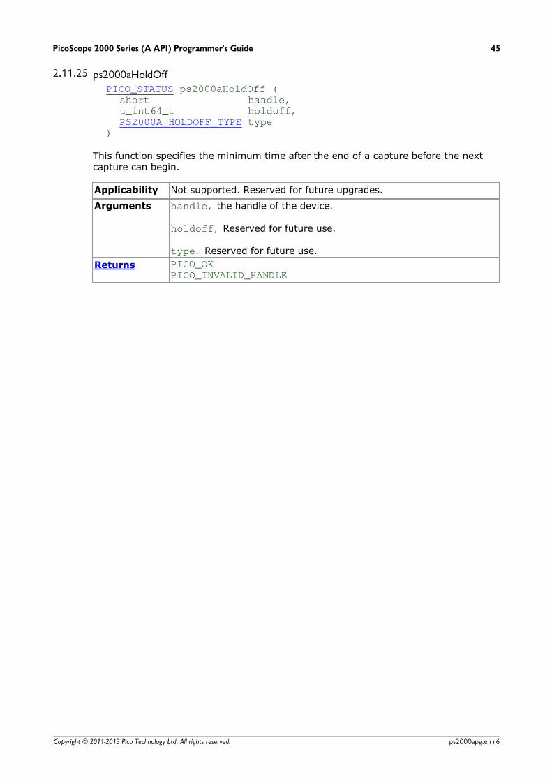
PicoScope 2000 Series (A API) Programmer's Guide 45
Copyright © 2011-2013 Pico Technology Ltd. All rights reserved. ps2000apg.en r6
2.11.25 ps2000aHoldOffPICO_STATUS ps2000aHoldOff (
short handle,u_int64_t holdoff,PS2000A_HOLDOFF_TYPE type
)
This function specifies the minimum time after the end of a capture before the nextcapture can begin.
Applicability Not supported. Reserved for future upgrades.
Arguments handle, the handle of the device.
holdoff, Reserved for future use.
type, Reserved for future use.
Returns PICO_OKPICO_INVALID_HANDLE
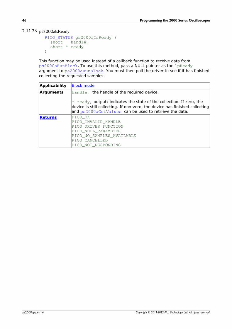
Programming the 2000 Series Oscilloscopes46
Copyright © 2011-2013 Pico Technology Ltd. All rights reserved.ps2000apg.en r6
2.11.26 ps2000aIsReadyPICO_STATUS ps2000aIsReady (
short handle, short * ready
)
This function may be used instead of a callback function to receive data from ps2000aRunBlock. To use this method, pass a NULL pointer as the lpReadyargument to ps2000aRunBlock. You must then poll the driver to see if it has finished
collecting the requested samples.
Applicability Block mode
Arguments handle, the handle of the required device.
* ready, output: indicates the state of the collection. If zero, the
device is still collecting. If non-zero, the device has finished collectingand ps2000aGetValues can be used to retrieve the data.
Returns PICO_OKPICO_INVALID_HANDLEPICO_DRIVER_FUNCTIONPICO_NULL_PARAMETERPICO_NO_SAMPLES_AVAILABLEPICO_CANCELLEDPICO_NOT_RESPONDING
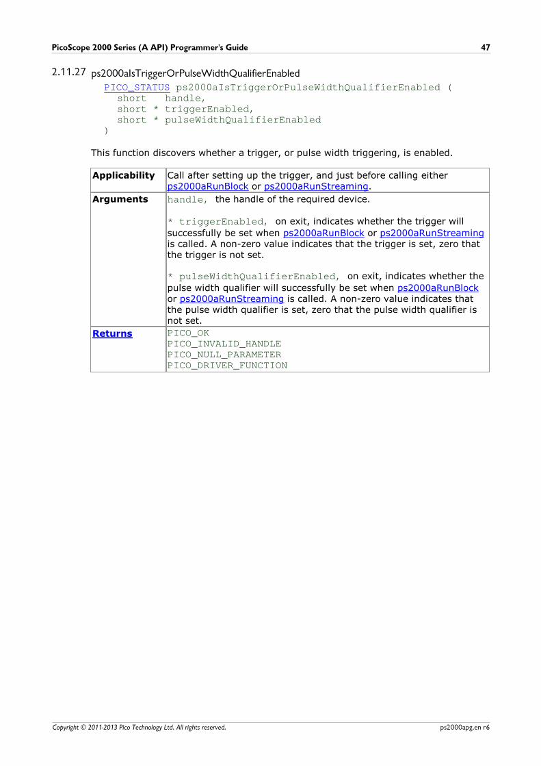
PicoScope 2000 Series (A API) Programmer's Guide 47
Copyright © 2011-2013 Pico Technology Ltd. All rights reserved. ps2000apg.en r6
2.11.27 ps2000aIsTriggerOrPulseWidthQualifierEnabledPICO_STATUS ps2000aIsTriggerOrPulseWidthQualifierEnabled (
short handle,short * triggerEnabled,short * pulseWidthQualifierEnabled
)
This function discovers whether a trigger, or pulse width triggering, is enabled.
Applicability Call after setting up the trigger, and just before calling either ps2000aRunBlock or ps2000aRunStreaming.
Arguments handle, the handle of the required device.
* triggerEnabled, on exit, indicates whether the trigger will
successfully be set when ps2000aRunBlock or ps2000aRunStreamingis called. A non-zero value indicates that the trigger is set, zero thatthe trigger is not set.
* pulseWidthQualifierEnabled, on exit, indicates whether the
pulse width qualifier will successfully be set when ps2000aRunBlockor ps2000aRunStreaming is called. A non-zero value indicates thatthe pulse width qualifier is set, zero that the pulse width qualifier isnot set.
Returns PICO_OKPICO_INVALID_HANDLEPICO_NULL_PARAMETERPICO_DRIVER_FUNCTION

Programming the 2000 Series Oscilloscopes48
Copyright © 2011-2013 Pico Technology Ltd. All rights reserved.ps2000apg.en r6
2.11.28 ps2000aMaximumValuePICO_STATUS ps2000aMaximumValue (
short handleshort * value
)
This function returns the maximum ADC count returned by calls to get values.
Applicability All modes
Arguments handle, the handle of the required device.
* value, output: the maximum ADC value.
Returns PICO_OKPICO_USER_CALLBACKPICO_INVALID_HANDLEPICO_TOO_MANY_SEGMENTSPICO_MEMORYPICO_DRIVER_FUNCTION
PicoScope 2000 Series (A API) Programmer's Guide 49
Copyright © 2011-2013 Pico Technology Ltd. All rights reserved. ps2000apg.en r6
2.11.29 ps2000aMemorySegmentsPICO_STATUS ps2000aMemorySegments (
short handleunsigned short nSegments,long * nMaxSamples
)
This function sets the number of memory segments that the scope will use.
When the scope is opened, the number of segments defaults to 1, meaning that eachcapture fills the scope's available memory. This function allows you to divide thememory into a number of segments so that the scope can store several waveformssequentially.
Applicability All modes
Arguments handle, the handle of the required device.
nSegments, the number of segments required, from 1 to 32.
* nMaxSamples, on exit, the number of samples available in each
segment. This is the total number over all channels, so if more thanone channel is in use then the number of samples available to eachchannel is nMaxSamples divided by the number of channels.
Returns PICO_OKPICO_USER_CALLBACKPICO_INVALID_HANDLEPICO_TOO_MANY_SEGMENTSPICO_MEMORYPICO_DRIVER_FUNCTION
Programming the 2000 Series Oscilloscopes50
Copyright © 2011-2013 Pico Technology Ltd. All rights reserved.ps2000apg.en r6
2.11.30 ps2000aMinimumValuePICO_STATUS ps2000aMinimumValue (
short handleshort * value
)
This function returns the minimum ADC count returned by calls to get values.
Applicability All modes
Arguments handle, the handle of the required device.
* value, output: the minimum ADC value.
Returns PICO_OKPICO_USER_CALLBACKPICO_INVALID_HANDLEPICO_TOO_MANY_SEGMENTSPICO_MEMORYPICO_DRIVER_FUNCTION
PicoScope 2000 Series (A API) Programmer's Guide 51
Copyright © 2011-2013 Pico Technology Ltd. All rights reserved. ps2000apg.en r6
2.11.31 ps2000aNoOfStreamingValuesPICO_STATUS ps2000aNoOfStreamingValues (
short handle,unsigned long * noOfValues
)
This function returns the number of samples available after data collection in streaming mode. Call it after calling ps2000aStop.
Applicability Streaming mode
Arguments handle, the handle of the required device.
* noOfValues, on exit, the number of samples.
Returns PICO_OKPICO_INVALID_HANDLEPICO_NULL_PARAMETERPICO_NO_SAMPLES_AVAILABLEPICO_NOT_USEDPICO_BUSYPICO_DRIVER_FUNCTION
Programming the 2000 Series Oscilloscopes52
Copyright © 2011-2013 Pico Technology Ltd. All rights reserved.ps2000apg.en r6
2.11.32 ps2000aOpenUnitPICO_STATUS ps2000aOpenUnit (
short * handle,char * serial
)
This function opens a PicoScope 2000 Series (A API) scope attached to the computer.The maximum number of units that can be opened depends on the operating system,the kernel driver and the computer.
Applicability All modes
Arguments * handle, on exit, the result of the attempt to open a scope: -
-1 : if the scope fails to open0 : if no scope is found> 0 : a number that uniquely identifies the scope
If a valid handle is returned, it must be used in all subsequent callsto API functions to identify this scope.
* serial, on entry, a null-terminated string containing the serial
number of the scope to be opened. If serial is NULL then the
function opens the first scope found; otherwise, it tries to open thescope that matches the string.
Returns PICO_OKPICO_OS_NOT_SUPPORTEDPICO_OPEN_OPERATION_IN_PROGRESSPICO_EEPROM_CORRUPTPICO_KERNEL_DRIVER_TOO_OLDPICO_FPGA_FAILPICO_MEMORY_CLOCK_FREQUENCYPICO_FW_FAILPICO_MAX_UNITS_OPENEDPICO_NOT_FOUND (if the specified unit was not found)PICO_NOT_RESPONDINGPICO_MEMORY_FAILPICO_ANALOG_BOARDPICO_CONFIG_FAIL_AWGPICO_INITIALISE_FPGA
PicoScope 2000 Series (A API) Programmer's Guide 53
Copyright © 2011-2013 Pico Technology Ltd. All rights reserved. ps2000apg.en r6
2.11.33 ps2000aOpenUnitAsyncPICO_STATUS ps2000aOpenUnitAsync (
short * statuschar * serial
)
This function opens a scope without blocking the calling thread. You can find out whenit has finished by periodically calling ps2000aOpenUnitProgress until that functionreturns a non-zero value.
Applicability All modes
Arguments * status, a status code: -
0 if the open operation was disallowed because another openoperation is in progress.1 if the open operation was successfully started.
* serial, see ps2000aOpenUnit.
Returns PICO_OKPICO_OPEN_OPERATION_IN_PROGRESSPICO_OPERATION_FAILED
Programming the 2000 Series Oscilloscopes54
Copyright © 2011-2013 Pico Technology Ltd. All rights reserved.ps2000apg.en r6
2.11.34 ps2000aOpenUnitProgressPICO_STATUS ps2000aOpenUnitProgress (
short * handle,short * progressPercent,short * complete
)
This function checks on the progress of a request made to ps2000aOpenUnitAsync toopen a scope.
Applicability Use after ps2000aOpenUnitAsync
Arguments * handle, see ps2000aOpenUnit. This handle is valid only if the
function returns PICO_OK.
* progressPercent, on exit, the percentage progress towards
opening the scope. 100% implies that the open operation iscomplete.
* complete, set to 1 when the open operation has finished.
Returns PICO_OKPICO_NULL_PARAMETERPICO_OPERATION_FAILED
PicoScope 2000 Series (A API) Programmer's Guide 55
Copyright © 2011-2013 Pico Technology Ltd. All rights reserved. ps2000apg.en r6
2.11.35 ps2000aPingUnitPICO_STATUS ps2000aPingUnit (
short handle)
This function can be used to check that the already opened device is still connected tothe USB port and communication is successful.
Applicability All modes
Arguments handle, the handle of the required device.
Returns PICO_OKPICO_INVALID_HANDLEPICO_DRIVER_FUNCTIONPICO_BUSYPICO_NOT_RESPONDING
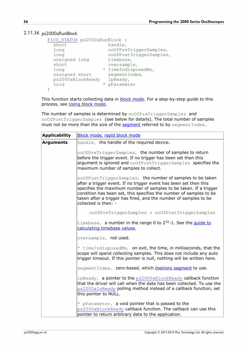
Programming the 2000 Series Oscilloscopes56
Copyright © 2011-2013 Pico Technology Ltd. All rights reserved.ps2000apg.en r6
2.11.36 ps2000aRunBlockPICO_STATUS ps2000aRunBlock (
short handle,long noOfPreTriggerSamples,long noOfPostTriggerSamples,unsigned long timebase,short oversample,long * timeIndisposedMs,unsigned short segmentIndex,ps2000aBlockReady lpReady,void * pParameter
)
This function starts collecting data in block mode. For a step-by-step guide to thisprocess, see Using block mode.
The number of samples is determined by noOfPreTriggerSamples and
noOfPostTriggerSamples (see below for details). The total number of samples
must not be more than the size of the segment referred to by segmentIndex.
Applicability Block mode, rapid block mode
Arguments handle, the handle of the required device.
noOfPreTriggerSamples, the number of samples to return
before the trigger event. If no trigger has been set then thisargument is ignored and noOfPostTriggerSamples specifies the
maximum number of samples to collect.
noOfPostTriggerSamples, the number of samples to be taken
after a trigger event. If no trigger event has been set then thisspecifies the maximum number of samples to be taken. If a triggercondition has been set, this specifies the number of samples to betaken after a trigger has fired, and the number of samples to becollected is then: -
noOfPreTriggerSamples + noOfPostTriggerSamples
timebase, a number in the range 0 to 232-1. See the guide to
calculating timebase values.
oversample, not used.
* timeIndisposedMs, on exit, the time, in milliseconds, that the
scope will spend collecting samples. This does not include any autotrigger timeout. If this pointer is null, nothing will be written here.
segmentIndex, zero-based, which memory segment to use.
lpReady, a pointer to the ps2000aBlockReady callback function
that the driver will call when the data has been collected. To use the ps2000aIsReady polling method instead of a callback function, set
this pointer to NULL.
* pParameter, a void pointer that is passed to the
ps2000aBlockReady callback function. The callback can use this
pointer to return arbitrary data to the application.
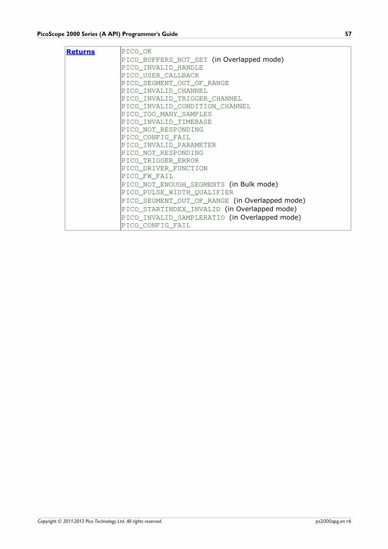
PicoScope 2000 Series (A API) Programmer's Guide 57
Copyright © 2011-2013 Pico Technology Ltd. All rights reserved. ps2000apg.en r6
Returns PICO_OKPICO_BUFFERS_NOT_SET (in Overlapped mode)PICO_INVALID_HANDLEPICO_USER_CALLBACKPICO_SEGMENT_OUT_OF_RANGEPICO_INVALID_CHANNELPICO_INVALID_TRIGGER_CHANNELPICO_INVALID_CONDITION_CHANNELPICO_TOO_MANY_SAMPLESPICO_INVALID_TIMEBASEPICO_NOT_RESPONDINGPICO_CONFIG_FAILPICO_INVALID_PARAMETERPICO_NOT_RESPONDINGPICO_TRIGGER_ERRORPICO_DRIVER_FUNCTIONPICO_FW_FAILPICO_NOT_ENOUGH_SEGMENTS (in Bulk mode)PICO_PULSE_WIDTH_QUALIFIERPICO_SEGMENT_OUT_OF_RANGE (in Overlapped mode)
PICO_STARTINDEX_INVALID (in Overlapped mode)
PICO_INVALID_SAMPLERATIO (in Overlapped mode)PICO_CONFIG_FAIL
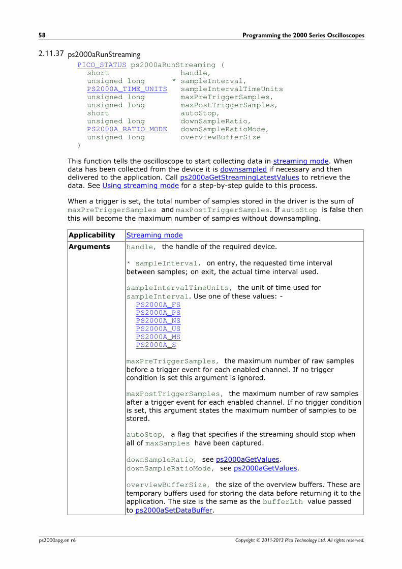
Programming the 2000 Series Oscilloscopes58
Copyright © 2011-2013 Pico Technology Ltd. All rights reserved.ps2000apg.en r6
2.11.37 ps2000aRunStreamingPICO_STATUS ps2000aRunStreaming (
short handle,unsigned long * sampleInterval,PS2000A_TIME_UNITS sampleIntervalTimeUnitsunsigned long maxPreTriggerSamples,unsigned long maxPostTriggerSamples,short autoStop,unsigned long downSampleRatio,PS2000A_RATIO_MODE downSampleRatioMode,unsigned long overviewBufferSize
)
This function tells the oscilloscope to start collecting data in streaming mode. Whendata has been collected from the device it is downsampled if necessary and thendelivered to the application. Call ps2000aGetStreamingLatestValues to retrieve thedata. See Using streaming mode for a step-by-step guide to this process.
When a trigger is set, the total number of samples stored in the driver is the sum ofmaxPreTriggerSamples and maxPostTriggerSamples. If autoStop is false then
this will become the maximum number of samples without downsampling.
Applicability Streaming mode
Arguments handle, the handle of the required device.
* sampleInterval, on entry, the requested time interval
between samples; on exit, the actual time interval used.
sampleIntervalTimeUnits, the unit of time used for
sampleInterval. Use one of these values: -PS2000A_FSPS2000A_PSPS2000A_NSPS2000A_USPS2000A_MSPS2000A_S
maxPreTriggerSamples, the maximum number of raw samples
before a trigger event for each enabled channel. If no triggercondition is set this argument is ignored.
maxPostTriggerSamples, the maximum number of raw samples
after a trigger event for each enabled channel. If no trigger conditionis set, this argument states the maximum number of samples to bestored.
autoStop, a flag that specifies if the streaming should stop when
all of maxSamples have been captured.
downSampleRatio, see ps2000aGetValues.
downSampleRatioMode, see ps2000aGetValues.
overviewBufferSize, the size of the overview buffers. These are
temporary buffers used for storing the data before returning it to theapplication. The size is the same as the bufferLth value passed
to ps2000aSetDataBuffer.
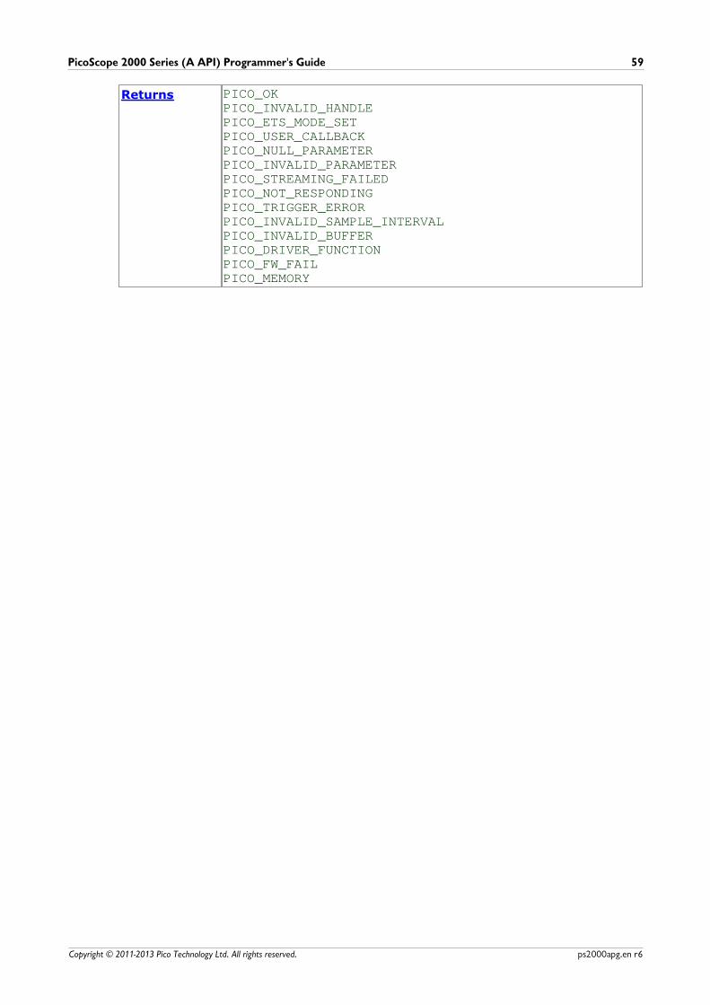
PicoScope 2000 Series (A API) Programmer's Guide 59
Copyright © 2011-2013 Pico Technology Ltd. All rights reserved. ps2000apg.en r6
Returns PICO_OKPICO_INVALID_HANDLEPICO_ETS_MODE_SETPICO_USER_CALLBACKPICO_NULL_PARAMETERPICO_INVALID_PARAMETERPICO_STREAMING_FAILEDPICO_NOT_RESPONDINGPICO_TRIGGER_ERRORPICO_INVALID_SAMPLE_INTERVALPICO_INVALID_BUFFERPICO_DRIVER_FUNCTIONPICO_FW_FAILPICO_MEMORY
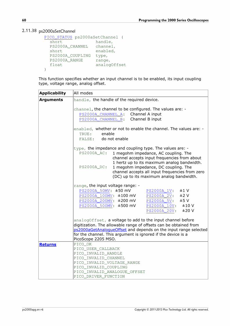
Programming the 2000 Series Oscilloscopes60
Copyright © 2011-2013 Pico Technology Ltd. All rights reserved.ps2000apg.en r6
2.11.38 ps2000aSetChannelPICO_STATUS ps2000aSetChannel (
short handle,PS2000A_CHANNEL channel,short enabled,PS2000A_COUPLING type,PS2000A_RANGE range,float analogOffset
)
This function specifies whether an input channel is to be enabled, its input couplingtype, voltage range, analog offset.
Applicability All modes
Arguments handle, the handle of the required device.
channel, the channel to be configured. The values are: -
PS2000A_CHANNEL_A: Channel A input
PS2000A_CHANNEL_B: Channel B input
enabled, whether or not to enable the channel. The values are: -
TRUE: enable
FALSE: do not enable
type, the impedance and coupling type. The values are: -PS2000A_AC: 1 megohm impedance, AC coupling. The
channel accepts input frequencies from about1 hertz up to its maximum analog bandwidth.
PS2000A_DC: 1 megohm impedance, DC coupling. Thechannel accepts all input frequencies from zero(DC) up to its maximum analog bandwidth.
range, the input voltage range: -
PS2000A_50MV: ±50 mV
PS2000A_100MV: ±100 mV
PS2000A_200MV: ±200 mV
PS2000A_500MV: ±500 mV
PS2000A_1V: ±1 V
PS2000A_2V: ±2 V
PS2000A_5V: ±5 V
PS2000A_10V: ±10 V
PS2000A_20V: ±20 V
analogOffset, a voltage to add to the input channel before
digitization. The allowable range of offsets can be obtained from ps2000aGetAnalogueOffset and depends on the input range selectedfor the channel. This argument is ignored if the device is a PicoScope 2205 MSO.
Returns PICO_OKPICO_USER_CALLBACKPICO_INVALID_HANDLEPICO_INVALID_CHANNEL PICO_INVALID_VOLTAGE_RANGEPICO_INVALID_COUPLINGPICO_INVALID_ANALOGUE_OFFSETPICO_DRIVER_FUNCTION
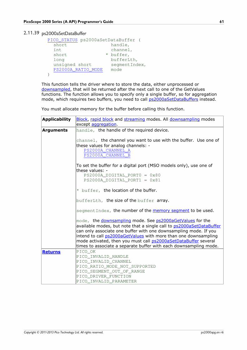
PicoScope 2000 Series (A API) Programmer's Guide 61
Copyright © 2011-2013 Pico Technology Ltd. All rights reserved. ps2000apg.en r6
2.11.39 ps2000aSetDataBufferPICO_STATUS ps2000aSetDataBuffer (
short handle,int channel,short * buffer,long bufferLth,unsigned short segmentIndex,PS2000A_RATIO_MODE mode
)
This function tells the driver where to store the data, either unprocessed or downsampled, that will be returned after the next call to one of the GetValuesfunctions. The function allows you to specify only a single buffer, so for aggregationmode, which requires two buffers, you need to call ps2000aSetDataBuffers instead.
You must allocate memory for the buffer before calling this function.
Applicability Block, rapid block and streaming modes. All downsampling modesexcept aggregation.
Arguments handle, the handle of the required device.
channel, the channel you want to use with the buffer. Use one of
these values for analog channels: -PS2000A_CHANNEL_APS2000A_CHANNEL_B
To set the buffer for a digital port (MSO models only), use one ofthese values: -
PS2000A_DIGITAL_PORT0 = 0x80PS2000A_DIGITAL_PORT1 = 0x81
* buffer, the location of the buffer.
bufferLth, the size of the buffer array.
segmentIndex, the number of the memory segment to be used.
mode, the downsampling mode. See ps2000aGetValues for the
available modes, but note that a single call to ps2000aSetDataBuffercan only associate one buffer with one downsampling mode. If youintend to call ps2000aGetValues with more than one downsamplingmode activated, then you must call ps2000aSetDataBuffer severaltimes to associate a separate buffer with each downsampling mode.
Returns PICO_OKPICO_INVALID_HANDLEPICO_INVALID_CHANNELPICO_RATIO_MODE_NOT_SUPPORTEDPICO_SEGMENT_OUT_OF_RANGEPICO_DRIVER_FUNCTIONPICO_INVALID_PARAMETER
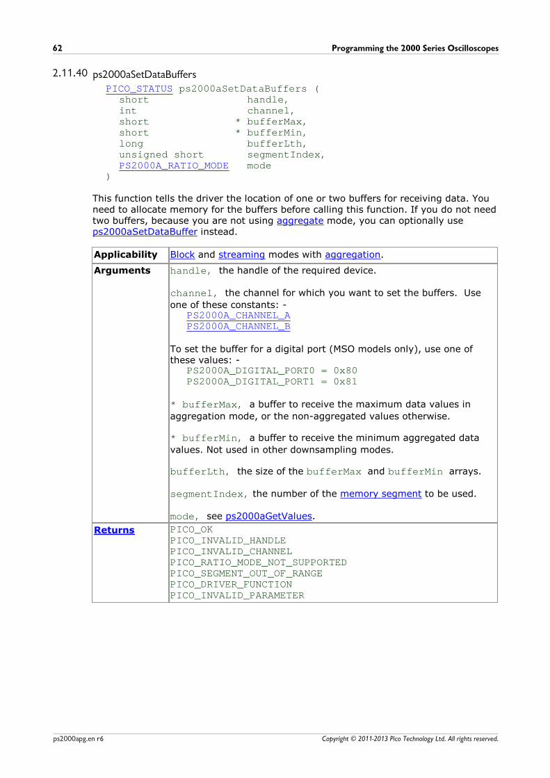
Programming the 2000 Series Oscilloscopes62
Copyright © 2011-2013 Pico Technology Ltd. All rights reserved.ps2000apg.en r6
2.11.40 ps2000aSetDataBuffersPICO_STATUS ps2000aSetDataBuffers (
short handle,int channel,short * bufferMax,short * bufferMin,long bufferLth,unsigned short segmentIndex,PS2000A_RATIO_MODE mode
)
This function tells the driver the location of one or two buffers for receiving data. Youneed to allocate memory for the buffers before calling this function. If you do not needtwo buffers, because you are not using aggregate mode, you can optionally useps2000aSetDataBuffer instead.
Applicability Block and streaming modes with aggregation.
Arguments handle, the handle of the required device.
channel, the channel for which you want to set the buffers. Use
one of these constants: -PS2000A_CHANNEL_APS2000A_CHANNEL_B
To set the buffer for a digital port (MSO models only), use one ofthese values: -
PS2000A_DIGITAL_PORT0 = 0x80PS2000A_DIGITAL_PORT1 = 0x81
* bufferMax, a buffer to receive the maximum data values in
aggregation mode, or the non-aggregated values otherwise.
* bufferMin, a buffer to receive the minimum aggregated data
values. Not used in other downsampling modes.
bufferLth, the size of the bufferMax and bufferMin arrays.
segmentIndex, the number of the memory segment to be used.
mode, see ps2000aGetValues.
Returns PICO_OKPICO_INVALID_HANDLEPICO_INVALID_CHANNELPICO_RATIO_MODE_NOT_SUPPORTEDPICO_SEGMENT_OUT_OF_RANGEPICO_DRIVER_FUNCTIONPICO_INVALID_PARAMETER
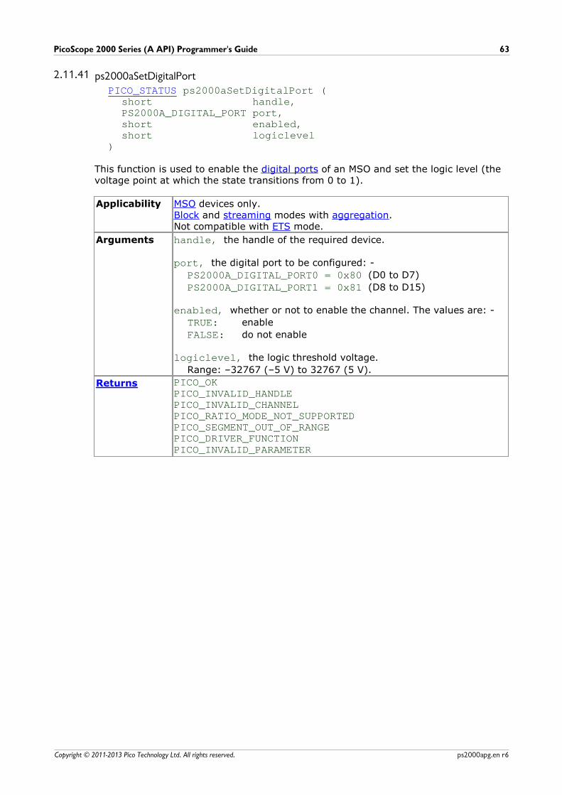
PicoScope 2000 Series (A API) Programmer's Guide 63
Copyright © 2011-2013 Pico Technology Ltd. All rights reserved. ps2000apg.en r6
2.11.41 ps2000aSetDigitalPortPICO_STATUS ps2000aSetDigitalPort (
short handle,PS2000A_DIGITAL_PORT port,short enabled,short logiclevel
)
This function is used to enable the digital ports of an MSO and set the logic level (thevoltage point at which the state transitions from 0 to 1).
Applicability MSO devices only.Block and streaming modes with aggregation.Not compatible with ETS mode.
Arguments handle, the handle of the required device.
port, the digital port to be configured: -
PS2000A_DIGITAL_PORT0 = 0x80 (D0 to D7)
PS2000A_DIGITAL_PORT1 = 0x81 (D8 to D15)
enabled, whether or not to enable the channel. The values are: -
TRUE: enable
FALSE: do not enable
logiclevel, the logic threshold voltage.
Range: –32767 (–5 V) to 32767 (5 V).
Returns PICO_OKPICO_INVALID_HANDLEPICO_INVALID_CHANNELPICO_RATIO_MODE_NOT_SUPPORTEDPICO_SEGMENT_OUT_OF_RANGEPICO_DRIVER_FUNCTIONPICO_INVALID_PARAMETER
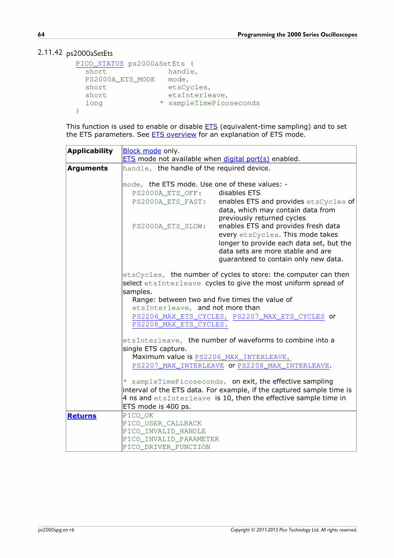
Programming the 2000 Series Oscilloscopes64
Copyright © 2011-2013 Pico Technology Ltd. All rights reserved.ps2000apg.en r6
2.11.42 ps2000aSetEtsPICO_STATUS ps2000aSetEts (
short handle,PS2000A_ETS_MODE mode,short etsCycles,short etsInterleave,long * sampleTimePicoseconds
)
This function is used to enable or disable ETS (equivalent-time sampling) and to setthe ETS parameters. See ETS overview for an explanation of ETS mode.
Applicability Block mode only.ETS mode not available when digital port(s) enabled.
Arguments handle, the handle of the required device.
mode, the ETS mode. Use one of these values: -
PS2000A_ETS_OFF: disables ETS
PS2000A_ETS_FAST: enables ETS and provides etsCycles of
data, which may contain data frompreviously returned cycles
PS2000A_ETS_SLOW: enables ETS and provides fresh data
every etsCycles. This mode takes
longer to provide each data set, but thedata sets are more stable and areguaranteed to contain only new data.
etsCycles, the number of cycles to store: the computer can then
select etsInterleave cycles to give the most uniform spread of
samples. Range: between two and five times the value of etsInterleave, and not more than
PS2206_MAX_ETS_CYCLES, PS2207_MAX_ETS_CYCLES orPS2208_MAX_ETS_CYCLES.
etsInterleave, the number of waveforms to combine into a
single ETS capture. Maximum value is PS2206_MAX_INTERLEAVE,PS2207_MAX_INTERLEAVE or PS2208_MAX_INTERLEAVE.
* sampleTimePicoseconds, on exit, the effective sampling
interval of the ETS data. For example, if the captured sample time is4 ns and etsInterleave is 10, then the effective sample time in
ETS mode is 400 ps.
Returns PICO_OKPICO_USER_CALLBACKPICO_INVALID_HANDLEPICO_INVALID_PARAMETERPICO_DRIVER_FUNCTION
PicoScope 2000 Series (A API) Programmer's Guide 65
Copyright © 2011-2013 Pico Technology Ltd. All rights reserved. ps2000apg.en r6
2.11.43 ps2000aSetEtsTimeBufferPICO_STATUS ps2000aSetEtsTimeBuffer (
short handle,__int64 * buffer,long bufferLth
)
This function tells the driver where to find your application's ETS time buffers. Thesebuffers contain the 64-bit timing information for each ETS sample after you run a block-mode ETS capture.
Applicability ETS mode only.
If your programming language does not support 64-bit data, use the32-bit version ps2000aSetEtsTimeBuffers instead.
Arguments handle, the handle of the required device.
* buffer, an array of 64-bit words, each representing the time in
picoseconds at which the sample was captured.
bufferLth, the size of the buffer array.
Returns PICO_OKPICO_INVALID_HANDLEPICO_NULL_PARAMETERPICO_DRIVER_FUNCTION
Programming the 2000 Series Oscilloscopes66
Copyright © 2011-2013 Pico Technology Ltd. All rights reserved.ps2000apg.en r6
2.11.44 ps2000aSetEtsTimeBuffersPICO_STATUS ps2000aSetEtsTimeBuffers (
short handle,unsigned long * timeUpper,unsigned long * timeLower,long bufferLth
)
This function tells the driver where to find your application's ETS time buffers. Thesebuffers contain the timing information for each ETS sample after you run a block-mode ETS capture. There are two buffers containing the upper and lower 32-bit partsof the timing information, to allow programming languages that do not support 64-bitdata to retrieve the timings.
Applicability ETS mode only.
If your programming language supports 64-bit data then you canuse ps2000aSetEtsTimeBuffer instead.
Arguments handle, the handle of the required device.
* timeUpper, an array of 32-bit words, each representing the
upper 32 bits of the time in picoseconds at which the sample wascaptured.
* timeLower, an array of 32-bit words, each representing the
lower 32 bits of the time in picoseconds at which the sample wascaptured.
bufferLth, the size of the timeUpper and timeLower arrays.
Returns PICO_OKPICO_INVALID_HANDLEPICO_NULL_PARAMETERPICO_DRIVER_FUNCTION
PicoScope 2000 Series (A API) Programmer's Guide 67
Copyright © 2011-2013 Pico Technology Ltd. All rights reserved. ps2000apg.en r6
2.11.45 ps2000aSetNoOfCapturesPICO_STATUS ps2000aSetNoOfCaptures (
short handle,unsigned short nCaptures
)
This function sets the number of captures to be collected in one run of rapid blockmode. If you do not call this function before a run, the driver will capture only onewaveform. Once a value has been set, the value remains constant unless changed.
Applicability Rapid block mode
Arguments handle, the handle of the device.
nCaptures, the number of waveforms to capture in one run.
Returns PICO_OKPICO_INVALID_HANDLEPICO_INVALID_PARAMETERPICO_DRIVER_FUNCTION
Programming the 2000 Series Oscilloscopes68
Copyright © 2011-2013 Pico Technology Ltd. All rights reserved.ps2000apg.en r6
2.11.46 ps2000aSetPulseWidthQualifierPICO_STATUS ps2000aSetPulseWidthQualifier (
short handle,PS2000A_PWQ_CONDITIONS * conditions,short nConditions,PS2000A_THRESHOLD_DIRECTION direction,unsigned long lower,unsigned long upper,PS2000A_PULSE_WIDTH_TYPE type
)
This function sets up pulse-width qualification, which can be used on its own for pulse-width triggering or combined with window triggering to produce more complextriggers. The pulse-width qualifier is set by defining one or more structures that arethen ORed together. Each structure is itself the AND of the states of one or more ofthe inputs. This AND-OR logic allows you to create any possible Boolean function ofthe scope's inputs.
Applicability All modes
Arguments handle, the handle of the required device.
* conditions, an array of PS2000A_PWQ_CONDITIONS structures
specifying the conditions that should be applied to each channel. Inthe simplest case, the array consists of a single element. When thereare several elements, the overall trigger condition is the logical OR ofall the elements. If conditions is NULL then the pulse-width
qualifier is not used.
nConditions, the number of elements in the conditions array.
If nConditions is zero then the pulse-width qualifier is not used.
Range: 0 to PS2000A_MAX_PULSE_WIDTH_QUALIFIER_COUNT.
direction, the direction of the signal required for the pulse width
trigger to fire. See PS2000A_THRESHOLD_DIRECTION constants forthe list of possible values. Each channel of the oscilloscope (exceptthe EXT input) has two thresholds for each direction—for example, PS2000A_RISING and PS2000A_RISING_LOWER—so that one can
be used for the pulse-width qualifier and the other for the leveltrigger. The driver will not let you use the same threshold for bothtriggers; so, for example, you cannot use PS2000A_RISING as the
direction argument for both ps2000aSetTriggerConditions and
ps2000aSetPulseWidthQualifier at the same time. There is no suchrestriction when using window triggers.
lower, the lower limit of the pulse-width counter with relation to
number of samples captured on the device.
upper, the upper limit of the pulse-width counter with relation to
number of samples captured on the device. This parameter is usedonly when the type is set to PS2000A_PW_TYPE_IN_RANGE or
PS2000A_PW_TYPE_OUT_OF_RANGE.
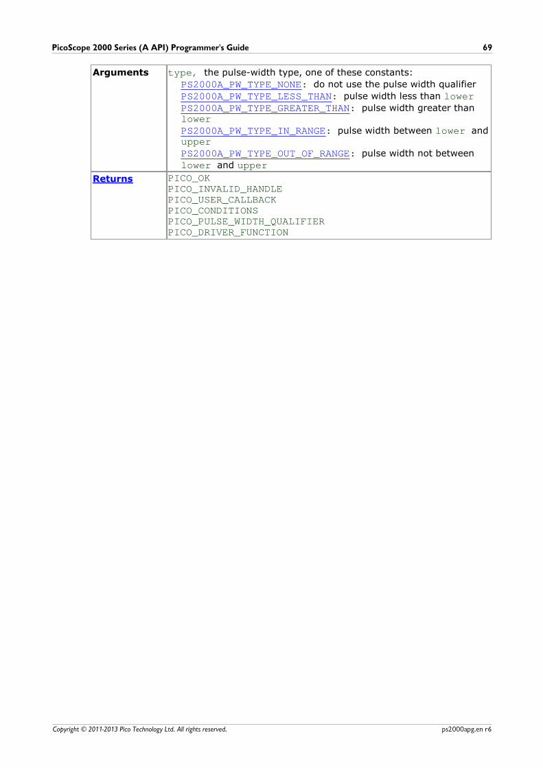
PicoScope 2000 Series (A API) Programmer's Guide 69
Copyright © 2011-2013 Pico Technology Ltd. All rights reserved. ps2000apg.en r6
Arguments type, the pulse-width type, one of these constants:
PS2000A_PW_TYPE_NONE: do not use the pulse width qualifier
PS2000A_PW_TYPE_LESS_THAN: pulse width less than lowerPS2000A_PW_TYPE_GREATER_THAN: pulse width greater thanlowerPS2000A_PW_TYPE_IN_RANGE: pulse width between lower andupperPS2000A_PW_TYPE_OUT_OF_RANGE: pulse width not between
lower and upper
Returns PICO_OKPICO_INVALID_HANDLEPICO_USER_CALLBACKPICO_CONDITIONSPICO_PULSE_WIDTH_QUALIFIERPICO_DRIVER_FUNCTION
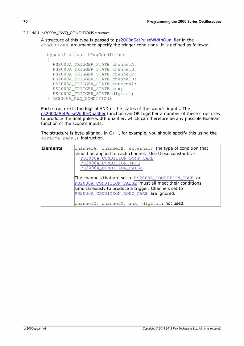
Programming the 2000 Series Oscilloscopes70
Copyright © 2011-2013 Pico Technology Ltd. All rights reserved.ps2000apg.en r6
2.11.46.1 ps2000A_PWQ_CONDITIONS structure
A structure of this type is passed to ps2000aSetPulseWidthQualifier in theconditions argument to specify the trigger conditions. It is defined as follows:
typedef struct tPwqConditions{
PS2000A_TRIGGER_STATE channelA;PS2000A_TRIGGER_STATE channelB;PS2000A_TRIGGER_STATE channelC;PS2000A_TRIGGER_STATE channelD;PS2000A_TRIGGER_STATE external;PS2000A_TRIGGER_STATE aux;PS2000A_TRIGGER_STATE digital;
} PS2000A_PWQ_CONDITIONS
Each structure is the logical AND of the states of the scope's inputs. The ps2000aSetPulseWidthQualifier function can OR together a number of these structuresto produce the final pulse width qualifier, which can therefore be any possible Booleanfunction of the scope's inputs.
The structure is byte-aligned. In C++, for example, you should specify this using the #pragma pack() instruction.
Elements channelA, channelB, external: the type of condition that
should be applied to each channel. Use these constants: -PS2000A_CONDITION_DONT_CAREPS2000A_CONDITION_TRUEPS2000A_CONDITION_FALSE
The channels that are set to PS2000A_CONDITION_TRUE or
PS2000A_CONDITION_FALSE must all meet their conditions
simultaneously to produce a trigger. Channels set to PS2000A_CONDITION_DONT_CARE are ignored.
channelC, channelD, aux, digital: not used.
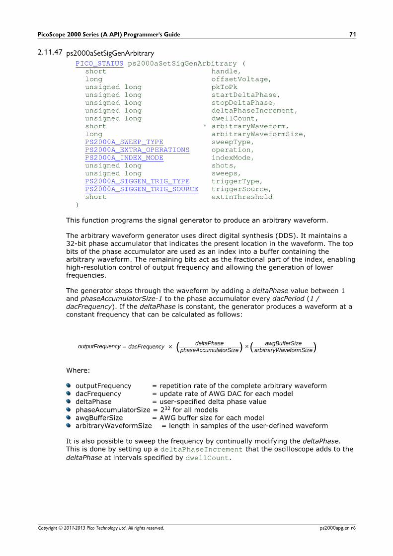
PicoScope 2000 Series (A API) Programmer's Guide 71
Copyright © 2011-2013 Pico Technology Ltd. All rights reserved. ps2000apg.en r6
2.11.47 ps2000aSetSigGenArbitraryPICO_STATUS ps2000aSetSigGenArbitrary (
short handle,long offsetVoltage,unsigned long pkToPkunsigned long startDeltaPhase,unsigned long stopDeltaPhase,unsigned long deltaPhaseIncrement, unsigned long dwellCount,short * arbitraryWaveform, long arbitraryWaveformSize,PS2000A_SWEEP_TYPE sweepType,PS2000A_EXTRA_OPERATIONS operation,PS2000A_INDEX_MODE indexMode,unsigned long shots,unsigned long sweeps,PS2000A_SIGGEN_TRIG_TYPE triggerType,PS2000A_SIGGEN_TRIG_SOURCE triggerSource,short extInThreshold
)
This function programs the signal generator to produce an arbitrary waveform.
The arbitrary waveform generator uses direct digital synthesis (DDS). It maintains a32-bit phase accumulator that indicates the present location in the waveform. The topbits of the phase accumulator are used as an index into a buffer containing thearbitrary waveform. The remaining bits act as the fractional part of the index, enablinghigh-resolution control of output frequency and allowing the generation of lowerfrequencies.
The generator steps through the waveform by adding a deltaPhase value between 1and phaseAccumulatorSize-1 to the phase accumulator every dacPeriod (1 /dacFrequency). If the deltaPhase is constant, the generator produces a waveform at aconstant frequency that can be calculated as follows:
( ) ( )outputFrequency = dacFrequency ×deltaPhase
phaseAccumulatorSize×
awgBufferSizearbitraryWaveformSize
Where:
outputFrequency = repetition rate of the complete arbitrary waveformdacFrequency = update rate of AWG DAC for each modeldeltaPhase = user-specified delta phase value
phaseAccumulatorSize = 232 for all modelsawgBufferSize = AWG buffer size for each modelarbitraryWaveformSize = length in samples of the user-defined waveform
It is also possible to sweep the frequency by continually modifying the deltaPhase.This is done by setting up a deltaPhaseIncrement that the oscilloscope adds to the
deltaPhase at intervals specified by dwellCount.
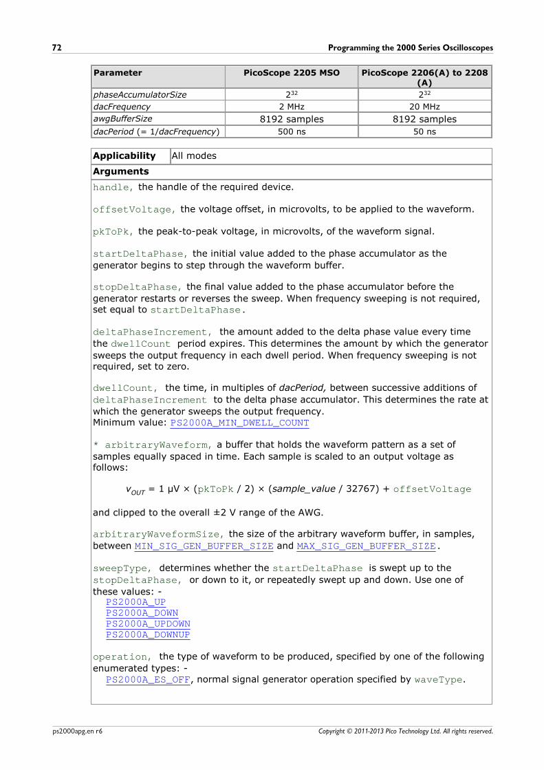
Programming the 2000 Series Oscilloscopes72
Copyright © 2011-2013 Pico Technology Ltd. All rights reserved.ps2000apg.en r6
Parameter PicoScope 2205 MSO PicoScope 2206(A) to 2208(A)
phaseAccumulatorSize 232 232
dacFrequency 2 MHz 20 MHz
awgBufferSize 8192 samples 8192 samples
dacPeriod (= 1/dacFrequency) 500 ns 50 ns
Applicability All modes
Arguments
handle, the handle of the required device.
offsetVoltage, the voltage offset, in microvolts, to be applied to the waveform.
pkToPk, the peak-to-peak voltage, in microvolts, of the waveform signal.
startDeltaPhase, the initial value added to the phase accumulator as the
generator begins to step through the waveform buffer.
stopDeltaPhase, the final value added to the phase accumulator before the
generator restarts or reverses the sweep. When frequency sweeping is not required,set equal to startDeltaPhase.
deltaPhaseIncrement, the amount added to the delta phase value every time
the dwellCount period expires. This determines the amount by which the generator
sweeps the output frequency in each dwell period. When frequency sweeping is notrequired, set to zero.
dwellCount, the time, in multiples of dacPeriod, between successive additions of
deltaPhaseIncrement to the delta phase accumulator. This determines the rate at
which the generator sweeps the output frequency. Minimum value: PS2000A_MIN_DWELL_COUNT
* arbitraryWaveform, a buffer that holds the waveform pattern as a set of
samples equally spaced in time. Each sample is scaled to an output voltage asfollows:
vOUT = 1 µV × (pkToPk / 2) × (sample_value / 32767) + offsetVoltage
and clipped to the overall ±2 V range of the AWG.
arbitraryWaveformSize, the size of the arbitrary waveform buffer, in samples,
between MIN_SIG_GEN_BUFFER_SIZE and MAX_SIG_GEN_BUFFER_SIZE.
sweepType, determines whether the startDeltaPhase is swept up to the
stopDeltaPhase, or down to it, or repeatedly swept up and down. Use one of
these values: -PS2000A_UPPS2000A_DOWNPS2000A_UPDOWNPS2000A_DOWNUP
operation, the type of waveform to be produced, specified by one of the following
enumerated types: -PS2000A_ES_OFF, normal signal generator operation specified by waveType.
PicoScope 2000 Series (A API) Programmer's Guide 73
Copyright © 2011-2013 Pico Technology Ltd. All rights reserved. ps2000apg.en r6
PS2000A_WHITENOISE, the signal generator produces white noise and ignores all
settings except offsetVoltage and pkToPk.PS2000A_PRBS, produces a random bitstream with a bit rate specified by the
phase accumulator.
indexMode, specifies how the signal will be formed from the arbitrary waveform
data. Single and dual index modes are possible. Use one of these constants: -PS2000A_SINGLEPS2000A_DUAL
shots,0: sweep the frequency as specified by sweeps1...PS2000A_MAX_SWEEPS_SHOTS: the number of cycles of the waveform to be
produced after a trigger event. sweeps must be zero.
PS2000A_SHOT_SWEEP_TRIGGER_CONTINUOUS_RUN: start and run continuously
after trigger occurs (PicoScope 2206, 2206A, 2207, 2207A, 2208 and 2208A only)
sweeps,0: produce number of cycles specified by shots1..PS2000A_MAX_SWEEPS_SHOTS: the number of times to sweep the frequency
after a trigger event, according to sweepType. shots must be zero.
PS2000A_SHOT_SWEEP_TRIGGER_CONTINUOUS_RUN: start a sweep and
continue after trigger occurs (PicoScope 2206, 2206A, 2207, 2207A, 2208 and2208A only)
triggerType, the type of trigger that will be applied to the signal generator: -PS2000A_SIGGEN_RISING trigger on rising edgePS2000A_SIGGEN_FALLING trigger on falling edgePS2000A_SIGGEN_GATE_HIGH run while trigger is highPS2000A_SIGGEN_GATE_LOW run while trigger is low
triggerSource, the source that will trigger the signal generator: -PS2000A_SIGGEN_NONE run without waiting for triggerPS2000A_SIGGEN_SCOPE_TRIG use scope triggerPS2000A_SIGGEN_EXT_IN use EXT input (if available)PS2000A_SIGGEN_SOFT_TRIG wait for software trigger provided by
ps2000aSigGenSoftwareControlPS2000A_SIGGEN_TRIGGER_RAW reserved
If a trigger source other than P2000A_SIGGEN_NONE is specified, then either
shots or sweeps, but not both, must be non-zero.
extInThreshold, trigger level, in ADC counts, for external trigger.
Returns PICO_OKPICO_AWG_NOT_SUPPORTEDPICO_BUSYPICO_INVALID_HANDLEPICO_SIG_GEN_PARAMPICO_SHOTS_SWEEPS_WARNINGPICO_NOT_RESPONDINGPICO_WARNING_EXT_THRESHOLD_CONFLICTPICO_NO_SIGNAL_GENERATOR PICO_SIGGEN_OFFSET_VOLTAGEPICO_SIGGEN_PK_TO_PKPICO_SIGGEN_OUTPUT_OVER_VOLTAGEPICO_DRIVER_FUNCTION
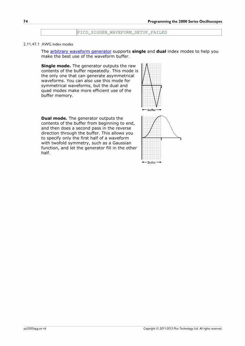
Programming the 2000 Series Oscilloscopes74
Copyright © 2011-2013 Pico Technology Ltd. All rights reserved.ps2000apg.en r6
PICO_SIGGEN_WAVEFORM_SETUP_FAILED
2.11.47.1 AWG index modes
The arbitrary waveform generator supports single and dual index modes to help youmake the best use of the waveform buffer.
Single mode. The generator outputs the rawcontents of the buffer repeatedly. This mode isthe only one that can generate asymmetricalwaveforms. You can also use this mode forsymmetrical waveforms, but the dual andquad modes make more efficient use of thebuffer memory.
Dual mode. The generator outputs thecontents of the buffer from beginning to end,and then does a second pass in the reversedirection through the buffer. This allows youto specify only the first half of a waveformwith twofold symmetry, such as a Gaussianfunction, and let the generator fill in the otherhalf.
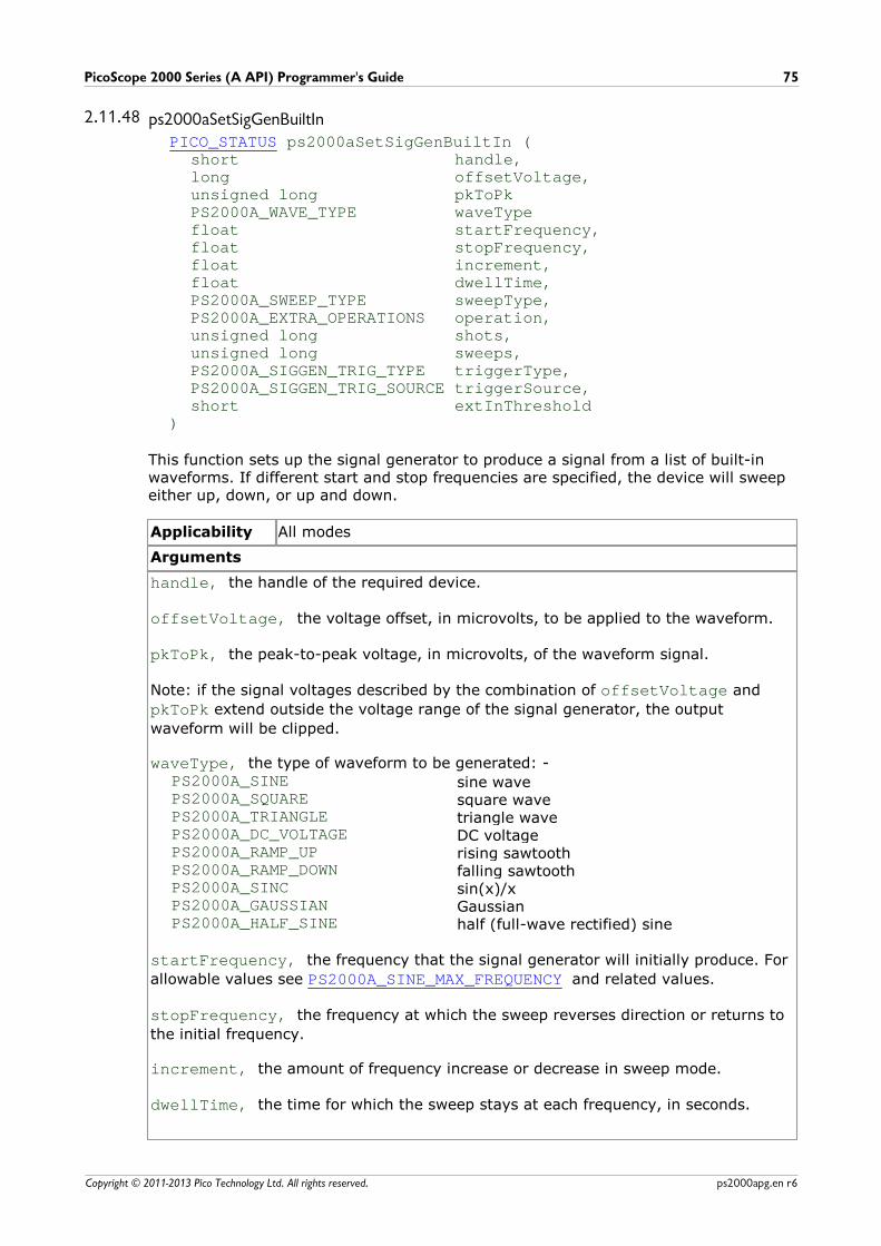
PicoScope 2000 Series (A API) Programmer's Guide 75
Copyright © 2011-2013 Pico Technology Ltd. All rights reserved. ps2000apg.en r6
2.11.48 ps2000aSetSigGenBuiltInPICO_STATUS ps2000aSetSigGenBuiltIn (
short handle,long offsetVoltage,unsigned long pkToPkPS2000A_WAVE_TYPE waveTypefloat startFrequency,float stopFrequency,float increment, float dwellTime,PS2000A_SWEEP_TYPE sweepType,PS2000A_EXTRA_OPERATIONS operation,unsigned long shots,unsigned long sweeps,PS2000A_SIGGEN_TRIG_TYPE triggerType,PS2000A_SIGGEN_TRIG_SOURCE triggerSource,short extInThreshold
)
This function sets up the signal generator to produce a signal from a list of built-inwaveforms. If different start and stop frequencies are specified, the device will sweepeither up, down, or up and down.
Applicability All modes
Arguments
handle, the handle of the required device.
offsetVoltage, the voltage offset, in microvolts, to be applied to the waveform.
pkToPk, the peak-to-peak voltage, in microvolts, of the waveform signal.
Note: if the signal voltages described by the combination of offsetVoltage and
pkToPk extend outside the voltage range of the signal generator, the output
waveform will be clipped.
waveType, the type of waveform to be generated: -PS2000A_SINE sine wavePS2000A_SQUARE square wavePS2000A_TRIANGLE triangle wavePS2000A_DC_VOLTAGE DC voltagePS2000A_RAMP_UP rising sawtoothPS2000A_RAMP_DOWN falling sawtoothPS2000A_SINC sin(x)/xPS2000A_GAUSSIAN GaussianPS2000A_HALF_SINE half (full-wave rectified) sine
startFrequency, the frequency that the signal generator will initially produce. For
allowable values see PS2000A_SINE_MAX_FREQUENCY and related values.
stopFrequency, the frequency at which the sweep reverses direction or returns to
the initial frequency.
increment, the amount of frequency increase or decrease in sweep mode.
dwellTime, the time for which the sweep stays at each frequency, in seconds.
Programming the 2000 Series Oscilloscopes76
Copyright © 2011-2013 Pico Technology Ltd. All rights reserved.ps2000apg.en r6
sweepType, whether the frequency will sweep from startFrequency to
stopFrequency, or in the opposite direction, or repeatedly reverse direction. Use
one of these constants: -PS2000A_UPPS2000A_DOWNPS2000A_UPDOWNPS2000A_DOWNUP
operation, the type of waveform to be produced, specified by one of the following
enumerated types: -PS2000A_ES_OFF, normal signal generator operation specified by waveType.
PS2000A_WHITENOISE, the signal generator produces white noise and ignores all
settings except pkToPk and offsetVoltage.PS2000A_PRBS, produces a random bitstream with a bit rate specified by the start
and stop frequency (not available on PicoScope 2205MSO).
shots, see ps2000aSigGenArbitrary.
sweeps, see ps2000aSigGenArbitrary.
triggerType, see ps2000aSigGenArbitrary.
triggerSource, see ps2000aSigGenArbitrary.
extInThreshold, see ps2000aSigGenArbitrary.
Returns PICO_OKPICO_BUSYPICO_INVALID_HANDLEPICO_SIG_GEN_PARAMPICO_SHOTS_SWEEPS_WARNINGPICO_NOT_RESPONDINGPICO_WARNING_AUX_OUTPUT_CONFLICTPICO_WARNING_EXT_THRESHOLD_CONFLICTPICO_NO_SIGNAL_GENERATORPICO_SIGGEN_OFFSET_VOLTAGEPICO_SIGGEN_PK_TO_PKPICO_SIGGEN_OUTPUT_OVER_VOLTAGEPICO_DRIVER_FUNCTIONPICO_SIGGEN_WAVEFORM_SETUP_FAILEDPICO_NOT_RESPONDING
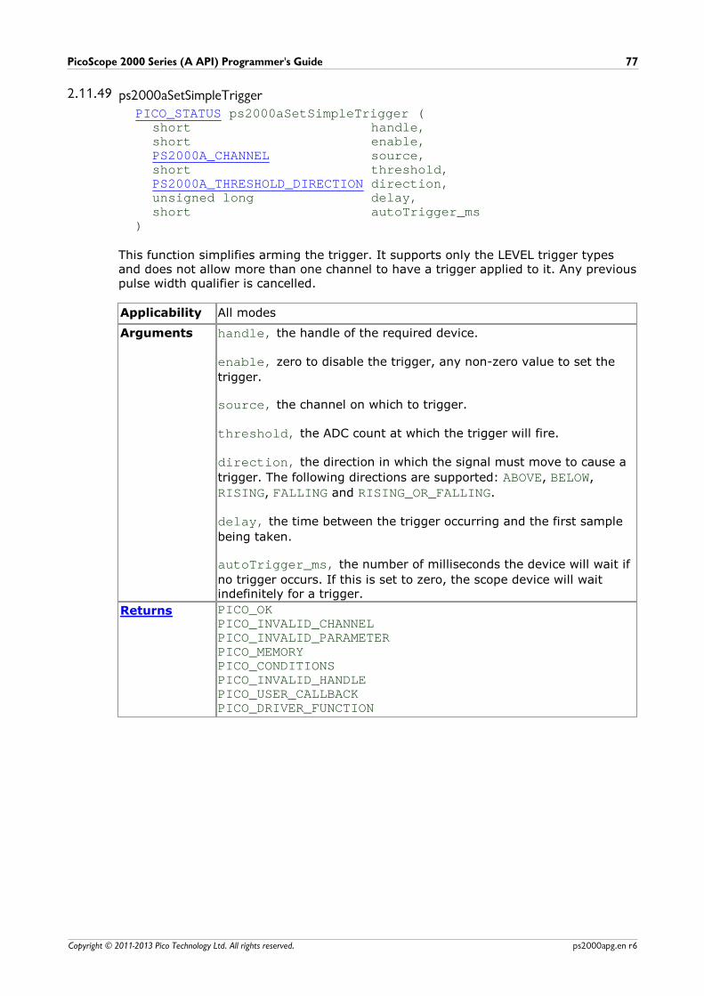
PicoScope 2000 Series (A API) Programmer's Guide 77
Copyright © 2011-2013 Pico Technology Ltd. All rights reserved. ps2000apg.en r6
2.11.49 ps2000aSetSimpleTriggerPICO_STATUS ps2000aSetSimpleTrigger (
short handle,short enable,PS2000A_CHANNEL source,short threshold,PS2000A_THRESHOLD_DIRECTION direction,unsigned long delay,short autoTrigger_ms
)
This function simplifies arming the trigger. It supports only the LEVEL trigger typesand does not allow more than one channel to have a trigger applied to it. Any previouspulse width qualifier is cancelled.
Applicability All modes
Arguments handle, the handle of the required device.
enable, zero to disable the trigger, any non-zero value to set the
trigger.
source, the channel on which to trigger.
threshold, the ADC count at which the trigger will fire.
direction, the direction in which the signal must move to cause a
trigger. The following directions are supported: ABOVE, BELOW,
RISING, FALLING and RISING_OR_FALLING.
delay, the time between the trigger occurring and the first sample
being taken.
autoTrigger_ms, the number of milliseconds the device will wait if
no trigger occurs. If this is set to zero, the scope device will waitindefinitely for a trigger.
Returns PICO_OKPICO_INVALID_CHANNELPICO_INVALID_PARAMETERPICO_MEMORYPICO_CONDITIONSPICO_INVALID_HANDLEPICO_USER_CALLBACKPICO_DRIVER_FUNCTION
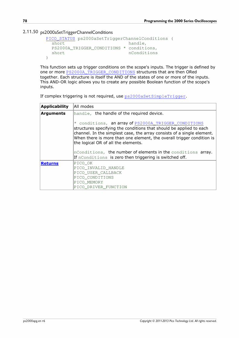
Programming the 2000 Series Oscilloscopes78
Copyright © 2011-2013 Pico Technology Ltd. All rights reserved.ps2000apg.en r6
2.11.50 ps2000aSetTriggerChannelConditionsPICO_STATUS ps2000aSetTriggerChannelConditions (
short handle,PS2000A_TRIGGER_CONDITIONS * conditions,short nConditions
)
This function sets up trigger conditions on the scope's inputs. The trigger is defined byone or more PS2000A_TRIGGER_CONDITIONS structures that are then ORed
together. Each structure is itself the AND of the states of one or more of the inputs.This AND-OR logic allows you to create any possible Boolean function of the scope'sinputs.
If complex triggering is not required, use ps2000aSetSimpleTrigger.
Applicability All modes
Arguments handle, the handle of the required device.
* conditions, an array of PS2000A_TRIGGER_CONDITIONSstructures specifying the conditions that should be applied to eachchannel. In the simplest case, the array consists of a single element.When there is more than one element, the overall trigger condition isthe logical OR of all the elements.
nConditions, the number of elements in the conditions array.
If nConditions is zero then triggering is switched off.
Returns PICO_OKPICO_INVALID_HANDLEPICO_USER_CALLBACKPICO_CONDITIONSPICO_MEMORYPICO_DRIVER_FUNCTION
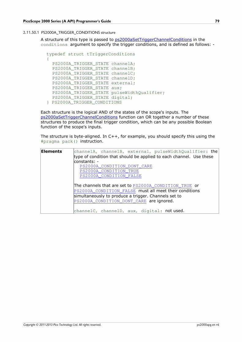
PicoScope 2000 Series (A API) Programmer's Guide 79
Copyright © 2011-2013 Pico Technology Ltd. All rights reserved. ps2000apg.en r6
2.11.50.1 PS2000A_TRIGGER_CONDITIONS structure
A structure of this type is passed to ps2000aSetTriggerChannelConditions in theconditions argument to specify the trigger conditions, and is defined as follows: -
typedef struct tTriggerConditions{
PS2000A_TRIGGER_STATE channelA;PS2000A_TRIGGER_STATE channelB;PS2000A_TRIGGER_STATE channelC;PS2000A_TRIGGER_STATE channelD;PS2000A_TRIGGER_STATE external;PS2000A_TRIGGER_STATE aux;PS2000A_TRIGGER_STATE pulseWidthQualifier;PS2000A_TRIGGER_STATE digital;
} PS2000A_TRIGGER_CONDITIONS
Each structure is the logical AND of the states of the scope's inputs. The ps2000aSetTriggerChannelConditions function can OR together a number of thesestructures to produce the final trigger condition, which can be any possible Booleanfunction of the scope's inputs.
The structure is byte-aligned. In C++, for example, you should specify this using the #pragma pack() instruction.
Elements channelA, channelB, external, pulseWidthQualifier: the
type of condition that should be applied to each channel. Use theseconstants: -
PS2000A_CONDITION_DONT_CAREPS2000A_CONDITION_TRUEPS2000A_CONDITION_FALSE
The channels that are set to PS2000A_CONDITION_TRUE or
PS2000A_CONDITION_FALSE must all meet their conditions
simultaneously to produce a trigger. Channels set to PS2000A_CONDITION_DONT_CARE are ignored.
channelC, channelD, aux, digital: not used.
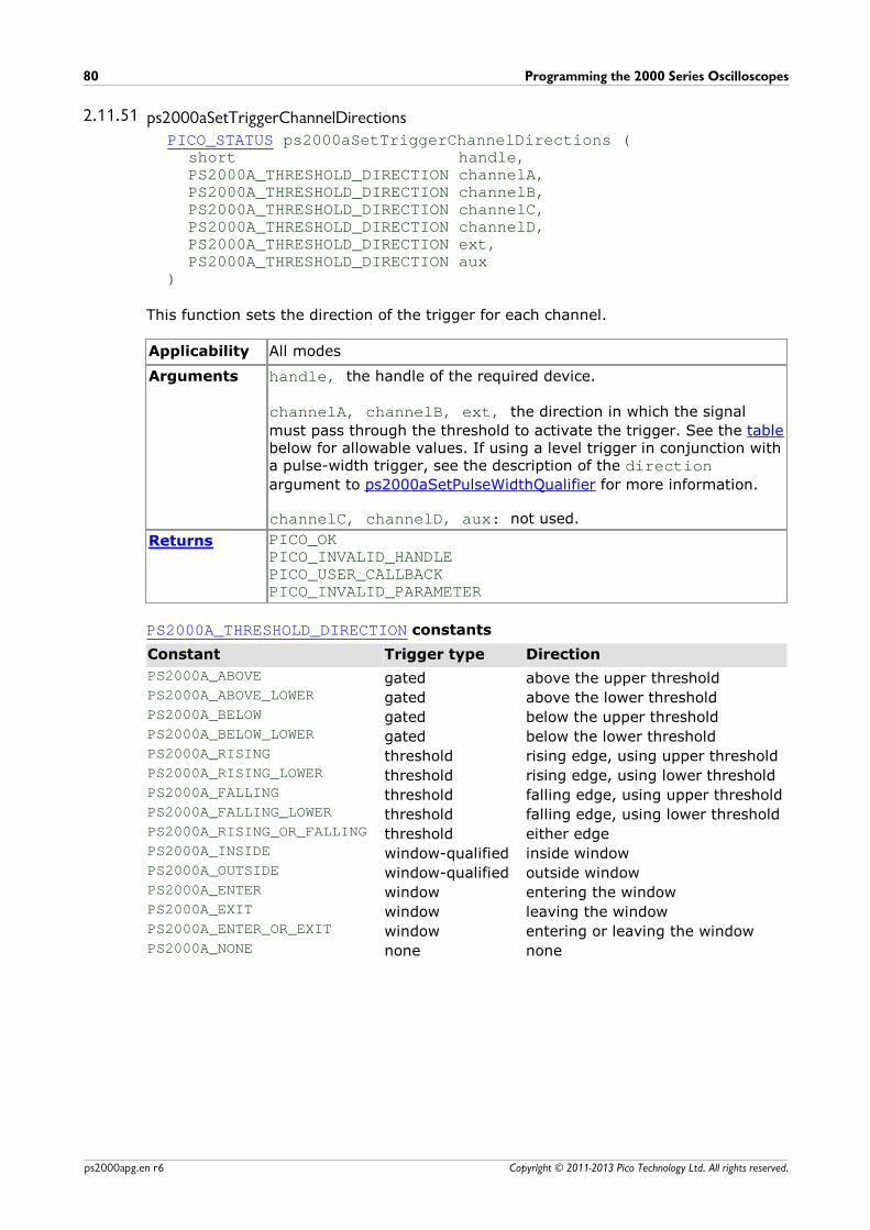
Programming the 2000 Series Oscilloscopes80
Copyright © 2011-2013 Pico Technology Ltd. All rights reserved.ps2000apg.en r6
2.11.51 ps2000aSetTriggerChannelDirectionsPICO_STATUS ps2000aSetTriggerChannelDirections (
short handle,PS2000A_THRESHOLD_DIRECTION channelA,PS2000A_THRESHOLD_DIRECTION channelB,PS2000A_THRESHOLD_DIRECTION channelC,PS2000A_THRESHOLD_DIRECTION channelD,PS2000A_THRESHOLD_DIRECTION ext,PS2000A_THRESHOLD_DIRECTION aux
)
This function sets the direction of the trigger for each channel.
Applicability All modes
Arguments handle, the handle of the required device.
channelA, channelB, ext, the direction in which the signal
must pass through the threshold to activate the trigger. See the tablebelow for allowable values. If using a level trigger in conjunction witha pulse-width trigger, see the description of the directionargument to ps2000aSetPulseWidthQualifier for more information.
channelC, channelD, aux: not used.
Returns PICO_OKPICO_INVALID_HANDLEPICO_USER_CALLBACKPICO_INVALID_PARAMETER
PS2000A_THRESHOLD_DIRECTION constants
Constant Trigger type Direction
PS2000A_ABOVE gated above the upper thresholdPS2000A_ABOVE_LOWER gated above the lower thresholdPS2000A_BELOW gated below the upper thresholdPS2000A_BELOW_LOWER gated below the lower thresholdPS2000A_RISING threshold rising edge, using upper thresholdPS2000A_RISING_LOWER threshold rising edge, using lower thresholdPS2000A_FALLING threshold falling edge, using upper thresholdPS2000A_FALLING_LOWER threshold falling edge, using lower thresholdPS2000A_RISING_OR_FALLING threshold either edgePS2000A_INSIDE window-qualified inside windowPS2000A_OUTSIDE window-qualified outside windowPS2000A_ENTER window entering the windowPS2000A_EXIT window leaving the windowPS2000A_ENTER_OR_EXIT window entering or leaving the windowPS2000A_NONE none none
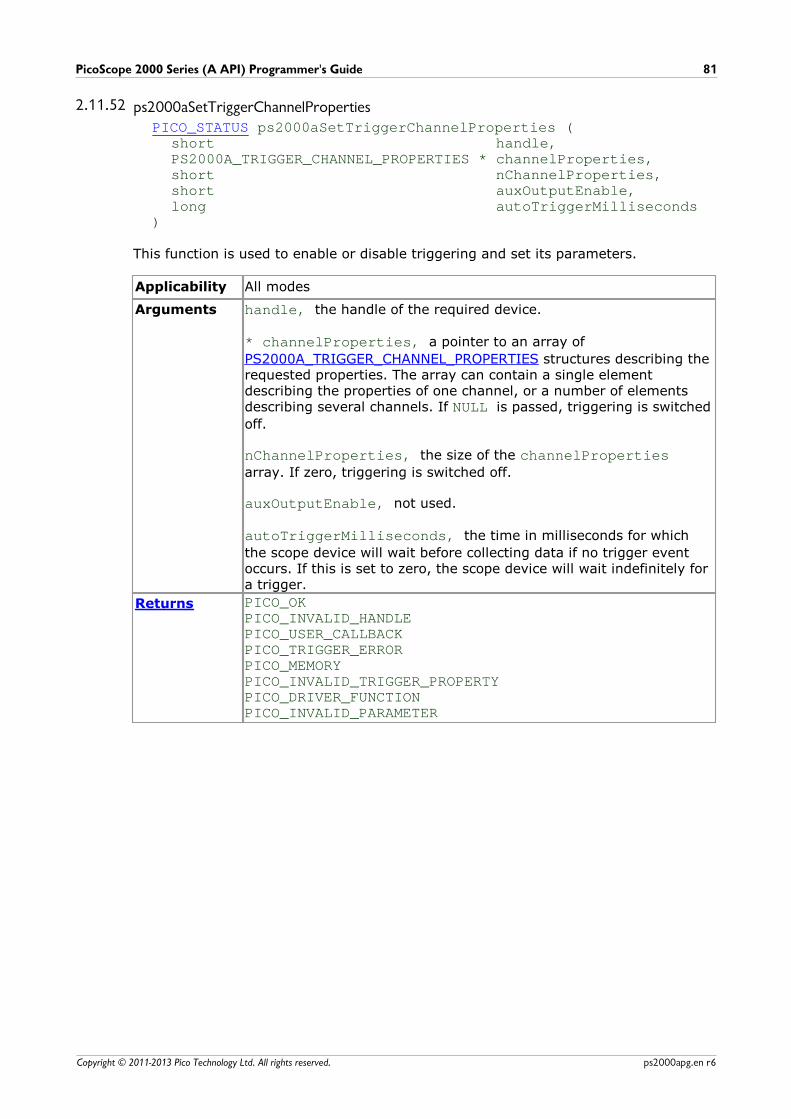
PicoScope 2000 Series (A API) Programmer's Guide 81
Copyright © 2011-2013 Pico Technology Ltd. All rights reserved. ps2000apg.en r6
2.11.52 ps2000aSetTriggerChannelPropertiesPICO_STATUS ps2000aSetTriggerChannelProperties (
short handle,PS2000A_TRIGGER_CHANNEL_PROPERTIES * channelProperties,short nChannelProperties,short auxOutputEnable,long autoTriggerMilliseconds
)
This function is used to enable or disable triggering and set its parameters.
Applicability All modes
Arguments handle, the handle of the required device.
* channelProperties, a pointer to an array of
PS2000A_TRIGGER_CHANNEL_PROPERTIES structures describing therequested properties. The array can contain a single elementdescribing the properties of one channel, or a number of elementsdescribing several channels. If NULL is passed, triggering is switched
off.
nChannelProperties, the size of the channelPropertiesarray. If zero, triggering is switched off.
auxOutputEnable, not used.
autoTriggerMilliseconds, the time in milliseconds for which
the scope device will wait before collecting data if no trigger eventoccurs. If this is set to zero, the scope device will wait indefinitely fora trigger.
Returns PICO_OKPICO_INVALID_HANDLEPICO_USER_CALLBACKPICO_TRIGGER_ERRORPICO_MEMORYPICO_INVALID_TRIGGER_PROPERTYPICO_DRIVER_FUNCTIONPICO_INVALID_PARAMETER
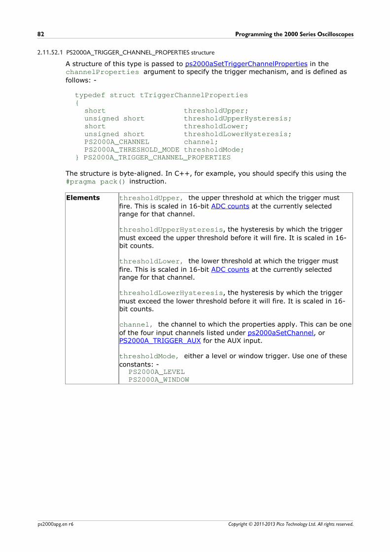
Programming the 2000 Series Oscilloscopes82
Copyright © 2011-2013 Pico Technology Ltd. All rights reserved.ps2000apg.en r6
2.11.52.1 PS2000A_TRIGGER_CHANNEL_PROPERTIES structure
A structure of this type is passed to ps2000aSetTriggerChannelProperties in thechannelProperties argument to specify the trigger mechanism, and is defined as
follows: -
typedef struct tTriggerChannelProperties{
short thresholdUpper;unsigned short thresholdUpperHysteresis;short thresholdLower;unsigned short thresholdLowerHysteresis;PS2000A_CHANNEL channel;PS2000A_THRESHOLD_MODE thresholdMode;
} PS2000A_TRIGGER_CHANNEL_PROPERTIES
The structure is byte-aligned. In C++, for example, you should specify this using the #pragma pack() instruction.
Elements thresholdUpper, the upper threshold at which the trigger must
fire. This is scaled in 16-bit ADC counts at the currently selectedrange for that channel.
thresholdUpperHysteresis, the hysteresis by which the trigger
must exceed the upper threshold before it will fire. It is scaled in 16-bit counts.
thresholdLower, the lower threshold at which the trigger must
fire. This is scaled in 16-bit ADC counts at the currently selectedrange for that channel.
thresholdLowerHysteresis, the hysteresis by which the trigger
must exceed the lower threshold before it will fire. It is scaled in 16-bit counts.
channel, the channel to which the properties apply. This can be one
of the four input channels listed under ps2000aSetChannel, orPS2000A_TRIGGER_AUX for the AUX input.
thresholdMode, either a level or window trigger. Use one of these
constants: -PS2000A_LEVELPS2000A_WINDOW
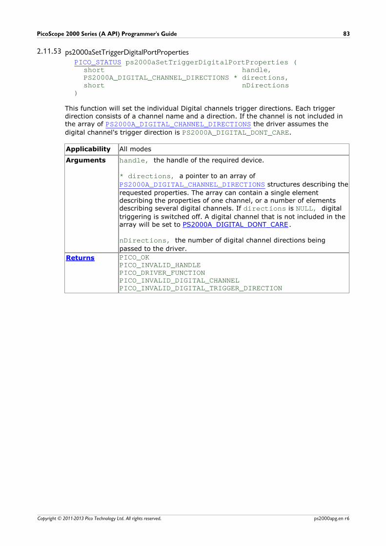
PicoScope 2000 Series (A API) Programmer's Guide 83
Copyright © 2011-2013 Pico Technology Ltd. All rights reserved. ps2000apg.en r6
2.11.53 ps2000aSetTriggerDigitalPortPropertiesPICO_STATUS ps2000aSetTriggerDigitalPortProperties (
short handle,PS2000A_DIGITAL_CHANNEL_DIRECTIONS * directions,short nDirections
)
This function will set the individual Digital channels trigger directions. Each triggerdirection consists of a channel name and a direction. If the channel is not included inthe array of PS2000A_DIGITAL_CHANNEL_DIRECTIONS the driver assumes the
digital channel's trigger direction is PS2000A_DIGITAL_DONT_CARE.
Applicability All modes
Arguments handle, the handle of the required device.
* directions, a pointer to an array of
PS2000A_DIGITAL_CHANNEL_DIRECTIONS structures describing the
requested properties. The array can contain a single elementdescribing the properties of one channel, or a number of elementsdescribing several digital channels. If directions is NULL, digital
triggering is switched off. A digital channel that is not included in thearray will be set to PS2000A_DIGITAL_DONT_CARE.
nDirections, the number of digital channel directions being
passed to the driver.
Returns PICO_OKPICO_INVALID_HANDLEPICO_DRIVER_FUNCTIONPICO_INVALID_DIGITAL_CHANNELPICO_INVALID_DIGITAL_TRIGGER_DIRECTION
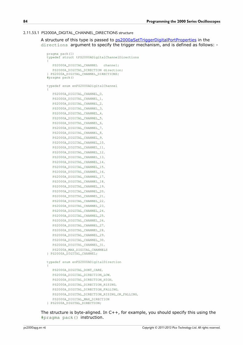
Programming the 2000 Series Oscilloscopes84
Copyright © 2011-2013 Pico Technology Ltd. All rights reserved.ps2000apg.en r6
2.11.53.1 PS2000A_DIGITAL_CHANNEL_DIRECTIONS structure
A structure of this type is passed to ps2000aSetTriggerDigitalPortProperties in thedirections argument to specify the trigger mechanism, and is defined as follows: -
pragma pack(1)typedef struct tPS2000ADigitalChannelDirections{
PS2000A_DIGITAL_CHANNEL channel;
PS2000A_DIGITAL_DIRECTION direction;} PS2000A_DIGITAL_CHANNEL_DIRECTIONS;#pragma pack()
typedef enum enPS2000ADigitalChannel{
PS2000A_DIGITAL_CHANNEL_0,
PS2000A_DIGITAL_CHANNEL_1,
PS2000A_DIGITAL_CHANNEL_2,
PS2000A_DIGITAL_CHANNEL_3,
PS2000A_DIGITAL_CHANNEL_4,
PS2000A_DIGITAL_CHANNEL_5,
PS2000A_DIGITAL_CHANNEL_6,
PS2000A_DIGITAL_CHANNEL_7,
PS2000A_DIGITAL_CHANNEL_8,
PS2000A_DIGITAL_CHANNEL_9,
PS2000A_DIGITAL_CHANNEL_10,
PS2000A_DIGITAL_CHANNEL_11,
PS2000A_DIGITAL_CHANNEL_12,
PS2000A_DIGITAL_CHANNEL_13,
PS2000A_DIGITAL_CHANNEL_14,
PS2000A_DIGITAL_CHANNEL_15,
PS2000A_DIGITAL_CHANNEL_16,
PS2000A_DIGITAL_CHANNEL_17,
PS2000A_DIGITAL_CHANNEL_18,
PS2000A_DIGITAL_CHANNEL_19,
PS2000A_DIGITAL_CHANNEL_20,
PS2000A_DIGITAL_CHANNEL_21,
PS2000A_DIGITAL_CHANNEL_22,
PS2000A_DIGITAL_CHANNEL_23,
PS2000A_DIGITAL_CHANNEL_24,
PS2000A_DIGITAL_CHANNEL_25,
PS2000A_DIGITAL_CHANNEL_26,
PS2000A_DIGITAL_CHANNEL_27,
PS2000A_DIGITAL_CHANNEL_28,
PS2000A_DIGITAL_CHANNEL_29,
PS2000A_DIGITAL_CHANNEL_30,
PS2000A_DIGITAL_CHANNEL_31,
PS2000A_MAX_DIGITAL_CHANNELS} PS2000A_DIGITAL_CHANNEL;
typedef enum enPS2000ADigitalDirection{
PS2000A_DIGITAL_DONT_CARE,
PS2000A_DIGITAL_DIRECTION_LOW,
PS2000A_DIGITAL_DIRECTION_HIGH,
PS2000A_DIGITAL_DIRECTION_RISING,
PS2000A_DIGITAL_DIRECTION_FALLING,
PS2000A_DIGITAL_DIRECTION_RISING_OR_FALLING,
PS2000A_DIGITAL_MAX_DIRECTION} PS2000A_DIGITAL_DIRECTION;
The structure is byte-aligned. In C++, for example, you should specify this using the #pragma pack() instruction.
PicoScope 2000 Series (A API) Programmer's Guide 85
Copyright © 2011-2013 Pico Technology Ltd. All rights reserved. ps2000apg.en r6
2.11.54 ps2000aSetTriggerDelayPICO_STATUS ps2000aSetTriggerDelay (
short handle,unsigned long delay
)
This function sets the post-trigger delay, which causes capture to start a defined timeafter the trigger event.
Applicability All modes
Arguments handle, the handle of the required device.
delay, the time between the trigger occurring and the first sample.
For example, if delay=100 then the scope would wait 100 sample
periods before sampling. At a timebase of 1 GS/s, or 1 ns per sample,the total delay would then be 100 x 1 ns = 100 ns.
Range: 0 to MAX_DELAY_COUNT
Returns PICO_OKPICO_INVALID_HANDLEPICO_USER_CALLBACKPICO_DRIVER_FUNCTION
Programming the 2000 Series Oscilloscopes86
Copyright © 2011-2013 Pico Technology Ltd. All rights reserved.ps2000apg.en r6
2.11.55 ps2000aSigGenSoftwareControlPICO_STATUS ps2000aSigGenSoftwareControl (
short handle,short state
)
This function causes a trigger event, or starts and stops gating. Use it as follows:
1. Call ps2000aSetSigGenBuiltIn or ps2000aSetSigGenArbitrary to set up the signalgenerator, setting the triggerSource argument to SIGGEN_SOFT_TRIG.
2. (a) If you set the signal generator triggerType to edge triggering
(PS2000A_SIGGEN_RISING or PS2000A_SIGGEN_FALLING), call
ps2000aSigGenSoftwareControl once to trigger a capture.(b) If you set the signal generator triggerType to gated triggering
(PS2000A_SIGGEN_GATE_HIGH or PS2000A_SIGGEN_GATE_LOW), call
ps2000aSigGenSoftwareControl with state set to 0 to start capture, and then
again with state set to 1 to stop capture.
Applicability Use with ps2000aSetSigGenBuiltIn or ps2000aSetSigGenArbitrary.
Arguments handle, the handle of the required device.
state, sets the trigger gate high or low when the signal generator
triggerType is set to either SIGGEN_GATE_HIGH or
SIGGEN_GATE_LOW. Ignored for other trigger types.
0 switch the trigger gate off
1 switch the trigger gate on
Returns PICO_OKPICO_INVALID_HANDLEPICO_NO_SIGNAL_GENERATORPICO_SIGGEN_TRIGGER_SOURCEPICO_DRIVER_FUNCTIONPICO_NOT_RESPONDING
PicoScope 2000 Series (A API) Programmer's Guide 87
Copyright © 2011-2013 Pico Technology Ltd. All rights reserved. ps2000apg.en r6
2.11.56 ps2000aStopPICO_STATUS ps2000aStop (
short handle)
This function stops the scope device from sampling data. If this function is calledbefore a trigger event occurs, the oscilloscope may not contain valid data.
Always call this function after the end of a capture to ensure that the scope is readyfor the next capture.
Applicability All modes
Arguments handle, the handle of the required device.
Returns PICO_OKPICO_INVALID_HANDLEPICO_USER_CALLBACKPICO_DRIVER_FUNCTION
Programming the 2000 Series Oscilloscopes88
Copyright © 2011-2013 Pico Technology Ltd. All rights reserved.ps2000apg.en r6
2.11.57 ps2000aStreamingReadytypedef void (CALLBACK *ps2000aStreamingReady) (
short handle,long noOfSamples,unsigned long startIndex,short overflow,unsigned long triggerAt,short triggered,short autoStop,void * pParameter
)
This callback function is part of your application. You register it with the driver usingps2000aGetStreamingLatestValues, and the driver calls it back when streaming-modedata is ready. You can then download the data using the ps2000aGetValuesAsyncfunction.
Applicability Streaming mode only
Arguments handle, the handle of the device returning the samples.
noOfSamples, the number of samples to collect.
startIndex, an index to the first valid sample in the buffer. This is
the buffer that was previously passed to ps2000aSetDataBuffer.
overflow, returns a set of flags that indicate whether an
overvoltage has occurred on any of the channels. It is a bit patternwith bit 0 denoting Channel A.
triggerAt, an index to the buffer indicating the location of the
trigger point. This parameter is valid only when triggered is non-
zero.
triggered, a flag indicating whether a trigger occurred. If non-
zero, a trigger occurred at the location indicated by triggerAt.
autoStop, the flag that was set in the call to
ps2000aRunStreaming.
* pParameter, a void pointer passed from
ps2000aGetStreamingLatestValues. The callback function can writeto this location to send any data, such as a status flag, back to theapplication.
Returns nothing
PicoScope 2000 Series (A API) Programmer's Guide 89
Copyright © 2011-2013 Pico Technology Ltd. All rights reserved. ps2000apg.en r6
2.12 Programming examplesYour PicoScope installation includes programming examples in the following languagesand development environments:
C Excel LabVIEW
2.12.1 C
The C example program is a comprehensive console mode program that demonstratesall of the facilities of the driver.
To compile the program, create a new project for an Application containing thefollowing files: -
ps2000acon.c
and:
ps2000a.lib (Microsoft Visual C 32-bit applications)
The following files must be in the compilation directory:
ps2000aApi.h picoStatus.h
and the following file must be in the same directory as the executable:
ps2000a.dll
2.12.2 Excel
1. Load the spreadsheet ps2000a.xls2. Select Tools | Macro3. Select GetData4. Select Run
Note: The Excel macro language is similar to Visual Basic. The functions which returna TRUE/FALSE value, return 0 for FALSE and 1 for TRUE, whereas Visual Basic
expects 65 535 for TRUE. Check for >0 rather than =TRUE.
2.12.3 LabVIEW
The SDK contains a library of VIs that can be used to control the PicoScope 2000Series scopes and some simple examples of using these VIs in streaming mode, blockmode and rapid block mode.
The LabVIEW library (PicoScope2000A.llb) can be placed in the user.lib sub-
directory to make the VIs available on the ‘User Libraries’ palette. You must also copy ps2000a.dll and ps2000awrap.dll to the folder containing your LabView project.
The library contains the following VIs:
PicoErrorHandler.vi - takes an error cluster and, if an error has occurred,
displays a message box indicating the source of the error and the status codereturned by the driver.
Programming the 2000 Series Oscilloscopes90
Copyright © 2011-2013 Pico Technology Ltd. All rights reserved.ps2000apg.en r6
PicoScope2000AAdvancedTriggerSettings.vi - an interface for the
advanced trigger features of the oscilloscope.
This VI is not required for setting up simple triggers, which are configured using PicoScope2000ASettings.vi.
For further information on these trigger settings, see descriptions of the triggerfunctions:
ps2000aSetTriggerChannelConditionsps2000aSetTriggerChannelDirectionsps2000aSetTriggerChannelPropertiesps2000aSetPulseWidthQualifierps2000aSetTriggerDelay
PicoScope2000AAWG.vi - controls the arbitrary waveform generator.
Standard waveforms or an arbitrary waveform can be selected under ‘Wave Type’.There are three settings clusters: general settings that apply to both arbitrary andstandard waveforms, settings that apply only to standard waveforms and settings thatapply only to arbitrary waveforms. It is not necessary to connect all of these clusters ifonly using arbitrary waveforms or only using standard waveforms.
When selecting an arbitrary waveform, it is necessary to specify a text file containingthe waveform. This text file should have a single value on each line in the range -1 to1. For further information on the settings, see descriptions of ps2000aSetSigGenBuiltIn and ps2000aSetSigGenArbitrary.
PicoScope2000AClose.vi - closes the oscilloscope.
Should be called before exiting an application.
PicoScope2000AGetBlock.vi - collects a block of data from the oscilloscope.
This can be called in a loop in order to continually collect blocks of data. Theoscilloscope should first be set up by using PicoScope2000ASettings.vi. The VI
outputs data arrays in two clusters (max and min). If not using aggregation, ‘MinBuffers’ is not used.
PicoScope2000AGetRapidBlock.vi - collects a set of data blocks or captures
from the oscilloscope in rapid block mode.
This VI is similar to PicoScope2000AGetBlock.vi. It outputs two-dimensional
arrays for each channel that contain data from all the requested number of captures.
PicoScope2000AGetStreamingValues.vi - used in streaming mode to get the
latest values from the driver.
This VI should be called in a loop after the oscilloscope has been set up using PicoScope2000ASettings.vi and streaming has been started by calling
PicoScope2000AStartStreaming.vi. The VI outputs the number of samples
available and the start index of these samples in the array output by PicoScope2000AStartStreaming.vi.
PicoScope 2000 Series (A API) Programmer's Guide 91
Copyright © 2011-2013 Pico Technology Ltd. All rights reserved. ps2000apg.en r6
PicoScope2000AOpen.vi - opens a PicoScope 2000A and returns a handle to the
device
PicoScope2000ASettings.vi - sets up the oscilloscope.
The inputs are clusters for setting up channels and simple triggers. Advanced triggerscan be set up using PicoScope2000AAdvancedTriggerSettings.vi.
PicoScope2000AStartStreaming.vi - starts the oscilloscope streaming.
It outputs arrays that will contain samples once PicoScope2000AGetStreamingValues.vi has returned.
PicoStatus.vi - checks the status value returned by calls to the driver.
If the driver returns an error, the status member of the error cluster is set to ‘true’and the error code and source are set.
Programming the 2000 Series Oscilloscopes92
Copyright © 2011-2013 Pico Technology Ltd. All rights reserved.ps2000apg.en r6
2.13 Driver status codesEvery function in the ps2000a driver returns a driver status code from the followinglist of PICO_STATUS values. These definitions can also be found in the file
picoStatus.h, which is included in the PicoScope 2000 Series (A API) SDK.
Code(hex)
Symbol and meaning
00 PICO_OK. The oscilloscope is functioning correctly.
01 PICO_MAX_UNITS_OPENED. An attempt has been made to open more than
PS2000A_MAX_UNITS devices.
02 PICO_MEMORY_FAIL. Not enough memory could be allocated on the host
machine.03 PICO_NOT_FOUND. No PicoScope 2000 Series device could be found.
04 PICO_FW_FAIL. Unable to download firmware.
05 PICO_OPEN_OPERATION_IN_PROGRESS
06 PICO_OPERATION_FAILED
07 PICO_NOT_RESPONDING. The PicoScope is not responding to commands from
the PC.08 PICO_CONFIG_FAIL. The configuration information in the oscilloscope is
corrupt or missing.09 PICO_KERNEL_DRIVER_TOO_OLD. The picopp.sys file is too old to be used
with the device driver.0A PICO_EEPROM_CORRUPT. The EEPROM is corrupt, so the device will use a
default setting.0B PICO_OS_NOT_SUPPORTED. The operating system on the PC is not supported
by this driver.0C PICO_INVALID_HANDLE. There is no device with the specified handle.
0D PICO_INVALID_PARAMETER. A parameter is not valid.
0E PICO_INVALID_TIMEBASE. The timebase is not supported or is invalid.
0F PICO_INVALID_VOLTAGE_RANGE. The voltage range is not supported or is
invalid.10 PICO_INVALID_CHANNEL. The channel number is not valid on this device or
no channels have been set.11 PICO_INVALID_TRIGGER_CHANNEL. The channel set for a trigger is not
available on this device.12 PICO_INVALID_CONDITION_CHANNEL. The channel set for a condition is not
available on this device.14 PICO_STREAMING_FAILED. Streaming has failed to start or has stopped
without user request.15 PICO_BLOCK_MODE_FAILED. Block failed to start - a parameter may have
been set wrongly.16 PICO_NULL_PARAMETER. A parameter that was required is NULL.
18 PICO_DATA_NOT_AVAILABLE. No data is available from a run block call.
19 PICO_STRING_BUFFER_TOO_SMALL. The buffer passed for the information was
too small.1A PICO_ETS_NOT_SUPPORTED. ETS is not supported on this device.
1B PICO_AUTO_TRIGGER_TIME_TOO_SHORT. The auto trigger time is less than the
time it will take to collect the pre-trigger data.1C PICO_BUFFER_STALL. The collection of data has stalled as unread data would
be overwritten.
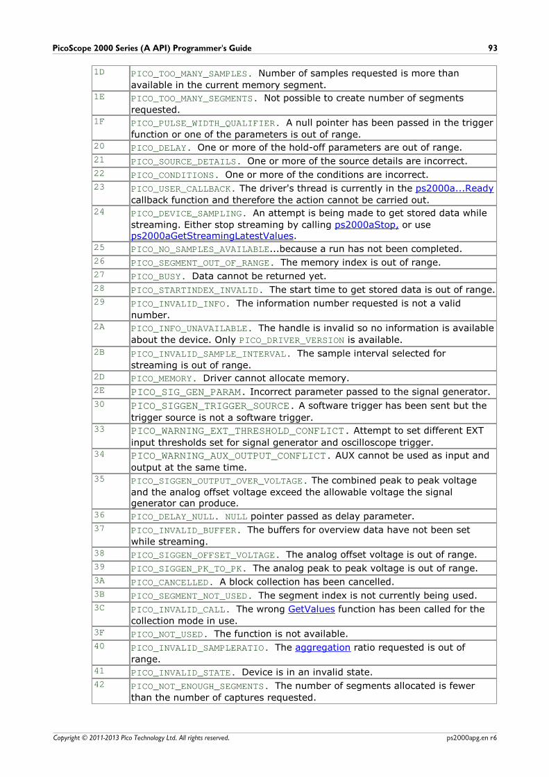
PicoScope 2000 Series (A API) Programmer's Guide 93
Copyright © 2011-2013 Pico Technology Ltd. All rights reserved. ps2000apg.en r6
1D PICO_TOO_MANY_SAMPLES. Number of samples requested is more than
available in the current memory segment.1E PICO_TOO_MANY_SEGMENTS. Not possible to create number of segments
requested.1F PICO_PULSE_WIDTH_QUALIFIER. A null pointer has been passed in the trigger
function or one of the parameters is out of range.20 PICO_DELAY. One or more of the hold-off parameters are out of range.
21 PICO_SOURCE_DETAILS. One or more of the source details are incorrect.
22 PICO_CONDITIONS. One or more of the conditions are incorrect.
23 PICO_USER_CALLBACK. The driver's thread is currently in the ps2000a...Ready
callback function and therefore the action cannot be carried out.24 PICO_DEVICE_SAMPLING. An attempt is being made to get stored data while
streaming. Either stop streaming by calling ps2000aStop, or useps2000aGetStreamingLatestValues.
25 PICO_NO_SAMPLES_AVAILABLE...because a run has not been completed.
26 PICO_SEGMENT_OUT_OF_RANGE. The memory index is out of range.
27 PICO_BUSY. Data cannot be returned yet.
28 PICO_STARTINDEX_INVALID. The start time to get stored data is out of range.
29 PICO_INVALID_INFO. The information number requested is not a valid
number.2A PICO_INFO_UNAVAILABLE. The handle is invalid so no information is available
about the device. Only PICO_DRIVER_VERSION is available.
2B PICO_INVALID_SAMPLE_INTERVAL. The sample interval selected for
streaming is out of range.2D PICO_MEMORY. Driver cannot allocate memory.
2E PICO_SIG_GEN_PARAM. Incorrect parameter passed to the signal generator.
30 PICO_SIGGEN_TRIGGER_SOURCE. A software trigger has been sent but the
trigger source is not a software trigger.33 PICO_WARNING_EXT_THRESHOLD_CONFLICT. Attempt to set different EXT
input thresholds set for signal generator and oscilloscope trigger.34 PICO_WARNING_AUX_OUTPUT_CONFLICT. AUX cannot be used as input and
output at the same time.35 PICO_SIGGEN_OUTPUT_OVER_VOLTAGE. The combined peak to peak voltage
and the analog offset voltage exceed the allowable voltage the signalgenerator can produce.
36 PICO_DELAY_NULL. NULL pointer passed as delay parameter.
37 PICO_INVALID_BUFFER. The buffers for overview data have not been set
while streaming.38 PICO_SIGGEN_OFFSET_VOLTAGE. The analog offset voltage is out of range.
39 PICO_SIGGEN_PK_TO_PK. The analog peak to peak voltage is out of range.
3A PICO_CANCELLED. A block collection has been cancelled.
3B PICO_SEGMENT_NOT_USED. The segment index is not currently being used.
3C PICO_INVALID_CALL. The wrong GetValues function has been called for the
collection mode in use.3F PICO_NOT_USED. The function is not available.
40 PICO_INVALID_SAMPLERATIO. The aggregation ratio requested is out of
range.41 PICO_INVALID_STATE. Device is in an invalid state.
42 PICO_NOT_ENOUGH_SEGMENTS. The number of segments allocated is fewer
than the number of captures requested.
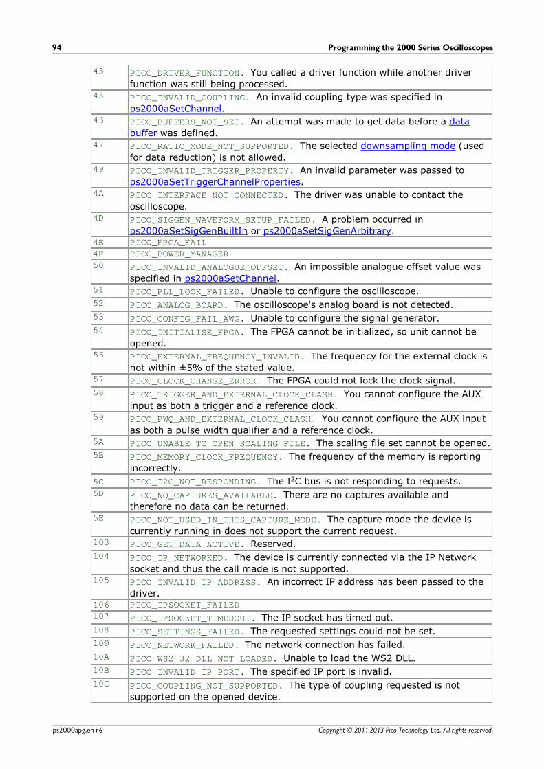
Programming the 2000 Series Oscilloscopes94
Copyright © 2011-2013 Pico Technology Ltd. All rights reserved.ps2000apg.en r6
43 PICO_DRIVER_FUNCTION. You called a driver function while another driver
function was still being processed.45 PICO_INVALID_COUPLING. An invalid coupling type was specified in
ps2000aSetChannel.46 PICO_BUFFERS_NOT_SET. An attempt was made to get data before a data
buffer was defined.47 PICO_RATIO_MODE_NOT_SUPPORTED. The selected downsampling mode (used
for data reduction) is not allowed.49 PICO_INVALID_TRIGGER_PROPERTY. An invalid parameter was passed to
ps2000aSetTriggerChannelProperties.4A PICO_INTERFACE_NOT_CONNECTED. The driver was unable to contact the
oscilloscope.4D PICO_SIGGEN_WAVEFORM_SETUP_FAILED. A problem occurred in
ps2000aSetSigGenBuiltIn or ps2000aSetSigGenArbitrary.4E PICO_FPGA_FAIL
4F PICO_POWER_MANAGER
50 PICO_INVALID_ANALOGUE_OFFSET. An impossible analogue offset value was
specified in ps2000aSetChannel.51 PICO_PLL_LOCK_FAILED. Unable to configure the oscilloscope.
52 PICO_ANALOG_BOARD. The oscilloscope's analog board is not detected.
53 PICO_CONFIG_FAIL_AWG. Unable to configure the signal generator.
54 PICO_INITIALISE_FPGA. The FPGA cannot be initialized, so unit cannot be
opened.56 PICO_EXTERNAL_FREQUENCY_INVALID. The frequency for the external clock is
not within ±5% of the stated value.57 PICO_CLOCK_CHANGE_ERROR. The FPGA could not lock the clock signal.
58 PICO_TRIGGER_AND_EXTERNAL_CLOCK_CLASH. You cannot configure the AUX
input as both a trigger and a reference clock.59 PICO_PWQ_AND_EXTERNAL_CLOCK_CLASH. You cannot configure the AUX input
as both a pulse width qualifier and a reference clock.5A PICO_UNABLE_TO_OPEN_SCALING_FILE. The scaling file set cannot be opened.
5B PICO_MEMORY_CLOCK_FREQUENCY. The frequency of the memory is reporting
incorrectly.
5C PICO_I2C_NOT_RESPONDING. The I2C bus is not responding to requests.
5D PICO_NO_CAPTURES_AVAILABLE. There are no captures available and
therefore no data can be returned.5E PICO_NOT_USED_IN_THIS_CAPTURE_MODE. The capture mode the device is
currently running in does not support the current request.103 PICO_GET_DATA_ACTIVE. Reserved.
104 PICO_IP_NETWORKED. The device is currently connected via the IP Network
socket and thus the call made is not supported.105 PICO_INVALID_IP_ADDRESS. An incorrect IP address has been passed to the
driver.106 PICO_IPSOCKET_FAILED
107 PICO_IPSOCKET_TIMEDOUT. The IP socket has timed out.
108 PICO_SETTINGS_FAILED. The requested settings could not be set.
109 PICO_NETWORK_FAILED. The network connection has failed.
10A PICO_WS2_32_DLL_NOT_LOADED. Unable to load the WS2 DLL.
10B PICO_INVALID_IP_PORT. The specified IP port is invalid.
10C PICO_COUPLING_NOT_SUPPORTED. The type of coupling requested is not
supported on the opened device.
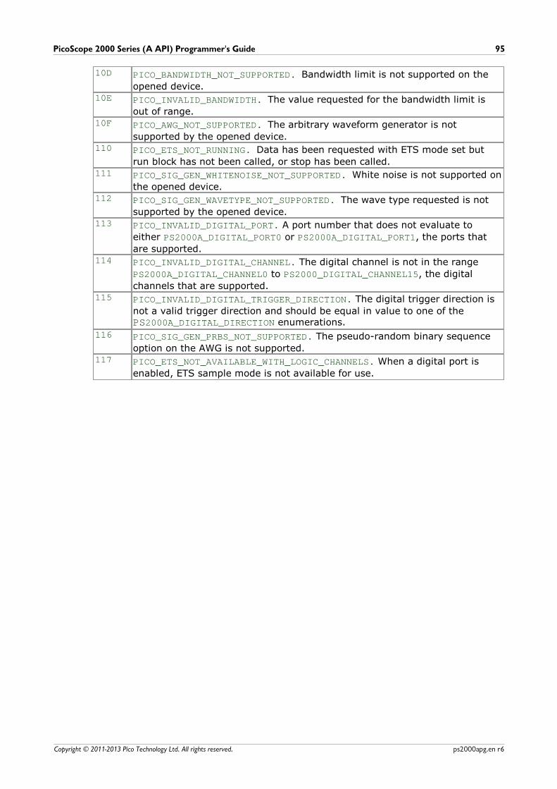
PicoScope 2000 Series (A API) Programmer's Guide 95
Copyright © 2011-2013 Pico Technology Ltd. All rights reserved. ps2000apg.en r6
10D PICO_BANDWIDTH_NOT_SUPPORTED. Bandwidth limit is not supported on the
opened device.10E PICO_INVALID_BANDWIDTH. The value requested for the bandwidth limit is
out of range.10F PICO_AWG_NOT_SUPPORTED. The arbitrary waveform generator is not
supported by the opened device.110 PICO_ETS_NOT_RUNNING. Data has been requested with ETS mode set but
run block has not been called, or stop has been called.111 PICO_SIG_GEN_WHITENOISE_NOT_SUPPORTED. White noise is not supported on
the opened device.112 PICO_SIG_GEN_WAVETYPE_NOT_SUPPORTED. The wave type requested is not
supported by the opened device.113 PICO_INVALID_DIGITAL_PORT. A port number that does not evaluate to
either PS2000A_DIGITAL_PORT0 or PS2000A_DIGITAL_PORT1, the ports that
are supported.114 PICO_INVALID_DIGITAL_CHANNEL. The digital channel is not in the range
PS2000A_DIGITAL_CHANNEL0 to PS2000_DIGITAL_CHANNEL15, the digital
channels that are supported.115 PICO_INVALID_DIGITAL_TRIGGER_DIRECTION. The digital trigger direction is
not a valid trigger direction and should be equal in value to one of the PS2000A_DIGITAL_DIRECTION enumerations.
116 PICO_SIG_GEN_PRBS_NOT_SUPPORTED. The pseudo-random binary sequence
option on the AWG is not supported. 117 PICO_ETS_NOT_AVAILABLE_WITH_LOGIC_CHANNELS. When a digital port is
enabled, ETS sample mode is not available for use.
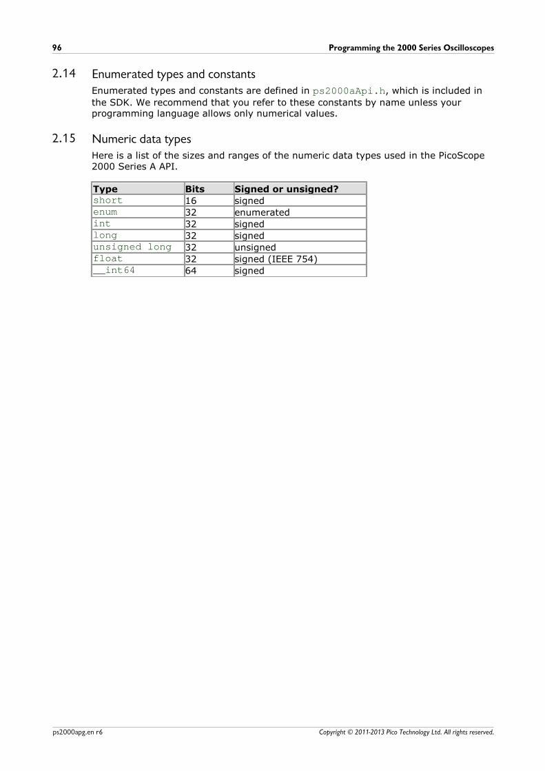
Programming the 2000 Series Oscilloscopes96
Copyright © 2011-2013 Pico Technology Ltd. All rights reserved.ps2000apg.en r6
2.14 Enumerated types and constantsEnumerated types and constants are defined in ps2000aApi.h, which is included in
the SDK. We recommend that you refer to these constants by name unless yourprogramming language allows only numerical values.
2.15 Numeric data typesHere is a list of the sizes and ranges of the numeric data types used in the PicoScope2000 Series A API.
Type Bits Signed or unsigned?short 16 signedenum 32 enumeratedint 32 signedlong 32 signedunsigned long 32 unsignedfloat 32 signed (IEEE 754)__int64 64 signed
PicoScope 2000 Series (A API) Programmer's Guide 97
Copyright © 2011-2013 Pico Technology Ltd. All rights reserved. ps2000apg.en r6
3 GlossaryAC/DC control. Each channel can be set to either AC coupling or DC coupling. WithDC coupling, the voltage displayed on the screen is equal to the true voltage of thesignal. With AC coupling, any DC component of the signal is filtered out, leaving onlythe variations in the signal (the AC component).
Aggregation. This is the data-reduction method used by the PicoScope 2000 Series(A DLL) scopes. For each block of consecutive samples, the scope transmits only theminimum and maximum samples over the USB port to the PC. You can set the numberof samples in each block, called the aggregation parameter, when you call ps2000aRunStreaming for real-time capture, and when you callps2000aGetStreamingLatestValues to obtain post-processed data.
Aliasing. An effect that can cause digital oscilloscopes to display fast-movingwaveforms incorrectly, by showing spurious low-frequency signals ("aliases") that donot exist in the input. To avoid this problem, choose a sampling rate that is at leasttwice the highest frequency in the input signal.
Analog bandwidth. All oscilloscopes have an upper limit to the range of frequenciesat which they can measure accurately. The analog bandwidth of an oscilloscope isdefined as the frequency at which a displayed sine wave has half the power of theinput sine wave (or, equivalently, about 71% of the amplitude).
Block mode. A sampling mode in which the computer prompts the oscilloscope tocollect a block of data into its internal memory before stopping the oscilloscope andtransferring the whole block into computer memory. This mode of operation iseffective when the input signal being sampled contains high frequencies. Note: Toavoid aliasing effects, the maximum input frequency must be less than half thesampling rate.
Buffer size. The size, in samples, of the oscilloscope buffer memory. The buffermemory is used by the oscilloscope to temporarily store data before transferring it tothe PC.
ETS. Equivalent Time Sampling. ETS constructs a picture of a repetitive signal byaccumulating information over many similar wave cycles. This means the oscilloscopecan capture fast-repeating signals that have a higher frequency than the maximumsampling rate. Note: ETS cannot be used for one-shot or non-repetitive signals.
External trigger. This is the BNC socket marked EXT on the oscilloscope. It can beused to start a data collection run but cannot be used to record data.
Maximum sampling rate. A figure indicating the maximum number of samples theoscilloscope is capable of acquiring per second. Maximum sample rates are given inMS/s (megasamples per second) or GS/s (gigasamples per second). The higher thesampling capability of the oscilloscope, the more accurate the representation of thehigh frequencies in a fast signal.
MSO (Mixed signal oscilloscope). An oscilloscope that has both analog and digitalinputs.
Oversampling. Oversampling is taking more than one measurement during a timeinterval and returning an average. If the signal contains a small amount of noise, thistechnique can increase the effective vertical resolution of the oscilloscope.
Glossary98
Copyright © 2011-2013 Pico Technology Ltd. All rights reserved.ps2000apg.en r6
Overvoltage. Any input voltage to the oscilloscope must not exceed the overvoltagelimit, measured with respect to ground, otherwise the oscilloscope may bepermanently damaged.
PC Oscilloscope. A measuring instrument consisting of a Pico Technology scopedevice and the PicoScope software. It provides all the functions of a bench-toposcilloscope without the cost of a display, hard disk, network adapter and othercomponents that your PC already has.
PicoScope software. This is a software product that accompanies all ouroscilloscopes. It turns your PC into an oscilloscope, spectrum analyzer.
Signal generator. This is a feature of some oscilloscopes which allows a signal to begenerated without an external input device being present. The signal generator outputis the BNC socket marked AWG or GEN on the oscilloscope. If you connect a BNCcable between this and one of the channel inputs, you can send a signal into one ofthe channels. It can generate a sine, square, triangle or arbitrary wave of fixed orswept frequency.
Streaming mode. A sampling mode in which the oscilloscope samples data andreturns it to the computer in an unbroken stream. This mode of operation is effectivewhen the input signal being sampled contains only low frequencies.
Timebase. The timebase controls the time interval across the scope display. Thereare ten divisions across the screen and the timebase is specified in units of time perdivision, so the total time interval is ten times the timebase.
USB 1.1—An early version of the Universal Serial Bus standard found on older PCs.Although your PicoScope will work with a USB 1.1 port, it will operate much moreslowly than with a USB 2.0 or 3.0 port.
USB 2.0—Universal Serial Bus (High Speed). A standard port used to connect externaldevices to PCs. The high-speed data connection provided by a USB 2.0 port enablesyour PicoScope to achieve its maximum performance.
USB 3.0—A faster version of the Universal Serial Bus standard. Your PicoScope is fullycompatible with USB 3.0 ports and will operate with the same performance as on aUSB 2.0 port.
Vertical resolution. A value, in bits, indicating the degree of precision with which theoscilloscope can turn input voltages into digital values. Calculation techniques canimprove the effective resolution.
Voltage range. The voltage range is the difference between the maximum andminimum voltages that can be accurately captured by the oscilloscope.
PicoScope 2000 Series (A API) Programmer's Guide 99
Copyright © 2011-2013 Pico Technology Ltd. All rights reserved. ps2000apg.en r6
Index
AAC coupling 60
AC/DC control 97
Access 2
ADC count 48, 50
Address 3
Aggregation 14
Aliasing 97
Analog bandwidth 97
Analog offset 24, 60
API function calls 18
Arbitrary waveform generator 71, 74
BBandwidth limiter 60
Block mode 5, 7, 97
asynchronous call 7
callback 19
polling status 46
running 56
Buffer size 97
CC programming 89
Callback 5, 12
block mode 19
for data 21
streaming mode 88
Channels
enabling 60
settings 60
Closing units 20
Common-mode voltage 97
Communication 55
Connection 55
Constants 96
Contact details 3
Copyright 2
Coupling type, setting 60
DData acquisition 14
Data buffers
declaring 61
declaring, aggregation mode 62
Data retention 5
DC coupling 60
Digital connector 16
Digital data 4
Digital ports 4
Downsampling 5, 37
maximum ratio 26
modes 38
Driver 4
status codes 92
EEmail address 3
Enabling channels 60
Enumerated types 96
Enumerating oscilloscopes 22
ETS
mode 5
overview 12
setting time buffers 65, 66
setting up 64
using 13
Excel macros 89
FFax number 3
Fitness for purpose 2
Function calls 18
Functions
ps2000aBlockReady 19
ps2000aCloseUnit 20
ps2000aDataReady 21
ps2000aEnumerateUnits 22
ps2000aFlashLed 23
ps2000aGetAnalogueOffset 24
ps2000aGetChannelInformation 25
ps2000aGetMaxDownSampleRatio 26
ps2000aGetMaxSegments 27
ps2000aGetNoOfCaptures 28, 29
ps2000aGetStreamingLatestValues 30
ps2000aGetTimebase 16, 31
ps2000aGetTimebase2 32
ps2000aGetTriggerTimeOffset 33
ps2000aGetTriggerTimeOffset64 34
ps2000aGetUnitInfo 35
ps2000aGetValues 7, 37
ps2000aGetValuesAsync 7, 39
ps2000aGetValuesBulk 40
ps2000aGetValuesOverlapped 41
ps2000aGetValuesOverlappedBulk 42
Index100
Copyright © 2011-2013 Pico Technology Ltd. All rights reserved.ps2000apg.en r6
Functions
ps2000aGetValuesTriggerTimeOffsetBulk 43
ps2000aGetValuesTriggerTimeOffsetBulk64 44, 45
ps2000aIsReady 46
ps2000aIsTriggerOrPulseWidthQualifierEnabled 47
ps2000aMaximumValue 4, 48
ps2000aMemorySegments 49
ps2000aMinimumValue 4, 50
ps2000aNoOfStreamingValues 51
ps2000aOpenUnit 52
ps2000aOpenUnitAsync 53
ps2000aOpenUnitProgress 54
ps2000aPingUnit 55
ps2000aRunBlock 56
ps2000aRunStreaming 58
ps2000aSetChannel 4, 60
ps2000aSetDataBuffer 61
ps2000aSetDataBuffers 62
ps2000aSetEts 12, 64
ps2000aSetEtsTimeBuffer 65
ps2000aSetEtsTimeBuffers 66
ps2000aSetNoOfCaptures 67
ps2000aSetPulseWidthQualifier 68
ps2000aSetSigGenArbitrary 71
ps2000aSetSigGenBuiltIn 75
ps2000aSetSimpleTrigger 5, 77
ps2000aSetTriggerChannelConditions 5, 78
ps2000aSetTriggerChannelDirections 5, 80
ps2000aSetTriggerChannelProperties 5, 81
ps2000aSetTriggerDelay 85
ps2000aSetTriggerDigitalPortProperties 83
ps2000aSigGenSoftwareControl 86
ps2000aStop 7, 87
ps2000aStreamingReady 88
HHysteresis 82, 84
IIndex modes
dual 74
single 74
Information, reading from units 35
Input range, selecting 60
Intended use 1
LLabVIEW 89
LED
flashing 23
Legal information 2
Liability 2
MMacros in Excel 89
Memory buffer 5
Memory segmentation 5, 7, 14, 49
Mission-critical applications 2
Multi-unit operation 17
NNumeric data types 96
OOne-shot signals 12
Opening a unit 52
checking progress 54
without blocking 53
Oversampling 38
PPC Oscilloscope 1, 97
PC requirements 1
PICO_STATUS enum type 92
PicoScope 2000 Series 1
PicoScope software 1, 4, 92, 97
PORT0, PORT1 4
Programming
C 89
Excel 89
general procedure 4
LabVIEW 89
ps2000a.dll 4
PS2000A_CONDITION_ constants 70, 79
PS2000A_LEVEL constant 82, 84
PS2000A_PWQ_CONDITIONS structure 70
PS2000A_RATIO_MODE_AGGREGATE 38
PS2000A_RATIO_MODE_AVERAGE 38
PS2000A_RATIO_MODE_DECIMATE 38
PS2000A_TIME_UNITS constant 33, 34
PS2000A_TRIGGER_CHANNEL_PROPERTIESstructure 82, 84
PS2000A_TRIGGER_CONDITIONS 78
PS2000A_TRIGGER_CONDITIONS structure 79
PS2000A_WINDOW constant 82, 84
Pulse-width qualifier 68
conditions 70
PicoScope 2000 Series (A API) Programmer's Guide 101
Copyright © 2011-2013 Pico Technology Ltd. All rights reserved. ps2000apg.en r6
Pulse-width qualifier 68
requesting status 47
RRanges 25
Rapid block mode 5, 8, 28, 29
aggregation 11
no aggregation 9
setting number of captures 67
Resolution, vertical 97
Retrieving data 37, 39
block mode, deferred 41
rapid block mode 40
rapid block mode, deferred 42
stored 15
streaming mode 30
Retrieving times
rapid block mode 43, 44, 45
SSampling rate 97
maximum 5
Scaling 4
Serial numbers 22
Setup time 5
Signal generator
arbitrary waveforms 71
built-in waveforms 75
software trigger 86
Status codes 92
Stopping sampling 87
Streaming mode 5, 14, 97
callback 88
getting number of samples 51
retrieving data 30
running 58
using 15
Support 2
TTechnical assistance 3
Telephone number 3
Threshold voltage 5
Time buffers
setting for ETS 65, 66
Timebase 16, 97
calculating 31, 32
Trademarks 2
Trigger 5
channel properties 81, 83
conditions 78, 79
delay 85
digital ports 83
directions 80
pulse-width qualifier 68
pulse-width qualifier conditions 70
requesting status 47
setting up 77
stability 12
time offset 33, 34
UUpgrades 2
Usage 2
USB 1, 4, 97
hub 17
VViruses 2
Voltage range 4, 97
selecting 60
WWebsite address 3
WinUsb.sys 4


PicoScope 2000 Series (A API) Programmer's Guide 103
Copyright © 2011-2013 Pico Technology Ltd. All rights reserved. ps2000apg.en r6
Pico TechnologyJames House
Colmworth Business ParkST. NEOTS
CambridgeshirePE19 8YP
United KingdomTel: +44 (0) 1480 396 395Fax: +44 (0) 1480 396 296
www.picotech.com
Copyright © 2011-2013 Pico Technology Ltd. All rights reserved.ps2000apg.en r6 13.08.13