Embed Size (px)
Citation preview
Microvision, Inc. Proprietary & Confidential Page 1 of 46
PicoP® Display Engine (PDE)Programmer’s Guide
Document Number DC0127564Revision B.118-June-2012
PicoP® Display Engine (PDE) Programmer’s Guide
DC0127564 Revision: B.1 Revision Date: 18-June-2012
Copyright© Microvision, Inc., 2010 Page 2 of 46
IMPORTANT NOTICE
1. All design and engineering decisions with regard to the integration of PicoP® DisplayEngine (PDE) module inside the customer’s products are the responsibility of thecustomer. This includes all decisions related to the application of PDE, including anybeam redirection and/or manipulation provided external to the PDE module or anydecisions that may affect the laser classification of customer’s products.
2. This PicoP® Display Engine (PDE) Programmer’s Guide is confidential and proprietaryinformation of Microvision and the information contained herein may not be sharedwith any third party (individual or entity) without express written permission fromMicrovision. This document and the information contained herein is MicrovisionConfidential Information subject to the terms and conditions of the Non-DisclosureAgreement between Microvision and customer.
PicoP® Display Engine (PDE) Programmer’s Guide
DC0127564 Revision: B.1 Revision Date: 18-June-2012
Copyright© Microvision, Inc., 2010 Page 3 of 46
1. Scope............................................................................................................................................................... 51.1. Reference................................................................................................................................................. 6
2. Communication Interface................................................................................................................................ 73. API Functions.................................................................................................................................................. 8
3.1. API Version Information......................................................................................................................... 83.1.1. GetLibraryInfo ( libraryInfo) .......................................................................................................... 8
3.2. Connection Management Functions........................................................................................................ 83.2.1. OpenLibrary ( libraryHandle) ......................................................................................................... 83.2.2. CloseLibrary ( libraryHandle) ......................................................................................................... 83.2.3. OpenConnection ( connectionType, connectionInfo, connectionHandle) ...................................... 83.2.4. CloseConnection ( connectionHandle)............................................................................................ 93.2.5. EnumerateDevices (numDevicesToEnumerate,NumDevices,DeviceInfo)..................................... 93.2.6. OpenConnectionUSB (connectionInfo, connectionHandle) ........................................................... 93.2.7. OpenConnectionRS232 (connectionInfo, connectionHandle) ........................................................ 9
3.3. Display Control Functions .................................................................................................................... 103.3.1. SetOutputVideoState ( state,commit)............................................................................................ 103.3.2. GetOutputVideoState ( state,type) ................................................................................................ 103.3.3. SetBrightnessVal ( brightness, commit)........................................................................................ 103.3.4. GetBrightnessVal ( brightness, type) ............................................................................................ 103.3.5. SetColorMode ( colorMode, commit) ........................................................................................... 123.3.6. GetColorMode ( colorMode, type)................................................................................................ 123.3.7. SetAspectRatio ( aspectRatio, commit)......................................................................................... 133.3.8. GetAspectRatio ( aspectRatio, type) ............................................................................................. 143.3.9. SetGammaVal ( color, gammaVal, commit)................................................................................. 143.3.10. GetGammaVal ( color, gammaVal, type) ..................................................................................... 163.3.11. FlipImage ( direction).................................................................................................................... 163.3.12. SetFlipState(flipState,commit) ...................................................................................................... 173.3.13. GetFlipState(flipState,type)........................................................................................................... 173.3.14. CorrectKeystone ( keystoneCorrectionVal, commit) ................................................................... 183.3.15. GetKeystoneCorrection ( keystoneCorrectionVal, type) .............................................................. 183.3.16. SetupWarp ( scrSize, destSize, commit) ....................................................................................... 193.3.17. GetWarpSetup (scrSize, destSize,type)......................................................................................... 193.3.18. WarpImage ( warpOperation, value, commit)............................................................................... 203.3.19. GetWarpParameter ( warpOperation,value,type)......................................................................... 213.3.20. SetWarpState(state, commit)......................................................................................................... 223.3.21. GetWarpState ( type, state ) .......................................................................................................... 223.3.22. SetOutputVideoState( state,commit)............................................................................................. 223.3.23 GetOutputVideoState ( state)........................................................................................................ 223.3.24 SetColorConverter ( color, coefficient, commit )............................................................................... 233.3.25. GetColorConverter ( color, coefficient, type ) .............................................................................. 233.3.26. SetPhase ( phaseOffset, commit) .................................................................................................. 243.3.27. GetPhase ( phaseOffset, type) ....................................................................................................... 253.3.28. SetColorAlignment ( direction, color, offset, commit ) ................................................................ 253.3.29. GetColorAlignment ( direction, color, offset, type ) ..................................................................... 263.3.30. AutoSetGreenMagentaBalance ( )................................................................................................. 263.3.31. GetAutoGreenMagentaBalanceStatus ( ) ...................................................................................... 263.3.32. SetGreenMagentaBalance ( offset, commit ) ................................................................................ 263.3.33. GetGreenMagentaBalance ( offset, type) ...................................................................................... 273.3.34. SetViewportDistortion (distortion value, commit)........................................................................ 273.3.35. GetViewportDistortion (distortion value, type) ............................................................................ 283.3.36. SetOutputVideoStateEx (state, commit) ....................................................................................... 28
PicoP® Display Engine (PDE) Programmer’s Guide
DC0127564 Revision: B.1 Revision Date: 18-June-2012
Copyright© Microvision, Inc., 2010 Page 4 of 46
3.3.37. GetOutputVideoStateEx (state, type) ............................................................................................ 283.3.38. SetSplashScreenTimeout (timeout value, commit) ....................................................................... 293.3.39. GetSplashScreenTimeout (timeout value, type)............................................................................ 293.3.40. SetVerticalProjectionAngleOffset (offset value, commit) ............................................................ 293.3.41. GetVerticalProjectionAngleOffset (offset value, type)................................................................. 30
3.4. Input Control Functions ........................................................................................................................ 313.4.1. SetInputVideoState ( state)............................................................................................................ 313.4.2. GetInputVideoState ( state) ........................................................................................................... 313.4.3. SetInputCaptureModeInfo ( modeHandle, captureInfo) ............................................................... 313.4.4. ModifyInputCaptureModeInfo ( modeHandle, captureInfo) ........................................................ 323.4.5. CommitCaptureModeInfo ( modeHandle) .................................................................................... 323.4.6. GetCommitedInputCaptureMode ( modeHandle)......................................................................... 323.4.7. GetInputCaptureModeInfo ( modeHandle, captureInfo)............................................................... 323.4.8. SetActiveCaptureMode ( modeHandle) ........................................................................................ 333.4.9. GetActiveCaptureMode ( modeHandle) ....................................................................................... 333.4.10. GetInputVideoProperties ( frameRate, lines ) ............................................................................... 33
3.5. Rendering Functions ............................................................................................................................. 343.5.1. SetOSDState ( state)...................................................................................................................... 343.5.2. GetOSDState ( state) ..................................................................................................................... 343.5.3. SetOSDInfo ( startPoint, size ) ..................................................................................................... 343.5.4. GetOSDInfo ( startPoint, size) ...................................................................................................... 353.5.5. GetDisplayInfo ( renderTarget, size )............................................................................................ 353.5.6. SetActiveFrameBuffer ( renderTarget ) ........................................................................................ 353.5.7. GetActiveFrameBuffer ( renderTarget )........................................................................................ 353.5.8. LoadBitmapImage (target, startPoint, dimensions, imageBuf, bufLength ) ................................ 363.5.9. DrawTestPattern ( target, startPoint, dimensions, patternColor, backgroundColor, pattern)........ 373.5.10. DrawText ( target, text, length, location, color ) ........................................................................... 393.5.11. GetTextBoxInfo ( text, length, textBoxRegion )........................................................................... 393.5.12. DrawPoint ( target, pixel, color).................................................................................................... 393.5.13. DrawLine ( target, pointA, pointB, color ).................................................................................... 403.5.14. DrawTriangle (target, pointA, pointB, pointC, fillColor) ............................................................. 403.5.15. DrawRectangle ( target, startPoint, size, fillColor) ....................................................................... 413.5.16. Render ( target).............................................................................................................................. 41
3.6. System Management Functions ............................................................................................................ 433.6.1. GetSystemStatus ( systemStatus) .................................................................................................. 433.6.2. GetSystemInfo ( systemInfo) ........................................................................................................ 443.6.3. GetEventLog ( numEvents, events) .............................................................................................. 443.6.4. SetSystemPowerState ( state)........................................................................................................ 443.6.5. GetSystemPowerState ( state) ....................................................................................................... 453.6.6. RestoreFactoryConfig (commit) ................................................................................................... 453.6.7. SaveSplashScreen ( target)............................................................................................................ 453.6.8. UpgradeSoftware (image, size) ..................................................................................................... 453.6.9. UpgradeSoftware_Ex (image, size, callback) ............................................................................... 45
PicoP® Display Engine (PDE) Programmer’s Guide
DC0127564 Revision: B.1 Revision Date: 18-June-2012
Copyright© Microvision, Inc., 2010 Page 5 of 46
1. ScopeThis document details the command and control interface of Microvision’s PicoP® Display Engine (PDE).
The PDE is intended to be used by customers wishing to embed a small and thin full color laser projector insidetheir product. The PDE comes with PicoP® Software Development Kits (SDKs), which facilitate third-partyApplication Software development for the PicoP Display Engine (PDE).
The PicoP SDKs contain the following:
Operating System specific software libraries for interfacing with the PDE
Application Programming Interfaces (APIs)
Sample Applications
Documentation
The PicoP SDKs support 3 API types:
C Function API for the Windows operating system and Linux operating system
Java Class API for Android ™ operating system
Objective-C Class API for iPhone OS (Requires external iPhone OS Authentication Hardware)
Other languages in the Windows and Linux operating systems, such as Java, C#, or VB.Net can be supportedthrough wrappers or controls built on top of the C Function API.
This document defines all applicable functions and commands supported by the PDE ApplicationProgramming Interface (API). The supported functions are described in programming language independentpseudo-code. For language specific information, please refer to the appropriate PDE Software Development Kit(SDK) documentation.
The information contained in this document is provided for guidance purposes only and is subject tochange.
PicoP® Display Engine (PDE) Programmer’s Guide
DC0127564 Revision: B.1 Revision Date: 18-June-2012
Copyright© Microvision, Inc., 2010 Page 6 of 46
1.1. ReferenceDA0127245 - PicoP® Windows SDK Getting Started Guide
DA0127249 - PicoP® Windows SDK Programmer's Reference Guide
DA0127254 - PicoP® Linux SDK Getting Started Guide
DA0127256 - PicoP® Linux SDK Programmer's Reference Guide
DA0130542 - PicoP Mac OS X SDK Getting Started Guide
DA0130544 - PicoP Mac OS X SDK Programmer's Reference Guide
DA0127268 - PicoP® Android SDK Getting Started Guide
DA0127270 - PicoP® Android SDK Programmer's Reference Guide
DA0128984 - PicoP Ångström Linux SDK Getting Started Guide
DA0128986 - PicoP Ångström Linux SDK Programmer's Reference Guide
DA0127261 - PicoP® iPhone OS SDK Getting Started Guide
DA0127263 - PicoP® iPhone OS SDK Programmer's Reference Guide
DA0129161 - PicoP® µC SDK Getting Started Guide
DA0129163 - PicoP® µC SDK Programmer's Reference Guide
DC0125698 - PDE Specification & Interface Control Document
PicoP® Display Engine (PDE) Programmer’s Guide
DC0127564 Revision: B.1 Revision Date: 18-June-2012
Copyright© Microvision, Inc., 2010 Page 7 of 46
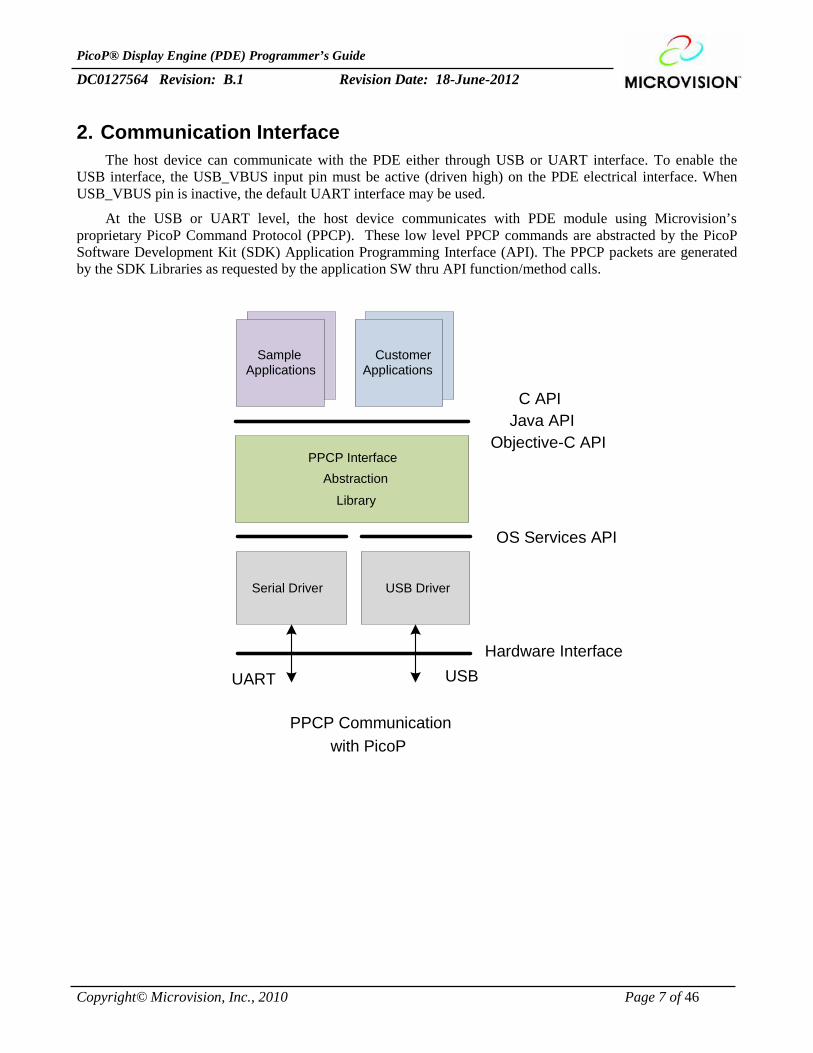
2. Communication InterfaceThe host device can communicate with the PDE either through USB or UART interface. To enable the
USB interface, the USB_VBUS input pin must be active (driven high) on the PDE electrical interface. WhenUSB_VBUS pin is inactive, the default UART interface may be used.
At the USB or UART level, the host device communicates with PDE module using Microvision’sproprietary PicoP Command Protocol (PPCP). These low level PPCP commands are abstracted by the PicoPSoftware Development Kit (SDK) Application Programming Interface (API). The PPCP packets are generatedby the SDK Libraries as requested by the application SW thru API function/method calls.
Serial Driver USB Driver
PPCP Communicationwith PicoP
PPCP InterfaceAbstraction
SampleApplications
CustomerApplications
C API
Objective-C APIJava API
OS Services API
Library
UART USBHardware Interface
PicoP® Display Engine (PDE) Programmer’s Guide
DC0127564 Revision: B.1 Revision Date: 18-June-2012
Copyright© Microvision, Inc., 2010 Page 8 of 46
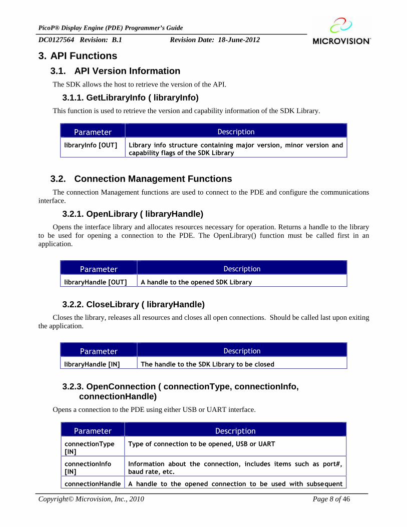
3. API Functions3.1. API Version InformationThe SDK allows the host to retrieve the version of the API.
3.1.1. GetLibraryInfo ( libraryInfo)This function is used to retrieve the version and capability information of the SDK Library.
Parameter Description
libraryInfo [OUT] Library info structure containing major version, minor version andcapability flags of the SDK Library
3.2. Connection Management FunctionsThe connection Management functions are used to connect to the PDE and configure the communications
interface.
3.2.1. OpenLibrary ( libraryHandle)Opens the interface library and allocates resources necessary for operation. Returns a handle to the library
to be used for opening a connection to the PDE. The OpenLibrary() function must be called first in anapplication.
Parameter Description
libraryHandle [OUT] A handle to the opened SDK Library
3.2.2. CloseLibrary ( libraryHandle)Closes the library, releases all resources and closes all open connections. Should be called last upon exiting
the application.
Parameter Description
libraryHandle [IN] The handle to the SDK Library to be closed
3.2.3. OpenConnection ( connectionType, connectionInfo,connectionHandle)
Opens a connection to the PDE using either USB or UART interface.
Parameter Description
connectionType[IN]
Type of connection to be opened, USB or UART
connectionInfo[IN]
Information about the connection, includes items such as port#,baud rate, etc.
connectionHandle A handle to the opened connection to be used with subsequent
PicoP® Display Engine (PDE) Programmer’s Guide
DC0127564 Revision: B.1 Revision Date: 18-June-2012
Copyright© Microvision, Inc., 2010 Page 9 of 46
[OUT] function calls
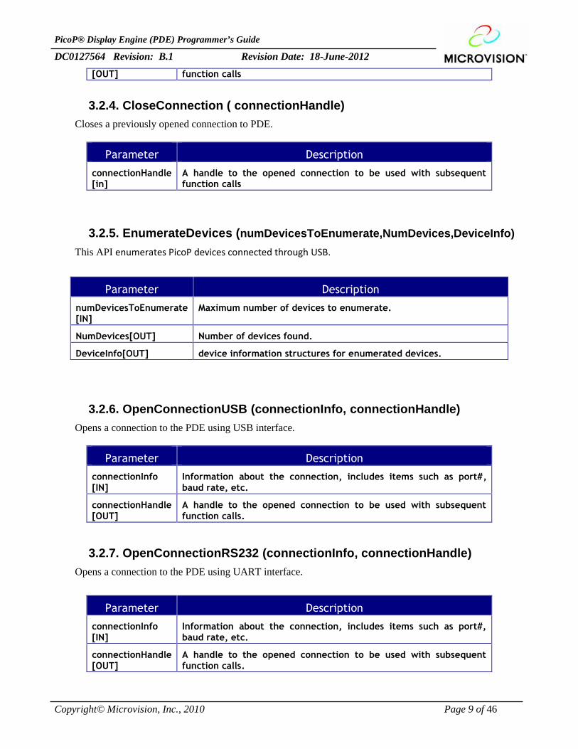
3.2.4. CloseConnection ( connectionHandle)Closes a previously opened connection to PDE.
Parameter Description
connectionHandle[in]
A handle to the opened connection to be used with subsequentfunction calls
3.2.5. EnumerateDevices (numDevicesToEnumerate,NumDevices,DeviceInfo)This API enumerates PicoP devices connected through USB.
Parameter Description
numDevicesToEnumerate[IN]
Maximum number of devices to enumerate.
NumDevices[OUT] Number of devices found.
DeviceInfo[OUT] device information structures for enumerated devices.
3.2.6. OpenConnectionUSB (connectionInfo, connectionHandle)Opens a connection to the PDE using USB interface.
Parameter Description
connectionInfo[IN]
Information about the connection, includes items such as port#,baud rate, etc.
connectionHandle[OUT]
A handle to the opened connection to be used with subsequentfunction calls.
3.2.7. OpenConnectionRS232 (connectionInfo, connectionHandle)Opens a connection to the PDE using UART interface.
Parameter Description
connectionInfo[IN]
Information about the connection, includes items such as port#,baud rate, etc.
connectionHandle[OUT]
A handle to the opened connection to be used with subsequentfunction calls.
PicoP® Display Engine (PDE) Programmer’s Guide
DC0127564 Revision: B.1 Revision Date: 18-June-2012
Copyright© Microvision, Inc., 2010 Page 10 of 46
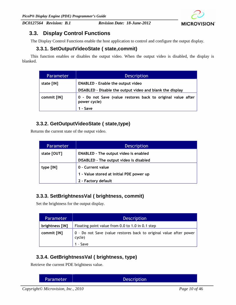
3.3. Display Control FunctionsThe Display Control Functions enable the host application to control and configure the output display.
3.3.1. SetOutputVideoState ( state,commit)This function enables or disables the output video. When the output video is disabled, the display is
blanked.
Parameter Description
state [IN] ENABLED – Enable the output video
DISABLED – Disable the output video and blank the display
commit [IN] 0 – Do not Save (value restores back to original value afterpower cycle)
1 – Save
3.3.2. GetOutputVideoState ( state,type)Returns the current state of the output video.
Parameter Description
state [OUT] ENABLED – The output video is enabled
DISABLED – The output video is disabled
type [IN] 0 – Current value
1 – Value stored at initial PDE power up
2 – Factory default
3.3.3. SetBrightnessVal ( brightness, commit)Set the brightness for the output display.
Parameter Description
brightness [IN] Floating point value from 0.0 to 1.0 in 0.1 step
commit [IN] 0 – Do not Save (value restores back to original value after powercycle)
1 – Save
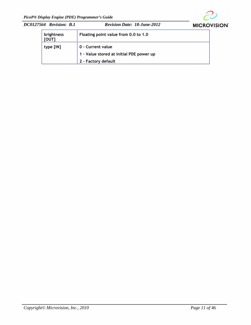
3.3.4. GetBrightnessVal ( brightness, type)Retrieve the current PDE brightness value.
Parameter Description
PicoP® Display Engine (PDE) Programmer’s Guide
DC0127564 Revision: B.1 Revision Date: 18-June-2012
Copyright© Microvision, Inc., 2010 Page 11 of 46
brightness[OUT]
Floating point value from 0.0 to 1.0
type [IN] 0 – Current value
1 – Value stored at initial PDE power up
2 – Factory default
PicoP® Display Engine (PDE) Programmer’s Guide
DC0127564 Revision: B.1 Revision Date: 18-June-2012
Copyright© Microvision, Inc., 2010 Page 12 of 46
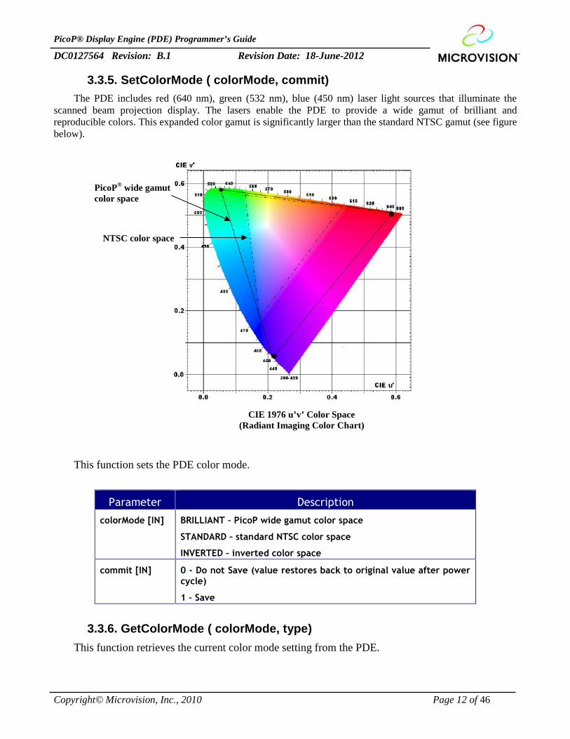
3.3.5. SetColorMode ( colorMode, commit)The PDE includes red (640 nm), green (532 nm), blue (450 nm) laser light sources that illuminate the
scanned beam projection display. The lasers enable the PDE to provide a wide gamut of brilliant andreproducible colors. This expanded color gamut is significantly larger than the standard NTSC gamut (see figurebelow).
This function sets the PDE color mode.
Parameter Description
colorMode [IN] BRILLIANT – PicoP wide gamut color space
STANDARD – standard NTSC color space
INVERTED – inverted color space
commit [IN] 0 – Do not Save (value restores back to original value after powercycle)
1 – Save
3.3.6. GetColorMode ( colorMode, type)This function retrieves the current color mode setting from the PDE.
PicoP® wide gamutcolor space
NTSC color space
CIE 1976 u’v’ Color Space(Radiant Imaging Color Chart)
PicoP® Display Engine (PDE) Programmer’s Guide
DC0127564 Revision: B.1 Revision Date: 18-June-2012
Copyright© Microvision, Inc., 2010 Page 13 of 46
Parameter Description
colorMode [OUT] BRILLIANT – PicoP wide gamut color space
STANDARD – standard NTSC color space
INVERTED – inverted color space
type [IN] 0 – Current value
1 – Value stored at initial PDE power up
2 – Factory default
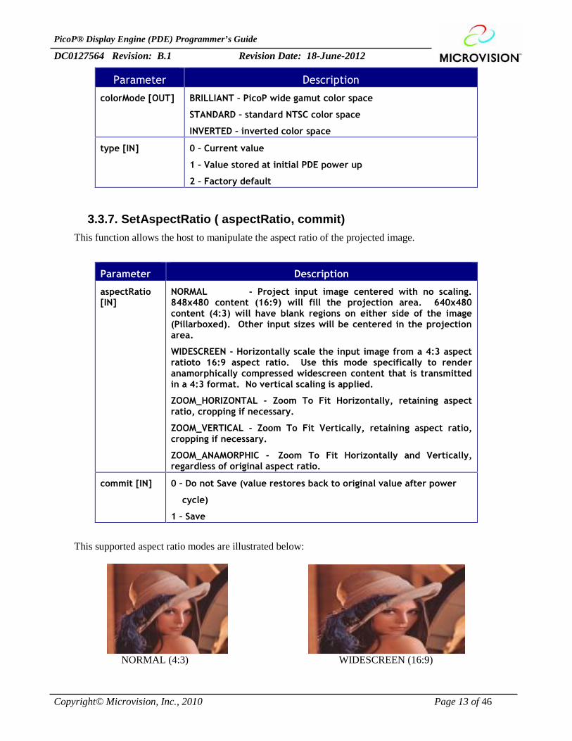
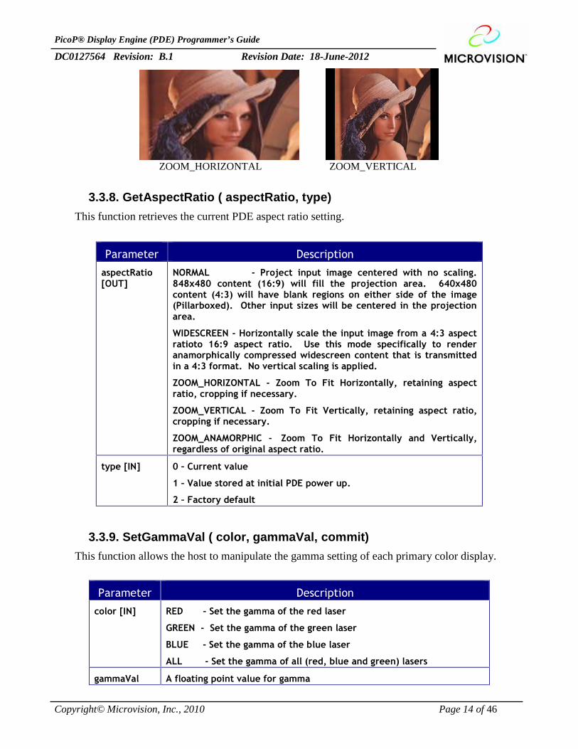
3.3.7. SetAspectRatio ( aspectRatio, commit)This function allows the host to manipulate the aspect ratio of the projected image.
Parameter Description
aspectRatio[IN]
NORMAL - Project input image centered with no scaling.848x480 content (16:9) will fill the projection area. 640x480content (4:3) will have blank regions on either side of the image(Pillarboxed). Other input sizes will be centered in the projectionarea.
WIDESCREEN - Horizontally scale the input image from a 4:3 aspectratioto 16:9 aspect ratio. Use this mode specifically to renderanamorphically compressed widescreen content that is transmittedin a 4:3 format. No vertical scaling is applied.
ZOOM_HORIZONTAL - Zoom To Fit Horizontally, retaining aspectratio, cropping if necessary.
ZOOM_VERTICAL - Zoom To Fit Vertically, retaining aspect ratio,cropping if necessary.
ZOOM_ANAMORPHIC - Zoom To Fit Horizontally and Vertically,regardless of original aspect ratio.
commit [IN] 0 – Do not Save (value restores back to original value after power
cycle)
1 – Save
This supported aspect ratio modes are illustrated below:
NORMAL (4:3) WIDESCREEN (16:9)
PicoP® Display Engine (PDE) Programmer’s Guide
DC0127564 Revision: B.1 Revision Date: 18-June-2012
Copyright© Microvision, Inc., 2010 Page 14 of 46
ZOOM_HORIZONTAL ZOOM_VERTICAL
3.3.8. GetAspectRatio ( aspectRatio, type)This function retrieves the current PDE aspect ratio setting.
Parameter Description
aspectRatio[OUT]
NORMAL - Project input image centered with no scaling.848x480 content (16:9) will fill the projection area. 640x480content (4:3) will have blank regions on either side of the image(Pillarboxed). Other input sizes will be centered in the projectionarea.
WIDESCREEN - Horizontally scale the input image from a 4:3 aspectratioto 16:9 aspect ratio. Use this mode specifically to renderanamorphically compressed widescreen content that is transmittedin a 4:3 format. No vertical scaling is applied.
ZOOM_HORIZONTAL - Zoom To Fit Horizontally, retaining aspectratio, cropping if necessary.
ZOOM_VERTICAL - Zoom To Fit Vertically, retaining aspect ratio,cropping if necessary.
ZOOM_ANAMORPHIC - Zoom To Fit Horizontally and Vertically,regardless of original aspect ratio.
type [IN] 0 – Current value
1 – Value stored at initial PDE power up.
2 – Factory default
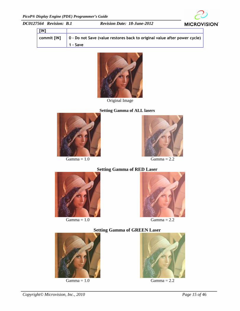
3.3.9. SetGammaVal ( color, gammaVal, commit)This function allows the host to manipulate the gamma setting of each primary color display.
Parameter Description
color [IN] RED – Set the gamma of the red laser
GREEN - Set the gamma of the green laser
BLUE - Set the gamma of the blue laser
ALL - Set the gamma of all (red, blue and green) lasers
gammaVal A floating point value for gamma
PicoP® Display Engine (PDE) Programmer’s Guide
DC0127564 Revision: B.1 Revision Date: 18-June-2012
Copyright© Microvision, Inc., 2010 Page 15 of 46
[IN]
commit [IN] 0 – Do not Save (value restores back to original value after power cycle)
1 – Save
Original Image
Setting Gamma of ALL lasers
Gamma = 1.0 Gamma = 2.2
Setting Gamma of RED Laser
Gamma = 1.0 Gamma = 2.2
Setting Gamma of GREEN Laser
Gamma = 1.0 Gamma = 2.2
PicoP® Display Engine (PDE) Programmer’s Guide
DC0127564 Revision: B.1 Revision Date: 18-June-2012
Copyright© Microvision, Inc., 2010 Page 16 of 46
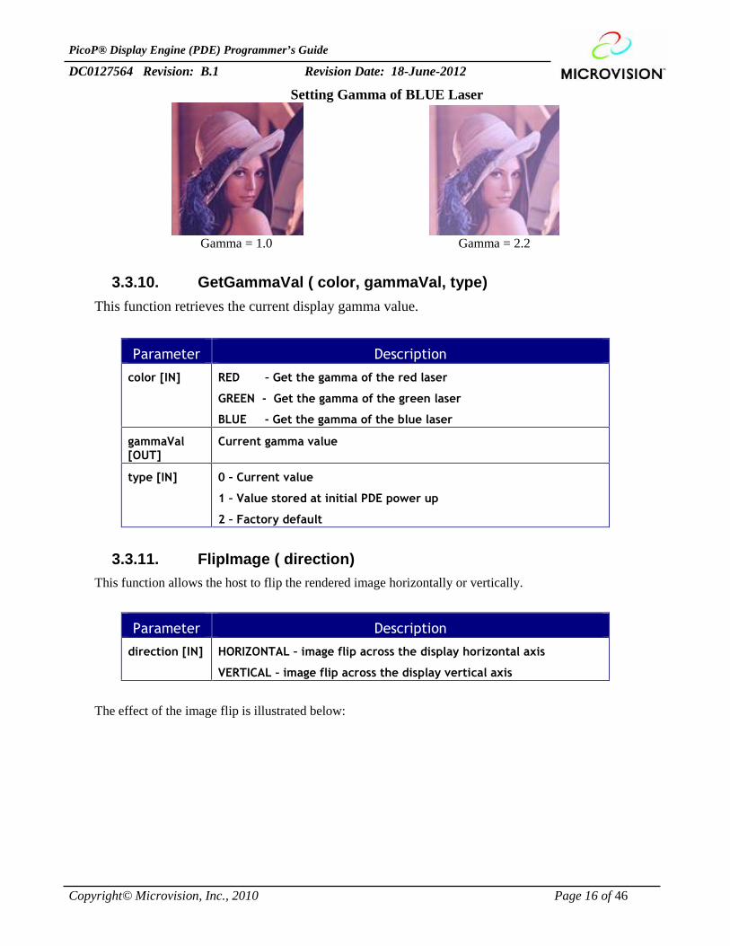
Setting Gamma of BLUE Laser
Gamma = 1.0 Gamma = 2.2
3.3.10. GetGammaVal ( color, gammaVal, type)This function retrieves the current display gamma value.
Parameter Description
color [IN] RED – Get the gamma of the red laser
GREEN - Get the gamma of the green laser
BLUE - Get the gamma of the blue laser
gammaVal[OUT]
Current gamma value
type [IN] 0 – Current value
1 – Value stored at initial PDE power up
2 – Factory default
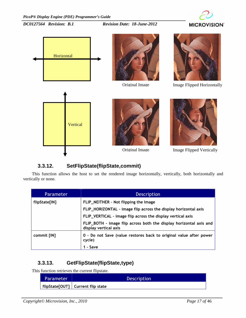
3.3.11. FlipImage ( direction)This function allows the host to flip the rendered image horizontally or vertically.
Parameter Description
direction [IN] HORIZONTAL – image flip across the display horizontal axis
VERTICAL – image flip across the display vertical axis
The effect of the image flip is illustrated below:
PicoP® Display Engine (PDE) Programmer’s Guide
DC0127564 Revision: B.1 Revision Date: 18-June-2012
Copyright© Microvision, Inc., 2010 Page 17 of 46
3.3.12. SetFlipState(flipState,commit)This function allows the host to set the rendered image horizontally, vertically, both horizontally and
vertically or none.
Parameter Description
flipState[IN] FLIP_NEITHER – Not flipping the Image
FLIP_HORIZONTAL – image flip across the display horizontal axis
FLIP_VERTICAL – image flip across the display vertical axis
FLIP_BOTH - image flip across both the display horizontal axis anddisplay vertical axis
commit [IN] 0 – Do not Save (value restores back to original value after powercycle)
1 – Save
3.3.13. GetFlipState(flipState,type)This function retrieves the current flipstate.
Parameter Description
flipState[OUT] Current flip state
Image Flipped HorizontallyOriginal Image
Horizontal
Image Flipped VerticallyOriginal Image
Vertical
PicoP® Display Engine (PDE) Programmer’s Guide
DC0127564 Revision: B.1 Revision Date: 18-June-2012
Copyright© Microvision, Inc., 2010 Page 18 of 46
type [IN] 0 – Current value
1 – Value stored at initial PDE power up
2 – Factory default
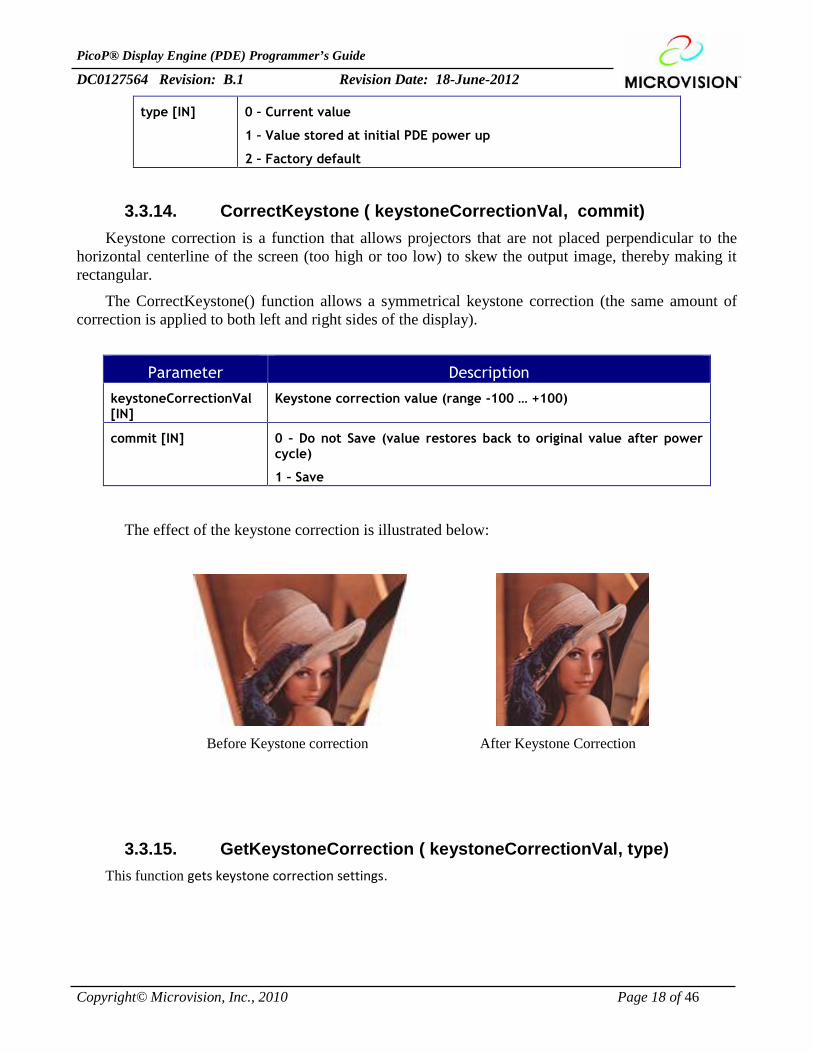
3.3.14. CorrectKeystone ( keystoneCorrectionVal, commit)Keystone correction is a function that allows projectors that are not placed perpendicular to the
horizontal centerline of the screen (too high or too low) to skew the output image, thereby making itrectangular.
The CorrectKeystone() function allows a symmetrical keystone correction (the same amount ofcorrection is applied to both left and right sides of the display).
Parameter Description
keystoneCorrectionVal[IN]
Keystone correction value (range -100 … +100)
commit [IN] 0 – Do not Save (value restores back to original value after powercycle)
1 – Save
The effect of the keystone correction is illustrated below:
Before Keystone correction After Keystone Correction
3.3.15. GetKeystoneCorrection ( keystoneCorrectionVal, type)This function gets keystone correction settings.
PicoP® Display Engine (PDE) Programmer’s Guide
DC0127564 Revision: B.1 Revision Date: 18-June-2012
Copyright© Microvision, Inc., 2010 Page 19 of 46
Parameter Description
keystoneCorrectionVal[OUT]
Keystone correction value (range -100 … +100)
type [IN] 0 – Current value
1 – Value stored at initial PDE power up
2 – Factory default
3.3.16. SetupWarp ( scrSize, destSize, commit)This function sets up the PDE Warp engine by providing the size of the source area to be warped
and destination area to display the results.
Parameter Description
scrSize [IN] Size (Width and Heigth) of the display source area
destSize [IN] Size (Width and Heigth) of the display destination area
commit [IN] 0 – Do not Save (value restores back to original value afterpower cycle)
1 – Save
3.3.17. GetWarpSetup (scrSize, destSize,type)This function gets the size of the source area to be warped and destination area to display the
results.
Parameter Description
scrSize [OUT] Size (Width and Heigth) of the display source area
destSize [OUT] Size (Width and Heigth) of the display destination area
type [IN] 0 – Current value
1 – Value stored at initial PDE power up
2 – Factory default
PicoP® Display Engine (PDE) Programmer’s Guide
DC0127564 Revision: B.1 Revision Date: 18-June-2012
Copyright© Microvision, Inc., 2010 Page 20 of 46
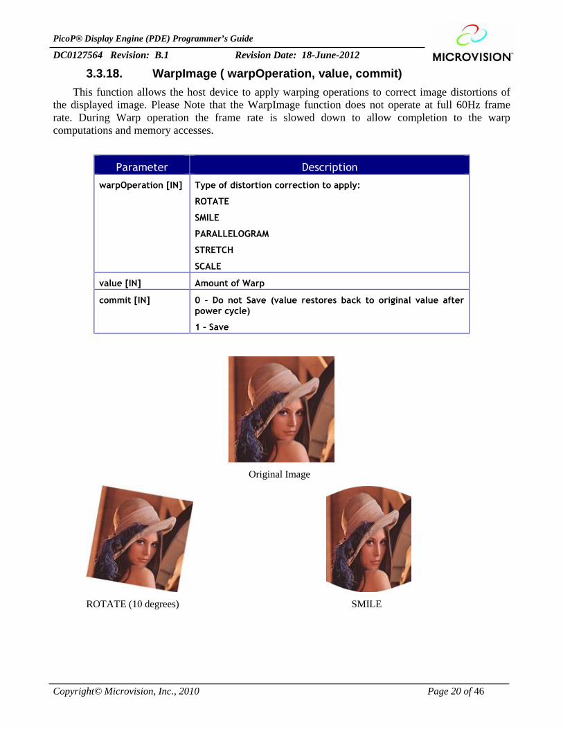
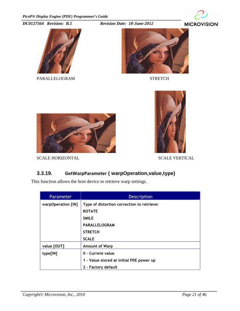
3.3.18. WarpImage ( warpOperation, value, commit)This function allows the host device to apply warping operations to correct image distortions of
the displayed image. Please Note that the WarpImage function does not operate at full 60Hz framerate. During Warp operation the frame rate is slowed down to allow completion to the warpcomputations and memory accesses.
Parameter Description
warpOperation [IN] Type of distortion correction to apply:
ROTATE
SMILE
PARALLELOGRAM
STRETCH
SCALE
value [IN] Amount of Warp
commit [IN] 0 – Do not Save (value restores back to original value afterpower cycle)
1 – Save
Original Image
ROTATE (10 degrees) SMILE
PicoP® Display Engine (PDE) Programmer’s Guide
DC0127564 Revision: B.1 Revision Date: 18-June-2012
Copyright© Microvision, Inc., 2010 Page 21 of 46
PARALLELOGRAM STRETCH
SCALE HORIZONTAL SCALE VERTICAL
3.3.19. GetWarpParameter ( warpOperation,value,type)This function allows the host device to retrieve warp settings.
Parameter Description
warpOperation [IN] Type of distortion correction to retrieve:
ROTATE
SMILE
PARALLELOGRAM
STRETCH
SCALE
value [OUT] Amount of Warp
type[IN] 0 – Current value
1 – Value stored at initial PDE power up
2 – Factory default
PicoP® Display Engine (PDE) Programmer’s Guide
DC0127564 Revision: B.1 Revision Date: 18-June-2012
Copyright© Microvision, Inc., 2010 Page 22 of 46
3.3.20. SetWarpState(state, commit)This function enables or disables the warp operation of the output display.
Parameter Description
state [IN] ENABLED – Enable the warp operation.
DISABLED – Disable the warp operation.
commit [IN] 0 – Do not Save (value restores back to original value afterpower cycle)
1 – Save
3.3.21. GetWarpState ( type, state )This function returns the current warp state of the output display.
Parameter Description
type [IN] 0 – Current value
1 – Value stored at initial PDE power up
2 – Factory default
state [OUT] Current warp state.
3.3.22. SetOutputVideoState( state,commit)This function enables or disables the output video. When output video is disabled, the display is blanked.
Parameter Description
state [IN] ENABLED – The output video is enabled.
DISABLED – The output video is disabled.
commit [IN] 0 – Do not Save (value restores back to original value afterpower cycle)
1 – Save
3.3.23 GetOutputVideoState ( state)This fuction gets the state of the output video.
Parameter Description
state [OUT] ENABLED – The output video is enabled.
DISABLED – The output video is disabled.
PicoP® Display Engine (PDE) Programmer’s Guide
DC0127564 Revision: B.1 Revision Date: 18-June-2012
Copyright© Microvision, Inc., 2010 Page 23 of 46
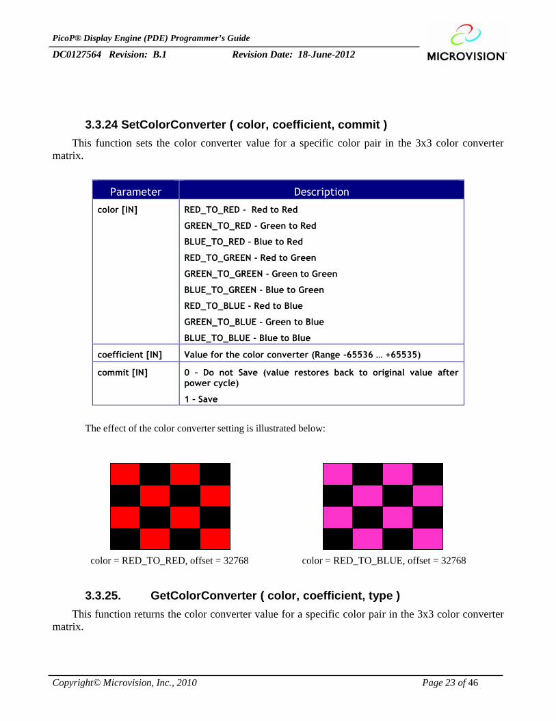
3.3.24 SetColorConverter ( color, coefficient, commit )This function sets the color converter value for a specific color pair in the 3x3 color converter
matrix.
Parameter Description
color [IN] RED_TO_RED - Red to Red
GREEN_TO_RED - Green to Red
BLUE_TO_RED - Blue to Red
RED_TO_GREEN - Red to Green
GREEN_TO_GREEN - Green to Green
BLUE_TO_GREEN - Blue to Green
RED_TO_BLUE - Red to Blue
GREEN_TO_BLUE - Green to Blue
BLUE_TO_BLUE - Blue to Blue
coefficient [IN] Value for the color converter (Range -65536 … +65535)
commit [IN] 0 – Do not Save (value restores back to original value afterpower cycle)
1 – Save
The effect of the color converter setting is illustrated below:
color = RED_TO_RED, offset = 32768 color = RED_TO_BLUE, offset = 32768
3.3.25. GetColorConverter ( color, coefficient, type )This function returns the color converter value for a specific color pair in the 3x3 color converter
matrix.
PicoP® Display Engine (PDE) Programmer’s Guide
DC0127564 Revision: B.1 Revision Date: 18-June-2012
Copyright© Microvision, Inc., 2010 Page 24 of 46
Parameter Description
color [IN] RED_TO_RED - Red to Red
GREEN_TO_RED - Green to Red
BLUE_TO_RED - Blue to Red
RED_TO_GREEN - Red to Green
GREEN_TO_GREEN - Green to Green
BLUE_TO_GREEN - Blue to Green
RED_TO_BLUE - Red to Blue
GREEN_TO_BLUE - Green to Blue
BLUE_TO_BLUE - Blue to Blue
coefficient [OUT] Value for the color converter (Range -32768 … +32767)
type [IN] 0 – Current value
1 – Value stored at initial PDE power up
2 – Factory default
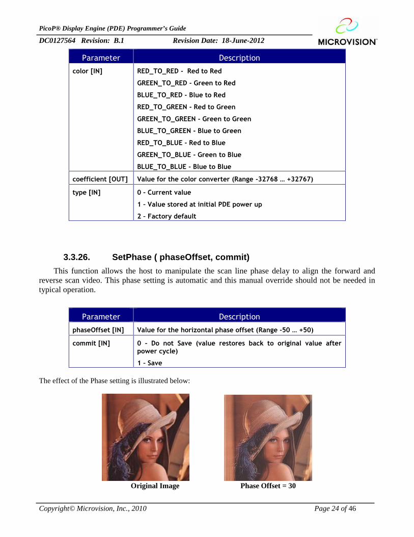
3.3.26. SetPhase ( phaseOffset, commit)This function allows the host to manipulate the scan line phase delay to align the forward and
reverse scan video. This phase setting is automatic and this manual override should not be needed intypical operation.
Parameter Description
phaseOffset [IN] Value for the horizontal phase offset (Range -50 … +50)
commit [IN] 0 – Do not Save (value restores back to original value afterpower cycle)
1 – Save
The effect of the Phase setting is illustrated below:
Original Image Phase Offset = 30
PicoP® Display Engine (PDE) Programmer’s Guide
DC0127564 Revision: B.1 Revision Date: 18-June-2012
Copyright© Microvision, Inc., 2010 Page 25 of 46
3.3.27. GetPhase ( phaseOffset, type)This function retrieves the scan line phase delay.
Parameter Description
phaseOffset [OUT] The current phase offset value
type [IN] 0 – Current value
1 – Value stored at initial PDE power up
2 – Factory default
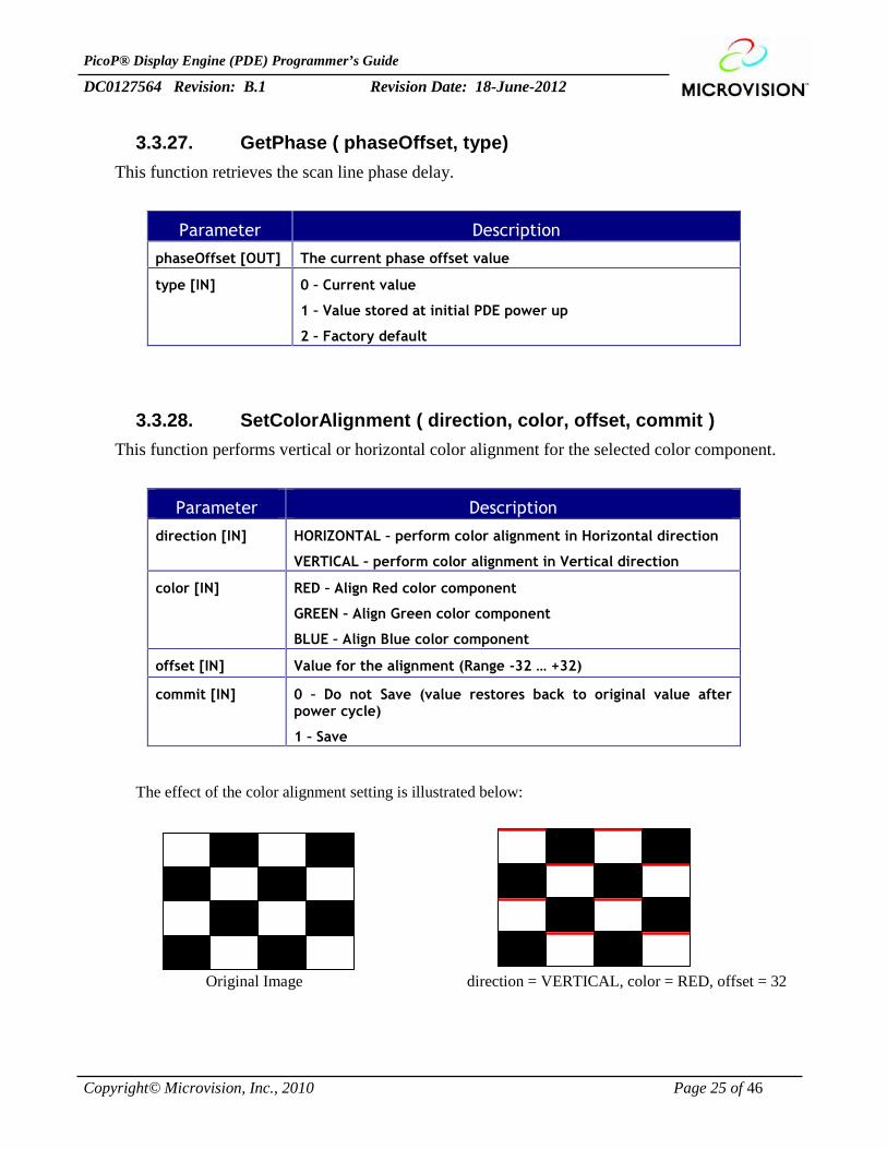
3.3.28. SetColorAlignment ( direction, color, offset, commit )This function performs vertical or horizontal color alignment for the selected color component.
Parameter Description
direction [IN] HORIZONTAL – perform color alignment in Horizontal direction
VERTICAL – perform color alignment in Vertical direction
color [IN] RED – Align Red color component
GREEN – Align Green color component
BLUE – Align Blue color component
offset [IN] Value for the alignment (Range -32 … +32)
commit [IN] 0 – Do not Save (value restores back to original value afterpower cycle)
1 – Save
The effect of the color alignment setting is illustrated below:
Original Image direction = VERTICAL, color = RED, offset = 32
PicoP® Display Engine (PDE) Programmer’s Guide
DC0127564 Revision: B.1 Revision Date: 18-June-2012
Copyright© Microvision, Inc., 2010 Page 26 of 46
3.3.29. GetColorAlignment ( direction, color, offset, type )This function returns the alignment offset in vertical or horizontal direction for a color component.
Parameter Description
direction [IN] HORIZONTAL – color alignment in Horizontal direction
VERTICAL – color alignment in Vertical direction
color [IN] RED – Red color component
GREEN – Green color component
BLUE – Blue color component
offset [OUT] Value for the alignment (Range -32 … +32)
type [IN] 0 – Current value
1 – Value stored at initial PDE power up
2 – Factory default
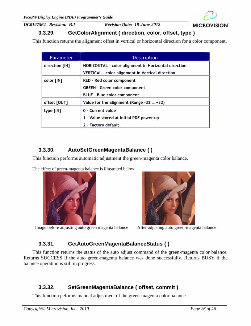
3.3.30. AutoSetGreenMagentaBalance ( )This function performs automatic adjustment the green-magenta color balance.
The effect of green-magenta balance is illustrated below:
Image before adjusting auto green magenta balance After adjusting auto green-magenta balance
3.3.31. GetAutoGreenMagentaBalanceStatus ( )This function returns the status of the auto adjust command of the green-magenta color balance.
Returns SUCCESS if the auto green-magenta balance was done successfully. Returns BUSY if thebalance operation is still in progress.
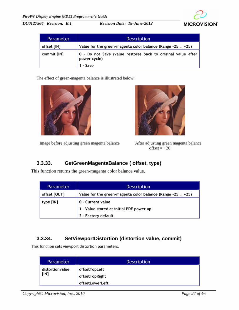
3.3.32. SetGreenMagentaBalance ( offset, commit )This function peforms manual adjustment of the green-magenta color balance.
PicoP® Display Engine (PDE) Programmer’s Guide
DC0127564 Revision: B.1 Revision Date: 18-June-2012
Copyright© Microvision, Inc., 2010 Page 27 of 46
Parameter Description
offset [IN] Value for the green-magenta color balance (Range -25 … +25)
commit [IN] 0 – Do not Save (value restores back to original value afterpower cycle)
1 – Save
The effect of green-magenta balance is illustrated below:
Image before adjusting green magenta balance After adjusting green magenta balanceoffset = +20
3.3.33. GetGreenMagentaBalance ( offset, type)This function returns the green-magenta color balance value.
Parameter Description
offset [OUT] Value for the green-magenta color balance (Range -25 … +25)
type [IN] 0 – Current value
1 – Value stored at initial PDE power up
2 – Factory default
3.3.34. SetViewportDistortion (distortion value, commit)This function sets viewport distortion parameters.
Parameter Description
distortionvalue[IN]
offsetTopLeft
offsetTopRight
offsetLowerLeft
PicoP® Display Engine (PDE) Programmer’s Guide
DC0127564 Revision: B.1 Revision Date: 18-June-2012
Copyright© Microvision, Inc., 2010 Page 28 of 46
offsetLowerRight
commit [IN] 0 – Do not Save (value restores back to original value afterpower cycle)
1 – Save
3.3.35. GetViewportDistortion (distortion value, type)This function gets viewport distortion parameters.
Parameter Description
distortionvalue[OUT]
offsetTopLeft
offsetTopRight
offsetLowerLeft
offsetLowerRight
type [IN] 0 – Current value
1 – Value stored at initial PDE power up
2 – Factory default
3.3.36. SetOutputVideoStateEx (state, commit)This function sets the output video state to be committed to enabled or disabled.
Parameter Description
state [IN] ENABLED – output video state is enabled.
DISABLED – output video state is disabled.
commit [IN] 0 – Do not Save (value restores back to original value afterpower cycle)
1 – Save
3.3.37. GetOutputVideoStateEx (state, type)This function gets the output video state to be committed to enabled or disabled.
Parameter Description
state [OUT] ENABLED – output video state is enabled.
DISABLED – output video state is disabled.
type [IN] 0 – Current value
PicoP® Display Engine (PDE) Programmer’s Guide
DC0127564 Revision: B.1 Revision Date: 18-June-2012
Copyright© Microvision, Inc., 2010 Page 29 of 46
1 – Value stored at initial PDE power up
2 – Factory default
3.3.38. SetSplashScreenTimeout (timeout value, commit)This function sets the timeout for displaying splash screen.
Parameter Description
timeoutVal [IN] Length of SplashScreen Display in milliseconds
commit [IN] 0 – Do not Save (value restores back to original value afterpower cycle)
1 – Save
3.3.39. GetSplashScreenTimeout (timeout value, type)This function gets the timeout for displaying splash screen.
Parameter Description
timeout value[OUT]
Length of SplashScreen Display in milliseconds.
type [IN] 0 – Current value
1 – Value stored at initial PDE power up
2 – Factory default
3.3.40. SetVerticalProjectionAngleOffset (offset value, commit)This function sets the vertical projection angle offset.
Parameter Description
offset Val [IN] Vertical Projection Angle offset
commit [IN] 0 – Do not Save (value restores back to original value after
PicoP® Display Engine (PDE) Programmer’s Guide
DC0127564 Revision: B.1 Revision Date: 18-June-2012
Copyright© Microvision, Inc., 2010 Page 30 of 46
power cycle)
1 – Save
3.3.41. GetVerticalProjectionAngleOffset (offset value, type)This function gets the vertical projection angle offset.
Parameter Description
offset Val [OUT] Vertical Projection Angle offset
type [IN] 0 – Current value
1 – Value stored at initial PDE power up
2 – Factory default
PicoP® Display Engine (PDE) Programmer’s Guide
DC0127564 Revision: B.1 Revision Date: 18-June-2012
Copyright© Microvision, Inc., 2010 Page 31 of 46
3.4. Input Control FunctionsThe Input Control Functions allow the host device to control and configure the PDE video input interface.
3.4.1. SetInputVideoState ( state)This function enables or disables the PDE input video interface. When the input video is disabled, the PDE
frame buffer will not be updated and the output video will contain the last received frame.
Parameter Description
state [IN] ENABLED – Enable the input video
DISABLED – Disable the input video and statically display the lastreceived video frame contained in the frame buffer.
3.4.2. GetInputVideoState ( state)Returns the current state of the input video.
Parameter Description
state [OUT] ENABLED – The input video is enabled
DISABLED – The input video is disabled
3.4.3. SetInputCaptureModeInfo ( modeHandle, captureInfo)This function configures a custom input video mode to be accepted by PDE. This new mode augments the
built-in video modes already supported by the PDE.
Parameter Description
modeHandle [OUT] Returned handle to the added video capture mode
captureInfo [IN] Information on the video capture mode to be supported:
Video clock polarity
VSync Polarity
HSync Polarity
Horizontal Start Position
Horizontal Resolution
Vertical Start Position
Vertical Resolution
Color Space
Interlace Type
PicoP® Display Engine (PDE) Programmer’s Guide
DC0127564 Revision: B.1 Revision Date: 18-June-2012
Copyright© Microvision, Inc., 2010 Page 32 of 46
3.4.4. ModifyInputCaptureModeInfo ( modeHandle, captureInfo)This function modifies the custom input video mode to be accepted by PDE.
Parameter Description
modeHandle [IN] Handle to the added video capture mode
captureInfo [IN] Information on the video capture mode to be supported:
Video clock polarity
VSync Polarity
HSync Polarity
Horizontal Start Position
Horizontal Resolution
Vertical Start Position
Vertical Resolution
Color Space
Interlace Type
3.4.5. CommitCaptureModeInfo ( modeHandle)This function commits the given video capture mode.
Parameter Description
modeHandle [IN] Handle to the added video capture mode
3.4.6. GetCommitedInputCaptureMode ( modeHandle)This function gets the committed custom video capture mode.
Parameter Description
modeHandle [OUT] Handle to the custom video capture mode
3.4.7. GetInputCaptureModeInfo ( modeHandle, captureInfo)Returns the information stored for a specific video capture mode.
Parameter Description
modeHandle [IN] Handle to the video capture mode to be queried
captureInfo [OUT] Video capture mode information:
PicoP® Display Engine (PDE) Programmer’s Guide
DC0127564 Revision: B.1 Revision Date: 18-June-2012
Copyright© Microvision, Inc., 2010 Page 33 of 46
Video clock polarity
VSync Polarity
HSync Polarity
Horizontal Start Position
Horizontal Resolution
Vertical Start Position
Vertical Resolution
Color Space
Interlace Type
3.4.8. SetActiveCaptureMode ( modeHandle)This function sets the input video capture mode to be used. The incoming video MUST match the
parameters defined by the given mode to be displayed correctly.
Parameter Description
modeHandle [IN] Handle to the video capture mode to activate
3.4.9. GetActiveCaptureMode ( modeHandle)Returns the input video capture mode being used.
Parameter Description
modeHandle [OUT] Handle to the video capture mode being used
3.4.10. GetInputVideoProperties ( frameRate, lines )This function returns the detected input video Frame Rate and Lines per Frame. This is a utility
helper function that can be used by the application to help determine the input video format if it is notknown.
Parameter Description
frameRate [OUT] Detected number of video frames per second
lines [OUT] Detected number of video lines per single video frame
PicoP® Display Engine (PDE) Programmer’s Guide
DC0127564 Revision: B.1 Revision Date: 18-June-2012
Copyright© Microvision, Inc., 2010 Page 34 of 46
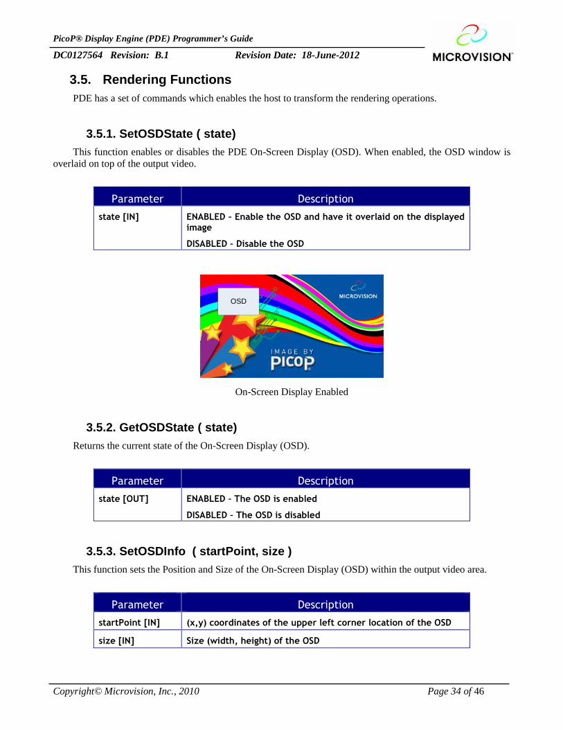
3.5. Rendering FunctionsPDE has a set of commands which enables the host to transform the rendering operations.
3.5.1. SetOSDState ( state)This function enables or disables the PDE On-Screen Display (OSD). When enabled, the OSD window is
overlaid on top of the output video.
Parameter Description
state [IN] ENABLED – Enable the OSD and have it overlaid on the displayedimage
DISABLED – Disable the OSD
OSD
On-Screen Display Enabled
3.5.2. GetOSDState ( state)Returns the current state of the On-Screen Display (OSD).
Parameter Description
state [OUT] ENABLED – The OSD is enabled
DISABLED – The OSD is disabled
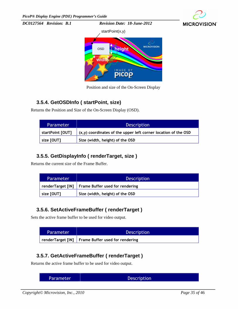
3.5.3. SetOSDInfo ( startPoint, size )This function sets the Position and Size of the On-Screen Display (OSD) within the output video area.
Parameter Description
startPoint [IN] (x,y) coordinates of the upper left corner location of the OSD
size [IN] Size (width, height) of the OSD
PicoP® Display Engine (PDE) Programmer’s Guide
DC0127564 Revision: B.1 Revision Date: 18-June-2012
Copyright© Microvision, Inc., 2010 Page 35 of 46
OSD
startPoint(x,y)
width
height
Position and size of the On-Screen Display
3.5.4. GetOSDInfo ( startPoint, size)Returns the Position and Size of the On-Screen Display (OSD).
Parameter Description
startPoint [OUT] (x,y) coordinates of the upper left corner location of the OSD
size [OUT] Size (width, height) of the OSD
3.5.5. GetDisplayInfo ( renderTarget, size )Returns the current size of the Frame Buffer.
Parameter Description
renderTarget [IN] Frame Buffer used for rendering
size [OUT] Size (width, height) of the OSD
3.5.6. SetActiveFrameBuffer ( renderTarget )Sets the active frame buffer to be used for video output.
Parameter Description
renderTarget [IN] Frame Buffer used for rendering
3.5.7. GetActiveFrameBuffer ( renderTarget )Returns the active frame buffer to be used for video output.
Parameter Description
PicoP® Display Engine (PDE) Programmer’s Guide
DC0127564 Revision: B.1 Revision Date: 18-June-2012
Copyright© Microvision, Inc., 2010 Page 36 of 46
renderTarget [OUT] Frame Buffer currently used for rendering
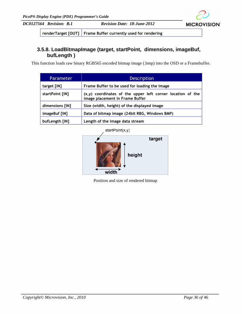
3.5.8. LoadBitmapImage (target, startPoint, dimensions, imageBuf,bufLength )
This function loads raw binary RGB565 encoded bitmap image (.bmp) into the OSD or a Framebuffer.
Parameter Description
target [IN] Frame Buffer to be used for loading the image
startPoint [IN] (x,y) coordinates of the upper left corner location of theimage placement in Frame Buffer
dimensions [IN] Size (width, height) of the displayed image
imageBuf [IN] Data of bitmap image (24bit RBG, Windows BMP)
bufLength [IN] Length of the image data stream
Position and size of rendered bitmap
PicoP® Display Engine (PDE) Programmer’s Guide
DC0127564 Revision: B.1 Revision Date: 18-June-2012
Copyright© Microvision, Inc., 2010 Page 37 of 46
3.5.9. DrawTestPattern ( target, startPoint, dimensions, patternColor,backgroundColor, pattern)
Internal test patterns are stored inside the PDE memory. This function allows the host to display internaltest patterns.
Parameter Description
target [IN] Frame Buffer to be used for loading the image
startPoint [IN] (x,y) coordinates of the upper left corner location of the testpattern
dimensions [IN] Size (width, height) of the displayed test pattern
patternColor [IN] 24-bit RGB Color Value for the test pattern
backgroundColor[IN] 24-bit RGB Color Value for the test pattern background
pattern [IN] 0 – 4 x 4 Checkerboard
1 – 32 Horizontal grayscale ramp
2 – Splash screen
3 – 16 x 12 grid (1 pixel wide)
4- Cross hair (1 pixel wide)
5 – Solid (constant) white
6 – Solid (constant) black
7 – 32 Vertical grayscale ramp
PicoP® Display Engine (PDE) Programmer’s Guide
DC0127564 Revision: B.1 Revision Date: 18-June-2012
Copyright© Microvision, Inc., 2010 Page 38 of 46
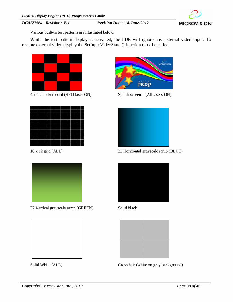
Various built-in test patterns are illustrated below:
While the test pattern display is activated, the PDE will ignore any external video input. Toresume external video display the SetInputVideoState () function must be called.
4 x 4 Checkerboard (RED laser ON) Splash screen (All lasers ON)
16 x 12 grid (ALL) 32 Horizontal grayscale ramp (BLUE)
32 Vertical grayscale ramp (GREEN) Solid black
Solid White (ALL) Cross hair (white on gray background)
PicoP® Display Engine (PDE) Programmer’s Guide
DC0127564 Revision: B.1 Revision Date: 18-June-2012
Copyright© Microvision, Inc., 2010 Page 39 of 46
3.5.10. DrawText ( target, text, length, location, color )This function queues a command to display Text in the OSD or FrameBuffer.
Parameter Description
target [IN] Target to render to (Frame Buffer # or OSD)
text [IN] Text to draw
length [IN] Length of the text (in # of characters)
startPoint [IN] Starting position for the text (lower-left corner)
color [IN] 24-bit RGB Color value for the text
3.5.11. GetTextBoxInfo ( text, length, textBoxRegion )This function returns the dimensions of the bounds of the rectangular region that would be filled with the
given text (but not actually drawn). This will provide the API user with feedback to determine where to drawtext, how to determine line-breaks, how to dimension menu items, etc.
Parameter Description
text [IN] Text to draw
length [IN] Length of the text (in # of characters)
textBoxRegion[OUT]
Region that would be filled with the given text if rendered
3.5.12. DrawPoint ( target, pixel, color)This function queues a command to set a single pixel into the OSD or a FrameBuffer. The queued up draw
commands can be executed with the Render() function.
Parameter Description
target [IN] Target to render to (Frame Buffer # or OSD)
pixel [IN] (x,y) coordinates of the pixel to turn on
color [IN] 24-bit RGB Color Value for the pixel
PicoP® Display Engine (PDE) Programmer’s Guide
DC0127564 Revision: B.1 Revision Date: 18-June-2012
Copyright© Microvision, Inc., 2010 Page 40 of 46
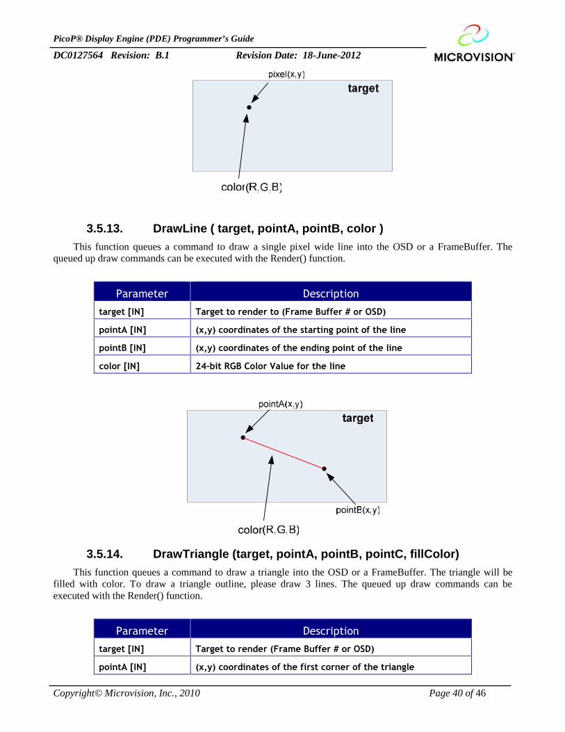
3.5.13. DrawLine ( target, pointA, pointB, color )This function queues a command to draw a single pixel wide line into the OSD or a FrameBuffer. The
queued up draw commands can be executed with the Render() function.
Parameter Description
target [IN] Target to render to (Frame Buffer # or OSD)
pointA [IN] (x,y) coordinates of the starting point of the line
pointB [IN] (x,y) coordinates of the ending point of the line
color [IN] 24-bit RGB Color Value for the line
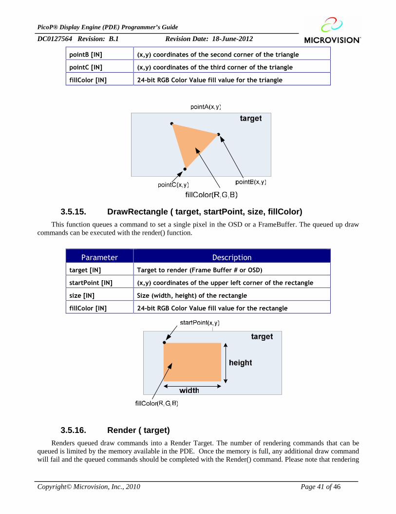
3.5.14. DrawTriangle (target, pointA, pointB, pointC, fillColor)This function queues a command to draw a triangle into the OSD or a FrameBuffer. The triangle will be
filled with color. To draw a triangle outline, please draw 3 lines. The queued up draw commands can beexecuted with the Render() function.
Parameter Description
target [IN] Target to render (Frame Buffer # or OSD)
pointA [IN] (x,y) coordinates of the first corner of the triangle
PicoP® Display Engine (PDE) Programmer’s Guide
DC0127564 Revision: B.1 Revision Date: 18-June-2012
Copyright© Microvision, Inc., 2010 Page 41 of 46
pointB [IN] (x,y) coordinates of the second corner of the triangle
pointC [IN] (x,y) coordinates of the third corner of the triangle
fillColor [IN] 24-bit RGB Color Value fill value for the triangle
3.5.15. DrawRectangle ( target, startPoint, size, fillColor)This function queues a command to set a single pixel in the OSD or a FrameBuffer. The queued up draw
commands can be executed with the render() function.
Parameter Description
target [IN] Target to render (Frame Buffer # or OSD)
startPoint [IN] (x,y) coordinates of the upper left corner of the rectangle
size [IN] Size (width, height) of the rectangle
fillColor [IN] 24-bit RGB Color Value fill value for the rectangle
3.5.16. Render ( target)Renders queued draw commands into a Render Target. The number of rendering commands that can be
queued is limited by the memory available in the PDE. Once the memory is full, any additional draw commandwill fail and the queued commands should be completed with the Render() command. Please note that rendering
PicoP® Display Engine (PDE) Programmer’s Guide
DC0127564 Revision: B.1 Revision Date: 18-June-2012
Copyright© Microvision, Inc., 2010 Page 42 of 46
into a Frame Buffer that is actively capturing input video will result in the rendered pixels to be overwritten byinput video.
Parameter Description
target [IN] Target to render (Frame Buffer # or OSD)
PicoP® Display Engine (PDE) Programmer’s Guide
DC0127564 Revision: B.1 Revision Date: 18-June-2012
Copyright© Microvision, Inc., 2010 Page 43 of 46
3.6. System Management FunctionsThe System management functions enable the host application to query system status as health.
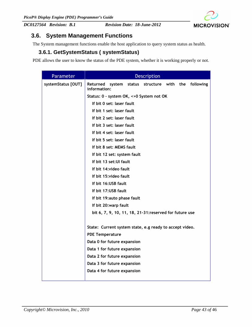
3.6.1. GetSystemStatus ( systemStatus)PDE allows the user to know the status of the PDE system, whether it is working properly or not.
Parameter Description
systemStatus [OUT] Returned system status structure with the followinginformation:
Status: 0 – system OK, <>0 System not OK
If bit 0 set: laser fault
If bit 1 set: laser fault
If bit 2 set: laser fault
If bit 3 set: laser fault
If bit 4 set: laser fault
If bit 5 set: laser fault
If bit 8 set: MEMS fault
If bit 12 set: system fault
If bit 13 set:UI fault
If bit 14:video fault
If bit 15:video fault
If bit 16:USB fault
If bit 17:USB fault
If bit 19:auto phase fault
If bit 20:warp fault
bit 6, 7, 9, 10, 11, 18, 21-31:reserved for future use
State: Current system state, e.g ready to accept video.
PDE Temperature
Data 0 for future expansion
Data 1 for future expansion
Data 2 for future expansion
Data 3 for future expansion
Data 4 for future expansion
PicoP® Display Engine (PDE) Programmer’s Guide
DC0127564 Revision: B.1 Revision Date: 18-June-2012
Copyright© Microvision, Inc., 2010 Page 44 of 46
3.6.2. GetSystemInfo ( systemInfo)This function allows the host to retrieve information about the PDE system which includes System Serial
Number, Software Version Number and ASIC Version Numbers. This information can be used fortroubleshooting and configuration management.
Parameter Description
systemInfo [OUT] Returned system information structure with the followinginformation:
PDE System Serial Number
PDE Software Version
PDE Electronics Version
PDE Runtime
Data 0 for future expansion
Data 1 for future expansion
Data 2 for future expansion
Data 3 for future expansion
3.6.3. GetEventLog ( numEvents, events)PDE maintains a log of system events that have occurred. The host can retrieve the event log information of
last events with the GetEventLog() function. This function is typically used for system troubleshooting.
Parameter Description
numEvents[IN]
Number of events to be retrieved
Events [OUT] Returned events, list of event data structures
3.6.4. SetSystemPowerState ( state)This function sets the PDE system power state.
Parameter Description
state [IN] Set the system to one of the following power states:
RUNNING - System Running
STANDBY - System Standby
SHUTDOWN - System Shutdown
PicoP® Display Engine (PDE) Programmer’s Guide
DC0127564 Revision: B.1 Revision Date: 18-June-2012
Copyright© Microvision, Inc., 2010 Page 45 of 46
3.6.5. GetSystemPowerState ( state)This function returns the current PDE system power state.
Parameter Description
state [OUT] The current PDE power state:
RUNNING - System Running
STANDBY - System Standby
SHUTDOWN - System Shutdown
3.6.6. RestoreFactoryConfig (commit)This function restores the PDE system configuration to the factory configuration.
Parameter Description
commit [IN] 0 – Do not Save (value restores back to original value after powercycle)
1 – Save
3.6.7. SaveSplashScreen ( target)This function takes a snapshot of the specified frame buffer and saves the content as the Splash Screen.
Parameter Description
target [IN] The frame buffer to take snapshot of.
3.6.8. UpgradeSoftware (image, size)The PDE supports upgrading the embedded software of the system with the UpgradeSoftware() function.
Parameter Description
image [IN] Data of the SW binary
size [IN] Size of the SW binary
3.6.9. UpgradeSoftware_Ex (image, size, callback)This function upgrades the embedded software of the system. The host can retrieve the index of the packets
being sent. This function is typically used for getting the upgrade progress information. If the callback is givenas NULL this function does the same functionality as UpgradeSoftware.

PicoP® Display Engine (PDE) Programmer’s Guide
DC0127564 Revision: B.1 Revision Date: 18-June-2012
Copyright© Microvision, Inc., 2010 Page 46 of 46
Parameter Description
image [IN] Data of the SW binary
size [IN] Size of the SW binary
callback[IN] Callback function to pass current index of the packet, maximumindex of the packets to be sent and destination device id

![582 JOURNAL OF DISPLAY TECHNOLOGY, VOL. 8, NO. 10, … · vision’s PicoP™ handheld pico projector is a good example of this type of scanned laser projector [16]. Unlike [7] and](https://img.pdfslide.us/doc/110x75/5f53358586451b1ba80ff0dc/582-journal-of-display-technology-vol-8-no-10-visionas-picopa-handheld.jpg)