Embed Size (px)
Citation preview

3.1 Connect the parts
3.2 WiFi antenna
3.3 Camera module (optional)
PICO-PI-IMX8MQuickstart Guide
3 Installation InstructionsThis installation guide will help you to assemble your development kit using step-by-step instructions to make sure all parts (development board, WiFi antenna, camera module and display) are working.
Please follow the steps below to properly install the WiFi antenna.Step 1: Prepare WiFi antenna, extender cable and development board. Step 2: Locate the round antenna pin on the development board. Make sure the connector is aligned with the pin. Press the small round connector at the end of the extender cable onto this pin. You will need to press down until you hear a click sound.Step 3: Screw the extender cable into the base of the WiFi antenna.
Connect the parts in the following order. Please note that some versions of the PICO-PI-IMX8M evaluation kit do not include the camera, multi-touch display, and/or cardboard stand.Tips: Do not power your board during the installation process.
Please follow the steps below to properly install the camera module.Step 1: Prepare camera module, FPC cable and evaluation board. Turn the camera module over to reveal a white connector near the edge of the module.Step 2: Swivel the black retaining clip upward. Step 3: Insert either end of the camera module cable into the white connector. Make sure that the blue side of the ribbon is facing up and is aligned straight with the connector. The silver pins on the FPC cable should be facing down. Step 4: Swivel the retaining clip back down to hold the FPC cable in place.Steps 5 and 6: Repeat these same steps with the other end of the cable and the connector on the board.Tips: After installation remove the protective blue film from the camera lens.
INNOVATORS OF TECHNOLOGY
2 Dimensions
1 Safety PrecautionsThank you for purchasing a TechNexion PICO series evaluation kit based on NXP i.MX8M applications processor. This installation guide will be helpful in the installation, wiring and inspection of your TechNexion evaluation kit. Before using the product, please read this guide to ensure correct use. You should thoroughly understand all safety precautions before proceeding with the installation, wiring, and operation. Place this instruction sheet in a safe location for future reference.
• Keep the device dry. Precipitation, humidity, and all types of liquids or moisture can contain minerals that will corrode electronic circuits. If your device does get wet, allow it to dry completely.• Do not use or store the device in dusty or dirty areas. Its parts and electronic components can be damaged.• Do not store the device in hot areas. High temperatures can shorten the life of electronic devices, damage batteries, and warp or melt certain plastics.• Do not store the device in cold areas. When the device returns to its normal temperature, moisture can form inside the device and damage electronic circuit boards.• This product is designed for specific applications and needs to be installed by qualified personnel.• Do not drop, knock, or shake the device. Rough handling can break internal circuit boards and fine mechanics.• Do not paint the device. Paint can clog the parts and prevent proper operation.• Unauthorized modifications or attachments could damage the device and may violate regulations governing radio devices.
• Do not touch any internal or exposed parts of the device as electrical shock may result.• Do not open the device while power is on. Otherwise electrical shock may result.• Do not use harsh chemicals, cleaning solvents, or strong detergents to clean the device.• Be sure the ventilation holes are not obstructed during operation. Otherwise malfunction may result due to bad ventilation or overheating.
These suggestions apply equally to your device, battery, charger, or any enhancement. If any device is not working properly, take it to the nearest authorized service facility for service.
• Make sure that the available power source matches the required input power of the device. Failure to observe this caution may result in electric shock or fire.
1.1 Storage and Installation
1.2 Wiring
1.3 Maintenance and Inspection
!
Unit : mm
85
56
2.75
36.0
752.4
3.5
28.7
52.5
51.82
32.5
2.75
2
25.219.4
h<2mm
61.51.67.8
1 2 3
1 2 3
4 5 6
1 2
STEP1 STEP2 STEP3
STEP1 STEP2 STEP3
STEP4 STEP5 STEP6
3.4 Display (optional)
3.5 Cardboard stand (optional)
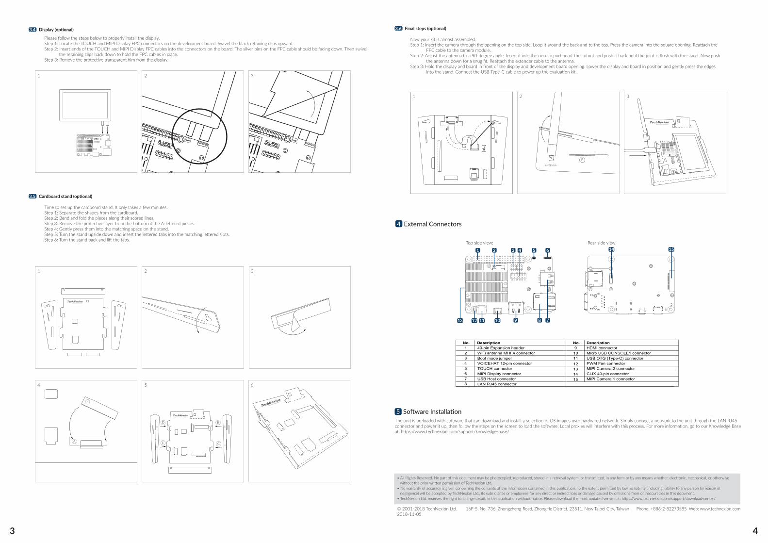
4 External Connectors
Please follow the steps below to properly install the display.Step 1: Locate the TOUCH and MIPI Display FPC connectors on the development board. Swivel the black retaining clips upward. Step 2: Insert ends of the TOUCH and MIPI Display FPC cables into the connectors on the board. The silver pins on the FPC cable should be facing down. Then swivel the retaining clips back down to hold the FPC cables in place. Step 3: Remove the protective transparent film from the display.
Time to set up the cardboard stand. It only takes a few minutes.Step 1: Separate the shapes from the cardboard. Step 2: Bend and fold the pieces along their scored lines.Step 3: Remove the protective layer from the bottom of the A-lettered pieces.Step 4: Gently press them into the matching space on the stand. Step 5: Turn the stand upside down and insert the lettered tabs into the matching lettered slots.Step 6: Turn the stand back and lift the tabs.
3.6 Final steps (optional)
Now your kit is almost assembled. Step 1: Insert the camera through the opening on the top side. Loop it around the back and to the top. Press the camera into the square opening. Reattach the FPC cable to the camera module. Step 2: Adjust the antenna to a 90-degree angle. Insert it into the circular portion of the cutout and push it back until the joint is flush with the stand. Now push the antenna down for a snug fit. Reattach the extender cable to the antenna. Step 3: Hold the display and board in front of the display and development board opening. Lower the display and board in position and gently press the edges into the stand. Connect the USB Type-C cable to power up the evaluation kit.
Top side view: Rear side view:
• All Rights Reserved. No part of this document may be photocopied, reproduced, stored in a retrieval system, or transmitted, in any form or by any means whether, electronic, mechanical, or otherwise without the prior written permission of TechNexion Ltd.• No warranty of accuracy is given concerning the contents of the information contained in this publication. To the extent permitted by law no liability (including liability to any person by reason of negligence) will be accepted by TechNexion Ltd., its subsidiaries or employees for any direct or indirect loss or damage caused by omissions from or inaccuracies in this document.• TechNexion Ltd. reserves the right to change details in this publication without notice. Please download the most updated version at: https://www.technexion.com/support/download-center/
Phone: +886-2-82273585 Web: www.technexion.com16F-5, No. 736, Zhongzheng Road, ZhongHe District, 23511, New Taipei City, Taiwan© 2001-2018 TechNexion Ltd.2018-11-05
5 Software InstallationThe unit is preloaded with software that can download and install a selection of OS images over hardwired network. Simply connect a network to the unit through the LAN RJ45 connector and power it up, then follow the steps on the screen to load the software. Local proxies will interfere with this process. For more information, go to our Knowledge Base at: https://www.technexion.com/support/knowledge-base/
Description No. No. Description123456
121314157
8
91011
40-pin Expansion headerWiFi antenna MHF4 connector Boot mode jumperVOICEHAT 12-pin connectorTOUCH connectorMIPI Display connectorUSB Host connectorLAN RJ45 connector
HDMI connectorMicro USB CONSOLE1 connectorUSB OTG (Type-C) connectorPWM Fan connectorMIPI Camera 2 connectorCLIX 40-pin connectorMIPI Camera 1 connector
10
1 2 5 6
7891112
14 15
13
3 4
1 2 3
1 2 3
4 5 6
1 2 3
A
D BB
B
CC
CE
D
E E
D
A
FANTENNA
3 4