Embed Size (px)
Citation preview
© 2006 Microchip Technology Inc. DS51275C
PICDEM™ 2 PlusDemonstration Board
User’s Guide
Note the following details of the code protection feature on Microchip devices:
• Microchip products meet the specification contained in their particular Microchip Data Sheet.
• Microchip believes that its family of products is one of the most secure families of its kind on the market today, when used in the intended manner and under normal conditions.
• There are dishonest and possibly illegal methods used to breach the code protection feature. All of these methods, to our knowledge, require using the Microchip products in a manner outside the operating specifications contained in Microchip’s Data Sheets. Most likely, the person doing so is engaged in theft of intellectual property.
• Microchip is willing to work with the customer who is concerned about the integrity of their code.
• Neither Microchip nor any other semiconductor manufacturer can guarantee the security of their code. Code protection does not mean that we are guaranteeing the product as “unbreakable.”
Code protection is constantly evolving. We at Microchip are committed to continuously improving the code protection features of ourproducts. Attempts to break Microchip’s code protection feature may be a violation of the Digital Millennium Copyright Act. If such actsallow unauthorized access to your software or other copyrighted work, you may have a right to sue for relief under that Act.
Information contained in this publication regarding deviceapplications and the like is provided only for your convenienceand may be superseded by updates. It is your responsibility toensure that your application meets with your specifications.MICROCHIP MAKES NO REPRESENTATIONS ORWARRANTIES OF ANY KIND WHETHER EXPRESS ORIMPLIED, WRITTEN OR ORAL, STATUTORY OROTHERWISE, RELATED TO THE INFORMATION,INCLUDING BUT NOT LIMITED TO ITS CONDITION,QUALITY, PERFORMANCE, MERCHANTABILITY ORFITNESS FOR PURPOSE. Microchip disclaims all liabilityarising from this information and its use. Use of Microchipdevices in life support and/or safety applications is entirely atthe buyer’s risk, and the buyer agrees to defend, indemnify andhold harmless Microchip from any and all damages, claims,suits, or expenses resulting from such use. No licenses areconveyed, implicitly or otherwise, under any Microchipintellectual property rights.
DS51275C-page ii
Trademarks
The Microchip name and logo, the Microchip logo, Accuron, dsPIC, KEELOQ, microID, MPLAB, PIC, PICmicro, PICSTART, PRO MATE, PowerSmart, rfPIC and SmartShunt are registered trademarks of Microchip Technology Incorporated in the U.S.A. and other countries.
AmpLab, FilterLab, Migratable Memory, MXDEV, MXLAB, SEEVAL, SmartSensor and The Embedded Control Solutions Company are registered trademarks of Microchip Technology Incorporated in the U.S.A.
Analog-for-the-Digital Age, Application Maestro, CodeGuard, dsPICDEM, dsPICDEM.net, dsPICworks, ECAN, ECONOMONITOR, FanSense, FlexROM, fuzzyLAB, In-Circuit Serial Programming, ICSP, ICEPIC, Linear Active Thermistor, Mindi, MiWi, MPASM, MPLIB, MPLINK, PICkit, PICDEM, PICDEM.net, PICLAB, PICtail, PowerCal, PowerInfo, PowerMate, PowerTool, REAL ICE, rfLAB, rfPICDEM, Select Mode, Smart Serial, SmartTel, Total Endurance, UNI/O, WiperLock and ZENA are trademarks of Microchip Technology Incorporated in the U.S.A. and other countries.
SQTP is a service mark of Microchip Technology Incorporated in the U.S.A.
All other trademarks mentioned herein are property of their respective companies.
© 2006, Microchip Technology Incorporated, Printed in the U.S.A., All Rights Reserved.
Printed on recycled paper.
© 2006 Microchip Technology Inc.
Microchip received ISO/TS-16949:2002 certification for its worldwide headquarters, design and wafer fabrication facilities in Chandler and Tempe, Arizona, Gresham, Oregon and Mountain View, California. The Company’s quality system processes and procedures are for its PIC®
8-bit MCUs, KEELOQ® code hopping devices, Serial EEPROMs, microperipherals, nonvolatile memory and analog products. In addition, Microchip’s quality system for the design and manufacture of development systems is ISO 9001:2000 certified.
PICDEM 2 PLUS USER’S GUIDE
Table of Contents
Preface ........................................................................................................................... 1
Chapter 1. Introduction1.1 Welcome ........................................................................................................ 51.2 PICDEM 2 Plus Demonstration Board ........................................................... 61.3 Sample Devices ............................................................................................. 71.4 Sample Programs ........................................................................................... 71.5 PICDEM 2 Plus Demonstration Board User’s Guide ...................................... 81.6 Reference Documents .................................................................................... 8
Chapter 2. Getting Started2.1 PICDEM 2 Plus Demonstration Board as a Stand-Alone Board –
Preprogrammed Device ............................................................................ 92.2 PICDEM 2 Plus Demonstration Board Used with an In-Circuit Emulator or
In-Circuit Debugger ................................................................................ 10
Chapter 3. Tutorial3.1 Tutorial Program Operation .......................................................................... 113.2 Source Code and Application Notes ............................................................ 13
Appendix A. Hardware DetailA.1 Processor Sockets ....................................................................................... 15A.2 Display ......................................................................................................... 15A.3 Power Supply ............................................................................................... 15A.4 RS-232 Serial Port ....................................................................................... 15A.5 Switches ....................................................................................................... 16A.6 Oscillator Options ......................................................................................... 16A.7 Analog Input ................................................................................................. 16A.8 ICD Connector ............................................................................................. 16A.9 Temperature Sensor .................................................................................... 16A.10 Serial EEPROM ......................................................................................... 16A.11 LCD ............................................................................................................ 16A.12 Sample Devices ......................................................................................... 17A.13 Board Layout and Schematics ................................................................... 18
Index ............................................................................................................................. 21
Worldwide Sales and Service .................................................................................... 22
© 2006 Microchip Technology Inc. DS51275C-page iii
PICDEM 2 Plus User’s Guide
DS51275C-page iv © 2006 Microchip Technology Inc.
PICDEM™ 2 PLUSDEMONSTATION BOARD
USER’S GUIDE
Preface
INTRODUCTION
This chapter contains general information that will be useful to know before using the PICDEM™ 2 Plus Demonstation Board User’s Guide. Items discussed in this chapter include:
• About this Guide• Conventions Used in this Guide• Recommended Reading• The Microchip Web Site• Development Systems Customer Change Notification Service• Customer Support
ABOUT THIS GUIDE
Document Layout
This document describes how to use the PICDEM 2 Plus Demonstration Board as a development tool to emulate and debug firmware on a target board. The manual layout is as follows:
• Chapter 1. Introduction – Describes the hardware of the PICDEM 2 Plus Demonstration Board.
• Chapter 2. Getting Started – Describes how to use the PICDEM 2 Plus Demonstration Board.
• Chapter 3. Tutorial – Describes how to use the application in demo mode and also how it can be customized.
• Appendix A. Hardware Detail – Shows the schematic and layout diagrams for the PICDEM 2 Plus Demonstration Board.
NOTICE TO CUSTOMERS
All documentation becomes dated, and this manual is no exception. Microchip tools and documentation are constantly evolving to meet customer needs, so some actual dialogs and/or tool descriptions may differ from those in this document. Please refer to our web site (www.microchip.com) to obtain the latest documentation available.
Documents are identified with a “DS” number. This number is located on the bottom of each page, in front of the page number. The numbering convention for the DS number is “DSXXXXXA”, where “XXXXX” is the document number and “A” is the revision level of the document.
For the most up-to-date information on development tools, see the MPLAB® IDE on-line help. Select the Help menu, and then Topics to open a list of available on-line help files.
© 2006 Microchip Technology Inc. DS51275C-page 1
PICDEM™ 2 Plus Demonstation Board User’s Guide
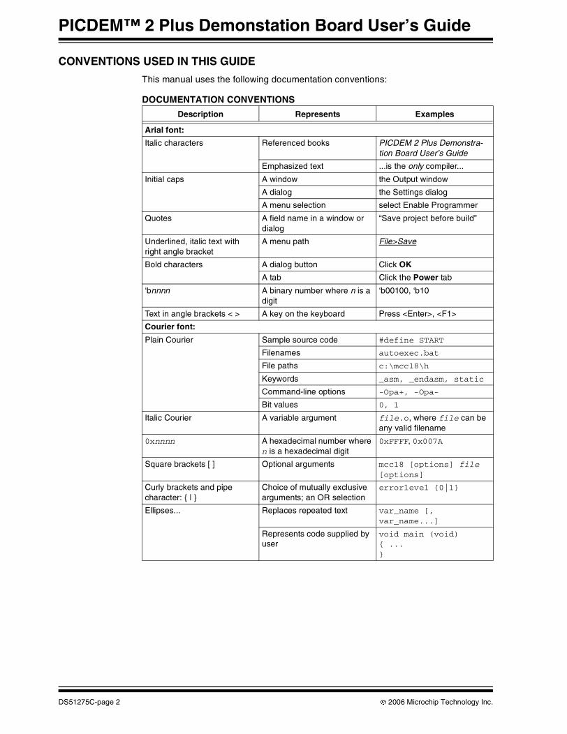
CONVENTIONS USED IN THIS GUIDE
This manual uses the following documentation conventions:
DOCUMENTATION CONVENTIONS
Description Represents Examples
Arial font:
Italic characters Referenced books PICDEM 2 Plus Demonstra-tion Board User’s Guide
Emphasized text ...is the only compiler...
Initial caps A window the Output window
A dialog the Settings dialog
A menu selection select Enable Programmer
Quotes A field name in a window or dialog
“Save project before build”
Underlined, italic text with right angle bracket
A menu path File>Save
Bold characters A dialog button Click OK
A tab Click the Power tab
‘bnnnn A binary number where n is a digit
‘b00100, ‘b10
Text in angle brackets < > A key on the keyboard Press <Enter>, <F1>
Courier font:
Plain Courier Sample source code #define START
Filenames autoexec.bat
File paths c:\mcc18\h
Keywords _asm, _endasm, static
Command-line options -Opa+, -Opa-
Bit values 0, 1
Italic Courier A variable argument file.o, where file can be any valid filename
0xnnnn A hexadecimal number where n is a hexadecimal digit
0xFFFF, 0x007A
Square brackets [ ] Optional arguments mcc18 [options] file [options]
Curly brackets and pipe character: { | }
Choice of mutually exclusive arguments; an OR selection
errorlevel {0|1}
Ellipses... Replaces repeated text var_name [, var_name...]
Represents code supplied by user
void main (void){ ...}
DS51275C-page 2 © 2006 Microchip Technology Inc.
RECOMMENDED READING
This user’s guide describes how to use the PICDEM 2 Plus Demonstration Board Kit. Other useful documents are listed below.
Readme Files
For the latest information on using other tools, read the tool-specific Readme files in the Readmes subdirectory of the MPLAB IDE installation directory. The Readme files contain update information and known issues that may not be included in this user’s guide.
THE MICROCHIP WEB SITE
Microchip provides online support via our web site at www.microchip.com. This web site is used as a means to make files and information easily available to customers. Accessible by using your favorite Internet browser, the web site contains the following information:
• Product Support – Data sheets and errata, application notes and sample programs, design resources, user’s guides and hardware support documents, latest software releases and archived software
• General Technical Support – Frequently Asked Questions (FAQs), technical support requests, online discussion groups, Microchip consultant program member listing
• Business of Microchip – Product selector and ordering guides, latest Microchip press releases, listing of seminars and events, listings of Microchip sales offices, distributors and factory representatives
© 2006 Microchip Technology Inc. DS51275C-page 3
PICDEM™ 2 Plus Demonstation Board User’s Guide
DEVELOPMENT SYSTEMS CUSTOMER CHANGE NOTIFICATION SERVICE
Microchip’s customer notification service helps keep customers current on Microchip products. Subscribers will receive e-mail notification whenever there are changes, updates, revisions or errata related to a specified product family or development tool of interest.
To register, access the Microchip web site at www.microchip.com, click on Customer Change Notification and follow the registration instructions.
The Development Systems product group categories are:
• Compilers – The latest information on Microchip C compilers and other language tools. These include the MPLAB C18 and MPLAB C30 C compilers; MPASM™ and MPLAB ASM30 assemblers; MPLINK™ and MPLAB LINK30 object linkers; and MPLIB™ and MPLAB LIB30 object librarians.
• Emulators – The latest information on Microchip in-circuit emulators.This includes the MPLAB ICE 2000 and MPLAB ICE 4000.
• In-Circuit Debuggers – The latest information on the Microchip in-circuit debugger, MPLAB ICD 2.
• MPLAB® IDE – The latest information on Microchip MPLAB IDE, the Windows® Integrated Development Environment for development systems tools. This list is focused on the MPLAB IDE, MPLAB SIM simulator, MPLAB IDE Project Manager and general editing and debugging features.
• Programmers – The latest information on Microchip programmers. These include the MPLAB PM3 and PRO MATE® II device programmers and the PICSTART® Plus and PICkit™ 1 development programmers.
CUSTOMER SUPPORT
Users of Microchip products can receive assistance through several channels:
• Distributor or Representative• Local Sales Office• Field Application Engineer (FAE)• Technical Support
Customers should contact their distributor, representative or field application engineer (FAE) for support. Local sales offices are also available to help customers. A listing of sales offices and locations is included in the back of this document.
Technical support is available through the web site at: http://support.microchip.com
DS51275C-page 4 © 2006 Microchip Technology Inc.
PICDEM™ 2 PLUSDEMONSTRATION
BOARD USER’S GUIDE
Chapter 1. Introduction
1.1 WELCOME
Thank you for purchasing the PICDEM 2 Plus Demonstration Board from Microchip Technology Incorporated. The PICDEM 2 Plus Demonstration Board is a simple board which demonstrates the capabilities of the 18, 28 and 40-pin PIC16 and PIC18 devices.
The PICDEM 2 Plus Demonstration Board can be used stand-alone with a programmed part, with an in-circuit emulator (e.g., MPLAB® ICE) or with an in-circuit debugger (e.g., MPLAB ICD 2). Sample programs are provided to demonstrate the unique features of the supported devices.
The PICDEM 2 Plus Demonstration Board Kit comes with the following:
1. PICDEM 2 Plus Demonstration Board (Figure 1-1)2. Sample devices3. CD-ROM, which contains:
a) Sample programsb) PICDEM 2 Plus Demonstration Board User’s Guidec) Reference Documents
If you are missing any part of the kit, please contact your nearest Microchip sales office listed in the back of this publication for help.
© 2006 Microchip Technology Inc. DS51275C-page 5
PICDEM™ 2 Plus Demonstration Board User’s Guide
1.2 PICDEM 2 PLUS DEMONSTRATION BOARD
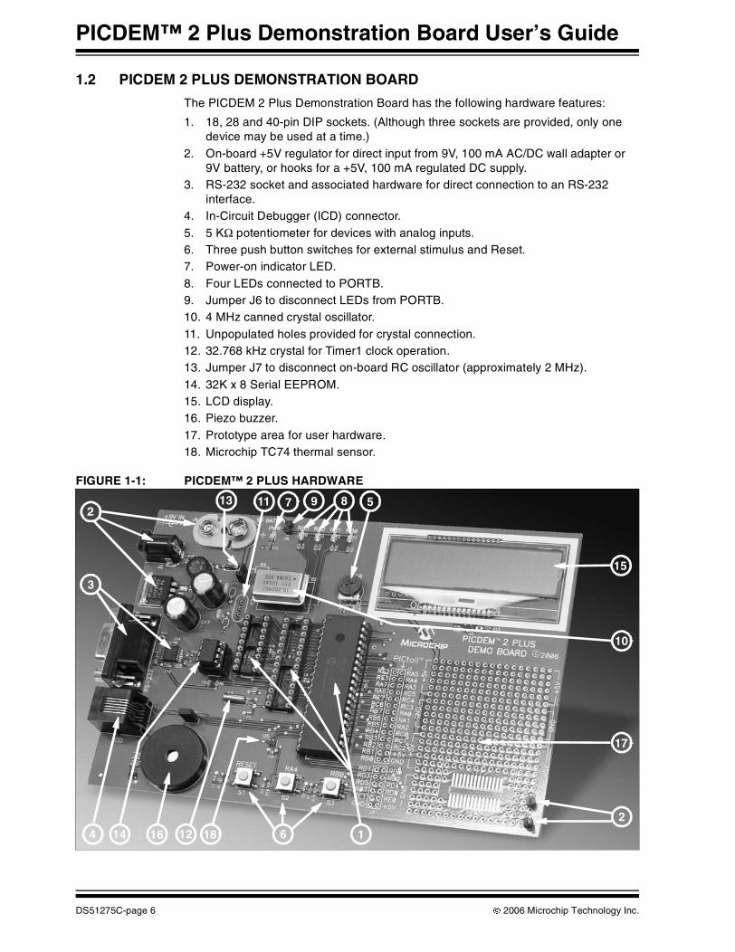
The PICDEM 2 Plus Demonstration Board has the following hardware features:
1. 18, 28 and 40-pin DIP sockets. (Although three sockets are provided, only one device may be used at a time.)
2. On-board +5V regulator for direct input from 9V, 100 mA AC/DC wall adapter or 9V battery, or hooks for a +5V, 100 mA regulated DC supply.
3. RS-232 socket and associated hardware for direct connection to an RS-232 interface.
4. In-Circuit Debugger (ICD) connector.5. 5 KΩ potentiometer for devices with analog inputs.6. Three push button switches for external stimulus and Reset.7. Power-on indicator LED.8. Four LEDs connected to PORTB.9. Jumper J6 to disconnect LEDs from PORTB.10. 4 MHz canned crystal oscillator.11. Unpopulated holes provided for crystal connection.12. 32.768 kHz crystal for Timer1 clock operation.13. Jumper J7 to disconnect on-board RC oscillator (approximately 2 MHz).14. 32K x 8 Serial EEPROM.15. LCD display.16. Piezo buzzer.17. Prototype area for user hardware.18. Microchip TC74 thermal sensor.
FIGURE 1-1: PICDEM™ 2 PLUS HARDWARE
1
5
6
2
3
17
87
16
913
4
10
11
14 18
212
15
DS51275C-page 6 © 2006 Microchip Technology Inc.
Introduction
1.3 SAMPLE DEVICES
Two Flash devices are included. The device types may change, but will generally include PIC16 and PIC18 40-pin DIP devices.
1.4 SAMPLE PROGRAMS
The PICDEM 2 Plus Demonstration Board Kit includes a CD-ROM with sample demonstration programs. These programs may be used with the included sample devices, with an In-Circuit Emulator (ICE) or with an In-Circuit Debugger (ICD). For each type of device (PIC16 or PIC18), demo source code (several ASM files) and compiled code (one hex file) are provided.
© 2006 Microchip Technology Inc. DS51275C-page 7
PICDEM™ 2 Plus Demonstration Board User’s Guide
1.5 PICDEM 2 PLUS DEMONSTRATION BOARD USER’S GUIDE
This document describes the PICDEM 2 Plus Demonstration Board, tutorial and demonstration software. Detailed information on individual microcontrollers may be found in the device’s respective data sheet. Detailed information on In-Circuit Emulator (ICE) or In-Circuit Debugger (ICD) systems may be found in the respective tool’s user guide.
Chapter 1: Introduction – This chapter introduces the PICDEM 2 Plus Demonstration Board and provides a brief description of the hardware.
Chapter 2: Getting Started – This chapter goes through a basic step-by-step process for getting your PICDEM 2 Plus Demonstration Board up and running as a stand-alone board or with an ICE or ICD.
Chapter 3: Tutorial – This chapter provides a detailed description of the tutorial program.
Appendix A: Hardware Description: This appendix describes in detail the hardware of the PICDEM 2 Plus Demonstration Board.
1.6 REFERENCE DOCUMENTS
Reference Documents may be obtained by contacting your nearest Microchip sales office (listed in the back of this document) or by downloading via the Microchip web site (www.microchip.com).
• Individual Data Sheets and Reference Manuals:- “PIC16F87XA Data Sheet” (DS39582)- “PIC18F2420/2520/4420/4520 Data Sheet” (DS39631)- “PIC® Mid-Range MCU Family Reference Manual” (DS33023)- “PIC® 18C MCU Family Reference Manual” (DS39500)- “TC74 Tiny Serial Digital Thermal Sensor Technical Brief” (DS21462)
• “MPLAB® IDE, Simulator, Editor User’s Guide” (DS51025)• “MPASM™ Assembler, MPLINK™ Object Linker and MPLIB™ Object Librarian
User’s Guide” (DS33014)• “PRO MATE® II User’s Guide” (DS30082)• “MPLAB® IDE PICSTART® Plus User’s Guide” (DS51028)• “MPLAB® ICE Emulator User’s Guide” (DS51159)• “MPLAB® ICD 2 User’s Guide” (DS51331)
DS51275C-page 8 © 2006 Microchip Technology Inc.

PICDEM™ 2 PLUSDEMONSTRATION
BOARD USER’S GUIDE
Chapter 2. Getting Started
The PICDEM 2 Plus Demonstration Board may be used as a stand-alone board with a preprogrammed device, with an In-Circuit Emulator (ICE) or with an In-Circuit Debug-ger (ICD). For a list of PIC® microcontroller compatible ICEs or ICDs, please refer to the Development Systems Ordering Guide (DS30177) or the third party section of the Microchip web site: www.microchip.com/thirdparty.
2.1 PICDEM 2 PLUS DEMONSTRATION BOARD AS A STAND-ALONE BOARD – PREPROGRAMMED DEVICE
The PICDEM 2 Plus Demonstration Board may be demonstrated immediately by following the steps listed below:
• Place the preprogrammed sample device in the appropriate socket on the PICDEM 2 Plus Demonstration Board board.
• Place a jumper on J6 (to enable the LEDs).• Verify that the board is set up for a 4 MHz canned oscillator (i.e., no jumper on J7;
a 4 MHz oscillator in Y2; Y1, C4 and C5 are unpopulated).• Apply power to the PICDEM 2 Plus Demonstration Board. For information on
acceptable power sources, see Appendix A.
To reprogram the sample device, the following will be necessary:
1. Program source code.
User source code may be used to program the device or, if this has previously been done, the sample program may be restored from the file on the included CD-ROM.
2. An assembler, such as MPASM™ assembler (available with MPLAB IDE), or a compiler, such as MPLAB C18 (PIC18 devices only).
Source code must be assembled or compiled into a hex file before it can be programmed into the device. Microchip Technology’s MPASM assembler or MPLAB C18 C compiler may be used. Both are compatible with MPLAB IDE. However, other assemblers/compilers may be used. For a list of these PIC® microcontroller compatible language tools, please refer to the third party section of the Microchip web site: www.microchip.com/thirdparty.
3. A device programmer, such as PRO MATE® II, MPLAB PM3, PICSTART® Plus or MPLAB ICD 2 (programmer functionality available with MPLAB IDE v6.00 or greater).
Once the sample program is in hex file format, a programmer may be used to program a Flash device. Microchip Technology’s PRO MATE II device programmer, PICSTART Plus development programmer or MPLAB ICD 2 may be used. All are compatible with MPLAB IDE. However, other programmers may be used. For a list of these PIC microcontroller compatible programmers, please refer to the third party section of the Microchip web site: www.microchip.com/thirdparty.
If the code protection bit(s) have not been programmed, the on-chip program memory can be read out for verification purposes.
© 2006 Microchip Technology Inc. DS51275C-page 9
PICDEM™ 2 Plus Demonstration Board User’s Guide
2.2 PICDEM 2 PLUS DEMONSTRATION BOARD USED WITH AN IN-CIRCUIT EMULATOR OR IN-CIRCUIT DEBUGGER
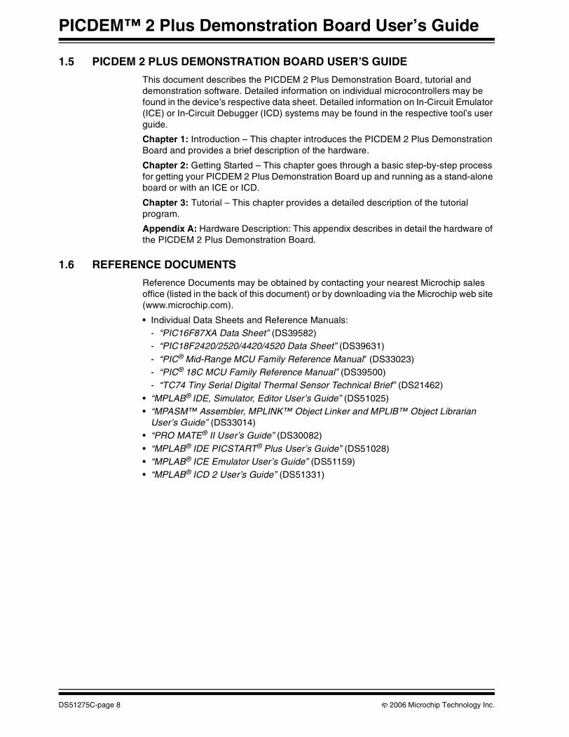
To use PICDEM 2 Plus Demonstration Board with an In-Circuit Emulator (ICE) or In-Circuit Debugger (ICD), refer to the tool’s user guide for instructions on how to power-up and configure the ICE/ICD, as well as how to connect to target boards (e.g., Figure 2-1).
FIGURE 2-1: PICDEM™ 2 PLUS CONNECTED TO MPLAB® ICD 2 USING USB
Configure the PICDEM 2 Plus Demonstration Board for the desired oscillator as described in Table 2-1. Refer to the ICE/ICD user’s guide for any oscillator configuration requirements.
TABLE 2-1: OSCILLATOR SELECTION
Oscillator Selection on PICDEM™ 2 Plus Demonstration Board
Modification on PICDEM 2 Plus Demonstration Board
RC J7 installed, Y1 and Y2 unpopulated
Crystal J7 removed, Y2 unpopulated, crystal in Y1, capacitors in C4 and C5
Canned Oscillator J7 removed, oscillator in Y2 (Y1, C4, C5 unpopulated)
Resonator (no internal capacitors) J7 removed, Y2 unpopulated, resonator in Y1, capacitors in C4 and C5
Resonator (with internal capacitors) J7 removed, Y2 unpopulated, resonator in Y1, C4 and C5 unpopulated
DS51275C-page 10 © 2006 Microchip Technology Inc.
PICDEM™ 2 PLUSDEMONSTRATION
BOARD USER’S GUIDE
Chapter 3. Tutorial
The tutorial program is preprogrammed into the sample device, (i.e., p16demo.hex for a PIC16 device and p18demo.hex for a PIC18 device). Also, this program is on the included CD-ROM program disk for user reference, (i.e., if the sample device has been reprogrammed with another program, the tutorial may be reprogrammed into the device).
For detailed information on the PICDEM 2 Plus Demonstration Board hardware, please refer to Appendix A.
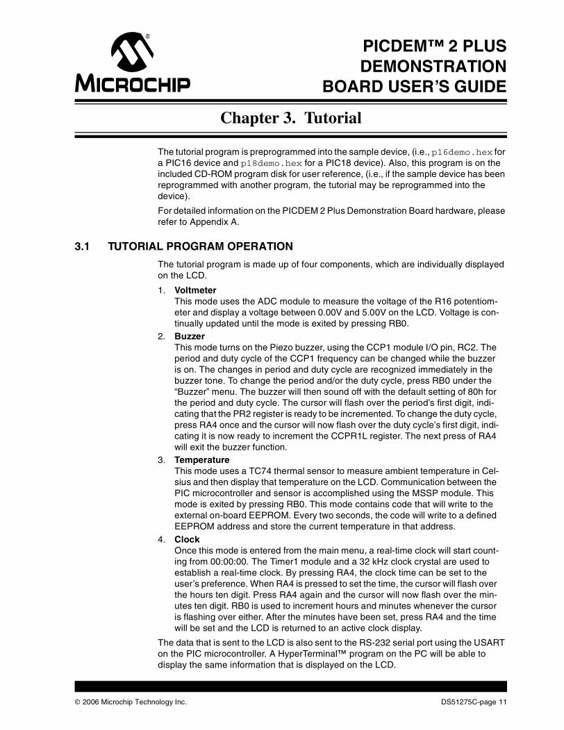
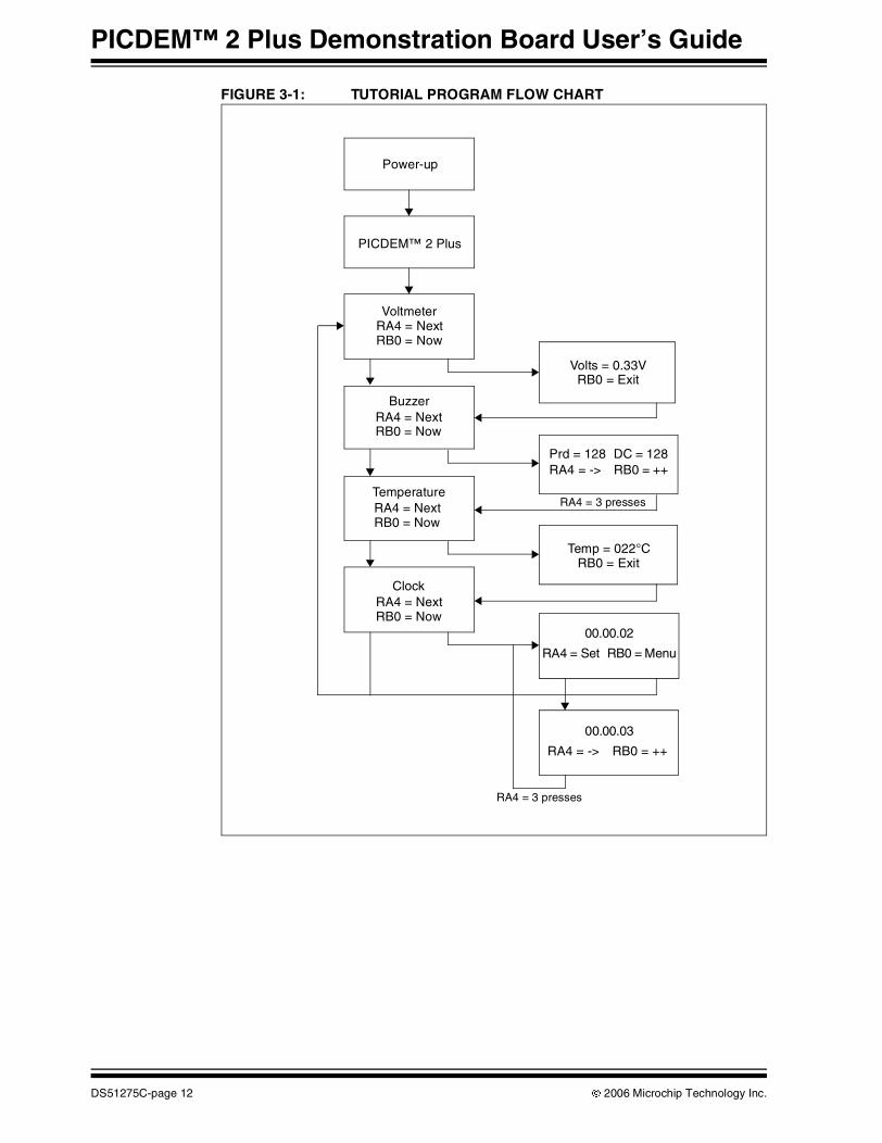
3.1 TUTORIAL PROGRAM OPERATION
The tutorial program is made up of four components, which are individually displayed on the LCD.
1. VoltmeterThis mode uses the ADC module to measure the voltage of the R16 potentiom-eter and display a voltage between 0.00V and 5.00V on the LCD. Voltage is con-tinually updated until the mode is exited by pressing RB0.
2. BuzzerThis mode turns on the Piezo buzzer, using the CCP1 module I/O pin, RC2. The period and duty cycle of the CCP1 frequency can be changed while the buzzer is on. The changes in period and duty cycle are recognized immediately in the buzzer tone. To change the period and/or the duty cycle, press RB0 under the “Buzzer” menu. The buzzer will then sound off with the default setting of 80h for the period and duty cycle. The cursor will flash over the period’s first digit, indi-cating that the PR2 register is ready to be incremented. To change the duty cycle, press RA4 once and the cursor will now flash over the duty cycle’s first digit, indi-cating it is now ready to increment the CCPR1L register. The next press of RA4 will exit the buzzer function.
3. TemperatureThis mode uses a TC74 thermal sensor to measure ambient temperature in Cel-sius and then display that temperature on the LCD. Communication between the PIC microcontroller and sensor is accomplished using the MSSP module. This mode is exited by pressing RB0. This mode contains code that will write to the external on-board EEPROM. Every two seconds, the code will write to a defined EEPROM address and store the current temperature in that address.
4. ClockOnce this mode is entered from the main menu, a real-time clock will start count-ing from 00:00:00. The Timer1 module and a 32 kHz clock crystal are used to establish a real-time clock. By pressing RA4, the clock time can be set to the user’s preference. When RA4 is pressed to set the time, the cursor will flash over the hours ten digit. Press RA4 again and the cursor will now flash over the min-utes ten digit. RB0 is used to increment hours and minutes whenever the cursor is flashing over either. After the minutes have been set, press RA4 and the time will be set and the LCD is returned to an active clock display.
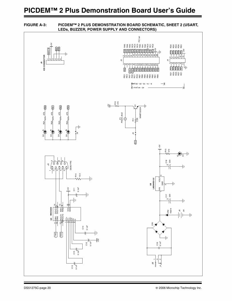
The data that is sent to the LCD is also sent to the RS-232 serial port using the USART on the PIC microcontroller. A HyperTerminal™ program on the PC will be able to display the same information that is displayed on the LCD.
© 2006 Microchip Technology Inc. DS51275C-page 11
PICDEM™ 2 Plus Demonstration Board User’s Guide
FIGURE 3-1: TUTORIAL PROGRAM FLOW CHART
Power-up
PICDEM™ 2 Plus
VoltmeterRA4 = NextRB0 = Now
Buzzer
Temperature
Clock
RA4 = NextRB0 = Now
RA4 = NextRB0 = Now
RA4 = NextRB0 = Now
Volts = 0.33VRB0 = Exit
Temp = 022°CRB0 = Exit
RA4 = 3 presses
RA4 = 3 presses
Prd = 128 DC = 128RA4 = -> RB0 = ++
00.00.02
RA4 = Set RB0 = Menu
00.00.03
RA4 = -> RB0 = ++
DS51275C-page 12 © 2006 Microchip Technology Inc.
Tutorial
3.2 SOURCE CODE AND APPLICATION NOTES
In addition to the assembled tutorial program (hex files), source code used to create these hex files is included on the PICDEM 2 Plus Demonstration Board CD-ROM. Both source code and related hex files are found in device-specific directories.
Application Notes are also included on the CD-ROM for additional examples of use.
For information on how to reprogram the device with new or modified code, or how to restore the tutorial program, please see Section 2.1 “PICDEM 2 Plus Demonstration Board as a Stand-Alone Board – Preprogrammed Device”.
© 2006 Microchip Technology Inc. DS51275C-page 13
PICDEM™ 2 Plus Demonstration Board User’s Guide
NOTES:
DS51275C-page 14 © 2006 Microchip Technology Inc.
PICDEM™ 2 PLUSDEMONSTRATION
BOARD USER’S GUIDE
Appendix A. Hardware Detail
The PICDEM 2 Plus Demonstration Board hardware is extremely simple and is intended to illustrate the ease of use of various PIC microcontrollers. The PICDEM 2 Plus Demonstration Board features the following hardware elements:
A.1 PROCESSOR SOCKETS
Although three sockets are provided, only one device may be used at a time.
• 18-pin socket• 28-pin socket• 40-pin socket
A.2 DISPLAY
Four red LEDs are connected to PORTB of each processor type. The PORTB pins are set high to light the LEDs. These LEDs may be disconnected from PORTB by removing jumper J6.
One green LED is provided to determine whether there is power to the PICDEM 2 Plus Demonstration Board board (LED on) or not (LED off).
A.3 POWER SUPPLY
There are three ways to supply power to the PICDEM 2 Plus Demonstration Board:
• A 9V battery can be plugged into J8.• A 9V, 100 mA unregulated AC or DC supply can be plugged into J2. A power
supply can be purchased through Microchip, Part #AC162039.• A +5V, 100 mA regulated DC supply can be connected to the hooks provided.
MPLAB ICE 2000 users have a regulated +5V power supply available in the logic probe connector and can easily connect to the hooks on PICDEM 2 Plus Demonstration Board (red probe to +5V and black probe to GND).
MPLAB ICD 2 users may use the ICD to power the target board to 5V, up to 200 mA, if the MPLAB ICD 2 is connected to the PC with a serial cable.
A.4 RS-232 SERIAL PORT
An RS-232 level shifting IC has been provided with all necessary hardware to support connection of an RS-232 host through the DB9 connector. The port is configured as DCE and can be connected to a PC using a straight-through cable.
The PIC16/PIC18 RX and TX pins are tied to the RX and TX lines of the MAX232A.
Note: The PICDEM 2 Plus Demonstration Board kit does not include a power supply.
© 2006 Microchip Technology Inc. DS51275C-page 15
PICDEM™ 2 Plus Demonstration Board User’s Guide
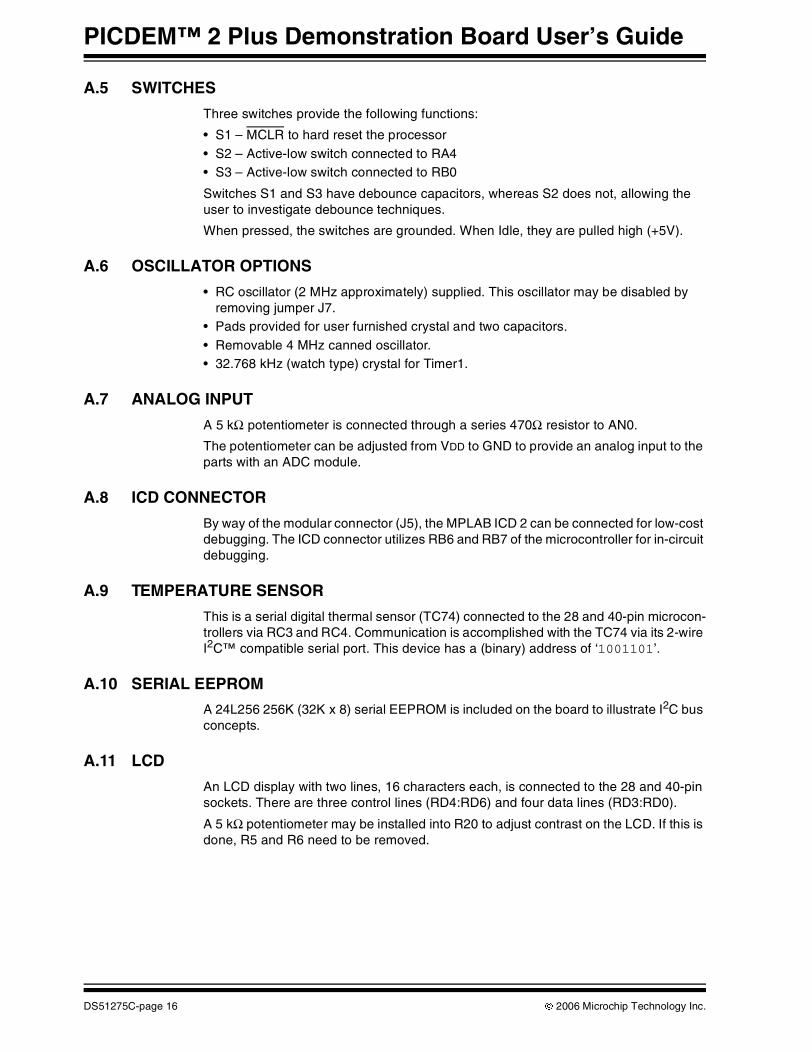
A.5 SWITCHES
Three switches provide the following functions:
• S1 – MCLR to hard reset the processor• S2 – Active-low switch connected to RA4• S3 – Active-low switch connected to RB0
Switches S1 and S3 have debounce capacitors, whereas S2 does not, allowing the user to investigate debounce techniques.
When pressed, the switches are grounded. When Idle, they are pulled high (+5V).
A.6 OSCILLATOR OPTIONS
• RC oscillator (2 MHz approximately) supplied. This oscillator may be disabled by removing jumper J7.
• Pads provided for user furnished crystal and two capacitors.• Removable 4 MHz canned oscillator.• 32.768 kHz (watch type) crystal for Timer1.
A.7 ANALOG INPUT
A 5 kΩ potentiometer is connected through a series 470Ω resistor to AN0.
The potentiometer can be adjusted from VDD to GND to provide an analog input to the parts with an ADC module.
A.8 ICD CONNECTOR
By way of the modular connector (J5), the MPLAB ICD 2 can be connected for low-cost debugging. The ICD connector utilizes RB6 and RB7 of the microcontroller for in-circuit debugging.
A.9 TEMPERATURE SENSOR
This is a serial digital thermal sensor (TC74) connected to the 28 and 40-pin microcon-trollers via RC3 and RC4. Communication is accomplished with the TC74 via its 2-wire I2C™ compatible serial port. This device has a (binary) address of ‘1001101’.
A.10 SERIAL EEPROM
A 24L256 256K (32K x 8) serial EEPROM is included on the board to illustrate I2C bus concepts.
A.11 LCD
An LCD display with two lines, 16 characters each, is connected to the 28 and 40-pin sockets. There are three control lines (RD4:RD6) and four data lines (RD3:RD0).
A 5 kΩ potentiometer may be installed into R20 to adjust contrast on the LCD. If this is done, R5 and R6 need to be removed.
DS51275C-page 16 © 2006 Microchip Technology Inc.
Hardware Detail
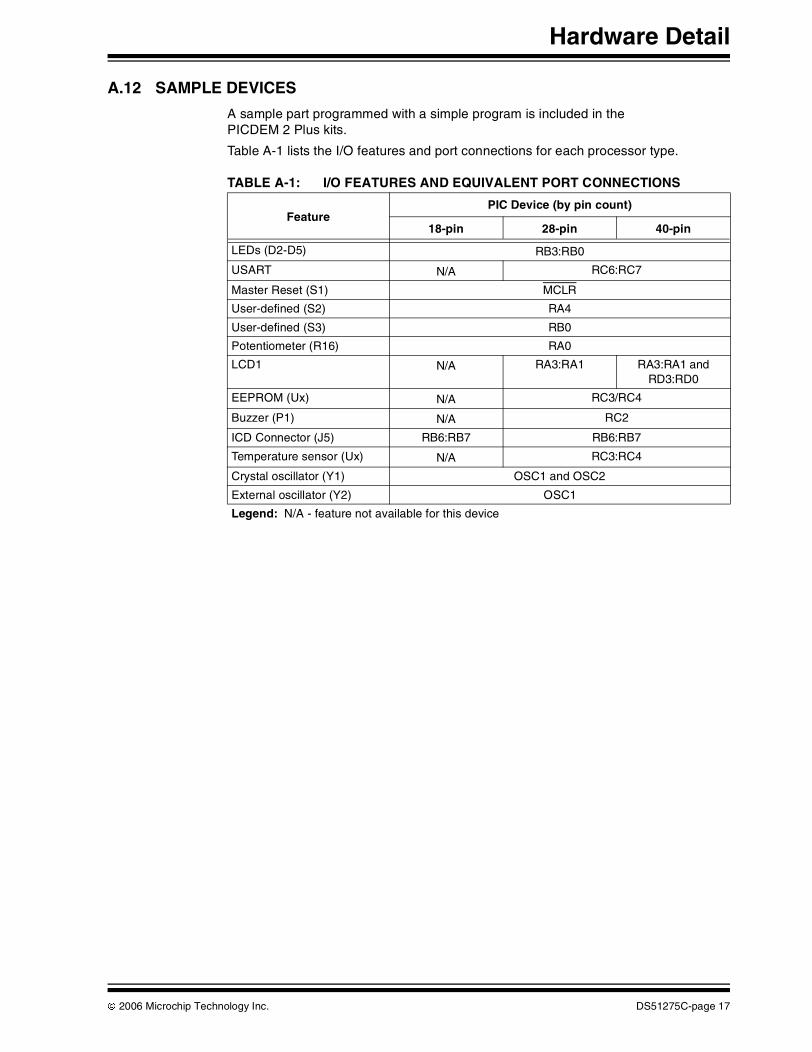
A.12 SAMPLE DEVICES
A sample part programmed with a simple program is included in the PICDEM 2 Plus kits.
Table A-1 lists the I/O features and port connections for each processor type.
TABLE A-1: I/O FEATURES AND EQUIVALENT PORT CONNECTIONS
FeaturePIC Device (by pin count)
18-pin 28-pin 40-pin
LEDs (D2-D5) RB3:RB0
USART N/A RC6:RC7
Master Reset (S1) MCLR
User-defined (S2) RA4
User-defined (S3) RB0
Potentiometer (R16) RA0
LCD1 N/A RA3:RA1 RA3:RA1 and RD3:RD0
EEPROM (Ux) N/A RC3/RC4
Buzzer (P1) N/A RC2
ICD Connector (J5) RB6:RB7 RB6:RB7
Temperature sensor (Ux) N/A RC3:RC4
Crystal oscillator (Y1) OSC1 and OSC2
External oscillator (Y2) OSC1
Legend: N/A - feature not available for this device
© 2006 Microchip Technology Inc. DS51275C-page 17
PICDEM™ 2 Plus Demonstration Board User’s Guide
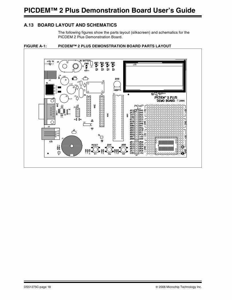
A.13 BOARD LAYOUT AND SCHEMATICS
The following figures show the parts layout (silkscreen) and schematics for the PICDEM 2 Plus Demonstration Board.
FIGURE A-1: PICDEM™ 2 PLUS DEMONSTRATION BOARD PARTS LAYOUT
DS51275C-page 18 © 2006 Microchip Technology Inc.
Hardware Detail
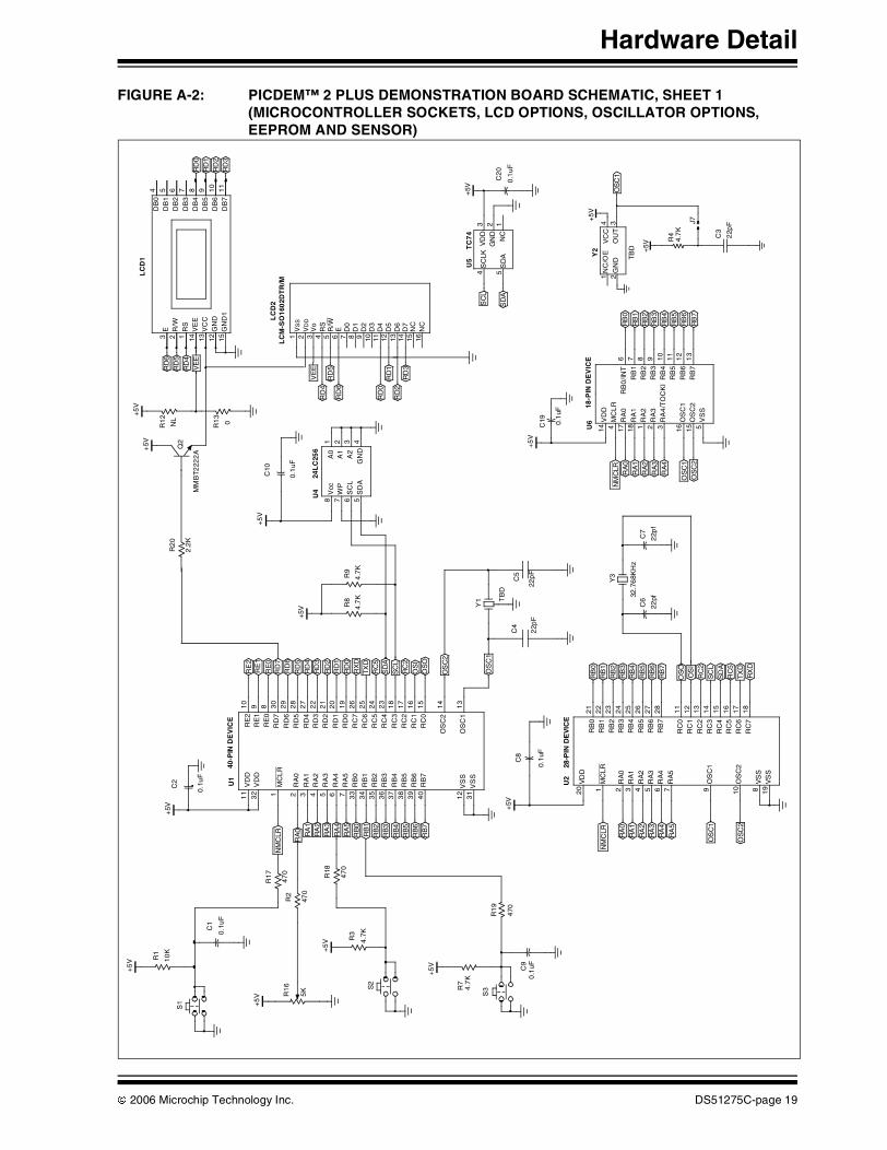
FIGURE A-2: PICDEM™ 2 PLUS DEMONSTRATION BOARD SCHEMATIC, SHEET 1 (MICROCONTROLLER SOCKETS, LCD OPTIONS, OSCILLATOR OPTIONS, EEPROM AND SENSOR)
OS
O
RC
2S
CL
RC
5T
XD
RD
0
RD
1
RD
3R
D4
RD
6R
D7
RE
1R
E2
+5
V
+5
V
RA
0
+5V
OS
C2
OS
C1
SD
A
OS
I
RX
D
RD
2
RE
0
RD
5
4.7
K
R8
+5V
+5
V
10
K
R1
0.1
uF
C2
RB
7
RB
5R
B4
RB
2R
B1
RA
5R
A4
RA
2R
A1
RB
6
RB
3
RB
0
RA
3
47
0
R18
47
0
R1
7
4.7
K
R9
0.1
uF
C10
S2
+5
V 5K
R1
6
C1
0.1
uF
S1
C4
22p
F
C5
22p
F
Y1 T
BD
4.7
K
R3
31
VS
S
32
VD
D
11
VD
D
1M
CL
R
2R
A0
3R
A1
4R
A2
5R
A3
6R
A4
7R
A5
33
RB
03
4R
B1
35
RB
23
6R
B3
37
RB
43
8R
B5
39
RB
64
0R
B7
12
VS
S1
3O
SC
1
14
OS
C2
15
RC
0
16
RC
1
17
RC
2
18
RC
3
23
RC
4
24
RC
5
25
RC
6
26
RC
7
19
RD
0
20
RD
1
21
RD
2
22
RD
3
27
RD
4
28
RD
5
29
RD
6
30
RD
7
10
RE
29
RE
18
RE
0
40-P
IN D
EV
ICE
U1
470
R2
4G
ND
1A
02
A1
3A
25
SD
A
6S
CL
7W
P
8V
cc
U4
24L
C25
6
RA
5
RA
4
RA
2
RA
1
RX
D
RC
5S
DA
RC
2
OS
I
RB
7
RB
5
RB
4
RB
2
RB
1
RA
3
RA
0
+5V
TX
D
SC
L
RB
6
OS
O
RB
0
RB
3
22pf
C6
22p
f
C7
32.7
68K
Hz
Y3
1M
CLR
2R
A0
3R
A1
4R
A2
5R
A3
6R
A4
7R
A5
20
VD
D
22
RB
1
24
RB
32
5R
B4
26
RB
52
7R
B6
28
RB
7
23
RB
2
21
RB
0
11
RC
0
8V
SS
19
VS
S
10
OS
C2
9O
SC
1
12
RC
11
3R
C2
14
RC
31
5R
C4
16
RC
51
7R
C6
18
RC
7
U2
28-P
IN D
EV
ICE
0.1
uF
C8
RD
3
RD
5RD
4
RD
5
+5
V+
5V
RD
1
VE
EVE
E
RD
6N
L
R1
2
0R1
3
RD
2
RD
0
RD
4
RD
2R
D1
RD
6
RD
3
RD
0
Q2
MM
BT
222
2A
16N
C
13D
6
10D
3
7D
0
4R
S
1V
SS
14D
7
11D
4
8D
1
12D
5
9D
2
6E
5R
/W
2V
DD
3V
o
15N
C
LC
M-S
O1
602D
TR
/M
2.2
K
R2
0
12G
ND
1R
S
15G
ND
1
13V
CC
14V
EE
2R
/W
3E
10
DB
6
7D
B3
4D
B0
8D
B4
9D
B5
11
DB
7
5D
B1
6D
B2
LC
D1
OS
C2
RA
4
RA
2R
A1
RB
7
RB
5R
B4
RB
2R
B1
OS
C1
RA
0
RA
3
+5
V
RB
6
RB
0
RB
3
NM
CLR
0.1
uF
C19
14V
DD
4M
CL
R17
RA
018
RA
11
RA
22
RA
33
RA
4/T
OC
KI
16O
SC
115
OS
C2
5V
SS
6R
B0
/INT
7R
B1
8R
B2
9R
B3
10
RB
41
1R
B5
12
RB
61
3R
B7
U6
18-P
IN D
EV
ICE
470
R1
9S
3
C9
0.1
uF
+5
V
4.7
KR
7
SC
L
SD
A
+5V
C2
0
0.1
uF
3V
DD
2G
ND
1N
C
4S
CLK
5S
DA
U5
TC
74
OS
C1
J7+5
V
+5V
R4
4.7
K
C3
22p
F4V
CC
3O
UT
2G
ND
1N
C/O
E
TB
D
Y2
LC
D2
NM
CLR
NM
CLR
OS
C2
OS
C1
© 2006 Microchip Technology Inc. DS51275C-page 19
PICDEM™ 2 Plus Demonstration Board User’s Guide
FIGURE A-3: PICDEM™ 2 PLUS DEMONSTRATION BOARD SCHEMATIC, SHEET 2 (USART, LEDs, BUZZER, POWER SUPPLY AND CONNECTORS)
RX
D
TX
D
+5
VR
B3
RB
1
RB
2
RB
0
C1
4
0.1
uF
C1
5
0.1
uF
C1
1
0.1
uF
21 3 4
6 7 8 95
J1
DE
9S-F
RS
+5V
C1
2
0.1
uF
C1
3
0.1u
FJ6
R24
470
R23
470
R22
470
R21
470
10.0
R1
4
D4
D2
D3
D5
11
DIN
11
0D
IN2
12
RO
UT
19
RO
UT
2
3C
1-1
C1+
5C
2-4
C2+
6V
-2
V+
15
GN
D1
6V
CC
8R
IN2
13
RIN
1
7D
OU
T2
14
DO
UT
1
U3
MA
X3
232
PIC
tai
l
40 - 44 pins
8 - 14 - 18 - 20 - 28 pins
RB
7
RE
1R
E1
RD
7R
D7
RD
3R
D3
RD
1R
D1
RB
1R
B1
RB
2R
B2
RB
4R
B4
RB
5R
B5
RB
7R
B7
RC
6T
XD
RA
6O
SC
2
RA
7O
SC
1
RE
2R
E2
RE
0
RD
6
RD
2
RD
0
RC
2
OS
OR
A2
RA
0S
CL
RC
5R
A3
RA
5
RC
2
RC
0R
A2
RA
0R
C3
RC
5R
A3
RA
5
RB
6
+5V
47
0
R1
5
RD
5R
D5
RB
0R
B0
RB
3
RB
6R
B6
RB
3
RC
7
RE
3
RX
D
RD
4 +5V
RA
1
OS
I
RA
4
SD
A
RC
1
RA
1
RC
4
RA
4
1 2 3 4 65
J5
D1
+5V
ICD
CO
NN
EC
TO
R
NM
CL
R
RE
0
RD
6
RD
2
RD
01N
914
CR
2
RD
4
+5
VC
16
0.1u
F
1 3 2
J2
J8 9V
3V
OU
T1
VIN
2GN
D
U8
LM
294
0S-5
.0
12
3 5 7
4 6 8
11
129
10
J4C
18 22
0
C1
7
220
56
78
910
11
121
314
15
16
17
181
920
21
22
23
242
526
27
28
12
34
J3
CR
1
RC
22.
2K
R11
470
R10
+5V
J9
PIE
ZO
_BU
ZP
1
Q1
MM
BT
2222
A
DS51275C-page 20 © 2006 Microchip Technology Inc.
PICDEM™ 2 PLUSDEMONSTRATION
BOARD USER’S GUIDE
Index
AA/D Input ...............................................................6, 16
BBoard ............................................................ 5, 6, 9, 15
Parts Layout...................................................... 18Power Supply.................................................9, 15Schematics ....................................................... 18Silkscreen ......................................................... 18
Buzzer ...................................................................... 11Buzzer, Piezo ............................................................. 6
CClock ........................................................................ 11Customer Support ...................................................... 4
DDemonstration Board. See BoardDemonstration Programs. See Sample Programs.Documentation
Conventions ........................................................ 2Layout ................................................................. 1
EEEPROM, Serial ...................................................6, 16
HHardware ................................................................. 15
IICD Connector ......................................................... 16Internet Address......................................................... 3
KKit Components ......................................................... 5
LLCD.......................................................................6, 16LEDs
Green Power..................................................6, 15Red Display ...............................................6, 9, 15
MMicrochip Internet Web Site ....................................... 3MPASM Assembler .................................................... 9MPASM Assembler User’s Guide with MPLINK Linker
and MPLIB Librarian............................................... 8MPLAB C18 ............................................................... 9MPLAB ICD 2........................................ 5, 9, 10, 15, 16MPLAB ICD 2 Quick Start Guide ............................... 8MPLAB ICE.....................................................5, 10, 15MPLAB ICE User’s Guide .......................................... 8MPLAB IDE................................................................ 9
MPLAB IDE User’s Guide .......................................... 8
OOscillator Options..................................................... 16Oscillator Selection .................................................. 10
PPIC16F87X Data Sheet.............................................. 8PIC16XXXX................................................................ 5
Tutorial Program ............................................... 11PIC18FXX2 Data Sheet ............................................. 8PIC18XXXX................................................................ 5
Tutorial Program ............................................... 11PICDEM 2 Plus Board. See BoardPICDEM 2 Plus Kit. See Kit Components.PICSTART® Plus....................................................... 9PICSTART® Plus User’s Guide ................................. 8Piezo Buzzer .............................................................. 6PRO MATE® II........................................................... 9PRO MATE® II User’s Guide ..................................... 8Push Buttons. See Switches.
RReading, Recommended ........................................... 3Reference Documents ............................................... 8RS-232 ................................................................. 6, 15
SSample Devices ................................................5, 7, 17Sample Programs .................................................. 5, 7Sockets .................................................................... 15Switches............................................................... 6, 16
TTC74 .......................................................................... 6TC74 Data Sheet ....................................................... 8Temperature............................................................. 11Temperature Sensor ................................................ 16
TC74 ................................................................. 16Tutorial ..................................................................... 11Tutorial Program
Flow Chart......................................................... 12Source Code, Application Notes ....................... 13
VVoltmeter.................................................................. 11
WWWW Address........................................................... 3
© 2006 Microchip Technology Inc. DS51275C-page 21
DS51275C-page 22 © 2006 Microchip Technology Inc.
AMERICASCorporate Office2355 West Chandler Blvd.Chandler, AZ 85224-6199Tel: 480-792-7200 Fax: 480-792-7277Technical Support: http://support.microchip.comWeb Address: www.microchip.com
AtlantaAlpharetta, GA Tel: 770-640-0034 Fax: 770-640-0307
BostonWestborough, MA Tel: 774-760-0087 Fax: 774-760-0088
ChicagoItasca, IL Tel: 630-285-0071 Fax: 630-285-0075
DallasAddison, TX Tel: 972-818-7423 Fax: 972-818-2924
DetroitFarmington Hills, MI Tel: 248-538-2250Fax: 248-538-2260
KokomoKokomo, IN Tel: 765-864-8360Fax: 765-864-8387
Los AngelesMission Viejo, CA Tel: 949-462-9523 Fax: 949-462-9608
Santa ClaraSanta Clara, CA Tel: 408-961-6444Fax: 408-961-6445
TorontoMississauga, Ontario, CanadaTel: 905-673-0699 Fax: 905-673-6509
ASIA/PACIFICAsia Pacific OfficeSuites 3707-14, 37th FloorTower 6, The GatewayHabour City, KowloonHong KongTel: 852-2401-1200Fax: 852-2401-3431
Australia - SydneyTel: 61-2-9868-6733Fax: 61-2-9868-6755
China - BeijingTel: 86-10-8528-2100 Fax: 86-10-8528-2104
China - ChengduTel: 86-28-8665-5511Fax: 86-28-8665-7889
China - FuzhouTel: 86-591-8750-3506 Fax: 86-591-8750-3521
China - Hong Kong SARTel: 852-2401-1200 Fax: 852-2401-3431
China - QingdaoTel: 86-532-8502-7355Fax: 86-532-8502-7205
China - ShanghaiTel: 86-21-5407-5533 Fax: 86-21-5407-5066
China - ShenyangTel: 86-24-2334-2829Fax: 86-24-2334-2393
China - ShenzhenTel: 86-755-8203-2660 Fax: 86-755-8203-1760
China - ShundeTel: 86-757-2839-5507 Fax: 86-757-2839-5571
China - WuhanTel: 86-27-5980-5300Fax: 86-27-5980-5118
China - XianTel: 86-29-8833-7250Fax: 86-29-8833-7256
ASIA/PACIFICIndia - BangaloreTel: 91-80-4182-8400 Fax: 91-80-4182-8422
India - New DelhiTel: 91-11-4160-8631Fax: 91-11-4160-8632
India - PuneTel: 91-20-2566-1512Fax: 91-20-2566-1513
Japan - YokohamaTel: 81-45-471- 6166 Fax: 81-45-471-6122
Korea - GumiTel: 82-54-473-4301Fax: 82-54-473-4302
Korea - SeoulTel: 82-2-554-7200Fax: 82-2-558-5932 or 82-2-558-5934
Malaysia - PenangTel: 60-4-646-8870Fax: 60-4-646-5086
Philippines - ManilaTel: 63-2-634-9065Fax: 63-2-634-9069
SingaporeTel: 65-6334-8870Fax: 65-6334-8850
Taiwan - Hsin ChuTel: 886-3-572-9526Fax: 886-3-572-6459
Taiwan - KaohsiungTel: 886-7-536-4818Fax: 886-7-536-4803
Taiwan - TaipeiTel: 886-2-2500-6610 Fax: 886-2-2508-0102
Thailand - BangkokTel: 66-2-694-1351Fax: 66-2-694-1350
EUROPEAustria - WelsTel: 43-7242-2244-39Fax: 43-7242-2244-393Denmark - CopenhagenTel: 45-4450-2828 Fax: 45-4485-2829
France - ParisTel: 33-1-69-53-63-20 Fax: 33-1-69-30-90-79
Germany - MunichTel: 49-89-627-144-0 Fax: 49-89-627-144-44
Italy - Milan Tel: 39-0331-742611 Fax: 39-0331-466781
Netherlands - DrunenTel: 31-416-690399 Fax: 31-416-690340
Spain - MadridTel: 34-91-708-08-90Fax: 34-91-708-08-91
UK - WokinghamTel: 44-118-921-5869Fax: 44-118-921-5820
WORLDWIDE SALES AND SERVICE
10/19/06