Embed Size (px)
Citation preview
2013 Microchip Technology Inc. DS70005147A
PIC32MZ EmbeddedConnectivity (EC) Starter Kit
User’s Guide
DS70005147A-page 2 2013 Microchip Technology Inc.
Information contained in this publication regarding deviceapplications and the like is provided only for your convenienceand may be superseded by updates. It is your responsibility toensure that your application meets with your specifications.MICROCHIP MAKES NO REPRESENTATIONS ORWARRANTIES OF ANY KIND WHETHER EXPRESS ORIMPLIED, WRITTEN OR ORAL, STATUTORY OROTHERWISE, RELATED TO THE INFORMATION,INCLUDING BUT NOT LIMITED TO ITS CONDITION,QUALITY, PERFORMANCE, MERCHANTABILITY ORFITNESS FOR PURPOSE. Microchip disclaims all liabilityarising from this information and its use. Use of Microchipdevices in life support and/or safety applications is entirely atthe buyer’s risk, and the buyer agrees to defend, indemnify andhold harmless Microchip from any and all damages, claims,suits, or expenses resulting from such use. No licenses areconveyed, implicitly or otherwise, under any Microchipintellectual property rights.
Note the following details of the code protection feature on Microchip devices:
• Microchip products meet the specification contained in their particular Microchip Data Sheet.
• Microchip believes that its family of products is one of the most secure families of its kind on the market today, when used in the intended manner and under normal conditions.
• There are dishonest and possibly illegal methods used to breach the code protection feature. All of these methods, to our knowledge, require using the Microchip products in a manner outside the operating specifications contained in Microchip’s Data Sheets. Most likely, the person doing so is engaged in theft of intellectual property.
• Microchip is willing to work with the customer who is concerned about the integrity of their code.
• Neither Microchip nor any other semiconductor manufacturer can guarantee the security of their code. Code protection does not mean that we are guaranteeing the product as “unbreakable.”
Code protection is constantly evolving. We at Microchip are committed to continuously improving the code protection features of ourproducts. Attempts to break Microchip’s code protection feature may be a violation of the Digital Millennium Copyright Act. If such actsallow unauthorized access to your software or other copyrighted work, you may have a right to sue for relief under that Act.
Microchip received ISO/TS-16949:2009 certification for its worldwide headquarters, design and wafer fabrication facilities in Chandler and Tempe, Arizona; Gresham, Oregon and design centers in California and India. The Company’s quality system processes and procedures are for its PIC® MCUs and dsPIC® DSCs, KEELOQ® code hopping devices, Serial EEPROMs, microperipherals, nonvolatile memory and analog products. In addition, Microchip’s quality system for the design and manufacture of development systems is ISO 9001:2000 certified.
QUALITY MANAGEMENT SYSTEM CERTIFIED BY DNV
== ISO/TS 16949 ==
Trademarks
The Microchip name and logo, the Microchip logo, dsPIC, FlashFlex, KEELOQ, KEELOQ logo, MPLAB, PIC, PICmicro, PICSTART, PIC32 logo, rfPIC, SST, SST Logo, SuperFlash and UNI/O are registered trademarks of Microchip Technology Incorporated in the U.S.A. and other countries.
FilterLab, Hampshire, HI-TECH C, Linear Active Thermistor, MTP, SEEVAL and The Embedded Control Solutions Company are registered trademarks of Microchip Technology Incorporated in the U.S.A.
Silicon Storage Technology is a registered trademark of Microchip Technology Inc. in other countries.
Analog-for-the-Digital Age, Application Maestro, BodyCom, chipKIT, chipKIT logo, CodeGuard, dsPICDEM, dsPICDEM.net, dsPICworks, dsSPEAK, ECAN, ECONOMONITOR, FanSense, HI-TIDE, In-Circuit Serial Programming, ICSP, Mindi, MiWi, MPASM, MPF, MPLAB Certified logo, MPLIB, MPLINK, mTouch, Omniscient Code Generation, PICC, PICC-18, PICDEM, PICDEM.net, PICkit, PICtail, REAL ICE, rfLAB, Select Mode, SQI, Serial Quad I/O, Total Endurance, TSHARC, UniWinDriver, WiperLock, ZENA and Z-Scale are trademarks of Microchip Technology Incorporated in the U.S.A. and other countries.
SQTP is a service mark of Microchip Technology Incorporated in the U.S.A.
GestIC and ULPP are registered trademarks of Microchip Technology Germany II GmbH & Co. & KG, a subsidiary of Microchip Technology Inc., in other countries.
All other trademarks mentioned herein are property of their respective companies.
© 2013, Microchip Technology Incorporated, Printed in the U.S.A., All Rights Reserved.
Printed on recycled paper.
ISBN: 978-1-62077-646-9

PIC32MZ EMBEDDEDCONNECTIVITY (EC)
STARTER KIT USER’S GUIDE
Table of Contents
Preface ........................................................................................................................... 5
Chapter 1. Introduction1.1 Kit Contents .................................................................................................. 111.2 Starter Kit Functionality and Features .......................................................... 12
Chapter 2. Hardware2.1 Hardware Features ....................................................................................... 15
Appendix A. Board Layout and SchematicsA.1 Block Diagram .............................................................................................. 19A.2 Board Layout ................................................................................................ 20A.3 Schematics .................................................................................................. 22
Appendix B. Bill of Materials....................................................................................... 26
Worldwide Sales and Service .................................................................................... 32
2013 Microchip Technology Inc. DS70005147A-page 3

PIC32MZ Embedded Connectivity (EC) Starter Kit User’s Guide
NOTES:
DS70005147A-page 4 2013 Microchip Technology Inc.

PIC32MZ EMBEDDEDCONNECTIVITY (EC)
STARTER KIT USER’S GUIDE
Preface
INTRODUCTION
This chapter contains general information that will be useful to know before using the PIC32MZ Embedded Connectivity (EC) Starter Kit. Items discussed in this chapter include:
• Document Layout• Conventions Used in this Guide• Recommended Reading• The Microchip Web Site• Development Systems Customer Change Notification Service• Customer Support• Document Revision History
DOCUMENT LAYOUT
This document describes how to use the PIC32MZ Embedded Connectivity (EC) Starter Kit (also referred to as “starter kit”) as a development tool to emulate and debug firmware on a target board. This user’s guide is composed of the following chapters:
• Chapter 1. “Introduction” provides a brief overview of the starter kit, highlighting its features and uses.
• Chapter 2. “Hardware” provides the hardware descriptions of the starter kit.
• Appendix A. “Board Layout and Schematics” provides a block diagram, board layouts, and detailed schematics of the starter kit.
• Appendix B. “Bill of Materials” provides the bill of materials for the components used in the design and manufacture of the starter kit.
NOTICE TO CUSTOMERS
All documentation becomes dated, and this manual is no exception. Microchip tools and documentation are constantly evolving to meet customer needs, so some actual dialogs and/or tool descriptions may differ from those in this document. Please refer to our web site (www.microchip.com) to obtain the latest documentation available.
Documents are identified with a “DS” number. This number is located on the bottom of each page, in front of the page number. The numbering convention for the DS number is “DSXXXXXXXXA”, where “XXXXXXXX” is the document number and “A” is the revision level of the document.
For the most up-to-date information on development tools, see the MPLAB® IDE online help. Select the Help menu, and then Topics to open a list of available online help files.
2013 Microchip Technology Inc. DS70005147A-page 5
PIC32MZ Embedded Connectivity (EC) Starter Kit User’s Guide
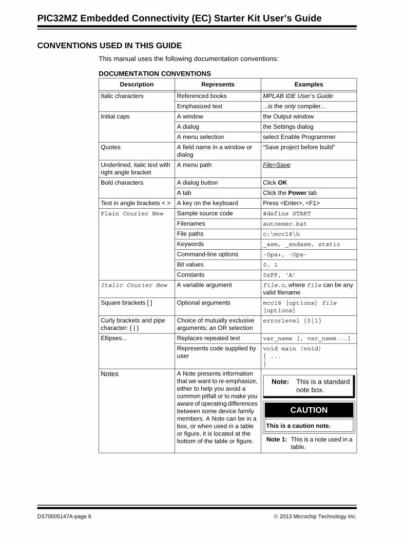
CONVENTIONS USED IN THIS GUIDE
This manual uses the following documentation conventions:
DOCUMENTATION CONVENTIONS
Description Represents Examples
Italic characters Referenced books MPLAB IDE User’s Guide
Emphasized text ...is the only compiler...
Initial caps A window the Output window
A dialog the Settings dialog
A menu selection select Enable Programmer
Quotes A field name in a window or dialog
“Save project before build”
Underlined, italic text with right angle bracket
A menu path File>Save
Bold characters A dialog button Click OK
A tab Click the Power tab
Text in angle brackets < > A key on the keyboard Press <Enter>, <F1>
Plain Courier New Sample source code #define START
Filenames autoexec.bat
File paths c:\mcc18\h
Keywords _asm, _endasm, static
Command-line options -Opa+, -Opa-
Bit values 0, 1
Constants 0xFF, ‘A’
Italic Courier New A variable argument file.o, where file can be any valid filename
Square brackets [ ] Optional arguments mcc18 [options] file [options]
Curly brackets and pipe character: { | }
Choice of mutually exclusive arguments; an OR selection
errorlevel {0|1}
Ellipses... Replaces repeated text var_name [, var_name...]
Represents code supplied by user
void main (void){ ...}
Notes A Note presents information that we want to re-emphasize, either to help you avoid a common pitfall or to make you aware of operating differences between some device family members. A Note can be in a box, or when used in a table or figure, it is located at the bottom of the table or figure. Note 1: This is a note used in a
table.
Note: This is a standard note box.
CAUTION
This is a caution note.
DS70005147A-page 6 2013 Microchip Technology Inc.
Preface
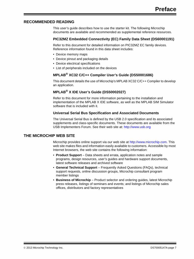
RECOMMENDED READING
This user’s guide describes how to use the starter kit. The following Microchip documents are available and recommended as supplemental reference resources.
PIC32MZ Embedded Connectivity (EC) Family Data Sheet (DS60001191)
Refer to this document for detailed information on PIC32MZ EC family devices. Reference information found in this data sheet includes:
• Device memory maps
• Device pinout and packaging details
• Device electrical specifications
• List of peripherals included on the devices
MPLAB® XC32 C/C++ Compiler User’s Guide (DS50001686)
This document details the use of Microchip’s MPLAB XC32 C/C++ Compiler to develop an application.
MPLAB® X IDE User’s Guide (DS50002027)
Refer to this document for more information pertaining to the installation and implementation of the MPLAB X IDE software, as well as the MPLAB SIM Simulator software that is included with it.
Universal Serial Bus Specification and Associated Documents
The Universal Serial Bus is defined by the USB 2.0 specification and its associated supplements and class-specific documents. These documents are available from the USB Implementers Forum. See their web site at: http://www.usb.org
THE MICROCHIP WEB SITE
Microchip provides online support via our web site at http://www.microchip.com. This web site makes files and information easily available to customers. Accessible by most Internet browsers, the web site contains the following information:
• Product Support – Data sheets and errata, application notes and sample programs, design resources, user’s guides and hardware support documents, latest software releases and archived software
• General Technical Support – Frequently Asked Questions (FAQs), technical support requests, online discussion groups, Microchip consultant program member listings
• Business of Microchip – Product selector and ordering guides, latest Microchip press releases, listings of seminars and events; and listings of Microchip sales offices, distributors and factory representatives
2013 Microchip Technology Inc. DS70005147A-page 7

PIC32MZ Embedded Connectivity (EC) Starter Kit User’s Guide
DEVELOPMENT SYSTEMS CUSTOMER CHANGE NOTIFICATION SERVICE
Microchip’s customer notification service helps keep customers current on Microchip products. Subscribers will receive e-mail notification whenever there are changes, updates, revisions or errata related to a specified product family or development tool of interest.
To register, access the Microchip web site at www.microchip.com, click on Customer Change Notification and follow the registration instructions.
The Development Systems product group categories are:
• Compilers – The latest information on Microchip C compilers and other language tools
• Emulators – The latest information on the Microchip in-circuit emulator, MPLAB REAL ICE™
• In-Circuit Debuggers – The latest information on the Microchip in-circuit debugger, MPLAB ICD 3
• MPLAB X IDE – The latest information on Microchip MPLAB X IDE, the Windows® Integrated Development Environment for development systems tools
• Programmers – The latest information on Microchip programmers including the PICkit™ 3 development programmer
CUSTOMER SUPPORT
Users of Microchip products can receive assistance through several channels:
• Distributor or Representative
• Local Sales Office
• Field Application Engineer (FAE)
• Technical Support
Customers should contact their distributor, representative or field application engineer (FAE) for support. Local sales offices are also available to help customers. A listing of sales offices and locations is included in the back of this document.
Technical support is available through the web site at: http://support.microchip.com
DS70005147A-page 8 2013 Microchip Technology Inc.

Preface
DOCUMENT REVISION HISTORY
Revision A (November 2013)
This is the initial release of this document.
2013 Microchip Technology Inc. DS70005147A-page 9

PIC32MZ Embedded Connectivity (EC) Starter Kit User’s Guide
NOTES:
DS70005147A-page 10 2013 Microchip Technology Inc.

PIC32MZ EMBEDDEDCONNECTIVITY (EC)
STARTER KIT USER’S GUIDE
Chapter 1. Introduction
Thank you for purchasing a Microchip Technology PIC32MZ Embedded Connectivity (EC) Starter Kit. This board provides a low-cost, modular development system for Microchip’s line of 32-bit microcontrollers.
The starter kit comes preloaded with demonstration software for the user to explore the new features of the PIC32MZ EC family of devices. It is also expandable through a modular expansion interface, which allows the user to extend its functionality. The starter kit also supplies on-board circuitry for full debug and programming capabilities.
This chapter covers the following topics:
• Kit Contents• Starter Kit Functionality and Features
The preprogrammed example code on the PIC32MZ EC family MCU is available for download from the Microchip web site at http://www.microchip.com. All project files have been included so that the code may be used directly to restore the PIC32MZ EC family MCU on the starter kit to its original state (i.e., if the sample device has been reprogrammed with another program) or so you can use the tutorial code as a platform for further experimentation.
1.1 KIT CONTENTS
The PIC32MZ Embedded Connectivity (EC) Starter Kit contains the following items:
• PIC32MZ Embedded Connectivity (EC) Starter Kit development board• SMSC 8870A Ethernet PHY daughter board
• USB mini-B to full-sized A cable – USB debug cable to debug and power the starter kit development board
• USB micro-B to full-sized A cable – PIC32 USB cable to communicate with the PIC32 USB port
• RJ-45 CAT5 Ethernet patch cable – Ethernet CAT5 cable to communicate with the PIC32 Ethernet port
Note: If you are missing any part of a kit, contact a Microchip sales office for assis-tance. A list of Microchip offices for sales and service is provided on the back page of this document.
2013 Microchip Technology Inc. DS70005147A-page 11

PIC32MZ Embedded Connectivity (EC) Starter Kit User’s Guide
1.2 STARTER KIT FUNCTIONALITY AND FEATURESRepresentations of the layout of the PIC32MZ Embedded Connectivity (EC) Starter Kit are shown in Figure 1-1 and Figure 1-2.
The top assembly of the board includes these key features, as indicated in Figure 1-1:
1. PIC32MZ2048ECH144-I/PH (non-crypto) or PIC32MZ2048ECM144-I/PH (crypto) 32-bit microcontroller.
2. Green power indicator LED.3. On-board crystal or oscillator for precision microcontroller clocking (12 MHz).4. USB connectivity for on-board debugger communications.5. Green debug indicator LED.6. Three push button switches for user-defined inputs.7. Three user-defined indicator LEDs.8. USB Type A receptacle connectivity for PIC32 host-based applications.9. HOST mode power jumper.10. Daughter board connectors for flexible Ethernet PHY options.11. 32 kHz oscillator for RTCC and Timer1 (optional).12. External 2 GB SQI memory for expanded memory applications.13. Jumper for using or disconnecting the on-board debugger.
For details on these features, refer to Chapter 2. “Hardware”.
FIGURE 1-1: PIC32MZ EMBEDDED CONNECTIVITY (EC) STARTER KIT LAYOUT (TOP VIEW)
Note: When running self-powered USB device applications, open the jumper JP1 to prevent possibly back-feeding voltage onto the VBUS from one port on the host to another (or from one host to another).
4
5
6
1
3
10
2
9
811
7
6
6
7
7
1213
DS70005147A-page 12 2013 Microchip Technology Inc.
Introduction
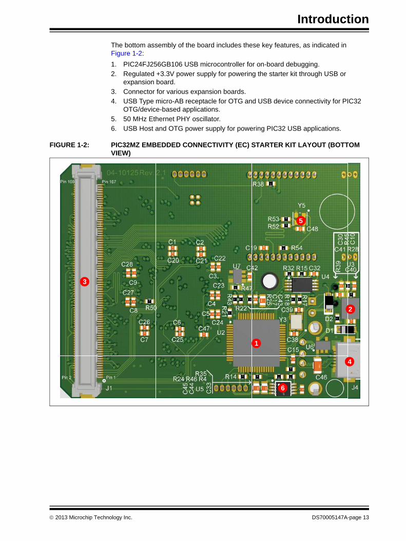
The bottom assembly of the board includes these key features, as indicated in Figure 1-2:
1. PIC24FJ256GB106 USB microcontroller for on-board debugging.
2. Regulated +3.3V power supply for powering the starter kit through USB or expansion board.
3. Connector for various expansion boards.
4. USB Type micro-AB receptacle for OTG and USB device connectivity for PIC32 OTG/device-based applications.
5. 50 MHz Ethernet PHY oscillator.
6. USB Host and OTG power supply for powering PIC32 USB applications.
FIGURE 1-2: PIC32MZ EMBEDDED CONNECTIVITY (EC) STARTER KIT LAYOUT (BOTTOM VIEW)
3
1
4
6
2
5
2013 Microchip Technology Inc. DS70005147A-page 13
PIC32MZ Embedded Connectivity (EC) Starter Kit User’s Guide
NOTES:
DS70005147A-page 14 2013 Microchip Technology Inc.

PIC32MZ EMBEDDEDCONNECTIVITY (EC)
STARTER KIT USER’S GUIDE
Chapter 2. Hardware
This chapter describes the hardware features of the PIC32 Ethernet Starter Kit.
2.1 HARDWARE FEATURES
The key features of the PIC32MZ Embedded Connectivity (EC) Starter Kit are listed below. They are presented in the order given in Section 1.2 “Starter Kit Functionality and Features”. You can refer to Figure 1-1 for their locations on the board.
2.1.1 Processor Support
The PIC32MZ Embedded Connectivity (EC) Starter Kit is designed with a permanently mounted (i.e., soldered) PIC32MZ2048ECM144 processor.
2.1.2 Power Supply
There are two ways to supply power to the PIC32MZ Embedded Connectivity (EC) Starter Kit:
• USB bus power connected to USB debug connector J1
• An external application board with a regulated DC power supply that provides +5V can be connected to the J2 application board connector that is provided on the bottom side of the board
One green LED (D3) is provided to indicate the PIC32 microcontroller is powered up.
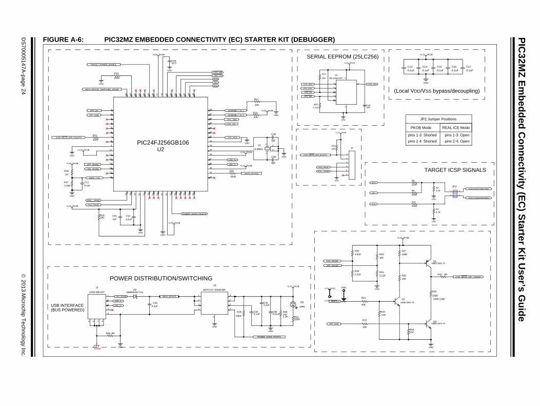
2.1.3 Debug USB Connectivity
The PIC32MZ Embedded Connectivity (EC) Starter Kit includes a PIC24FJ256GB106 USB microcontroller that provides debugger connectivity over USB. The PIC24FJ256GB106 is hard-wired to the PIC32 device to provide protocol translation through the I/O pins of PIC24FJ256GB106 to the ICSP™ pins of the PIC32.
If MPLAB REAL ICE™ or MPLAB ICD 3 are used with the starter kit, it is necessary to disconnect the on-board debugger from the PIC32 device. To do this, remove the JP2 jumper. When the on-board debugger is required, replace the JP2 jumper. When the JP2 jumper is installed, pin 1 must be connected to pin 3 and pin 2 must be connected to pin 4.
2.1.4 PIC32 USB Connectivity
There are three possible ways to connect to the PIC32 USB microcontroller:
• HOST Mode – Connect the device to the Type A connector J4, which is located on the top side of the starter kit. If using the Debug USB port to power the Host port, install jumper JP1 to short the back-power prevention diode. Note that a maximum of ~400 mA can be supplied from the Debug USB port to the Host port using this method. If the full 500 mA supply is needed, an external supply must be con-nected to the application board and jumper JP1 must be removed to prevent back-powering the Debug USB port.
2013 Microchip Technology Inc. DS70005147A-page 15

PIC32MZ Embedded Connectivity (EC) Starter Kit User’s Guide
• DEVICE Mode – Connect the debug mini-B USB cable to port J1 and then connect the starter kit to the host using a cable with a Type-B micro-connector to the starter kit’s micro-A/B port J5, which is located on the bottom side of the board. The other end of the cable must have a Type-A connector. Connect it to a USB host. Jumper JP1 should be removed.
• OTG Mode – Connect the starter kit to the OTG device using an OTG micro-A/B cable to the micro-A/B port J5, which is located on the bottom side of the board. The starter kit provides an on-board power supply capable of providing 120 mA Max. This supply is controlled by the PIC32MZ2048ECH144 microcontroller. Jumper JP1 should be removed.
2.1.5 Switches
Push button switches provide the following functionality:
• SW1: Active-low switch connected to RB12
• SW2: Active-low switch connected to RB13
• SW3: Active-low switch connected to RB14
The switches do not have any debounce circuitry and require the use of internal pull-up resistors; this allows you to investigate software debounce techniques. When Idle, the switches are pulled high (+3.3V). When pressed, they are grounded.
2.1.6 LEDs
The RH0 through RH2 LEDs are connected to PORTH of the processor. The PORTH pins are set high to light the LEDs.
2.1.7 Oscillator Options
The installed microcontroller has an oscillator circuit connected to it. The main oscillator uses an 12 MHz crystal (Y1) and functions as the controller’s primary oscillator. Depending on which is populated on the starter kit board, a 12 MHz external oscillator (Y4) may be used instead of Y1. Use of an external crystal is required to develop USB applications. The USB specification dictates a frequency tolerance of ±0.25% for high speed. Non-USB applications can use the internal oscillators. The starter kit also has provisions for an external secondary 32 kHz oscillator (Y2); however, this is not populated. A suitable oscillator, the ECS-3X8, can be obtained from Digi-Key: Part no. X801-ND CMR200TB32.768KDZFTR.
The PIC24FJ256GB106 is independently clocked and has its own 12 MHz crystal.
2.1.8 168-Pin Modular Expansion Connector
The PIC32MZ Embedded Connectivity (EC) Starter Kit has been designed with a 168-pin modular expansion interface, which allows the board to provide basic generic functionality and easy extendability to new technologies as they become available.
TABLE 2-1: STARTER KIT CONNECTOR PART NUMBERS
Connector HIROSE Electric PN
Starter Kit Connector FX10A-168P-SV1(71)
Application Board Connector FX10A-168S-SV
DS70005147A-page 16 2013 Microchip Technology Inc.

Hardware
2.1.9 Ethernet PHY
The PIC32MZ Embedded Connectivity (EC) Starter Kit has been designed to use a wide variety of Ethernet PHYs through the Reduced Media Independent Interface (RMII). The starter kit comes with a daughter board that is populated with a SMSC 8720A Ethernet PHY. The RMII has been isolated from the expansion connector.
To use a different Ethernet PHY other than what is offered, visit the microchipDIRECT website (www.microchipdirect.com) for the list of alternate options.
2013 Microchip Technology Inc. DS70005147A-page 17

PIC32MZ Embedded Connectivity (EC) Starter Kit User’s Guide
NOTES:
DS70005147A-page 18 2013 Microchip Technology Inc.

PIC32MZ EMBEDDEDCONNECTIVITY (EC)
STARTER KIT USER’S GUIDE
Appendix A. Board Layout and Schematics
A.1 BLOCK DIAGRAM
FIGURE A-1: HIGH-LEVEL BLOCK DIAGRAM OF THE PIC32MZ EMBEDDED CONNECTIVITY (EC) STARTER KIT
PIC32MZ2048ECH144
(PIC24FJ256GB106)
ICSP™
VUSB3V3(1) or+5V_EXT
Debug USB
App
licat
ion
Boa
rd C
onne
ctor
Switches
LEDs
+5V EXT
USB OTG
USB Host
Device/OTG(Type micro-A/B)
Host(Type A)
Note 1: From Debugger USB Port.
+3.3VPowerSupply
EthernetPHY
10/100 Jack
Debugger Circuit
Power Circuit
DaughterBoard
2013 Microchip Technology Inc. DS70005147A-page 19

PIC32MZ Embedded Connectivity (EC) Starter Kit User’s Guide
A.2 BOARD LAYOUT
FIGURE A-2: PIC32MZ EMBEDDED CONNECTIVITY (EC) STARTER KIT LAYOUT (TOP ASSEMBLY)
DS70005147A-page 20 2013 Microchip Technology Inc.

Board Layout and Schematics
FIGURE A-3: PIC32MZ EMBEDDED CONNECTIVITY (EC) STARTER KIT LAYOUT (BOTTOM ASSEMBLY)
2013 Microchip Technology Inc. DS70005147A-page 21

PIC32MZ Embedded Connectivity (EC) Starter Kit User’s Guide
A.3 SCHEMATICSFIGURE A-4: PIC32MZ EMBEDDED CONNECTIVITY (EC) STARTER KIT (PIC32MZ EC FAMILY
DEVICE)
P32_VDD
P32_VDD4.7K
R1
DNP
RG15
TRD1/SQID1/RG12
TRD2/SQID2/RG14
EBID5/PMD5
EBID6/PMD6
EBID7/PMD7
EBID4/PMD4
EBID3/PMD3
EBID2/PMD2
EBID1/PMD1
EBID10/PMD10
EBIA15/PMCS2/RD9
EBIA16/RK0
EBIWE/PMWR/RC3
SOSCO/RC14
EBID15/PMD15
EBID13/PMD13
EBID12/PMD12
EBID9/PMD9
EBID0/PMD0
EBID11/PMD11
EBID8/PMD8
TRD0/SQID0/RG13
TRD3/SQID3/RA7
TRCLK/SQICLK/RA6
SOSCI/RC13
SQICS0/RPD4/RD4
AN14/C1IND/RPG6/SCK2/RG6
AN4/C1INB/RB4
SDA2/RA3
SCL2/RA2
PGEC1/AN1/RPB1/RB1
PGED1/AN0/RPB0/RB0
RPA15/SDA1/RA15
RPA14/SCL1/RA14
INT0/RD0
RPD1/SCK1/RD1
EBIA13/PMA13/RJ13
EBIA12/PMA12/RC2
EBIA11/PMA11/RB12
EBIA10/PMA10/RB8
EBIA9/PMA9
EBIA5/PMA5/RA5
EBIA7/PMA7
EBIA6/PMA6
EBIA3/PMA3
EBIA2/PMA2/RG9
EBIA1/PMA1
EBIA0/PMA0/RJ15
PGED2/AN47/RPB7/RB7
PGEC2/AN46/RPB6/RB6
ICSP_MCLR_VPP_TARGET
TMS/RA0
TCK/RA1
TDO/RF12
TDI/RF13
VREF-/RA9
VREF+/RA10
D+
D-
ETXD0
ETXD1
ERXERR
ERXD1
ERXD0
EBIA19/RK5
EBIA20/RK6
EMDC
EMDIO
ETXEN
EBIA21/RK7
0.01uFC20
0.1uF
C1
P32_VDD0.01uFC21
0.1uFC2
0.1uFC3
P32_VDD0.1uF
C4
P32_VDD0.01uFC24
0.1uFC5
P32_VDD0.01uF
C250.1uFC6
P32_VDD0.01uF
C260.1uFC7
P32_VDD0.01uF
C27
P32_VDD
0.01uFC28
EBIA4/PMA4
VBUS
P32_VDD
P32_VDD
EBID14/PMD14
EREF_CLK
ECRS/RH13
EBIA14/PMCS1/PMA14/RA4
EBIA8/PMA8
EBIA18/RK4
RH0
RH1
RH2
AN7/RB12
AN8/RB13
AN3/C2INA/RPB3/RB3
RF3/USBID/RPF3
AN45/C1INA/RPB5/RB5/VBUSON
SCL3/RPF8/RF8
SQICS1/RPD5/RD5
AN32/AETXD0/RPD14/RD14
AN33/RPD15/SCK6/RD15
AN26/RPE9/RE9
AN25/RPE8/RE8
AN6/RB11
AN13/C1INC/RPG7/SDA4/RG7
AN12/C2IND/RPG8/SCL4/RG8
RPD10/SCK4/RD10
EBICS0/RJ4
EBIA17/RK3
EBIBS0/RJ12
EBIBS1/RJ10
SDA3/RPF2/RF2
AN2/C2INB/RPB2/RB2
AN42/ERXD2/RH6
0.01uFC22
0.01uFC23
0.1uFC8
0.1uFC9
ERXD3/RH9
ECOL/RH10
EBIRDY2/RH11
EBIA23/RH15
EBIADV/RH14
ECRS/RH12
EBICS2/RJ6/SQI_PWR
EBICS1/RJ5
ETXCLK/RPD7/RD7
EBIA22/RJ3
CVREFOUT/AN5/RPB10/RB10
AN10/RPB15/OCFB/RB15
RH3
AN9/RPB14/SCK3/RB14
EBIRDY3/RJ2
ETXERR/RJ0
EBICS3/RJ7
C47DNP
EBIOE/PMRD/RC4
EBIRDY2/RH11 84
ERXD0/RH881
RPF3/USBID/RF3 78
EMDC/AEMDC/RPD11/RD11 99
RPA15/SDA1/RA15 96
EBIA19/RK593
EBIA9/RPF4/SDA5/PMA9/RF4 90
EBIA14/PMCS1/PMA14/RA487
AN25/RPE8/RE823
MCLR20
VSS17
AN14/C1IND/RPG6/SCK2/RG614
EBIA12/AN21/RPC2/PMA12/RC211
AN36/ETXD1/RJ98
EBID7/AN15/PMD7/RE75
EBIA5/AN34/PMA5/RA52
VUSB3V374
AN26/RPE9/RE924
AN45/C1INA/RPB5/RB525
EBIA2/AN11/C2INC/RPG9/PMA2/RG921
VDD18
TMS/AN24/RA022
EBIA16/RK019
AN13/C1INC/RPG7/SDA4/RG715
EBIWE/AN20/RPC3/PMWR/RC312
AN12/C2IND/RPG8/SCL4/RG816
EBIOE/AN19/RPC4/PMRD/RC413
EBIBS0/RJ129
EBIA6/AN22/RPC1/PMA6/RC16
EBIBS1/RJ1010
AN35/ETXD0/RJ87
EBID5/AN17/RPE5/PMD5/RE53
EBID6/AN16/PMD6/RE64
AN23/RG151
ERXD3/RH9 82
SDA3/RPF2/RF2 79
SCL3/RPF8/RF880
VBUS73
VSS 75
D- 76
ECRS/RH12 100
EBIA15/RPD9/PMCS2/PMA15/RD9 97
RPD10/SCK4/RD10 98
EBIA20/RK694
EBIA8/RPF5/SCL5/PMA8/RF5 91
EBIA18/RK4 92
VDD88
SCL2/RA2 85
EBIRDY1/SDA2/RA3 86
ECOL/RH10 83
D+ 77
RPA14/SCL1/RA14 95
VSS 89
AN37/ERXCLK/EREFCLK/RJ1127
EBIA0/PMA0/RJ1530
VDD33
PGED1/AN0/RPB0/RB036
VREF-/CVREF-/AN27/RA939
AVSS42
EBIRP/RH245
EBIA7/AN49/RPB9/PMA7/RB948
AN4/C1INB/RB426
EBIA11/PMA11/RJ1429
EBIA13/PMA13/RJ1328
VSS32
PGEC1/AN1/RPB1/RB135
AN2/C2INB/RPB2/RB234
PGED2/AN47/RPB7/RB738
AVDD41
VREF+/CVREF+/AN28/RA1040
AN39/ETXD3/RH144
EBIA10/AN48/RPB8/PMA10/RB847
EBIWP/RH346
AN6/RB1150
AN3/C2INA/RPB3/RB331
PGEC2/AN46/RPB6/RB637
AN38/ETXD2/RH043
CVREFOUT/AN5/RPB10/RB1049
EBIA17/RK353
TCK/AN29/RA156
AN7/RB1259
AN10/RPB15/OCFB/RB1562
AN40/ERXERR/RH465
EBIA4/PMPA4/RH768
OSCI/CLKI/RC1271
EBIA3/PMA3/RK252
EBIA1/PMA1/RK151
VDD55
TDO/AN31/RPF12/RF1258
VSS54
TDI/AN30/RPF13/SCK5/RF1357
AN9/RPB14/SCK3/RB1461
VDD64
AN8/RB1360
VSS63
AN42/ERXD2/RH667
AN33/RPD15/SCK6/RD1570
AN41/ERXD1/RH566
AN32/AETXD0/RPD14/RD1469
OSCO/CLKO/RC1572
ERXDV/ECRSV/AECRSDV/RH13101
EBIADVN/RH14 102
EBIA23/RH15 103
RPD0/RTCC/INT0/RD0 104
SOSCI/RPC13/RC13 105
SOSCO/RPC14/T1CK/RC14 106
VDD 107
VSS108
RPD1/SCK1/RD1 109
EBID14/RPD2/PMD14/RD2 110
EBID15/RPD3/PMD15/RD3 111
EBID12/RPD12/PMD12/RD12 112
EBID13/PMD13/RD13 113
ETXERR/RJ0114
EMDIO/AEMDIO/RJ1115
EBIRDY3/RJ2 116
EBIA22/RJ3 117
SQICS0/RPD4/RD4 118
SQICS1/RPD5/RD5 119
ETXEN/RPD6/RD6 120
ETXCLK/RPD7/RD7 121
VDD122
VSS 123
EBID11/RPF0/PMD11/RF0 124
EBID10/RPF1/PMD10/RF1 125
EBIA21/RK7 126
EBID9/RPG1/PMD9/RG1 127
EBID8/RPG0/PMD8/RG0128
TRCLK/SQICLK/RA6129
TRD3/SQID3/RA7 130
EBICS0/RJ4 131
EBICS1/RJ5 132
EBICS2/RJ6 133
EBICS3/RJ7 134
EBID0/PMD0/RE0135
VSS136
VDD 137
EBID1/PMD1/RE1 138
TRD2/SQID2/RG14 139
TRD1/SQID1/RG12 140
TRD0/SQID0/RG13 141
EBID2/PMD2/RE2 142
EBID3/RPE3/PMD3/RE3143
EBID4/AN18/PMD4/RE4 144
U1PIC32MZ
33RR48
33RR49
33RR50
33RR51
C49
0RR55
DNP
1
2
3
4
5
6
J7
P32_VDD
PGED2/AN47/RPB7/RB7
PGEC2/AN46/RPB6/RB6
ICSP_MCLR_VPP_TARGET
P32_VDD
P32_VDD
TC25L5I32K7680
EN 1
GND 2OUT3
VDD4
Y2
P32_VDD 0.01uFC36
P32_VDD
0.01uF
C29
P32_VDD
24MHz
EN1
GND2
OUT3
VDD 4Y4
24MHz
Y1
8.0pF
C34
8.0pF
C35
1M±1%
R56
Only Oscillator or Crystal Configuration
should be populated.
Please check PCB/BOM to determine
which configuration is populated
32.768 kHz
DS70005147A-page 22 2013 Microchip Technology Inc.

Board Layout and Schematics
FIGURE A-5: PIC32MZ EMBEDDED CONNECTIVITY (EC) STARTER KIT (USB HOST AND OTG POWER SUPPLIES)
MH1
P32_VDD
ERXD1
ERXD0
ERXERR
EMDIO
EMDC
ETXEN
ETXD0
ETXD1
EREF_CLK
ICSP_MCLR_VPP_TARGET
0.1uF
C19
0RR38
PHY Daughter Board Connections
33RR52
33RR53
R54 DNP
CLK_IN
CLK_IN
EN1
GND2 OUT 3
VDD 4Y5
50MHz
P32_VDD
0.01uFC48
ECRS/RH13
SLM-112-01-G-S + SLM-103-01-G-S
1
2
3
4
5
6
7
8
9
10
11
12
13
14
15
16
17
18
19
20
21
22
23
2425
25
J6
2 HDR/MB
SOSCI/RC13
4.7K
R4
1uF
C33
100KR24
PGOOD 1
Vout 2
Vin 3
GND 4C-5
C+6
SHDN7
SELECT8U5
MCP1253_MSOP
VBUS
P32_VDD
P32_VDD
D+
D-
SH
IELD
6
D-2
5
D+3
VBUS1
4
J4
6
D-2
5
D+3
VBUS1
4
J5
TYPE MICRO A/B
D+
D-C46100uF
+5V_EXT
EN4
IN5
GND 2
OC 3
OUT 1
U6
TPS2051B
* Install Jumper if poweringfrom Debugger Power Supply
USB HOST Power Supply
USB OTG/Device Power Supply (120mA MAX)
+5V_EXT VBUS
D1MBR0520LT1G
DEVICE/OTG PORT
HOST TYPE - TYPE A
+5V_DUSB
10ˇFC44
10ˇFC45
R46
DNP
AN45/C1INA/RPB5/RB5/VBUSON
AN45/C1INA/RPB5/RB5/VBUSON AN2/C2INB/RPB2/RB2
AN2/C2INB/RPB2/RB2
VBUS_DEVICE
RF3/USBID/RPF3
1 2
JP1
D7
GRN
P32_VDD+3.3V_PKOB
330RR13
C424.7uF
FLAGB 4
OUT 5
GND2
ON3
IN1
U7
FPF2104
TARGET_POWER_ENABLE
100KR25
100K
R26
VBUS_DEVICE_SWITCHED_SENSE
R47 DNP
Current Limiting Switch
2013 Microchip Technology Inc. DS70005147A-page 23
PIC
32MZ
Em
bed
ded
Co
nn
ectivity (EC
) Starter K
it User’s G
uid
e
DS
70005147A
-page 24
2013 M
icrochip Technolo
gy Inc.
(Local VDD/VSS bypass/decoupling)
+3.3V_PKOB
C256)
UTIL_SDIGND
TARGET ICSP SIGNALS
SCK
SDI
SDO
GND
GND
ICSP_MCLR_VPP_TARGET
GND
GND
10K
R19
10KR20
0K
22
K
21
4.7KR2
4.7K
R3
330R
R8
330R
R9
330R
R10
2.21K
R31
0.1uF
C14
0.1uF
C15
0.1uF
C16
0.1uF
C17
1uFC32
R42 0R
100K
R27
R44DNP
R43DNP
R36
100R
1206 1/4W
+3.3V_PKOB
MMBT3904-TP
Q2
MMBT3904-TPQ3
MMBT3906-TPQ1
0.1uF
C13
PGEC2/AN46/RPB6/RB6
PGED2/AN47/RPB7/RB7
PKOB Mode REAL ICE Mode
pins 1-3: Shorted pins 1-3: Open
pins 2-4: Shorted pins 2-4: Open
JP2 Jumper Positions
1 3
2 4
JP2
FIGURE A-6: PIC32MZ EMBEDDED CONNECTIVITY (EC) STARTER KIT (DEBUGGER)
+3.3V_PKOB
+3.3V_PKOB
+3.3V_PKOB
+3.3V_PKOB
+3.3V_PKOB
+3.3V_PKOB
+3.3V_PKOB
+3.3V_PKOB
+3.3V_PKOB
SERIAL EEPROM (25L
ASSEMBLY_ID_0
ASSEMBLY_ID_1
ICSP_MCLR_VPP_PICKIT3
ICSP_MCLR_VPP_PICKIT3
POWER_GOOD_PICKIT3
SCK
SDI
SDO
UTIL_CS
UTIL_CS
UTIL_WP
UTIL_WP
USB_D-
USB_D+
UTIL_SCK
UTIL_SCK
UTIL_SDI
UTIL_SDO
UTIL_SDO
VBUS_DEVICE
VDD_SENSE
VPP_GND
VPP_ON
VPP_SENSE
VREF_2.5VGND
+3.3V_PKOB
GND
GND
GND
GND
GNDGND
GND
GND
GND
GND
PGC__PKOB
PGD_PKOB
PGC__PKOB
PGD_PKOB
VDD_SENSE
VPP_GND
VPP_ON
VPP_SENSE
USB_D-
USB_D+
GND
GND
+3.3V_PKOB
POWER_GOOD_PICKIT3
GND
VBUS_DEVICE
POWER DISTRIBUTION/SWITCHING
USB INTERFACE(BUS POWERED)
GND
+3.3V_PKOB
EGND
10K
R14
10K
R15
10KR16
1
R
10
R
10K
R18
R39 0R
330R
R11
330RR12
2.21K
R32
2.21K
R30
2.2uFC40
2.2uFC41
0.1uFC11
0.1uF
C12
0.01uFC30
0.1uFC10
C38
8pF
C39
8pF
10ˇFC43
200K
R29
200K
R28
100R
R35
1uF
C31
R33
3.92K
R37
3.16K
R45DNP2.2K
1K
R34
4
13
2Y3
12.0MHz
D6
GRN
SCK6
SI5
CS1
WP3
VS
S4
SO2
VC
C8
HOLD7
U4
25LC256-I/ST
D2MBR0520LT1G
D+ 3
D- 2
GND 5
ID4
6789
VUSB1
, , ,
J3
UX60-MB-5ST
1
2
3
4
5
6
J2
AN
6/R
B6
17P
MP
D4/
RE
464
AV
SS
20P
MP
D1/
RE
161
PM
A13
/AN
10/R
B10
23R
F0
58
VD
D26
RD
755
PM
A1/
AN
14/R
B14
29P
MW
R/R
D4
52
PM
A8/
SC
L2/R
F5
32V
CP
CO
N/R
D1
49
AN0/RB016
AN3/RB313
VDD10
MCLR7
PMA5/RG64
PMD5/RE51
USBID/RF333
D-/RG336
OSC1/CLKIN/RC1239
RTCC/RD8 42
PMCS1/RD11 45
SOSCO/RC14 48
AN2/RB214
AN1/RB115
PMA2/RG98
VSS9
AN5/RB511
PMD6/SCL3/RE62
PMD7/SDA3/RE73
PMA4/RG75
AN
7/R
B7
18
AV
DD
19
AN
8/R
B8
21
PM
PD
3/R
E3
63
PM
PD
2/R
E2
62
PM
PD
0/R
E0
60
PM
A12
/AN
11/R
B11
24
VS
S25
PM
A11
/AN
12/R
B12
27
EN
VR
EG
57
Vca
p/V
DD
CO
RE
56
RD
654
PM
A0/
AN
15/R
B15
30
PM
A9/
SD
A2/
RF
431
PM
BE
/RD
351
DH
P/R
D2
50
Vusb35
Vbus34
VSS41
OSC2/CLKO/RC1540
VDD38
SOSCI/RC13 47
INT0/RD0 46
SCL1/PMCS2/RD10 44
USBOENAN4/RB412
PMA3/RG86
D+/RG237
SDA1/RD9 43
PM
A7/
AN
9/R
B9
22R
F1
59
PM
A10
/AN
13/R
B13
28P
MR
D/R
D5
53
U2PIC24FJ256GB106
GN
D_E
P9
GND4
VIN1
PWRGD5
VOUT8
VIN2
SHDN3
SENSE 7
CDELAY 6
U3
MCP1727-3302E/MF
+3.3V_PKOB
GND
10K
R17
+5V_DUSB
VBUS_DEVICE_SWITCHED_SENSE
TARGET_POWER_ENABLE

Board Layout and Schematics
FIGURE A-7: PIC32MZ EMBEDDED CONNECTIVITY (EC) STARTER KIT (APPLICATION BOARD CONNECTOR, SQI MEMORY AND POWER, LEDS, AND SWITCHES)
117 118
111 112
105 106
99 100
93 94
87 88
81 82
75 76
69 70
57 58
51 52
45 46
39 40
33 34
27 28
21 22
15 16
9 10
3 4
119 120
107 108
109 110
113 114
115 116
95 96
97 98
101 102
103 104
83 84
85 86
89 90
91 92
71 72
73 74
77 78
79 80
59 60
61 62
65 66
67 68
47 48
49 50
53 54
55 56
35 36
37 38
41 42
43 44
25 26
29 30
23 24
19 20
13 14
17 18
11 12
7 8
1 2
5 6
31 32
63 64
121 122
123 124
125 126
127 128
129 130
135 136
137 138
131 132
133 134
139 140
141 142
143 144
145
148
149 150
151 152
153 154
159 160
161 162
155 156
157 158
163 164
165 166
167 168
146
147
J1
FX
10A
-168P
-SV
1(7
1)
RG15
P32_VDD
TRD2/SQID2/RG14
EBID5/PMD5
EBID4/PMD4
EBID3/PMD3
EBID2/PMD2
EBID1/PMD1
INT0/RD0
EBIA6/PMA6
EBIA4/PMA4
EBIA3/PMA3
EBIA2/PMA2/RG9
EBIA1/PMA1
EBIA0/PMA0/RJ15
AN4/C1INB/RB4
EBIA5/PMA5/RA5
AN3/C2INA/RPB3/RB3
AN45/C1INA/RPB5/RB5/VBUSON
AN33/RPD15/SCK6/RD15
AN25/RPE8/RE8
EBIA17/RK3
EBIA18/RK4
AN26/RPE9/RE9
EBIA19/RK5
EBIA20/RK6
EBIA21/RK7
EBIA23/RH15
EBIADV/RH14
EBICS1/RJ5
PGEC1/AN1/RPB1/RB1
AN2/C2INB/RPB2/RB2
AN14/C1IND/RPG6/SCK2/RG6
RPD10/SCK4/RD10
+5V_EXT
ICSP_MCLR_VPP_TARGET
TMS/RA0
TCK/RA1TDO/RF12
TDI/RF13
VREF-/RA9
VREF+/RA10
SDA2/RA3
SCL2/RA2
EBIWE/PMWR/RC3
EBID15/PMD15
EBID14/PMD14
EBID13/PMD13
EBID12/PMD12
EBID9/PMD9
EBID10/PMD10
EBID11/PMD11
TRD0/SQID0/RG13
TRD1/SQID1/RG12
TRCLK/SQICLK/RA6
SOSCO/RC14
SOSCI/RC13
SQICS1/RPD5/RD5
EBIA16/RK0
AN42/ERXD2/RH6
AN6/RB11
RH0
RH1
ERXD3/RH9
ECOL/RH10
EBIRDY2/RH11
ETXCLK/RPD7/RD7
CVREFOUT/AN5/RPB10/RB10
SQICS0/RPD4/RD4
RPD1/SCK1/RD1
SCL3/RPF8/RF8
SDA3/RPF2/RF2
AN10/RPB15/OCFB/RB15
EBIRDY3/RJ2
RH3
PGED1/AN0/RPB0/RB0
AN7/RB12
AN9/RPB14/SCK3/RB14
P32_VDDP32_VDD
P32_VDD
+5V_EXT
P32_VDD
P32_VDD P32_VDD
P32_VDD
+5V_EXT +5V_EXT
EBID15/PMD15
EBID4/PMD4
EBIA14/PMCS1/PMA14/RA4
EBIA15/PMCS2/RD9
EBIA13/PMA13/RJ13
EBIA12/PMA12/RC2
EBIA11/PMA11/RB12
EBIA10/PMA10/RB8
EBIA9/PMA9
EBIA8/PMA8
EBIA7/PMA7
AN8/RB13
ETXERR/RJ0
EBIBS0/RJ12
EBIBS1/RJ10
EBIA22/RJ3
EBICS0/RJ4
DEBUG
MCLR
SOSC
EB
I AD
DR
ES
S
INTO
JTAG
EB
I A
DD
RE
SS
EB
I A
DD
RE
SS
EB
I CO
NT
DEBUG
JTAG
TR
AC
EE
BI D
AT
AE
BI C
ON
TR
OL
EB
I DA
TA
EB
I CO
NT
RO
LCE# 1
SO/SIO12
SIO23
VSS4
SI/SIO05
SCK 6
SIO37
VDD8
U9
SST26VF032
0.1uFC18
SQI_VDD
SQICS1/RPD5/RD5
TRCLK/SQICLK/RA6TRD2/SQID2/RG14
TRD3/SQID3/RA7
TRD0/SQID0/RG13
TRD1/SQID1/RG12
330R
R5
330R
R7
330R
R6
GreenD5
LED2
RedD3
LED1
YellowD4
LED3
USER LEDS'
S1
S2
S3
GND
USERSSWITCH'
RH0
RH1
RH2
AN7/RB12
AN8/RB13
AN9/RPB14/SCK3/RB14
10KR23
SQI_VDD
P32_VDD
EBICS2/RJ6/SQI_PWR
EBICS3/RJ7
EBICS2/RJ6/SQI_PWR
EBID0/PMD0
EBID6/PMD6
RH2
EBIOE/PMRD/RC4
RPA15/SDA1/RA15
RPA14/SCL1/RA14
RF3/USBID/RPF3
PGEC2/AN46/RPB6/RB6
PGED2/AN47/RPB7/RB7
AN13/C1INC/RPG7/SDA4/RG7
AN12/C2IND/RPG8/SCL4/RG8
GP
IOLC
DR
GB
GP
IO/P
PS
AD
C
GP
IOLC
DR
GB
GP
IO/P
PS
I2C
EBID15/PMD15
EBID15/PMD15
EBID7/PMD7
EBID8/PMD8
EBID10/PMD10
EBID10/PMD10
EBID4/PMD4
EBID4/PMD4
TRD3/SQID3/RA7
AN45/C1INA/RPB5/RB5/VBUSON
AN32/AETXD0/RPD14/RD14
G
S
D
Q5
ECRS/RH12
AN9/RPB14/SCK3/RB14
AN12/C2IND/RPG8/SCL4/RG8
AN14/C1IND/RPG6/SCK2/RG6 ETXCLK/RPD7/RD7
2013 Microchip Technology Inc. DS70005147A-page 25

PIC32MZ Embedded Connectivity (EC) Starter Kit User’s Guide
NOTES:
DS70005147A-page 26 2013 Microchip Technology Inc.
PIC32MZ EMBEDDEDCONNECTIVITY (EC)
STARTER KIT USER’S GUIDE
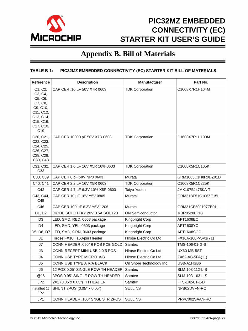
Appendix B. Bill of Materials
TABLE B-1: PIC32MZ EMBEDDED CONNECTIVITY (EC) STARTER KIT BILL OF MATERIALS
Reference Description Manufacturer Part No.
C1, C2, C3, C4, C5, C6, C7, C8,
C9, C10, C11, C12, C13, C14, C15, C16, C17, C18,
C19
CAP CER .10 µF 50V X7R 0603 TDK Corporation C1608X7R1H104M
C20, C21, C22, C23, C24, C25, C26, C27, C28, C29, C30, C48
CAP CER 10000 pF 50V X7R 0603 TDK Corporation C1608X7R1H103M
C31, C32, C33
CAP CER 1.0 µF 16V X5R 10% 0603 TDK Corporation C1608X5R1C105K
C38, C39 CAP CER 8 pF 50V NP0 0603 Murata GRM1885C1H8R0DZ01D
C40, C41 CAP CER 2.2 µF 16V X5R 0603 TDK Corporation C1608X5R1C225K
C42 CAP CER 4.7 µF 6.3V 10% X5R 0603 Taiyo Yuden JMK107BJ475KA-T
C43, C44, C45
CAP CER 10 µF 16V Y5V 0805 Murata GRM21BF51C106ZE15L
C46 CAP CER 100 µF 6.3V Y5V 1206 Murata GRM31CF50J107ZE01L
D1, D2 DIODE SCHOTTKY 20V 0.5A SOD123 ON Semiconductor MBR0520LT1G
D3 LED, SMD, RED, 0603 package Kingbright Corp APT1608EC
D4 LED, SMD, YEL, 0603 package Kingbright Corp APT1608YC
D5, D6, D7 LED, SMD, GRN, 0603 package Kingbright Corp APT1608SGC
J1 Hirose FX10_ 168-pin Header Hirose Electric Co Ltd FX10A-168P-SV1(71)
J7 CONN HEADER .050" 6 POS PCB GOLD Samtec TMS-106-01-G-S
J3 CONN RECEPT MINI USB 2.0 5 POS Hirose Electric Co Ltd UX60-MB-5ST
J4 CONN USB TYPE MICRO_A/B Hirose Electric Co Ltd ZX62-AB-5PA(11)
J5 CONN USB TYPE A R/A BLACK On Shore Technology Inc USB-A1HSB6
J6 12 POS 0.05" SINGLE ROW TH HEADER Samtec SLM-103-112-L-S
@J6 3POS 0.05" SINGLE ROW TH HEADER Samtec SLM-103-103-L-S
JP2 2X2 (0.05"x 0.05") TH HEADER Samtec FTS-102-01-L-D
installed @ JP2
SHUNT 2POS (0.05" x 0.05") SULLINS NPB02DVFN-RC
JP1 CONN HEADER .100" SNGL STR 2POS SULLINS PRPC002SAAN-RC
2013 Microchip Technology Inc. DS70005147A-page 27

PIC32MZ Embedded Connectivity (EC) Starter Kit User’s Guide
Q1 TRANS SS PNP 40V 300MW SOT23 Micro Commercial Co. MMBT3906-TP
Q2, Q3 TRANSISTOR NPN GP 40V SOT23 Micro Commercial Co. MMBT3904-TP
Q5 MOSFET P-CH 8V 3.7A SOT23-3 ON Semiconductor NTR2101PT1G
R1, R2, R3, R4
RES 4.7K OHM 1/10W 1% 0603 SMD Stackpole Electronics Inc. RMCF0603FT4K70
R5, R6, R7, R8,
R9, R10, R11, R12,
R13
RES 330 OHM 1/10W 1% 0603 SMD Stackpole Electronics Inc. RMCF0603FT330R
R14, R15, R16, R17, R18, R19, R20, R21, R22, R23
RES 10K OHM 1/10W 1% 0603 SMD Stackpole Electronics Inc. RMCF0603FT10K0
R24, R25, R26, R27
RES 100K OHM 1/10W 1% 0603 SMD Stackpole Electronics Inc. RMCF0603FT100K
R28, R29 RES 200K OHM 1/10W 1% 0603 SMD Stackpole Electronics Inc. RMCF0603FT200K
R30, R31, R32
RES 2.21K OHM 1/10W 1% 0603 SMD Panasonic - ECG ERJ-3EKF2211V
R33 RES 3.92K OHM 1/10W 1% 0603 SMD Yageo RC0603FR-073K92L
R34 RES 1K OHM 1/10W 1% 0603 SMD Stackpole Electronics Inc. RMCF0603FT1K00
R35 RES 100 OHM 1/10W 5% 0603 SMD Yageo RC0603JR-07100RL
R36 RES 100 OHM 1/4W 1% 1206 SMD Yageo RC1206FR-07100RL
R37 RES 3.16K OHM 1/10W 1% 0603 SMD Yageo RC0603FR-073K16L
R38, R39, R42, R55
RES 0.0 OHM 1/10W 0603 SMD Rohm Semiconductor MCR03EZPJ000
R48, R49, R50, R51, R52, R53
RES 33 OHM 1/10W 1% 0603 SMD Stackpole Electronics Inc. RMCF0603FT33R0
S1, S2, S3 Switch, Tact, PB MOM SMT, Series TL3302
C&K PTS635SK25SMTR LFS
U1 PIC32MZ2048ECH144-I/PH Microchip Technology Inc. PIC32MZ2048ECH144-I/PH
U2 IC PIC MCU FLASH 256K 64-TQFP Microchip Technology Inc. PIC24FJ256GB106-I/PT
U3 IC REG LDO 1.5A 3.3V 8DFN Microchip Technology Inc. MCP1727-3302E/MF
U4 IC EEPROM 256 KBIT 10 MHz 8TSSOP Microchip Technology Inc. 25LC256-I/ST
U5 IC MULT CONFIG 3.3/5V .12A 8MSOP Microchip Technology Inc. MCP1253-33X50I/MS
U6 IC PWR DIST SWITCH SNGL SOT23-5 Texas Instruments TPS2051BDBVR
U7 IC SWITCH LOAD FULL FUNC SOT23-5 Fairchild Semiconductor FPF2104
U9 IC FLASH 32 MBIT 8-pin SOIC Microchip Technology Inc. SST26VF032-80-5I-S2AE
Y3 CRYSTAL 12.000000 MHZ 8 pF SMD NDK NX3225SA-12.000000MHZ
Y4 OSC MEMS 24.000 MHz SMD Abracon Corporation ASDMB-24.000MHZ-LC-T
Y5 OSC MEMS 50.000 MHz_1.8V ~3.3V SMD
Abracon Corporation ASEMB-50.000MHZ-LC-T
+3.3V_P-KOB, GND
PC TEST POINT MINIATURE SMT Keystone Electronics 5015
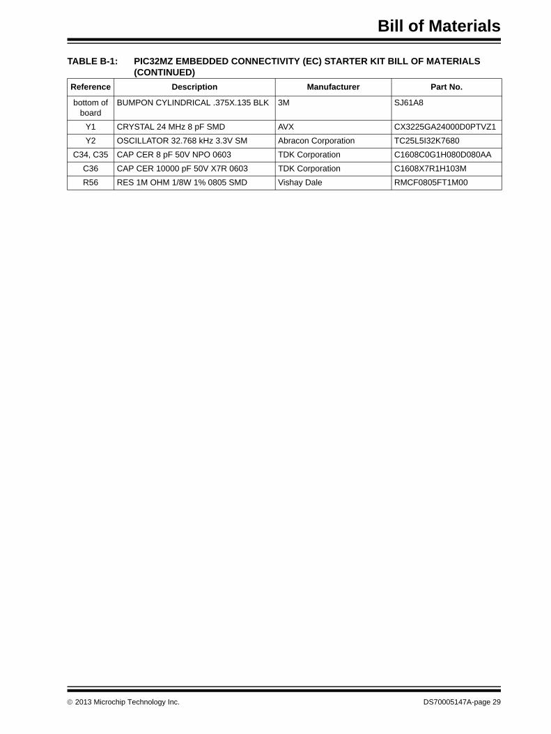
TABLE B-1: PIC32MZ EMBEDDED CONNECTIVITY (EC) STARTER KIT BILL OF MATERIALS (CONTINUED)
Reference Description Manufacturer Part No.
DS70005147A-page 28 2013 Microchip Technology Inc.
Bill of Materials
bottom of board
BUMPON CYLINDRICAL .375X.135 BLK 3M SJ61A8
Y1 CRYSTAL 24 MHz 8 pF SMD AVX CX3225GA24000D0PTVZ1
Y2 OSCILLATOR 32.768 kHz 3.3V SM Abracon Corporation TC25L5I32K7680
C34, C35 CAP CER 8 pF 50V NPO 0603 TDK Corporation C1608C0G1H080D080AA
C36 CAP CER 10000 pF 50V X7R 0603 TDK Corporation C1608X7R1H103M
R56 RES 1M OHM 1/8W 1% 0805 SMD Vishay Dale RMCF0805FT1M00
TABLE B-1: PIC32MZ EMBEDDED CONNECTIVITY (EC) STARTER KIT BILL OF MATERIALS (CONTINUED)
Reference Description Manufacturer Part No.
2013 Microchip Technology Inc. DS70005147A-page 29

PIC32MZ Embedded Connectivity (EC) Starter Kit User’s Guide
NOTES:
DS70005147A-page 30 2013 Microchip Technology Inc.

2013 Microchip Technology Inc. DS70005147A-page 31
NOTES:

DS70005147A-page 32 2013 Microchip Technology Inc.
AMERICASCorporate Office2355 West Chandler Blvd.Chandler, AZ 85224-6199Tel: 480-792-7200 Fax: 480-792-7277Technical Support: http://www.microchip.com/supportWeb Address: www.microchip.com
AtlantaDuluth, GA Tel: 678-957-9614 Fax: 678-957-1455
Austin, TXTel: 512-257-3370
BostonWestborough, MA Tel: 774-760-0087 Fax: 774-760-0088
ChicagoItasca, IL Tel: 630-285-0071 Fax: 630-285-0075
ClevelandIndependence, OH Tel: 216-447-0464 Fax: 216-447-0643
DallasAddison, TX Tel: 972-818-7423 Fax: 972-818-2924
DetroitNovi, MI Tel: 248-848-4000
Houston, TX Tel: 281-894-5983
IndianapolisNoblesville, IN Tel: 317-773-8323Fax: 317-773-5453
Los AngelesMission Viejo, CA Tel: 949-462-9523 Fax: 949-462-9608
New York, NY Tel: 631-435-6000
San Jose, CA Tel: 408-735-9110
Canada - TorontoTel: 905-673-0699 Fax: 905-673-6509
ASIA/PACIFICAsia Pacific OfficeSuites 3707-14, 37th FloorTower 6, The GatewayHarbour City, KowloonHong KongTel: 852-2401-1200Fax: 852-2401-3431
Australia - SydneyTel: 61-2-9868-6733Fax: 61-2-9868-6755
China - BeijingTel: 86-10-8569-7000 Fax: 86-10-8528-2104
China - ChengduTel: 86-28-8665-5511Fax: 86-28-8665-7889
China - ChongqingTel: 86-23-8980-9588Fax: 86-23-8980-9500
China - HangzhouTel: 86-571-2819-3187 Fax: 86-571-2819-3189
China - Hong Kong SARTel: 852-2943-5100 Fax: 852-2401-3431
China - NanjingTel: 86-25-8473-2460Fax: 86-25-8473-2470
China - QingdaoTel: 86-532-8502-7355Fax: 86-532-8502-7205
China - ShanghaiTel: 86-21-5407-5533 Fax: 86-21-5407-5066
China - ShenyangTel: 86-24-2334-2829Fax: 86-24-2334-2393
China - ShenzhenTel: 86-755-8864-2200 Fax: 86-755-8203-1760
China - WuhanTel: 86-27-5980-5300Fax: 86-27-5980-5118
China - XianTel: 86-29-8833-7252Fax: 86-29-8833-7256
China - XiamenTel: 86-592-2388138 Fax: 86-592-2388130
China - ZhuhaiTel: 86-756-3210040 Fax: 86-756-3210049
ASIA/PACIFICIndia - BangaloreTel: 91-80-3090-4444 Fax: 91-80-3090-4123
India - New DelhiTel: 91-11-4160-8631Fax: 91-11-4160-8632
India - PuneTel: 91-20-3019-1500
Japan - OsakaTel: 81-6-6152-7160 Fax: 81-6-6152-9310
Japan - TokyoTel: 81-3-6880- 3770 Fax: 81-3-6880-3771
Korea - DaeguTel: 82-53-744-4301Fax: 82-53-744-4302
Korea - SeoulTel: 82-2-554-7200Fax: 82-2-558-5932 or 82-2-558-5934
Malaysia - Kuala LumpurTel: 60-3-6201-9857Fax: 60-3-6201-9859
Malaysia - PenangTel: 60-4-227-8870Fax: 60-4-227-4068
Philippines - ManilaTel: 63-2-634-9065Fax: 63-2-634-9069
SingaporeTel: 65-6334-8870Fax: 65-6334-8850
Taiwan - Hsin ChuTel: 886-3-5778-366Fax: 886-3-5770-955
Taiwan - KaohsiungTel: 886-7-213-7830
Taiwan - TaipeiTel: 886-2-2508-8600 Fax: 886-2-2508-0102
Thailand - BangkokTel: 66-2-694-1351Fax: 66-2-694-1350
EUROPEAustria - WelsTel: 43-7242-2244-39Fax: 43-7242-2244-393Denmark - CopenhagenTel: 45-4450-2828 Fax: 45-4485-2829
France - ParisTel: 33-1-69-53-63-20 Fax: 33-1-69-30-90-79
Germany - DusseldorfTel: 49-2129-3766400
Germany - MunichTel: 49-89-627-144-0 Fax: 49-89-627-144-44
Germany - PforzheimTel: 49-7231-424750
Italy - Milan Tel: 39-0331-742611 Fax: 39-0331-466781
Italy - VeniceTel: 39-049-7625286
Netherlands - DrunenTel: 31-416-690399 Fax: 31-416-690340
Poland - WarsawTel: 48-22-3325737
Spain - MadridTel: 34-91-708-08-90Fax: 34-91-708-08-91
Sweden - StockholmTel: 46-8-5090-4654
UK - WokinghamTel: 44-118-921-5800Fax: 44-118-921-5820
Worldwide Sales and Service
10/28/13