Embed Size (px)
Citation preview
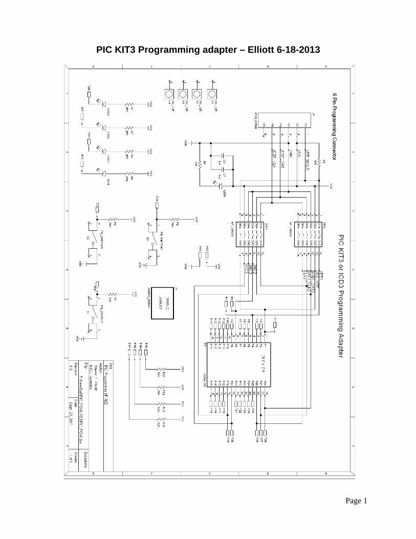
PIC KIT3 Programming adapter – Elliott 6-18-2013
Page 1
PIC KIT3 Programming adapter – Elliott 6-18-2013
Page 2
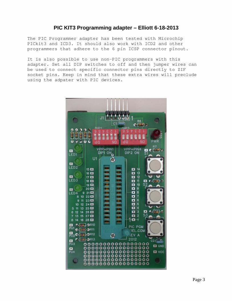
Bill of Materials: Reference Designator QTY Description ----------------------------------------------------------- C1,C2 2 .1uF ceramic capacitor R10,R11,R12,R13,R5,R7,R8, R9 8 10K 1/8W resisitor U1 1 28PIN_ZIF R1,R2,R3,R4,R6 5 470 DIP1,DIP2 2 6 position DIP Switch J1 1 Programmer Connector LED1,LED2,LED3,LED4,LED5 5 LED S1,S2,S3 3 Pushbutton Switch Assembly is fairly easy, install resistors and capacitors first using the bill of materials and photograph on page 3 as guides. Install DIP switch and ZIF socket next. Make sure ZIF socket handle location matches silkscreen. When installing LEDs, make sure you match the flat side of the LED with the silkscreen, this is the cathode side. The anode side is the long lead and it goes in the hole opposite the flat side pin. The PIC programmer will work with almost all PIC controllers that employ VPP on Pin 1 or Pin 4. If VPP is on pin 1, set all switches on DIP1 to on and all switches on DIP2 to off. Conversely, If VPP is on pin 4, set all switches on DIP1 to off and all switches on DIP2 to on. PIC PIN 1 is on the lower right as shown in the picture. The PWR LED is lit when power has been applied to the board from PIK-KIT3 or ICD3. You will need to configure the programmer to power the target: Programmer->Settings->Power->Power target circuit from PICkit3. I recommend using a 3.3V supply. There are debug/test facilities included on the board. Three pushbutton switches with on board pull ups can be jumpered over to PIC socket pins. Additionally, four LEDs with series resistors are also included. A custom curcuit area is also provided for implementing special test circuitry. One advantage of powering the target from the programmer is that no external supply is needed and PICs can be tested directly after programming.
PIC KIT3 Programming adapter – Elliott 6-18-2013
Page 3
The PIC Programmer adapter has been tested with Microchip PICkit3 and ICD3. It should also work with ICD2 and other programmers that adhere to the 6 pin ICSP connector pinout. It is also possible to use non-PIC programmers with this adapter. Set all DIP switches to off and then jumper wires can be used to connect specific connector pins directly to ZIF socket pins. Keep in mind that these extra wires will preclude using the adpater with PIC devices.