Embed Size (px)
DESCRIPTION
sphere
Citation preview

PHYSICAL REVIEW E 85, 051305 (2012)
Dense packings of spheres in cylinders: Simulations
A. MughalInstitute of Mathematics and Physics, Aberystwyth University, Penglais, Aberystwyth, Ceredigion, Wales, SY23 3BZ, United Kingdom
H. K. Chan, D. Weaire, and S. HutzlerFoams and Complex Systems, School of Physics, Trinity College Dublin, Dublin 2, Ireland
(Received 15 March 2012; published 11 May 2012)
We study the optimal packing of hard spheres in an infinitely long cylinder, using simulated annealing, andcompare our results with the analogous problem of packing disks on the unrolled surface of a cylinder. The denseststructures are described and tabulated in detail up to D/d = 2.873 (ratio of cylinder and sphere diameters). Thisextends previous computations into the range of structures which include internal spheres that are not in contactwith the cylinder.
DOI: 10.1103/PhysRevE.85.051305 PACS number(s): 45.70.−n, 64.75.Yz, 81.16.Rf, 87.18.Hf
I. INTRODUCTION
The dense packing of monodisperse (equal-sized) hardspheres in a cylinder has been found to produce a remarkablesequence of interesting structures as the ratio of the cylinderdiameter to the sphere diameter is varied. We have exploredcomputationally the densest of these packings in detail usingsimulated annealing, following the work of Pickett et al. [1],and the first four packings in this sequence are shown in Fig. 1.We have reported extensive results, together with analyticapproximations which serve to elucidate our findings [2].The present paper and its future continuations amplify theprevious reports by Mughal et al. [2] and by Chan (secondauthor of the present paper) [3], and extend them in variousdirections. In particular, new results are provided for largercylinder diameters and we include full details of all structuresin a form suitable for future reference.
We shall refer to these quasi-one-dimensional (quasi-1D)packings as columnar crystals since they are periodic; eachstructure can be assembled by stacking unit cells ad infinitumalong the length of the cylinder with each subsequent unit cellrotated by the same twist angle with respect to the previous one.
For smaller cylinder diameters, up to and beyond the rangeinvestigated by Pickett et al. [1], the densest packings onlyconsist of spheres that are in contact with the surface ofthe cylinder. Eventually at larger cylinder diameters densepackings are found for which there are internal spheres thatare not in contact with the surface. Nevertheless we extendthe study of structures with only cylinder-touching spheres tolarger diameters, for its own sake. As already explained inRef. [2], these structures are readily understood by recourse toa yet simpler problem, in which circular disks are placed on acylinder. This can be fully worked out in analytical terms.
In parallel with our computational study using simulatedannealing and a separate investigation by Chan [3] usingsequential deposition, a number of experiments have beenundertaken on the packing of solid spheres and small bubblesunder gravity. Many of the simulated structures are observed.While we will have cause to mention these experiments, theirpresentation will be reserved for a later paper [4].
Some of the structures that we describe (particularly themore elementary ones) have been observed in biologicalmicrostructures [5]. Columnar crystals have also been realized
in numerous experimental contexts including foams (bothdry [6–10] and wet [4]) in tubes, colloids in microchannels[11–15], and fullerenes in nanotubes [16–18]).
We have not attempted to rigorously prove that the densestpackings identified by simulations are indeed the densestpossible. This ought to be achievable for some of the simplestones.
II. MOTIVATION AND BACKGROUND
The identification of dense packings has always playedan important part in condensed matter physics and physicalchemistry [19]. The entities which are to be packed are oftenspherical, or well approximated as such, and they may bemonodisperse. In the idealized case of hard spheres (with nointeraction when not in contact) the problem of finding themaximum density with given boundary conditions constitutesa classic mathematical challenge. If posed for an unboundedpacking, it is long associated with the name of Kepler [20].
Here we are concerned with the case in which spheresof diameter d are to be contained in an unbounded cylinderof diameter D. We shall pursue it up to D/d = 2.873which represents the limit of the capability of our presentcomputational resources and methods.
Our primary objective is to identify the structure with thelargest value of �, defined as the fraction of volume occupiedby the spheres.
There are close connections between this topic and that ofphyllotaxis, a subject arising out of biology and having to dowith the dense arrangement of similar units on the surfaceof a cylinder, exemplified by pine cones, pineapples, or corncobs [21]. This connection will be explored in detail here.
III. SOME SIMPLE COLUMNAR CRYSTALS
For certain specific values of D/d the optimal packingstructure can be easily surmised. These structures are directlyrelated to the analogous two-dimensional problem of findingthe smallest diameter circle into which N nonoverlappingcircles, each of diameter d, can be packed. A description ofthese special cases will serve to illustrate the general problemthat we will address.
051305-11539-3755/2012/85(5)/051305(17) ©2012 American Physical Society

A. MUGHAL, H. K. CHAN, D. WEAIRE, AND S. HUTZLER PHYSICAL REVIEW E 85, 051305 (2012)
FIG. 1. (Color online) The first four densest sphere packings in acylinder.
The first five of these special solutions, labeled CN , areshown schematically in Fig. 2 and (for N > 2) consist of disksplaced at the vertices of a regular polygon. The diameter ofthe enclosing circle is given by
Dc(N ) ={
d if N = 1,
d(1 + 1
sin(π/N)
)if N � 2,
(1)
where Dc(2) = 2d, Dc(3) = 2.1547d, Dc(4) = 2.4142d,Dc(5) = 2.7013d.
Replacing the circles with N spheres we define a unit cellwhich can be repeated along the length of the tube as follows.Each successive layer, indicated by alternating yellow (lightgray) and blue (dark gray), can be generated by translating theprevious layer through a distance,
Lc(N ) ={
d if N = 1,
d2
√3 − (1−cos(π/N))
(1+cos(π/N)) if N � 2,(2)
along the tube and rotating it by a twist angle αc(N ) = π/N .Using the above formula the volume fraction � of thesesimple columnar crystals can easily be computed, �(1) =2/3, �(2) = 0.4714, �(3) = 0.5276, �(4) = 0.5441, �(5) =0.5370.
We shall label these simple columnar crystals with thenotation CN to indicate that their structure can be derivedin a simple way from the circle packing problem.
IV. SIMULATION
For general values of D/d, the optimal packing structurecannot be guessed easily and we must turn to heuristicmethods. Our search method is confined to structures that areperiodic in the following sense. There is a primitive cell, oflength L, containing N spheres, the structure being generated
FIG. 2. (Color online) (Top) The first five solutions of the circlepacking problem. (Bottom) Five columnar structures correspondingto the first five solutions of the circle packing problem. The unit cellsare shown in yellow (light gray) and blue (dark gray).
from this by the screw operation of (i) translation alongthe cylinder axis by nL (where n is any integer) combinedwith (ii) rotation about the axis by an angle nα. This screwoperation represents the underlying symmetry of columnarcrystals (which are not to be confused with columnar phases,originating in the study of liquid crystals and related insteadto the packing of columns).
Our primary method of simulation is based on the well-known approach of simulated annealing. This provides areasonably exhaustive and unbiased search for maximumdensity. Appendix A summarizes the technical details of thepresent application (such as annealing schedules). The searchprocedure described in Appendix A looks for the minimumpossible value of L, for a given N , treating α and the sphere
051305-2
DENSE PACKINGS OF SPHERES IN CYLINDERS: . . . PHYSICAL REVIEW E 85, 051305 (2012)
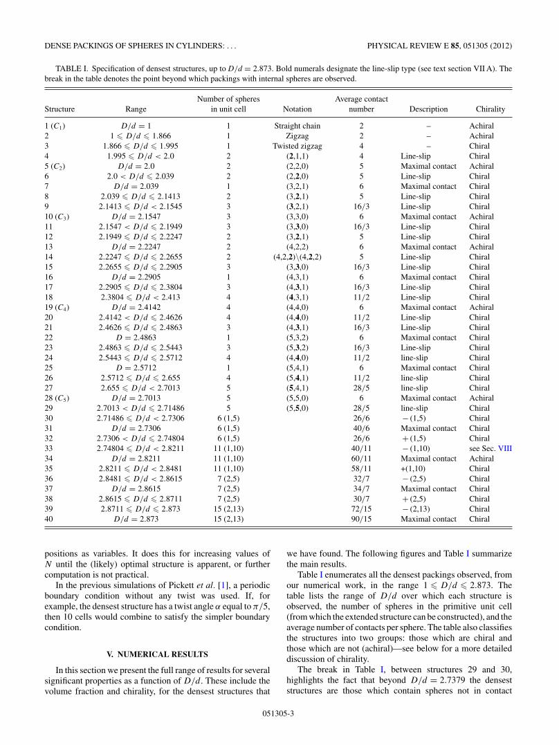
TABLE I. Specification of densest structures, up to D/d = 2.873. Bold numerals designate the line-slip type (see text section VII A). Thebreak in the table denotes the point beyond which packings with internal spheres are observed.
Number of spheres Average contactStructure Range in unit cell Notation number Description Chirality
1 (C1) D/d = 1 1 Straight chain 2 – Achiral2 1 � D/d � 1.866 1 Zigzag 2 – Achiral3 1.866 � D/d � 1.995 1 Twisted zigzag 4 – Chiral4 1.995 � D/d < 2.0 2 (2,1,1) 4 Line-slip Chiral5 (C2) D/d = 2.0 2 (2,2,0) 5 Maximal contact Achiral6 2.0 < D/d � 2.039 2 (2,2,0) 5 Line-slip Chiral7 D/d = 2.039 1 (3,2,1) 6 Maximal contact Chiral8 2.039 � D/d � 2.1413 2 (3,2,1) 5 Line-slip Chiral9 2.1413 � D/d < 2.1545 3 (3,2,1) 16/3 Line-slip Chiral10 (C3) D/d = 2.1547 3 (3,3,0) 6 Maximal contact Achiral11 2.1547 < D/d � 2.1949 3 (3,3,0) 16/3 Line-slip Chiral12 2.1949 � D/d � 2.2247 2 (3,2,1) 5 Line-slip Chiral13 D/d = 2.2247 2 (4,2,2) 6 Maximal contact Achiral14 2.2247 � D/d � 2.2655 2 (4,2,2)\(4,2,2) 5 Line-slip Chiral15 2.2655 � D/d � 2.2905 3 (3,3,0) 16/3 Line-slip Chiral16 D/d = 2.2905 1 (4,3,1) 6 Maximal contact Chiral17 2.2905 � D/d � 2.3804 3 (4,3,1) 16/3 Line-slip Chiral18 2.3804 � D/d < 2.413 4 (4,3,1) 11/2 Line-slip Chiral19 (C4) D/d = 2.4142 4 (4,4,0) 6 Maximal contact Achiral20 2.4142 < D/d � 2.4626 4 (4,4,0) 11/2 Line-slip Chiral21 2.4626 � D/d � 2.4863 3 (4,3,1) 16/3 Line-slip Chiral22 D = 2.4863 1 (5,3,2) 6 Maximal contact Chiral23 2.4863 � D/d � 2.5443 3 (5,3,2) 16/3 Line-slip Chiral24 2.5443 � D/d � 2.5712 4 (4,4,0) 11/2 line-slip Chiral25 D = 2.5712 1 (5,4,1) 6 Maximal contact Chiral26 2.5712 � D/d � 2.655 4 (5,4,1) 11/2 line-slip Chiral27 2.655 � D/d < 2.7013 5 (5,4,1) 28/5 line-slip Chiral28 (C5) D/d = 2.7013 5 (5,5,0) 6 Maximal contact Achiral29 2.7013 < D/d � 2.71486 5 (5,5,0) 28/5 line-slip Chiral30 2.71486 � D/d < 2.7306 6 (1,5) 26/6 − (1,5) Chiral31 D/d = 2.7306 6 (1,5) 40/6 Maximal contact Chiral32 2.7306 < D/d � 2.74804 6 (1,5) 26/6 + (1,5) Chiral33 2.74804 � D/d < 2.8211 11 (1,10) 40/11 − (1,10) see Sec. VIII34 D/d = 2.8211 11 (1,10) 60/11 Maximal contact Achiral35 2.8211 � D/d < 2.8481 11 (1,10) 58/11 +(1,10) Chiral36 2.8481 � D/d < 2.8615 7 (2,5) 32/7 − (2,5) Chiral37 D/d = 2.8615 7 (2,5) 34/7 Maximal contact Chiral38 2.8615 � D/d � 2.8711 7 (2,5) 30/7 + (2,5) Chiral39 2.8711 � D/d � 2.873 15 (2,13) 72/15 − (2,13) Chiral40 D/d = 2.873 15 (2,13) 90/15 Maximal contact Chiral
positions as variables. It does this for increasing values ofN until the (likely) optimal structure is apparent, or furthercomputation is not practical.
In the previous simulations of Pickett et al. [1], a periodicboundary condition without any twist was used. If, forexample, the densest structure has a twist angle α equal to π/5,then 10 cells would combine to satisfy the simpler boundarycondition.
V. NUMERICAL RESULTS
In this section we present the full range of results for severalsignificant properties as a function of D/d. These include thevolume fraction and chirality, for the densest structures that
we have found. The following figures and Table I summarizethe main results.
Table I enumerates all the densest packings observed, fromour numerical work, in the range 1 � D/d � 2.873. Thetable lists the range of D/d over which each structure isobserved, the number of spheres in the primitive unit cell(from which the extended structure can be constructed), and theaverage number of contacts per sphere. The table also classifiesthe structures into two groups: those which are chiral andthose which are not (achiral)—see below for a more detaileddiscussion of chirality.
The break in Table I, between structures 29 and 30,highlights the fact that beyond D/d = 2.7379 the denseststructures are those which contain spheres not in contact
051305-3

A. MUGHAL, H. K. CHAN, D. WEAIRE, AND S. HUTZLER PHYSICAL REVIEW E 85, 051305 (2012)
FIG. 3. (Color online) Volume fraction of the densest packing as a function of D/d . Discontinuities in the derivative are indicated by verticallines. Red dotted lines indicate solutions to the circle packing problem. The main graph shows results in the range 1.8 < D/d < 2.71486; theinset are continuations of the same graph showing the regions 1 < D/d < 1.8 (left) and 2.71486 < D/d < 2.873 (right). Structures aboveD = 2.71486 include internal spheres while those below do not; the division between these two regions is denoted by a heavy blue dashed line.
with the cylindrical boundary. The unit cell for packingswith internal spheres are described using the notation (u,v),where the first integer is the number of internal spheres andthe second is the number of spheres which are in contactwith the cylindrical boundary. So, for example, in the case ofstructure 30 the unit cell contains six spheres of which fiveare in contact with the cylindrical boundary and one is not.
A. Volume fraction
Figure 3 presents the maximum density found by ourprescribed procedure, for the full range of D/d that wehave explored. A discussion of the method we use tocompute the volume fraction is given in Appendix A. Bysimple finite difference we approximate the derivative of thevolume fraction as a function of D/d, as shown in Fig. 4. Thisis to clearly identify the singular behavior discussed below.
The vertical lines indicate a discontinuity in the derivativeof the volume fraction; there is either (i) only a suddenchange in the derivative, or (ii) the simultaneous presenceof such a sudden change and a square-root singularity in thederivative, the two cases of which are denoted by vertical blue-dashed and red-dotted lines, respectively. Note the square-rootsingularities in the derivative coincide with the CN (circlepacking) structures.
Let us discuss this behavior by reference to Fig. 5 whichis a simplified cartoon of the observed changes in the volumefraction as a function of D/d. Qualitatively, the variation of the
maximum density takes the following form: Its dependenceon D/d is everywhere continuous while the derivative ispiecewise continuous. We distinguish two types of singularpoints, as in Fig. 3, at which the derivative changes.
The first occur when a maximum number of contactsis reached. These points correspond to highly symmetricstructures, such as the Cn structures described above. Atsuch points—represented by the vertices labeled a and c,in Fig. 5—the previous trend of structural change cannot
FIG. 4. (Color online) The numerically computed derivative(finite difference) of the volume fraction curve, as shown in Fig. 3.
051305-4

DENSE PACKINGS OF SPHERES IN CYLINDERS: . . . PHYSICAL REVIEW E 85, 051305 (2012)
Φ
a c
b
d
D/d
FIG. 5. A schematic representation illustrating variations in thevolume fraction of the densest packing arrangements as a function ofD/d (see text).
be continued; in effect, the structure has jammed due to theformation of new contacts. In other words, if the separationsof contacting sphere centers is to be maintained, the systemis overconstrained and no such solution exists beyond thispoint. Instead, some existing contacts are released and anew structural trend proceeds. The structure itself variescontinuously through the singular point, with a downwardchange in the derivative of the density, corresponding to theline segments ab and cd in the cartoon.
At the second kind of singular point the structure is simplyovertaken by another more dense packing. Here the structureitself changes discontinuously, and the derivative obviouslymust change in a positive sense. In Fig. 5 this transitioncorresponds to the points labeled b and d where, for example,the line segment bc illustrates the increasing trend in densityimmediately following such a transition. The dashed linesindicate the continuation of the previous structure which nowhas a lower density compared with the optimal packing.
These remarks are based on observation of the results. Wehave, for example, no proof that the change of derivative atpoints of the first type is always negative, although we can offera proof that the dependence of (maximum) density on D/d
cannot have any discontinuities at which the density undergoesa finite upward or downward change. This is discussed in detailin Appendix C.
B. Chirality
A chiral object is one which cannot be superimposed onits mirror image (or inverse) by translations and (proper)rotations. The question of chirality is interesting in the presentcontext, for example, in relation to designing chiral molecularfilters that will discriminate between enantiomers.
According to this definition an object is either chiral orit is not (it is achiral). The reported structures are classifiedaccordingly in Table I.
But chirality may be manifested in physical properties to agreater or lesser extent: The degree of chirality of the structureitself is a tempting concept. While it may be useful to think of
this in practice, there is no unique quantitative definition thatwill have general relevance. Any appropriate property couldbe used as an index of chirality. Nevertheless one may offer aworking definition for use in relation to simulations, as Pickettet al. did [1]. Here we will employ another definition that isperhaps more transparent.
We define a chirality index χ in terms of the degree towhich an object can be superimposed upon its mirror image.For a given columnar crystal, our method is to start with thesphere centers and generate a mirror image of the structureby reflecting the coordinates of the centers in the x-y plane(i.e., the cross-sectional plane of the cylinder). For eachsphere in the packing we compute its distance to the nearestsphere in the mirror image. The overlap function is defined asthe sum of these distances divided by the number of spheres inthe original packing. Clearly when a packing can be completelysuperimposed upon its mirror image the overlap functionvanishes.
The computational challenge then is to find the arrangementof the mirror image (by rotation and translation) that minimizesthe overlap with respect to the original structure. This is donein a straightforward manner by simulated annealing. Clearlyfor chiral structures the overlap cannot vanish and by plottingthe overlap function we have a measure χ of the chirality as afunction of D/d, as in Fig. 6 .
VI. DETAILS OF STRUCTURES FOR D/d UP TO 2.71486
Up to D/d = 2.71486, all the structures that are found areof a special character, helpful for their interpretation. Everysphere is in contact with the cylinder surface. Therefore all oftheir centers lie on an inner cylinder, of diameter D-d, and theytouch another cylinder of diameter D-2d. They may thereforebe considered as the densest packings of spheres on a cylinder.
Clearly inner spheres must appear in the optimal packingwhen D-2d is greater than d, that is, D > 3.0, in fact theyare first found at D/d > 2.71486, and we reserve them for aseparate discussion in the next section. We also treat structuresfor low D/d separately in Sec. VI C.
A. Maximal contact structures
We have already noted the special points at which thestructure changes continuously, with the formation of newcontacts and the breaking of old ones. We have previouslycalled them symmetric structures, but this term is really onlymeaningful in the disk-packing analysis below. Here we shallapply the term maximal contact instead. For D/d � 2, all ofthese structures are depicted in Fig. 7 and labeled using thephyllotactic notation explained in Appendix B.
They include the simple Cn packings which we have alreadydescribed and are labeled n,n,0 in the phyllotactic notation(see Appendix B). This relates to the pattern of sphere centersand contacts, “rolled out” onto a plane, and identified withrhombic or triangular lattices. This does not apply to the firstof the structures, the straight chain, and is rather confusing ifapplied to the next two, hence we use it only for the subsequentstructures.
We begin with the case of D/d = 2: This is the close-packed, achiral, structure C2 previously described. Each sphere
051305-5

A. MUGHAL, H. K. CHAN, D. WEAIRE, AND S. HUTZLER PHYSICAL REVIEW E 85, 051305 (2012)
FIG. 6. (Color online) A plot of the chiral index χ (D/d), which measures the degree of mismatch between a packing and its mirror image(see text). Vertical lines indicate structural transitions as in Fig. 3. The main graph on the left shows results in the range 1.8 < D/d < 2.71486while the graph on the right is a continuation but focuses on the region 2.71486 < D/d < 2.873.
has five contacts (not including contact between a givensphere and the cylinder); these consist of a contact with theneighboring sphere in the same unit cell and four contacts withspheres in adjacent cells. All of the rest of the maximal contactstructures so far considered are composed of spheres with sixcontacts. Packings of the type Cn are achiral while the rest arechiral.
B. Line-slip structures
We now turn to the intervening structures, which aremodified versions of the maximal contact packings, adjustedto fit around the cylinder. Such staggered helices were firstobserved by Pickett et al. in their simulations [1]. We labelthese line-slip structures to indicate that the modificationconsists of the release of half of the contacts along one lineseparating two of the spiral chains of the symmetric structure,and a consequent relative slip of the two sides. Such line-sliparrangements are a feature of hard sphere packings and areevident in the rolled out patterns of Fig. 8.
There are in general three possible choices for the directionof the line slip and the results of Fig. 8 correspond to thosethat maintain the highest density as in Fig. 3.
We continue to higher values of D/d in Sec. VIII.
C. Structures below D/d = 2.0, and the square root singularity
We return to examine the structures for low D/d, whichare somewhat different. The reason for such a differencewill become clearer when we explore the relationship to diskpacking, in a later section. These first four structures are shownin Fig. 1.
Structure 1 is the elementary case of a straight chainof spheres, like peas in a pod, as shown in Fig. 1. Thistrivial, achiral structure has a volume fraction of �(1) = 2/3.Similarly structure 2 is obvious and consists of a zigzag planararrangement of spheres such that the change of the azimuthalangle from one ball to the next is equal to π ; each sphere makes
contact with one sphere from above and one from below. Whenthe zigzag packing (i.e., structure 2) encounters additionalcontacts between its second neighbours at D/d = 1.886 (sothat each sphere now has four contacts), it is forced to take theform of an increasingly twisted spiral (structure 3). By directnumerical calculation one may follow this to its end point atstructure 7, but structure 6 intervenes with higher density, sothat there must be a transition below D/d = 2.0. This is foundat D/d = 1.995, strikingly close to 2.0, beyond which thedensest packing is a line-slip modification of structure 6. Thesmallness of the interval in which this is found is largely dueto the existence of a square-root singularity.
The variation of volume fraction, as any of the Cn orn,n,0 structures is approached with increasing D/d, exhibitsa square-root form, whereas it is linear in other cases;that is,
�0 − � ≈((
D0
d0
)−
(D
d
))1/2
, (3)
where the quantities with a subscript 0 belong to a Cn or n,n,0structure. The derivative plot shown in Fig. 4 is intended tomake this singular behavior more evident. The square rootarises from the special symmetry of these achiral structures.
VII. RELATIONSHIP TO CIRCULAR DISK PACKINGSON A CYLINDER
Many aspects of these results are made more understand-able by recourse to the packing of circular disks on a cylinder.We have already noted that the same sequence of symmetricstructures is found. The similarity extends further to theline-slip structures and some of the details of the analyticform of the curve in Fig. 3 (not yet noted).
This qualitative correspondence attracts our attention to thecylindrical disk packing problem, which we pursue below.
051305-6

DENSE PACKINGS OF SPHERES IN CYLINDERS: . . . PHYSICAL REVIEW E 85, 051305 (2012)
FIG. 7. (Color online) Maximal contact structures, with the corresponding “rolled-out” pattern of contacts. The vector V (corresponding tothe perimeter of a cylinder cross section) is indicated by the red arrows.
A. Disk packings
Densest packing of circular disks in a plane places theircenters on a triangular lattice where each disk has sixcontacts; this was rigorously proved about a century ago [19].Cylindrical surface packing of disks with the same density isgenerated by rolling this pattern onto a cylinder, when possible.
To see how this can be achieved seamlessly let us define aperiodicity vector V between any pair of disk centers of thetriangular lattice packing as shown in Fig. 9(a). The regionbetween the start and end of V, which is bounded by linesperpendicular to V, can then be excised and wrapped ontoa cylinder whose circumference is equal to the length of V.The resulting structure is a dense, homogenous packing—in the sense that all disk sites are equivalent—which wecall a symmetric packing. Any such symmetric packing ischaracterized by this periodicity vector. In the phyllotacticscheme V can be defined by a set of three ordered positiveintegers (l = m + n,m,n), as discussed in Appendix B [asimple operational method to assign indices is to count thenumber of lattice rows that cross the periodicity vector in thethree directions, as shown in Figs. 9(a) and 9(c)].
For other values of the cylinder circumference, the sym-metric packing may be distorted in some way to wraparound the cylinder. The most obvious adjustment is an affinetransformation of the triangular lattice, as shown in Fig. 9(b).We illustrate the effect of the transformation by reference tothe shaded triangle in Fig. 9(a). The affine transformationdistorts the equilateral triangle into an isosceles triangle bykeeping the length of two adjacent sides fixed and varying the
third; consequently, the disk centers form a rhombic latticewhich has a lower density (area fraction) compared with thetriangular lattice since each disk now has only four contacts(the lowest area fraction corresponds to a square lattice). Thetransformation may be adjusted to make the length of V equalto πD. The resulting pattern can be wrapped onto the surfaceof the cylinder. We may call these asymmetric or affine latticepackings.
If D/d is varied the disk centers of such a structureare eventually brought back into coincidence with the sitesof a triangular lattice; see Fig. 9(c). In this manner thestrained structure proceeds from one symmetric packingto another. Since there are three possible choices for theaffine transformation, the rules for this process—as reportedpreviously [2]—are, when applied to the second and thirdphyllotactic indices, as follows:
(m,n) → (m − n,n), (m,n) → (m + n,m),
(m,n) → (m + n,n),
where the new phyllotactic indices may have to be rearrangedinto descending order.
Intermediate asymmetric packings may be labeled usingrhombic notation [p,q], where the ordered indices p � q arethe indices common to both the initial and final symmetricstates. Once again, the integers p and q count the number oflattice rows crossing the periodicity vector V.
We illustrate the use of these rules with an example. In thecase of the symmetric packing [5,4,1] [illustrated in Fig. 9(a)]
051305-7

A. MUGHAL, H. K. CHAN, D. WEAIRE, AND S. HUTZLER PHYSICAL REVIEW E 85, 051305 (2012)
FIG. 8. (Color online) Line slip structures at arbitrarily chosen values of D/d within their respective ranges, with corresponding rolled outpatterns of contacts. The vector V is indicated by an arrow.
the above rules yield
(4,1) → (3,1), (4,1) → (5,4), (4,1) → (5,1).
Thus the symmetric packing [5,4,1] is connected to [4,3,1]via the rhombic structure [4,1], to [9,5,4] via [5,4]—whichare shown in Figs. 9(c) and 9(b), respectively—and to [6,5,1]via [5,1].
Although such asymmetric packings are the simplest typeof dense structure, intermediate between two symmetricpackings, they are not the densest. As reported previously [2],asymmetric packings are in general superseded by anothertype of packing involving an inhomogeneous shear of thesymmetric lattice in which there is a localized strain or slipalong a line (and its periodic replicas).
We can describe such line-slip packings with referenceto the symmetric packing [5,4,1]. Again there are threepossibilities and we describe each of these in turn. In thefirst case, four lattice rows cross the periodicity vectorin the horizontal direction, as shown in Fig. 9(a). Weallow the final, fourth row to “slide over” the previous rowuntil the disk centers are once again arranged into a triangularlattice. Thus as illustrated in Fig. 9, the line slip in questionis intermediate between the symmetric packing [5,4,1] and[6,4,2]. By allowing the disks in the final row to slide in theopposite manner we find that the symmetric packing [5,4,1] isconnected to [4,4,0]. In the second case five lattice rows crossthe periodicity vector. Four rows are held fixed while the finallayer of disks slides over the penultimate row—thus [5,4,1]
051305-8

DENSE PACKINGS OF SPHERES IN CYLINDERS: . . . PHYSICAL REVIEW E 85, 051305 (2012)
FIG. 9. (Color online) (a) symmetric packing [5, 4, 1], the black arrow represents the periodicity vector; (b) the square packing [5, 4];(c) the symmetric packing [9, 5, 4] which is connected by an affine shear to [5, 4, 1]; (d & e) show a line slip connecting [5, 4, 1] to thesymmetric packing [6, 4, 2], which is shown in (f).
is connected to [5,3,2] and [5,5,0]. In the third case only asingle lattice row crosses the periodicity vector and we findthat [5,4,1] is connected to [6,5,1] and [4,3,1].
This localized shear allows the length of V to varycontinuously. The disks involved in the line slip have fivecontacts while the rest of the structure remains symmetric andclose-packed, with six contacts for every disk. Clearly thesurface density of disks has a maximum, corresponding to thesymmetric packings, while the intermediate line-slip packingshave a lower value. As reported previously [2], there is a simplerule for the close-packed structures that are the end points ofline-slip solutions,
(1) (m,n) → (m + 1,n) or (m − 1,n),
(2) (m,n) → (m,n + 1) or (m,n − 1),
(3) (m,n) → (m + 1,n − 1) or (m − 1,n + 1),
where the leading numbers denote the direction a1, a2 or a3
of the line slip. Again the above rules apply to the second andthird phyllotactic indices of a given close packed structure andkeep either n, m, or l constant. For example, using the aboverules, the symmetric packing [5,3,2] is connected by a lineslip along a1 to [6,4,2] or [4,2,2], a line slip along a2 yields[4,3,1] or [6,3,3], and a line slip along a3 yields [5,4,1] or[5,3,2] (note in the third case—along a3—a rearrangement of
the phyllotactic indices into descending order was necessaryand the new structure is the same as the initial structure).
In Table I we use bold numerals to denote the direction ofthe line slip. In the table we only have cause to mention thefirst column of line-slip structures, that is, we denote
(1) [l,m,n] → [l + 1,m + 1,n] by [l,m,n],
(2) [l,m,n] → [l + 1,m,n + 1] by [l,m,n],
(3) [l,m,n] → [l,m + 1,n − 1] by [l,m,n].
A full derivation of such connection rules for both theasymmetric and line-slip packings will be given in a futurepublication.
Figure 10 presents analytical results for the density ofthese disk packings. Here we see for the first time someof the structures of lower density, as well as those ofmaximum density. Even at this stage, we find a qualitativeresemblance between Fig. 10, the disk packing problem, andthe corresponding sphere packings (as shown in Fig. 3).
A simple method for achieving a semiquantitative descrip-tion of the sphere packing problem relies on the fact that forthe range 1 < D � 2.71486 all the spheres in the packing arein contact with the cylindrical boundary. Thus there exists aninner cylinder on which the centers of all the spheres are to befound. The pattern formed by the intersection of the spheres
051305-9
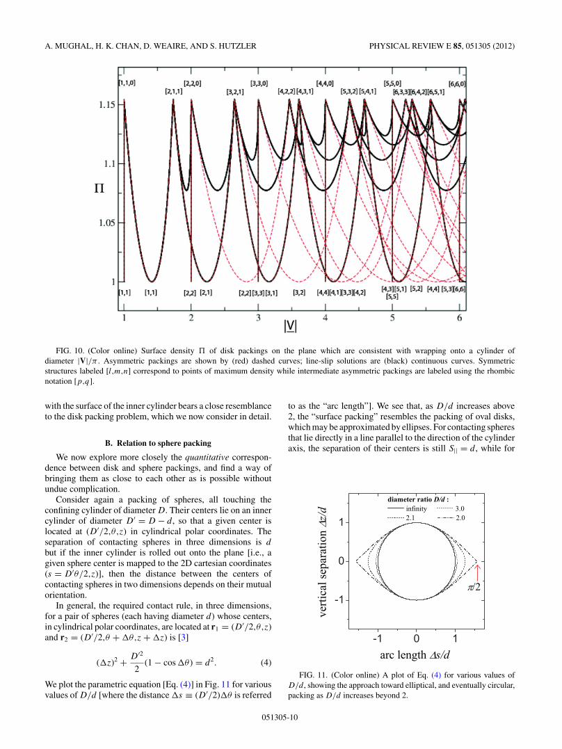
A. MUGHAL, H. K. CHAN, D. WEAIRE, AND S. HUTZLER PHYSICAL REVIEW E 85, 051305 (2012)
FIG. 10. (Color online) Surface density � of disk packings on the plane which are consistent with wrapping onto a cylinder ofdiameter |V|/π . Asymmetric packings are shown by (red) dashed curves; line-slip solutions are (black) continuous curves. Symmetricstructures labeled [l,m,n] correspond to points of maximum density while intermediate asymmetric packings are labeled using the rhombicnotation [p,q].
with the surface of the inner cylinder bears a close resemblanceto the disk packing problem, which we now consider in detail.
B. Relation to sphere packing
We now explore more closely the quantitative correspon-dence between disk and sphere packings, and find a way ofbringing them as close to each other as is possible withoutundue complication.
Consider again a packing of spheres, all touching theconfining cylinder of diameter D. Their centers lie on an innercylinder of diameter D′ = D − d, so that a given center islocated at (D′/2,θ,z) in cylindrical polar coordinates. Theseparation of contacting spheres in three dimensions is d
but if the inner cylinder is rolled out onto the plane [i.e., agiven sphere center is mapped to the 2D cartesian coordinates(s = D′θ/2,z)], then the distance between the centers ofcontacting spheres in two dimensions depends on their mutualorientation.
In general, the required contact rule, in three dimensions,for a pair of spheres (each having diameter d) whose centers,in cylindrical polar coordinates, are located at r1 = (D′/2,θ,z)and r2 = (D′/2,θ + �θ,z + �z) is [3]
(�z)2 + D′2
2(1 − cos �θ ) = d2. (4)
We plot the parametric equation [Eq. (4)] in Fig. 11 for variousvalues of D/d [where the distance �s ≡ (D′/2)�θ is referred
to as the “arc length”]. We see that, as D/d increases above2, the “surface packing” resembles the packing of oval disks,which may be approximated by ellipses. For contacting spheresthat lie directly in a line parallel to the direction of the cylinderaxis, the separation of their centers is still S|| = d, while for
FIG. 11. (Color online) A plot of Eq. (4) for various values ofD/d , showing the approach toward elliptical, and eventually circular,packing as D/d increases beyond 2.
051305-10

DENSE PACKINGS OF SPHERES IN CYLINDERS: . . . PHYSICAL REVIEW E 85, 051305 (2012)
FIG. 12. (Color online) Comparison of simulated and analytic volume fractions for the densest packings—upper and lower curves,respectively. Dotted lines are a guide for the eye to the detailed correspondence. In the analytic results, the line-slip structures are identified byblack continuous lines, and the red dashed-dotted lines denote asymmetric packing structures. The numbers 1, 2, and 3 (see text) denote thetype of line slip observed (upper curve) or predicted (lower curve) with 1\2 denoting a degenerate case. The shaded region on the right is thecontinuation of the single layered structures for D/d > 2.71486.
those that lie in the perpendicular plane, it is
S⊥ = D′ sin−1
(d
D′
). (5)
For simplicity we take the major and minor axes of the ellipseto have the S⊥ and S||, so that the distance on the plane for apair of contacting spheres is approximated by
S2 = d2 sin2(φ) +[D′ sin−1
(d
D′
)]2
cos2(φ). (6)
Comparing the circumference of the inner cylinder πD′with the length of the periodicity vector |V|d (i.e., measuredin units of the disk diameter d), gives a stretch factor,
X = πD′
|V|d = S⊥d
, (7)
where the last term is the ratio of the arc distance betweencontacting spheres, which lie perpendicular to the directionof the cylinder axis. In this way the sphere packing is relatedto the planar packing of elliptical disks, which is merely astretched version of a circular disk packing. Given any packingof circular disks in the plane, it may simply be stretched in thedirection of the vector V, by a factor X, and wrapped onto acylinder of diameter,
D′ = d
sin(π/|V|) , (8)
[obtained using Eqs. (5) and (7)], to create a good approxima-tion to a sphere packing.
Thus a correspondence that at first seems distant maybe brought much closer. Figure 12 presents the resultingtransformed curves for sphere packing density; asymmetricand line-slip structures are shown by red (dashed) and black(continuous) lines, respectively. The peaks in the densitycorrespond to symmetric packings. The lower (dashed) heavyblack line accentuates the curve of maximum density, aspredicted by our analytical approach. This is to be comparedwith the results of simulated annealing shown by the uppercurve. We have extended our simulated annealing study ofsingle layer packings to D > 2.71486, as shown by the grayregion in Fig. 12, by searching for the densest structures inwhich all the spheres have centers on the surface of a cylinderof diameter D′. From this we see that the maximum possibledensity, for single layer packings, is found at �(2.4863) =0.5446 and corresponds to the symmetric packing (5,3,2).Beyond this the packing density steadily diminishes sincespheres are to be found only on the surface of the cylinderand the interior is empty.
The analytical method presented here gives the correct line-slip solution in the majority of cases. There are, nevertheless,notable discrepancies between the analytical and numericalresults. These are due to the simplicity of the transformationused to map the disk packing problem into the sphere packingproblem; as a consequence, the analytical results always
051305-11

A. MUGHAL, H. K. CHAN, D. WEAIRE, AND S. HUTZLER PHYSICAL REVIEW E 85, 051305 (2012)
predict type (3) line-slip solutions leading up to n,n,0 packingwhile simulations in fact find a region split between a type(2) line slip followed immediately by a type (3) line slip. Amore accurate (and more complicated) transformation oughtto account for this by pushing the type (2) curve above the type(3) solution, for part of this region. This is borne out by thefact that as the diameter of the cylinder increases, and higherorder corrections to the transformation diminish in importance,the type (2) solution in the simulations are observed over anincreasingly smaller range in the split region.
VIII. STRUCTURES BEYOND D/D = 2.71486, WITHINTERNAL SPHERES
We are able to pursue the same simulations to highercylinder diameters, finding the anticipated occurrence ofinternal spheres, initially at D/d = 2.71486. The structuresinvolved are tabulated in the final section of Table I. In somecases phyllotactic notation may still be useful, but much of thesimplicity of the previous sections is lost, and increasingly so.The extension of the curve of volume fraction, as far as presentcomputing resources allow, is shown on the right-hand side ofFig. 3.
It is of the same general character as before; that is, weobserve peaks corresponding to maximal contact structures—which are labeled using the notation (u,v) in Table I— anddecreasing or increasing D/d yields structures with fewercontacts which can in some way be deformed steadily intothe maximal contact packing; these are labeled −(u,v) and+(u,v), respectively.
Packings with internal spheres are depicted in Fig. 13 wherein each case the middle diagram shows the entire structureviewed side-on. Although the introduction of inner spheresproduces more complicated structures there remains an outershell of spheres contacting the confining cylinder. The rolled-out pattern made by these outer spheres is shown to the left ofeach packing. The arrangement of the inner spheres is depictedin the diagram to the right of each packing, whereby the outerlayer is transparent and the inner spheres are in yellow.
The first packing with internal spheres is structure 30,or −(1,5), which consists of a basic unit cell containingsix spheres. Of these one sphere is not in contact with thecylindrical surface and is found at the center of the cylinder.The remaining five spheres, which are in contact with thecylinder, form a tilted pentagonal ring around the central sphere(i.e., tilted at an angle with respect to the plane perpendicularto the cylindrical axis). The extended structure can be madeby translating the unit cell along the cylinder and rotating itby π . The result is a chiral packing with an internal chain ofnoncontacting spheres along the cylindrical axis and an outerlayer of touching pentagonal rings. As can be seen, in thecorresponding rolled-out diagram of the outer layer in Fig. 13,there is only a single point of contact between outer ringscorresponding to a sphere with four surface neighbors. Thelocation of this sphere alternates by an azimuthal angle of π
between successive layers.Some of the spheres in the outer layer have only two
contacts with other spheres in the outer layer. However,mechanical stability is assured by their contact with the internal
chain of spheres and the average number of contacts per spherefor the structure as a whole is above four.
Increasing D/d reduces the tilt of the pentagonal ringsuntil at D/d = 2.7306 we have the maximal contact packing(1,5). Thus in structure 31 the spheres in the internal chain arein contact with each other and, compared with structure 30,there are now a greater number of contacts between successivepentagonal rings. Increasing D/d breaks some of these surfacecontacts and forces the chain of internal spheres to form atwisted zigzag structure. Thus structure 32, or +(1,5), is chiraland is superseded at D/d = 2.74804 by a new type of packing.
Structure 33, or −(1,10), consists of a basic unit cellcontaining 11 spheres. Of these 10 touch the cylindrical surfaceand are arranged as a pair of pentagonal rings stacked on topof each other. The 11th, internal sphere is found above the 10surface spheres and is located at the center of the cylinder. Theextended structure can be described as an alternating sequenceof surface spheres followed by an internal sphere. However,on average each sphere is only in contact with 40/11 = 3.636other spheres; this number is too low for mechanical stability,which we explain as follows.
As shown by the rolled-out diagram of the outer spherecenters, surface spheres from adjacent unit cells are not incontact. Thus the pairs of pentagonal rings are free to rotate,by a certain amount about the cylindrical axis while internalspheres remain fixed in position. Whether structure 33 isachiral or chiral depends on the relative orientation of thesurface spheres with respect to each other. No other optimalcylindrical packing yet discovered has this property.
With increasing D/d the pentagonal rings from adjacentunit cells are eventually locked into position at D/d = 2.8211to give (1,10). Thus packing 34 is a maximal contact achiralstructure, corresponding to a peak in Fig. 3. The spheres in theouter layer form a perfect rhombic [5,5] lattice when rolled outonto the plane and the internal spheres lie along the cylindricalaxis. An increase in D/d results in the loss of two contacts(on average) between the surface spheres and the internalspheres, and +(1,10) proceeds downward in density. As thetrend continues we observe a decrease in the separation ofneighboring internal spheres and a modulation in the rhombicsurface pattern; this latter symmetry breaking is responsiblefor structure 35 being a chiral structure.
Packing 36 includes an internal linear chain of noncon-tacting spheres lying along the central axis of the confiningcylinder. These are surrounded by an outer layer of sphereswhich form a complex chiral structure. As D/d is increasedthe spheres in the internal chain are brought ever closer toeach other until they make contact at D/d = 2.8615, whichcorresponds to the maximal contact, chiral structure 37.
A further increase in D/d forces the internal chain ofspheres to form a twisted zigzag structure. As a result there is aloss of two types of contacts: the breaking of contacts betweenspheres in the outer layer (as seen from the correspondingrolled-out pattern in Fig. 13) and a break in contact betweenspheres in the outer and inner layer. Thus there is a decreasein density as we proceed from structure 37 along 38 [i.e., aswe increase D/d for +(2,5)].
Structure 39 is remarkable in that we find an internal chainof spheres (along the central axis of the cylinder) but thechain is composed of a pair of touching spheres followed by
051305-12

DENSE PACKINGS OF SPHERES IN CYLINDERS: . . . PHYSICAL REVIEW E 85, 051305 (2012)
FIG. 13. (Color online) Structures with internal spheres. In the case of structures which are not maximal contact the images are producedfrom numerical results for arbitrarily chosen values of D/d within their ranges. The central image shows each structure viewed side-on. Theimage on the right shows the inner layer by making the outer layer transparent. The image on the left, for each packing, is the rolled outstructure generated by the outer layer of spheres which contact the cylindrical boundary - the periodicity vector V is indicated by the red arrow.
a gap; this is the structure −(2,13). Increasing D/d producesstructure 40, a maximal contact chiral packing (2,13), whichcompared with structure 39 has an increased number ofcontacts between internal-surface and surface-surface spheres.
This remarkable sequence of structures would have beendifficult to imagine in advance. It is likely to be followed by anequally rich scenario, whenever it becomes possible to pursuehigher values of D/d. The structures reported are new, to ourknowledge, except in so far as they correspond to dry foamstructures mentioned below in Sec. X.
IX. RELATED EXPERIMENTS
Columnar sphere packings appear in a variety of differentexperimental contexts, such as the packing of C60 buckyballsinside carbon nanotubes [16] and polystyrene spheres insidethe pores of silicone membranes [14]. The structures that arecommonly identified are the straight chain (structure 1 in ourTable I), zigzag (structure 2), twisted zigzag (structure 3), and
structure 5, although more complicated structures have alsobeen observed (e.g., [13]).
However, care needs to be taken when directly comparingthese experimental observations with the simple hard spheresimulations described here, which might well only serve as afirst guide of what structures to expect. The minimization ofinteraction energy may replace the maximization of density asthe guiding principle.
For example, the polystyrene particles in the experimentsof [14] have been charge-stabilized and thus repel each other.Unlike the situation in our simulations, this results in a prefer-ence to sit near the wall of the pores (i.e., the cylinder wall).
Furthermore the comparison of our simulation results withpackings of buckyballs might be limited. Experiments by [16]show that while it is possible to fill C60 into double-wallednanotubes down to the ratio D/d = 1.13 (resulting in a simplelinear chain), it is not possible to fill single-walled carbonnanotubes below D/d = 1.25 (D is the inner diameter of thetube in both cases). This reflects the role of the van der Waalsforces between C60 and the confining nanotube walls.
051305-13

A. MUGHAL, H. K. CHAN, D. WEAIRE, AND S. HUTZLER PHYSICAL REVIEW E 85, 051305 (2012)
A. Present experiments with ball bearings and bubbles
However, we have identified two other experimental sys-tems that provide very good comparison with our simulationdata (details to be provided in a follow-up paper).
The first are metal spheres of a few millimeter in diameter(the type used in “ball bearings”) packed into perspextubes. The filled tubes were mechanically agitated over anextended period. At the end of this “annealing” procedure thisresulted in clearly identifiable ordered sphere packings. Theseexperiments were carried out for a large range of values ofD/d (up to 3.15), and resulted in about 16 different structures,of both the maximal contact and the line-slip type.
We have also carried out more extensive experiments withequal-volume gas bubbles (with diameter of a few hundredmicrons). These are produced by bubbling gas into surfactantsolution with the bubble diameter easily variable by adjustingthe gas flow.
The bubbles are then gathered into vertically placedcylinders. They maintain a (nearly) spherical shape, evenwhen in contact, up to a column height of a few millimeters,corresponding to the capillary length for the surfactant solutionin use.
We were able to produce straight chain, zigzag, and alarge number of maximal contact structures, and also manystructures with internal bubbles, up to and well beyond thepoint reached by the present simulations. There is also someevidence of the twisted zigzag structure and line-slip struc-tures. The subsequent paper presenting these experimentallyobtained structures will include the use of x-ray tomographyto establish their internal configurations.
B. Ordered dry foam structures
Extensive and detailed results have been published for thevarious structures that form when equal volume bubbles withdiameter exceeding a few millimeters (i.e., larger than thecapillary length) are collected in vertical tubes [8,22]. In thiscase, the liquid drains and a dry foam is created—a packing ofpolyhedral bubbles, with its volume fraction � approachingunity.
The surface pattern displayed by these ordered foams ishexagonal (apart from the so-called bamboo structure whichis simply an array of parallel soap films). The phyllotacticnotation is thus the obvious choice for their classification, atleast as long as there are no internal bubbles (see, e.g., Fig. 14).
Restricting ourselves for the moment to this case it wouldappear that all ordered dry foam structures have correspondingsphere packings (wet foams) (i.e., they can be classified bythe same phyllotactic notation). These include the straightchain (bamboo) and zigzag structure (called 2-1-1 or staircasestructure in the foam literature), and all of the 10 maximalcontact structures, except structure 25 (5-4-1) which has notyet been observed. None of the ordered dry foam structures isof the line-slip type.
Note that since the bubbles are deformable, the averagecontact number in the case of dry foams is generally higherthan in hard sphere packings.
Unlike their sphere packing counterparts, the various dryfoam structures are found over ranges of values of D/d (inthe foams literature d refers to the equivalent sphere diameter
FIG. 14. (Color online) In the dry foam equivalent of the zigzagstructure (often called the staircase structure) equal-volume gasbubbles are separated by thin liquid films. (a) Computer simula-tion using the SURFACE EVOLVER software of Ken Brakke [23].(b) Photograph of bubbles in a cylinder of about 1 cm in diameter.
of a bubble). Hysteresis plays a large role in the standardexperimental procedure, leading to overlapping ranges ofstability for the various structures.
The structure of minimal energy for a given value of D/d
may be determined from computer simulations [22,24–27].We find these ranges always to be lower than the value ofD/d for the corresponding sphere packing, reflecting theirmuch smaller volume fractions. It remains for future researchto establish the phase diagram (which may be rather complex)that connects these two limiting cases.
There are also observations of over 20 different ordereddry foam structures with internal bubbles [8], but the preciseinternal arrangements have only been identified for the threesimplest cases, with the aid of SURFACE EVOLVER simulations[23,26].
The dry foam with a surface pattern equivalent to structure28 (C5) has six bubbles in the periodic unit cell (i.e., onemore than C5). A pentagonal dodecahedron in the center ofthe cylinder is surrounded by a ring of five bubbles in contactwith the cylinder surface. The dodecahedra of neighboring unitcells are in contact.
There is also a foam structure with a so-called Kelvin cell(tetracaidecahedron) in the center, surrounded by six bubblesin contact with the surface. Again the internal bubbles ofneighboring unit cells are in contact with each other.
The third identified structure with internal bubbles consistsof a total of 13 bubbles in the unit cell, 12 touching the surface,and a bubble with 12 pentagons and three hexagons (Goldberg-3) in the center [26]. Interestingly, in this case the internalbubbles of neighboring unit cells are not in contact, similar tothe also achiral structure 34. The surface pattern of this foamstructure consists of an arrangement of bi-disperse hexagons.
X. CONCLUSIONS
Our simulations have provided detailed results for 40distinct columnar crystals, of which many are new. They
051305-14

DENSE PACKINGS OF SPHERES IN CYLINDERS: . . . PHYSICAL REVIEW E 85, 051305 (2012)
fall into three categories: the very simplest cases, where thesphere diameter is of the same order as that of the cylinder,a wide range of further “phyllotactic” structures, which maybe understood as related to surface packings of disks, andstructures that incorporate internal spheres.
Corresponding experimental observations are now avail-able and will be reported in a second paper. Experimentscan already be pushed to much larger cylinder diameters,providing further insights and challenges to simulation andinterpretation.
Such a further development should motivate a reassessmentof the simulation methods to be used; we make no strong claimsfor the efficiency of that used here. We have necessarily beencautious in using it, stipulating high degrees of convergenceand undertaking many repeated runs in search of the optimum,to increase confidence in our conclusions. In parallel studies,Chan [3] used a sequential deposition method that washighly expeditious in determining optimal structures withinthe restriction of that procedure, whose effect could not beknown a priori. Suitably adapted, it was able to reproduce thestructures reported here, up to at least D/d = 2.7013. Futurework will include an extension of this deposition approach tohigher values of D/d.
Finally we note some possible extensions to this work. Anexample is the study of disordered hard sphere packings ina cylinder; for such problems the definition of the volumefraction recently given by Chan [3] may prove useful. Asimple problem that may be of significant practical interestis to find the densest packing of hard spheres in a cylinderwhich is capped on either side by hard walls (i.e., packingin a cylindrical box). Even richer possibilities are offeredby packing hard sphere in a cylinder that is capped on bothends by spheres held in a fixed position. Indeed, hard spherepackings that are bounded by templated surfaces on all sidesare of significant current interest and are capable of realizing arange of different morphologies (including the Weaire-Phelanstructure) [28].
ACKNOWLEDGMENTS
This research was supported by Science Foundation Ireland(Grant No. 08-RFP-MTR1083) and European Space Agency(MAP Grants No. AO-99-108:C14914/02/NL/SH and No.AO-99-075:C14308/00/NL/SH). H.K.C. acknowledges sup-port from the Irish Research Council for Science, Engineeringand Technology (EMPOWER Fellowship).
APPENDIX A: SIMULATION TECHNIQUE
1. Energy function
The simulation is addressed to a cylindrically shaped cellof length L and diameter D. Contained within this spaceare N points which represent the centers of N spheres, eachof diameter d. If a pair of spheres is sufficiently close thatthey overlap we account for this using a pairwise potential asdescribed below. A similar overlap potential is used to preventthe spheres from escaping the simulation cell in the radialdirection. The final structures will be the densest that we findwhich have zero overlap energy.
In addition, we impose twisted periodic boundary condi-tions on the top and bottom of the cylindrical cell as describedin the main text, with a twist angle α.
We model the overlap potential between spheres using aHookean, or “springlike,” pairwise interaction between the ithand j th spheres, which have their centers at ri = (ri,θi,zi) andrj = (rj ,θj ,zj ); the interaction energy between spheres is thengiven by
ESij =
{12 (rij − d)2 if rij � d,
0 if rij > d,(A1)
where rij = |ri − rj | is the distance between the centers of thespheres. Note the interaction energy falls to zero when thereis no overlap between the spheres.
The interaction energy between the ith sphere and theboundary is given by
EBi =
{12 (riB − d/2)2 if riB � d/2,
0 if riB > d/2,(A2)
where riB = |D/2 − ri |.The twisted periodic boundary conditions on the ends of
the cylinder are incorporated as follows: The ith particlein the simulation cell has an image at the top and bottomof the simulation cell; the coordinates of these images aregiven by r+
i = (ri,θi + α,zi + L) and r−i = (ri,θi − α,zi −
L), respectively, where L is the length of the cylinder andα is the twist angle.
Thus the total energy of the system is given by thesum of the sphere-sphere, sphere-boundary, and sphere-imageinteractions.
2. Numerical method
For a tube of diameter D we wish to find the unit cell,composed of N spheres, which when rotated and stacked alongthe tube has the highest volume fraction. In this section wedescribe the simulation protocol used to achieve this.
For a given D and d we assign initial starting positionsto the N spheres and an initial value to the twist angle α byusing a random number generator. A small initial value forthe cylinder length L is chosen to ensure overlap between thespheres.
Keeping D and L fixed, we search for the lowest energyarrangement for the N spheres by varying their coordinates andthe twist angle. This is done using the standard METROPOLIS
simulated annealing algorithm, where for a cluster of N
spheres the algorithm was run with typically N × (5 × 10⁶)Monte Carlo steps. The temperature of the simulation wasdecreased linearly. The average displacement of the spheres ateach temperature step was chosen by an automatic process togive an acceptance probability of 0.5 ± 0.01. The results of thesimulated annealing are then put through a conjugate gradientroutine to ensure that a local minimum has been reached.
The whole process is repeated many times, using a newrandomly generated initial configuration, to give confidencethat the lowest energy state has been found. From this ensemblewe take the lowest energy configuration as the final state forthat particular run.
051305-15

A. MUGHAL, H. K. CHAN, D. WEAIRE, AND S. HUTZLER PHYSICAL REVIEW E 85, 051305 (2012)
After this first run we perform a subsequent run with aslightly longer cylinder. Since the spheres have more room theenergy of the final state is lower compared to the final stateof the previous run. Using a divide-and-conquer approach weare able to establish the cell length at which the energy persphere in the system falls to zero; in practice this means thevalue of the energy is within a critical bound which is setto be E/n = 1 × 10⁻⁸ ± 5 × 10⁻⁹. At this point the sphereshave a small overlap corresponding to a five decimal placeaccuracy in the volume fraction (this is deduced by comparingsimulation with the analytically derived volume fraction forthe CN circle packing structures).
From this final result we compute the volume fraction whichis defined as
�(N,D) = NVs
Vc
, (A3)
where Vs = (4/3)π (d/2)3 is the volume of one of the hardspheres and Vc = π (D/2)2L is the volume of the simulationcell. Note that the volume fraction depends on both D andN since different values of N yield unit cells with differentstructures. Thus the whole procedure is repeated for a series ofdifferent values of N = 1,2,3 . . ., typically up N = 15 for thestructures without internal spheres, before accepting the onewhich gives the largest volume fraction, as shown in Table I.
APPENDIX B: CONTINUITY OF THE VOLUME FRACTION
We demonstrate that there can be no sudden finite dis-continuities in the curve describing the maximum volumefraction (density) as D/d is varied. This follows from lowerand upper bounds, as described below, which limit the variationin volume fraction in the neighborhood of any point D0/d0. Wewill see that square-root singularities observed in the numericalresults for the volume fraction are due to the arguments givenbelow.
1. Lower bound
For increasing D/d an obvious variational argumentbounds the density below. As D/d is increased from D0/d0,the cylinder expands radially. We may take the structurewhich has maximum density at D0/d0 as a trial structure forD/d > D0/d0. The volume fraction of the structure, at D0/d0,is
�(D0/d0) = Vs
π (D0/2)2L, (B1)
and that of the trial structure is
�T(D/d) = Vs
π (D/2)2L, (B2)
where Vs = Vs(d) is the volume of a sphere of diameter d, andL is the average separation between spheres in the z direction.Since �T(D0/d0) = �(D0/d0) it follows that
�T(D/d) >D2
0
D2�(D0/d0), (B3)
providing a lower bound for D > D0.
2. Upper bound
For decreasing D/d, a more subtle argument boundsthe variation of density below by a square-root function.Decreasing D/d forces the spheres to move radially inwardto avoid contact with the cylindrical boundary. The resultingoverlap between spheres can be eliminated by displacement oftheir centers parallel to the cylinder axis.
Let us index the sphere centers in ascending height usingthe index j so that zj > zj−1 for j > j − 1. Given thestructure at D0/d0 which has a maximum density, then anextreme case is one where successive spheres all have thesame height. Consider in this case a pair of contacting sphereswith separation d. Reducing the cylinder diameter by a factorof X, so that the new diameter is D = D0X, will force anoverlap so that the separation between sphere centers is nowdX. The overlap can be removed by moving one of the spheresvertically a distance �, so that their separation is once againd. It follows that d2 = �2 − (dX)2. Thus a constant C can bechosen so that the following choice is sufficient,
� = C
√D2
0 − D2. (B4)
In order to eliminate the overlap, the sphere centers are shiftedto a new height z′
j = zj + j�. The resulting trial structure hasthe volume fraction,
�T = Vs
π (D/2)2(L + �), (B5)
which when combined with Eq. (B1) results in the followingbound:
�T (D/d) <D2
0
D2
L
L + ��(D0/d0). (B6)
Hence we again arrive at a (lower) bound for �T (D/d) whichgoes continuously to �(D0/d0) as D/d → D0/d0 but in thiscase with a square-root form.
[1] G. T. Pickett, M. Gross, and H. Okuyama, Phys. Rev. Lett. 85,3652 (2000).
[2] A. Mughal, H. K. Chan, and D. Weaire, Phys. Rev. Lett. 106,115704 (2011).
[3] H. K. Chan, Phys. Rev. E 84, 050302(R) (2011).[4] A. Meagher (in preparation).[5] R. O. Erickson, Science 181, 705 (1973).[6] N. Pittet, P. Boltenhagen, N. Rivier, and D. Weaire, Europhys.
Lett. 35, 547 (1996).
[7] D. Weaire, S. Hutzler, and N. Pittet, Forma 7, 259 (1992).[8] N. Pittet, N. Rivier, and D. Weaire, Forma 10, 65
(1995).[9] P. Boltenhagen, N. Pittet, and N. Rivier, Europhys. Lett. 43, 690
(1998).[10] S. Hutzler, D. Weaire, F. Elias, and E. Janiaud, Philos. Mag.
Lett. 82, 297 (2002).[11] J. H. Moon, S. Kim, G. R. Yi, Y. H. Lee, and S. M. Yang,
Langmuir 20, 2033 (2004).
051305-16

DENSE PACKINGS OF SPHERES IN CYLINDERS: . . . PHYSICAL REVIEW E 85, 051305 (2012)
[12] J. H. Moon, G. R. Yi, and S. M. Yang, J. Coll. Int. Sci. 287, 173(2005).
[13] F. Li, X. Badel, J. Linnros, and J. Wiley, J. Am. Chem. Soc. 27,7262 (2005).
[14] M. Tymczenko, L. F. Marsal, T. Trifonov, I. Rodriguez,F. Ramiro-Manzano, J. Pallares, A. Rodriguez, R. Alcubilla,and F. Meseguer, Adv. Mater. 20, 2315 (2008).
[15] M. A. Lohr, A. M. Alsayed, B. G. Chen, Z. Zhang, R. D. Kamien,and A. G. Yodh, Phys. Rev. E 81, 040401(R) (2010).
[16] A. N. Khlobystov, D. A. Britz, A. Ardavan, and G. A. Briggs,Phys. Rev. Lett. 92, 245507 (2004).
[17] T. Yamazaki, K. Kuramochi, D. Takagi, Y. Homma,F. Nishimura, N. Hori, K. Watanabe, S. Suzuki, andY. Kobayashi, Nanotechnology 19, 045702 (2008).
[18] J. Warner and M. Wilson, ACS Nano 4, 4011 (2010).[19] T. Aste and D. Weaire, The Pursuit of Perfect Packing, 2nd ed.
(CRC Press, Boca Raton, 2008).
[20] T. Hales, Discrete Comput. Geom. 36, 1 (2006).[21] H. Airy, Proc. R. Soc. 21, 176 (1872).[22] S. Tobin, J. Barry, A. Meagher, B. Bulfin,
C. O’Rathaille, and S. Hutzler, Colloids Surf. A 382, 24(2011).
[23] K. A. Brakke, Exp. Math. 1, 141 (1992).[24] D. Weaire and R. Phelan, Phil. Trans.: Math. 354, 1989
(1996).[25] D. Weaire, G. Bradley, and R. Phelan, Soft Condensed
Matter: Configurations, Dynamics and Functionality (KluwerAcademic, Norwell, 2000).
[26] M. Saadatfar, J. Barry, D. Weaire, and S. Hutzler, Philos. Mag.Lett. 88, 661 (2008).
[27] S. Hutzler, J. Barry, P. Grasland-Mongrain, and D. Weaire,Colloids Surf. A 344, 37 (2009).
[28] R. Gabbrielli, A. Meagher, D. Weaire, K. Brakke, and S. Hutzler,Philos. Mag. Lett. 92, 1 (2012).
051305-17


![Self-organization of complex networks as a dynamical systemaoki/papers/PhysRevE.91.012908.pdf · [1,2]. Moreover, many types of dynamical processes on the networks have been studied](https://img.pdfslide.us/doc/110x75/5edafac609ac2c67fa689db8/self-organization-of-complex-networks-as-a-dynamical-aokipapersphysreve91012908pdf.jpg)