Embed Size (px)
Citation preview
8/9/2019 PhysicsA2 OptionAstrophysics Telescopes
http://slidepdf.com/reader/full/physicsa2-optionastrophysics-telescopes 1/27
Astrophysics
Chapter 1 Telescopes
1.1 Lenses
Learning objectives:
What is a converging lens and what is its focallength?
How does a converging lens form an image?
How can we predict the position andmagnification of an image formed by aconverging lens?
The converging lensLenses are used in optical devices such as the camera and the telescope. A lens works by
changing the direction of light at each of its two surfaces. Figure 1 shows the effect of aconverging lens and of a diverging lens on a beam of parallel light rays.
Figure 1 Focal length
A converging lens makes parallel rays converge to a focus. The point where parallel rays arefocused to is called the principal focus or the focal point of the lens.
A diverging lens makes parallel rays diverge (i.e. spread out). The point where the rays
appear to come from is the principal focus or focal point of this type of lens.
In both cases, the distance from the lens to the principal focus is the focal length of the lens. Inthis option, we consider the converging lens only.
© Oxford University Press 2014 http://www.oxfordsecondary.co.uk/acknowledgements
This resource sheet may have been changed from the original. 1

8/9/2019 PhysicsA2 OptionAstrophysics Telescopes
http://slidepdf.com/reader/full/physicsa2-optionastrophysics-telescopes 2/27
Astrophysics
Note
The plane on each side of the lens perpendicular to the principal axis containing the principal
focus is called the focal plane.
Investigating the converging lensThe arrangement in Figure 2 can be used to investigate the image formed by a converging lens.
Light rays illuminate the crosswires which form the object. These light rays are refracted by thelens such that the rays form an image of the crosswires.
Figure 2 Investigating images 1 With the object at different distances beyond the principal focus of the lens, the position
of the screen is adjusted until a clear image of the object is seen on the screen. The image isdescribed as a real image because it is formed on the screen where the light rays meet. If the
object is moved nearer the lens towards its principal focus, the screen must be moved furtherfrom the lens to see a clear image. The nearer the object is to the lens, the larger the image is.
2 With the object nearer to the lens than the principal focus, a magnified image is formed.The lens acts as a magnifying glass. But the image can only be seen when you look into thelens from the other side to the object. The image is called a virtual image because it isformed where the light rays appear to come from.
Ray diagramsThe position and nature of the image formed by a lens depends on the focal length of the lens andthe distance from the object to the lens.
If we know the focal length, f , and the object distance, u, we can find the position and nature ofthe image by drawing a ray diagram to scale in which:
the lens is assumed to be thin so it can represented by a single line at which refraction takes place
the straight line through the centre of the lens perpendicular to the lens is called the principalaxis
the principal focus F is marked on the principal axis at the same distance from the lens on
each side of the lens
the object is represented by an ‘upright’ arrow as shown in Figure 3.
Note that the ‘horizontal’ scale of the diagram must be chosen to enable you to fit the object, the
image and the lens on the diagram.
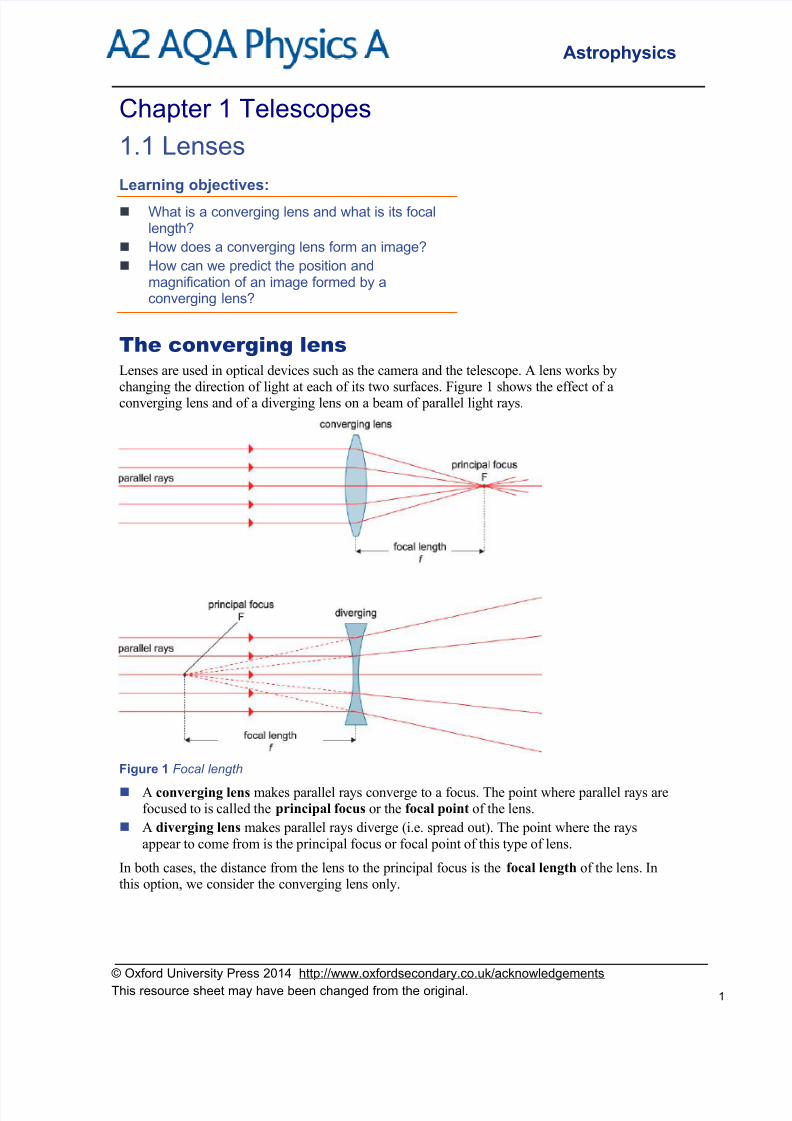
Formation of a real image by a converging lensTo form a real image, the object must be beyond the principal focus F of the lens. The image is
formed on the other side of the lens to the object.
© Oxford University Press 2014 http://www.oxfordsecondary.co.uk/acknowledgements
This resource sheet may have been changed from the original. 2
8/9/2019 PhysicsA2 OptionAstrophysics Telescopes
http://slidepdf.com/reader/full/physicsa2-optionastrophysics-telescopes 3/27
Astrophysics
Figure 3 Formation of a real image by a converging lens
To locate the tip of the image, three key ‘construction’ rays from the tip of the object are drawn, through the lens. The tip of the image is formed where these three rays meet. The image is real
and inverted.
1 Ray 1 is drawn parallel to the principal axis before the lens so it is refracted by the lens
through F.2 Ray 2 is drawn through the lens at its centre without change of direction. This is because the
lens is thin and its surfaces are parallel to each other at the axis.
3 Ray 3 is drawn through F before the lens so it is refracted by the lens parallel to the axis.
Figure 4(a) and 4(b) show ray diagrams for the object at 2F and between F and 2F respectively.
The results for Figures 3 and 4 are described in the table below. Notice that the image is:
diminished in size when the object is beyond 2F as in Figure 3
the same size as the object when the object is at 2F as in Figure 4(a)
magnified when the object is between F and 2F as in Figure 4(b).
Figure 4 Using ray diagrams to locate an image
© Oxford University Press 2014 http://www.oxfordsecondary.co.uk/acknowledgements
This resource sheet may have been changed from the original. 3
8/9/2019 PhysicsA2 OptionAstrophysics Telescopes
http://slidepdf.com/reader/full/physicsa2-optionastrophysics-telescopes 4/27
Astrophysics
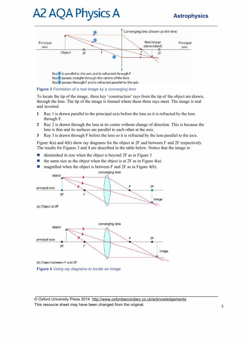
Formation of a virtual image by a converging lensThe object must be between the lens and its principal focus, as shown in Figure 5. The image isformed on the same side of the lens as the object.
Figure 5 Virtual image by a converging lens
Figure 5 shows that the image is virtual, upright and larger than the object. The image is on thesame side of the lens as the object and can only be seen by looking at it through the lens. This is
how a magnifying glass works.
If the object is placed in the focal plane, light rays from any point on the object are refracted bythe lens to form a parallel beam. A viewer looking at the object through the lens would thereforesee a virtual image of the object at infinity.
Object position Image position Natureofimage
Magnified ordiminished
Upright orinverted
Application
beyond 2F between F and 2F real diminished inverted camera
2F 2F real same size inverted inverter
between F and 2F beyond 2F real magnified inverted projector
< F same side as object virtual magnified upright magnifyinglens
Table 1 Image formation by a converging lens
Note
The linear magnification of the image =objecttheof height
imagetheof height
It can be shown that this ratio is equal todistanceobjectthe
distanceimagethe
The image is said to be magnified if the image height is greater than the object height anddiminished if it is smaller.
When you draw a ray diagram, make sure you choose asuitably large scale that enables you to fit the object andthe image on your diagram – and use a ruler to make sureyour lines are straight!
© Oxford University Press 2014 http://www.oxfordsecondary.co.uk/acknowledgements
This resource sheet may have been changed from the original. 4

8/9/2019 PhysicsA2 OptionAstrophysics Telescopes
http://slidepdf.com/reader/full/physicsa2-optionastrophysics-telescopes 5/27
Astrophysics
The lens formulaFor an object on the principal axis of a thin lens of focal length f at distance u from the lens, thedistance, v, from the image to the lens is given by
f v u
111
Notes
1 Proof of the lens formula is not required for this specification.
2 When numerical values are substituted into the formula, the sign convention
real is positive; virtual is negative
is used for the object and image distances. The focal length, f , for a converging lens is alwaysassigned a positive value. A diverging lens is always assigned a negative value.
Worked example
An object is placed on the principal axis of a convex lens of focal length 150 mm at a distance of
200 mm from the centre of the lens.
a Calculate the image distance.
b State the properties of the image.
Solut ion
a f = +0.150 m, u = +0.200 mm
Using the lens formula f vu
11
1 gives
150.0
11
200.0
1
v
Hence200.0
1
150.0
11
v = 6.67 − 5.00 = 1.67
Therefore v = +0.600 m
b The image is real (because v is positive), inverted and magnified (because v > u).
Summary questions
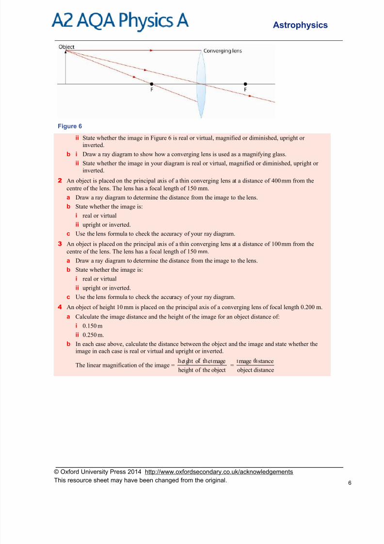
1 a i Copy and complete the ray diagram in Figure 6 to show how a converging lens in a camera forms
an image of an object.
© Oxford University Press 2014 http://www.oxfordsecondary.co.uk/acknowledgements
This resource sheet may have been changed from the original. 5
8/9/2019 PhysicsA2 OptionAstrophysics Telescopes
http://slidepdf.com/reader/full/physicsa2-optionastrophysics-telescopes 6/27
Astrophysics
Figure 6
ii State whether the image in Figure 6 is real or virtual, magnified or diminished, upright or
inverted.
b i Draw a ray diagram to show how a converging lens is used as a magnifying glass.
ii State whether the image in your diagram is real or virtual, magnified or diminished, upright or
inverted.
2 An object is placed on the principal axis of a thin converging lens at a distance of 400 mm from the
centre of the lens. The lens has a focal length of 150
mm.a Draw a ray diagram to determine the distance from the image to the lens.
b State whether the image is:
i real or virtual
ii upright or inverted.
c Use the lens formula to check the accuracy of your ray diagram.
3 An object is placed on the principal axis of a thin converging lens at a distance of 100 mm from the
centre of the lens. The lens has a focal length of 150 mm.
a Draw a ray diagram to determine the distance from the image to the lens.
b State whether the image is:
i real or virtual
ii upright or inverted.
c Use the lens formula to check the accuracy of your ray diagram.
4 An object of height 10 mm is placed on the principal axis of a converging lens of focal length 0.200 m.
a Calculate the image distance and the height of the image for an object distance of:
i 0.150 m
ii 0.250 m.
b In each case above, calculate the distance between the object and the image and state whether the
image in each case is real or virtual and upright or inverted.
The linear magnification of the image =objecttheof height
maget eoe g t=
distanceobject
stancemage
© Oxford University Press 2014 http://www.oxfordsecondary.co.uk/acknowledgements
This resource sheet may have been changed from the original. 6

8/9/2019 PhysicsA2 OptionAstrophysics Telescopes
http://slidepdf.com/reader/full/physicsa2-optionastrophysics-telescopes 7/27
Astrophysics
1.2 The refracting telescope
Learning objectives:
What is a refracting telescope?
What do we mean by angular magnification?
How does the angular magnification depend onthe focal lengths of the two lenses?
The astronomical telescope consisting of two
converging lensesTo make a simple refracting telescope, two converging lenses of differing focal lengths are
needed. The lens with the longer focal length is referred to as the objective because it faces theobject. The viewer needs to look through the other lens, the eyepiece, as shown in Figure 1. Lightfrom the object enters his or her eye after passing through the objective then through the eyepiece
into the viewer’s eye. By adjusting the position of the inner tube in the outer tube, the distance between the two lenses is altered until the image of the distant object is seen in focus. If thetelescope is used to view a distant terrestrial object, the viewer sees an enlarged, virtual andinverted image.
Figure 1 The simple refracting telescope
To understand why the viewer sees a magnified virtual image, consider the effect of each lens onthe light rays from the object that enter the telescope:
The objective lens focuses the light rays to form a real image of the object. This image isformed in the same plane as the principal focus of the objective lens which is where the lightrays cross each other after passing through the objective lens. If a ‘tracing paper’ screen is
placed at this position, as shown in Figure 2, the real image formed by the objective can be
seen directly on the paper without looking through the eyepiece.
© Oxford University Press 2014 http://www.oxfordsecondary.co.uk/acknowledgements
This resource sheet may have been changed from the original. 7

8/9/2019 PhysicsA2 OptionAstrophysics Telescopes
http://slidepdf.com/reader/full/physicsa2-optionastrophysics-telescopes 8/27
Astrophysics
The eyepiece gives the viewer looking through the telescope a magnified view of this realimage with or without the tracing paper present. If the tracing paper is removed, the viewer
sees the same magnified view of the real image except much brighter. This magnified view isa virtual image because it is formed where the rays emerging from the eyepiece appear tohave come from.
The virtual image is inverted compared with the distant object. This is because the real imageformed by the objective is inverted and the final virtual image is therefore inverted compared
with the distant object.
Figure 2 Investigating the simple refracting telescope
The ray diagram in Figure 3 shows in detail how the viewer looking through the eyepiece sees the
final virtual image. The diagram shows the telescope in normal adjustment which means thetelescope is adjusted so the virtual image seen by the viewer is at infinity. In this situation, the
principal focus of the eyepiece is at the same position as the principal focus of the objective. In
other words, in normal adjustment:
the distance between the two lenses is the sum of their focal lengths
This is because:
the real image of the distant object is formed in the focal plane of the objective (because thelight rays from each point of the object are parallel to each other before entering the objective
lens)
the eyepiece is adjusted so its focal plane coincides with the focal plane of the objective. As aresult, the light rays that form each point of the real image leave the eyepiece parallel to oneanother. To the viewer looking into the eyepiece, these rays appear to come from a virtualimage at infinity.
Figure 3 Ray diagram for a simple refracting telescope in normal adjustment
© Oxford University Press 2014 http://www.oxfordsecondary.co.uk/acknowledgements
This resource sheet may have been changed from the original. 8
8/9/2019 PhysicsA2 OptionAstrophysics Telescopes
http://slidepdf.com/reader/full/physicsa2-optionastrophysics-telescopes 9/27
Astrophysics
Notes
1 The light rays from each point of the distant object:
are effectively parallel to each other by the time they reach the telescope
leave the telescope as a parallel beam which therefore appears to the viewer to come froma distant point.
2 The real image formed by the objective lens is inverted and diminished in size. The eyepiecein effect acts as a magnifying glass with the real image being viewed by it. The viewer sees a
magnified virtual image which is ‘upright’ compared with the real image and thereforeinverted compared with the distant object.
3 Notice that all the light rays from the object that pass through the eyepiece all pass through a
circle referred to as the ‘eye-ring’. This is the best position for the viewer’s eye as the entireimage can be seen by the eye at this position.
Angular magnification
Application
Investigating the simple refracting telescope
Use two suitable converging lenses in holders to make a simple refracting telescope. Adjust the position of the eyepiece so an image of a distant object is seen in focus. The image of the object is
inverted and it should be magnified.
Place a ‘tracing paper’ screen between the lenses and locate the real image of the distant object
formed by the objective lens. Observe the image directly and through the eyepiece to see that the
eyepiece gives a magnified virtual image of the real image. The virtual image becomes brighter if
the screen is removed.
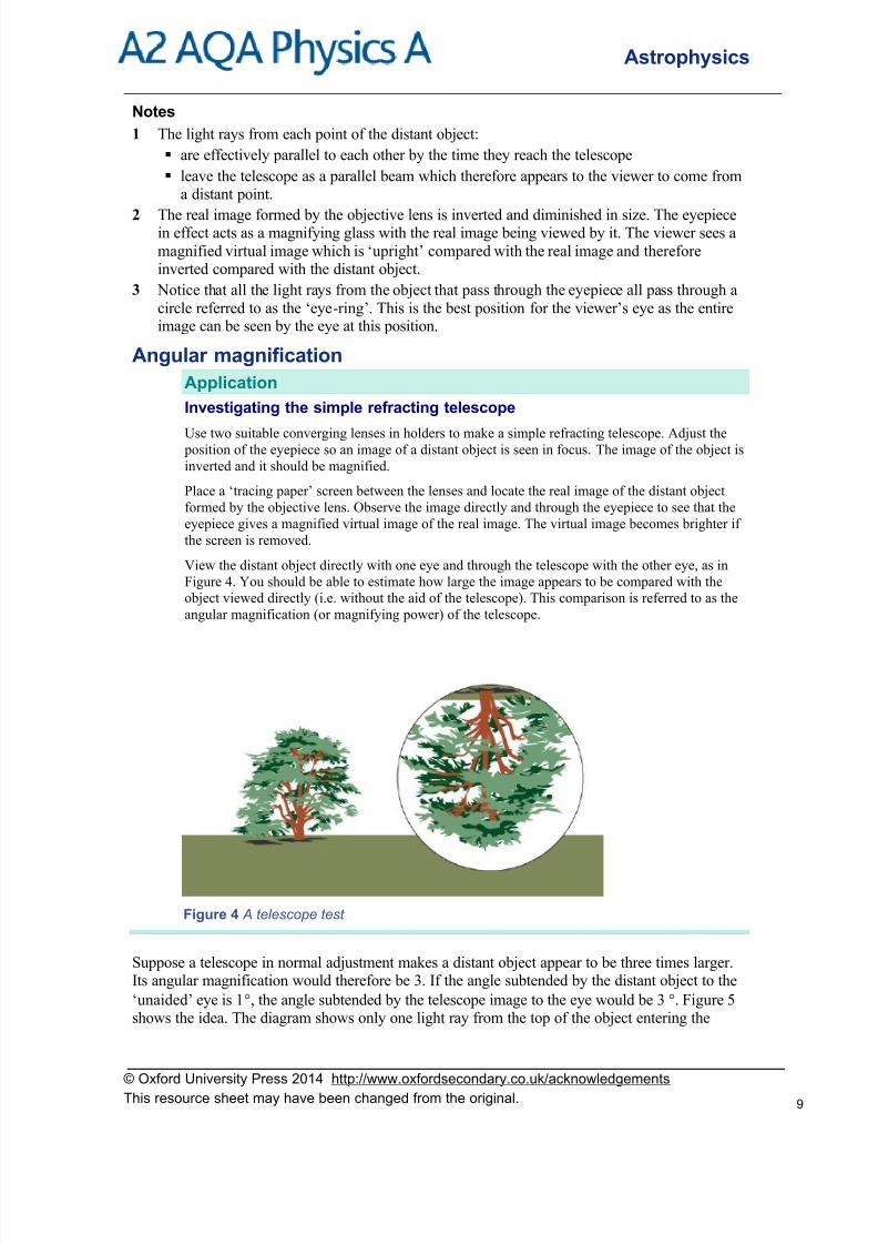
View the distant object directly with one eye and through the telescope with the other eye, as in
Figure 4. You should be able to estimate how large the image appears to be compared with the
object viewed directly (i.e. without the aid of the telescope). This comparison is referred to as the
angular magnification (or magnifying power) of the telescope.
Figure 4 A telescope test
Suppose a telescope in normal adjustment makes a distant object appear to be three times larger.Its angular magnification would therefore be 3. If the angle subtended by the distant object to the
‘unaided’ eye is 1, the angle subtended by the telescope image to the eye would be 3. Figure 5shows the idea. The diagram shows only one light ray from the top of the object entering the
© Oxford University Press 2014 http://www.oxfordsecondary.co.uk/acknowledgements
This resource sheet may have been changed from the original. 9

8/9/2019 PhysicsA2 OptionAstrophysics Telescopes
http://slidepdf.com/reader/full/physicsa2-optionastrophysics-telescopes 10/27
Astrophysics
telescope at the objective lens and leaving in a direction as if it was from the tip of the virtualimage seen by the viewer. The distant object and the image are meant to be at infinity so the angle
subtended by the distant object to the unaided eye is effectively the same as the angle subtended by the object to the telescope.
The angle subtended by the final image at infinity to the viewer =
The angle subtended by the distant object to the unaided eye =
The angular magnification of the telescope in normal adjustment =
eyeunaidedthetoobjectdistantthebysubtendedangle
viewerthetoinfinityatimagefinalthebysubtendedangle
Figure 5 Angular magnification
From the inset diagram in Figure 5, it can be seen that tan =o
1
f
hand tan =
e
1
f
h, where h1 is the
height of the real image and f o and f e are the focal lengths of the objective and eyepiece lenses
respectively.
Combining these two equations to eliminate h1 givese
o
o
1
e
1
tantan
f f
f h f
h
Assuming angles and are always less than about 10, applying the small angle approximation
tan = in radians and tan = in radians givese
o
f
f
Therefore:
© Oxford University Press 2014 http://www.oxfordsecondary.co.uk/acknowledgements
This resource sheet may have been changed from the original. 10

8/9/2019 PhysicsA2 OptionAstrophysics Telescopes
http://slidepdf.com/reader/full/physicsa2-optionastrophysics-telescopes 11/27
Astrophysics
the angular magnification of a telescope in normal adjustment =e
o
f
f
Notes
1 The height h1 of the real image = f o tan = f o × ( in radians)
Remember 360 = 2 radians.
2 The objective is the lens with the longer focal length. If you use a telescope the wrong wayround, you will see a diminished image!
Always check your calculator is in the correct ‘angle’ modewhen carrying out calculations involving angles.
Worked example
A refracting telescope consists of two converging lenses of focal lengths 0.840 m and 0.120 m.
a If the telescope is used in normal adjustment, calculate:i its angular magnification
ii the distance between its lenses.
b The telescope in normal adjustment is used to observe the Moon when the angle subtended by the
lunar disc is 0.40. Calculate:
i the angle subtended by the image of the lunar disc
ii the diameter of the real image of the lunar disc formed by the objective lens.
Solut ion
a i The objective is the lens with the longer focal length.
Angular magnification = 0.7120.0840.0
e
o f
ii Distance between the lenses = f o + f e = 0.840 + 0.120 = 0.960 m
b i angular magnification =
where = 0.40
Therefore = × angular magnification = 7 = 2.8
ii h1 = f o tan = 0.840 tan 0.40 = 5.9 × 10⁻³ m
Image brightnessA star is so far away that it is effectively a point object. When viewed through a telescope, a starappears brighter than when it is viewed by the unaided eye. This is because the telescope
objective is wider than the pupil of the eye so more light from a star enters the eye when atelescope is used than when the eye is unaided.
The pupil of the eye in darkness has a diameter of about 10 mm. The light entering the eye pupilor the objective is proportional to the area in each case and the area is proportional to the square
© Oxford University Press 2014 http://www.oxfordsecondary.co.uk/acknowledgements
This resource sheet may have been changed from the original. 11
8/9/2019 PhysicsA2 OptionAstrophysics Telescopes
http://slidepdf.com/reader/full/physicsa2-optionastrophysics-telescopes 12/27
Astrophysics
of the diameter. Therefore, in comparison with the unaided eye, a telescope with an objectivelens:
of diameter 60 mm would collect 36 times
2
10
60 more light per second from a star
of diameter 120 mm would collect 144 times
2
10
120 more light per second from a star.
This is why many more stars are seen using a telescope than using the unaided eye. The greater
the diameter of the objective of a telescope, the greater the number of stars that can be seen.
Planets and other astronomical objects in the solar system are magnified using a telescope (unlike
stars which are point objects and are seen through telescopes as point images no matter how largethe magnification of the telescope is). Yet the image of a planet viewed using a telescope is not
significantly brighter than the planet when it is viewed directly. This is because, although morelight per second enters the eye when a telescope is used, the virtual image is magnified so isspread over a larger part of the field of view. As a result, the amount of light per second per unit
area of the virtual image is unchanged.Warning! Never view the Sun using a telescope or directly. The intensity of sunlight
entering the eye would damage the retina of the eye and cause blindness.
How science works
Galileo on trial
Although the telescope was first invented by the English astronomer Thomas Digges, it was not
generally known about until after its rediscovery in 1609 by the Dutch lens-maker Hans
Lippershey. When Galileo first heard about it, he rushed to make his first telescope so he could
demonstrate it before anyone else to his patrons in Venice – observing incoming ships would
enable them to buy the ships’ cargoes before their competitors could! After being rewarded
accordingly, Galileo went on to make more powerful telescopes and used them to observe the
stars and the planets.
His discoveries of craters on the lunar surface and of the four inner moons of Jupiter (now referred
to as the Galilean moons Io, Callisto, Ganymede and Europa) convinced him that the Copernican
model of the solar system published by Copernicus more than seventy years earlier was correct –
the planets orbit the Sun and the Earth itself is a planet. After Galileo published his discoveries in
1610, his support for the Copernican model was challenged by members of the Inquisition and he
had to rely on his friends in the Church to defend him. As a result of a further publication
‘Dialogue on the Two Chief World Systems’ which he wrote in 1629, Galileo was tried by the
Inquisition for heresy and forced to confess. He was sentenced to life imprisonment which his
friends in the Church managed to reduce to confinement at his home in Tuscany. However, before
he died in 1642, he wrote a textbook on his scientific theories and experiments in which he
established the scientific method – used by scientists worldwide ever since.
© Oxford University Press 2014 http://www.oxfordsecondary.co.uk/acknowledgements
This resource sheet may have been changed from the original. 12

8/9/2019 PhysicsA2 OptionAstrophysics Telescopes
http://slidepdf.com/reader/full/physicsa2-optionastrophysics-telescopes 13/27

8/9/2019 PhysicsA2 OptionAstrophysics Telescopes
http://slidepdf.com/reader/full/physicsa2-optionastrophysics-telescopes 14/27
Astrophysics
1.3 Reflecting telescopes
Learning objectives:
What is a Cassegrain reflecting telescope?
What is meant by spherical aberration andchromatic aberration?
What are the relative merits of a reflectingtelescope and a refracting telescope?
The Cassegrain reflecting telescopeA concave mirror instead of a converging lens is used as the objective of a reflecting telescope.The concave reflecting mirror is referred to as the primary mirror because a secondary smallermirror reflects light from the concave reflector into the eyepiece.
The shape of a concave mirror is such that parallel rays directed at it are reflected and focused to
a point by the mirror. The principal axis of the mirror is the line normal to its reflecting surfacethrough its centre. If rays are parallel to the principal axis of the concave mirror then the pointwhere the reflected rays converge is called the principal focus F (i.e. the focal point) of themirror. Figure 1 shows the idea. The distance from the principal focus to the centre of the mirror
is the focal length, f , of the mirror.
The light rays from a distant point object are effectively parallel when they reach the mirror. So a
concave mirror will form a real image of a distant point object in the focal plane, the planecontaining the principal focus.
Figure 1 The focal length of a concave mirror
In a Cassegrain reflecting telescope, the secondary mirror is a convex mirror positioned near the
focal point of the primary mirror between this point and the primary mirror itself. The purpose of
the convex mirror is to focus the light onto or just behind a small hole at the centre of the concavereflector. The light passing through this small hole then passes through the eyepiece which is
behind the concave mirror centre, as shown in Figure 2. The distance from the concave mirror tothe point where it focuses parallel rays is increased by using a convex mirror instead of a plane
mirror as the secondary mirror. This distance is the effective focal length of the objective.
© Oxford University Press 2014 http://www.oxfordsecondary.co.uk/acknowledgements
This resource sheet may have been changed from the original. 14

8/9/2019 PhysicsA2 OptionAstrophysics Telescopes
http://slidepdf.com/reader/full/physicsa2-optionastrophysics-telescopes 15/27
Astrophysics
Figure 2 Ray diagram for a Cassegrain reflector
When the telescope is directed at a distant object, a viewer looking into the eyepiece sees a virtualimage of the distant object. The light from the distant object is:
1 reflected by the concave mirror, then
2 reflected by the convex mirror onto the small hole at the centre of the concave mirror into theeyepiece, then
3 refracted by the eyepiece into a parallel beam which enters the viewer’s eye.
Consequently, the viewer sees the virtual image at infinity.
Notes on the Cassegrain telescope
1 The effective focal length of the objective is increased by using a secondary convex mirror.Therefore, the angular magnification (= focal length of objective ÷ focal length of eyepiece)is also increased.
2 In a typical Cassegrain reflector, the image of a distant object is usually brought into focus by
adjusting the position of the secondary convex mirror along the principal axis.
3 The primary mirror should be parabolic in shape rather than spherical to minimise spherical
aberration due to the primary mirror. This effect happens with a spherical reflecting surface because the outer rays of a beam parallel to the principal axis are brought to a focus nearer
the mirror than the focal point, F, as shown in Figure 3(a). In comparison, the parabolicmirror in Figure 3(b) focuses all the light rays to F.
Figure 3 Spherical aberration
© Oxford University Press 2014 http://www.oxfordsecondary.co.uk/acknowledgements
This resource sheet may have been changed from the original. 15

8/9/2019 PhysicsA2 OptionAstrophysics Telescopes
http://slidepdf.com/reader/full/physicsa2-optionastrophysics-telescopes 16/27
Astrophysics
Comparison of refractors and reflectorsReflecting telescopes in general have a key advantage over refracting telescopes because they can
be much wider. This is because high-quality concave mirrors can be manufactured much wider
than a convex lens can. The wider the objective is, the greater the amount of light they can collectfrom a star, enabling stars to be seen that would be too faint to see even with a refractor. As
explained in Topic 1.2, the light collected by a telescope is proportional to the area of theobjective. As the area is proportional to the square of its diameter, a reflector with an objective ofdiameter 200 mm can collect 25 times as much light as a refractor with an objective of diameter
40 mm.
Telescopes with wide objectives usually have a concave mirror as the objective rather than a
convex lens. The high quality of a wide concave mirror compared with a wide convex lens is because:
image distortion due to spherical aberration is reduced if the mirror surface is parabolic
unwanted colours in the image are reduced. Such unwanted colours are due to splitting ofwhite light into colours when it is refracted. The result is that the image formed by a lens ofan object is tinged with colour, particularly noticeable near the edge of the lens. The effect is
known as chromatic aberration. Figure 4 illustrates the effect. Notice the blue image isformed nearer the lens than the red image; this is because blue light is refracted more than red
light.
Figure 4 Chromatic aberration
Also, a wide lens would be much heavier than a wide mirror and would make the telescope top-heavy.
Further comparisons between refractors and reflectors are summarised below.
Refracting telescopes:
use lenses only and do not contain secondary mirrors and supporting frames which wouldotherwise block out some of the light from the object
have a wider field of view than reflectors of the same length because their angular
magnification is less. Astronomical objects are therefore easier to locate using a refractorinstead of a reflector of the same length.
Reflecting telescopes:
are shorter and therefore easier to handle than refractors with the same angular magnification
have greater angular magnification than refractors of the same length and therefore producegreater magnification of distant objects such as the Moon and the planets.
Summary questions
1 Draw a ray diagram to show the passage of light from a distant point object through a Cassegrain
reflecting telescope. Show the position of the eye of the observer on your diagram and label the parts
that make up the telescope and the effective focal point of the objective.
2 a State what is meant by chromatic aberration.
© Oxford University Press 2014 http://www.oxfordsecondary.co.uk/acknowledgements
This resource sheet may have been changed from the original. 16

8/9/2019 PhysicsA2 OptionAstrophysics Telescopes
http://slidepdf.com/reader/full/physicsa2-optionastrophysics-telescopes 17/27
Astrophysics
b Explain why the objective of a refracting telescope produces chromatic aberration whereas that of a
Cassegrain reflector does not.
3 State and explain one disadvantage and one advantage, other than reduced chromatic aberration, a
Cassegrain telescope has in comparison with a simple refractor telescope.
4 A Cassegrain telescope has a primary mirror of diameter 80 mm.
a Calculate the ratio of the light energy per second it collects to the light energy per second collected by the eye when the eye pupil is 8 mm in diameter.
b The telescope objective has an effective focal length of 2.8 m and its eyepiece has a focal length of
0.07 m. Calculate its angular magnification.
© Oxford University Press 2014 http://www.oxfordsecondary.co.uk/acknowledgements
This resource sheet may have been changed from the original. 17
8/9/2019 PhysicsA2 OptionAstrophysics Telescopes
http://slidepdf.com/reader/full/physicsa2-optionastrophysics-telescopes 18/27
Astrophysics
1.4 Resolving power
Learning objectives:
What do we mean by angular separation?
Why does a wide telescope resolve two starsthat cannot be resolved by a narrower
telescope?
What is the Rayleigh criterion for resolving twopoint objects?
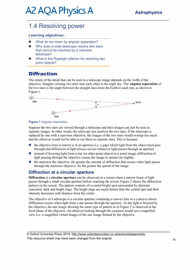
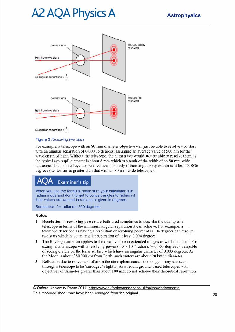
DiffractionThe extent of the detail that can be seen in a telescope image depends on the width of theobjective. Imagine viewing two stars near each other in the night sky. The angular separation of
the two stars is the angle between the straight lines from the Earth to each star, as shown inFigure 1.
Figure 1 Angular separation
Suppose the two stars are viewed through a telescope and their images can just be seen as
separate images. In other words, the telescope just resolves the two stars. If the telescope isreplaced by one with a narrower objective, the images of the two stars would overlap too much
and the observer would not be able to see them as separate stars. This is because:
the objective lens or mirror is in an aperture (i.e. a gap) which light from the object must passthrough and diffraction of light always occurs whenever light passes through an aperture
instead of focusing light from a star (or other point object) to a point image, diffraction oflight passing through the objective causes the image to spread out slightly.
the narrower the objective, the greater the amount of diffraction that occurs when light passesthrough the narrower objective. So the greater the spread of the image.
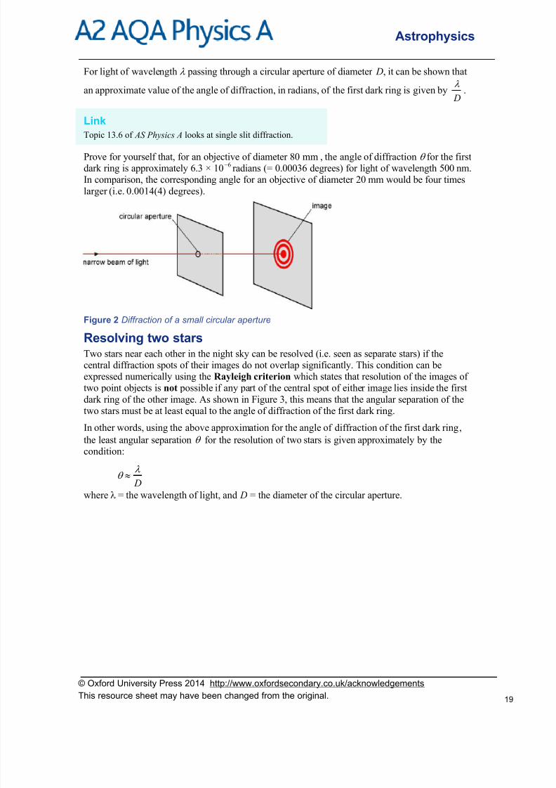
Diffraction at a circular apertureDiffraction at a circular aperture can be observed on a screen when a narrow beam of light
passes through a small circular aperture before reaching the screen. Figure 2 shows the diffraction
pattern on the screen. The pattern consists of a central bright spot surrounded by alternate
concentric dark and bright rings. The bright rings are much fainter than the central spot and theirintensity decreases with distance from the centre.
The objective of a telescope is a circular aperture containing a convex lens or a concave mirror.Diffraction occurs when light from a star passes through the aperture. As the light is focused bythe objective, the star image showing the same type of pattern as in Figure 2 is observed in thefocal plane of the objective. An observer looking through the eyepiece would see a magnified
view (i.e. a magnified virtual image) of the star image formed by the objective.
© Oxford University Press 2014 http://www.oxfordsecondary.co.uk/acknowledgements
This resource sheet may have been changed from the original. 18
8/9/2019 PhysicsA2 OptionAstrophysics Telescopes
http://slidepdf.com/reader/full/physicsa2-optionastrophysics-telescopes 19/27
Astrophysics
For light of wavelength passing through a circular aperture of diameter D, it can be shown that
an approximate value of the angle of diffraction, in radians, of the first dark ring is given by D
.
Link
Topic 13.6 of AS Physics A looks at single slit diffraction.
Prove for yourself that, for an objective of diameter 80 mm , the angle of diffraction for the firstdark ring is approximately 6.3 × 10⁻⁶ radians (= 0.00036 degrees) for light of wavelength 500 nm.In comparison, the corresponding angle for an objective of diameter 20 mm would be four times
larger (i.e. 0.0014(4) degrees).
Figure 2 Diffraction of a small circular aperture
Resolving two starsTwo stars near each other in the night sky can be resolved (i.e. seen as separate stars) if thecentral diffraction spots of their images do not overlap significantly. This condition can beexpressed numerically using the Rayleigh criterion which states that resolution of the images oftwo point objects is not possible if any part of the central spot of either image lies inside the first
dark ring of the other image. As shown in Figure 3, this means that the angular separation of the
two stars must be at least equal to the angle of diffraction of the first dark ring.In other words, using the above approximation for the angle of diffraction of the first dark ring,
the least angular separation for the resolution of two stars is given approximately by thecondition:
D
where = the wavelength of light, and D = the diameter of the circular aperture.
© Oxford University Press 2014 http://www.oxfordsecondary.co.uk/acknowledgements
This resource sheet may have been changed from the original. 19
8/9/2019 PhysicsA2 OptionAstrophysics Telescopes
http://slidepdf.com/reader/full/physicsa2-optionastrophysics-telescopes 20/27
Astrophysics
Figure 3 Resolving two stars
For example, a telescope with an 80 mm diameter objective will just be able to resolve two starswith an angular separation of 0.000 36 degrees, assuming an average value of 500 nm for thewavelength of light. Without the telescope, the human eye would not be able to resolve them as
the typical eye pupil diameter is about 8 mm which is a tenth of the width of an 80 mm widetelescope. The unaided eye can resolve two stars only if their angular separation is at least 0.0036
degrees (i.e. ten times greater than that with an 80 mm wide telescope).
When you use the formula, make sure your calculator is inradian mode and don’t forget to convert angles to radians iftheir values are wanted in radians or given in degrees.
Remember: 2 radians = 360 degrees.
Notes
1 Resolution or resolving power are both used sometimes to describe the quality of a
telescope in terms of the minimum angular separation it can achieve. For example, a
telescope described as having a resolution or resolving power of 0.004 degrees can resolvetwo stars which have an angular separation of at least 0.004 degrees.
2 The Rayleigh criterion applies to the detail visible in extended images as well as to stars. Forexample, a telescope with a resolving power of 5 × 10
−5radians (= 0.003 degrees) is capable
of seeing craters on the lunar surface which have an angular diameter of 0.003 degrees. Asthe Moon is about 380 000 km from Earth, such craters are about 20 km in diameter.
3 Refraction due to movement of air in the atmosphere causes the image of any star seenthrough a telescope to be ‘smudged’ slightly. As a result, ground-based telescopes with
objectives of diameter greater than about 100 mm do not achieve their theoretical resolution.
© Oxford University Press 2014 http://www.oxfordsecondary.co.uk/acknowledgements
This resource sheet may have been changed from the original. 20

8/9/2019 PhysicsA2 OptionAstrophysics Telescopes
http://slidepdf.com/reader/full/physicsa2-optionastrophysics-telescopes 21/27
Astrophysics
The stunning clarity of images from the Hubble Space Telescope is because the telescope hasan objective mirror of diameter 2.4 m and is above the atmosphere and therefore does not
suffer from atmospheric refraction. Hence it achieves its theoretical resolution which is about240 times greater than that of a 100
mm wide telescope.
How science works and application
The Hubble Space Telescope
Figure 4 A HST image of a cluster of galaxies
After it was first launched in 1990, HST images were found to be poor because of sphericalaberration in its primary mirror due to a manufacturing fault. This was corrected in 1993 when a
space shuttle mission was launched to enable astronauts to fit small secondary mirrors to
compensate exactly for the fault and give amazing images that have dramatically increased our
knowledge of space.
The Hubble Space Telescope detects images at wavelengths from 115 nm to about 1000 nm, thus
giving infrared, visible and ultraviolet images.
Summary questions
1 a What is the name for the physical phenomenon that causes the image formed by a lens or mirror of a
point object to be spread out?
b i Sketch the pattern of the image of a distant point object formed by a lens.
ii Describe how the pattern would differ if a wider lens of the same focal length had been used?
2 State and explain what is meant by the Rayleigh criterion for resolving two point objects using a
telescope.
3 Two stars have an angular separation of 8.0 × 10⁻⁶ rad.
a Assuming light from them has an average wavelength of 500 nm, calculate an approximate value for
the diameter of the objective of a telescope that can just resolve the two stars.
b Discuss how the image of the two stars would differ if they were viewed with a telescope with an
objective of twice the diameter and the same angular magnification.
4 The Hubble Space Telescope has an objective of diameter 2.4 m.
a Show that the theoretical resolution of the HST is 1.2 × 10 −5 degrees.
b Hence estimate the diameter of the smallest crater on the Moon that can be seen using the telescope.
Assume the wavelength of light is 500 nm.
Earth – Moon distance = 3.8 × 10⁸ m
© Oxford University Press 2014 http://www.oxfordsecondary.co.uk/acknowledgements
This resource sheet may have been changed from the original. 21

8/9/2019 PhysicsA2 OptionAstrophysics Telescopes
http://slidepdf.com/reader/full/physicsa2-optionastrophysics-telescopes 22/27
Astrophysics
1.5 Telescopes and technology
Learning objectives:
What is a charge-coupled device (CCD) and why
is it important in astronomy? How does a CCD work?
What are non-optical telescopes used for?
How do non-optical telescopes compare witheach other and with optical telescopes?
Charge-coupled devicesAstronomers have always used photographic film to capture images ever since photography wasfirst invented in the 19th century. However, the charge-coupled device invented in the late 20thcentury fitted to a telescope has dramatically extended the range of astronomical objects that can
be seen as well as providing images of stunning quality.
Figure 1 Using a CCD (a) A CCD in a telescope (b) A CCD image of a spiral galaxy
The CCD is an array of light-sensitive pixels which become charged when exposed to light. After being exposed to light for a pre-set time, the array is connected to an electronic circuit which
transfers the charge collected by each pixel in sequence to an output electrode connected to acapacitor. The voltage of the output electrode is ‘read out’ electronically then the capacitor isdischarged before the next pulse of charge is received. In this way, the output electrode produces
a stream of voltage pulses, each one of amplitude in proportion to the light energy received by anindividual pixel. Figure 2 shows part of an array of pixels.
© Oxford University Press 2014 http://www.oxfordsecondary.co.uk/acknowledgements
This resource sheet may have been changed from the original. 22

8/9/2019 PhysicsA2 OptionAstrophysics Telescopes
http://slidepdf.com/reader/full/physicsa2-optionastrophysics-telescopes 23/27
Astrophysics
Figure 2 Inside a CCD
Each pixel has three small rectangular metal electrodes (labelled A, B and C in Figure 2) whichare separated by a thin insulating layer of silicon dioxide from p-type silicon which is the light-sensitive material underneath. The electrodes are connected to three voltage supply ‘rails’.
The rectangular electrodes and the insulating layer are thin enough to allow light photons to
pass through and each liberate an individual electron in the light-sensitive materialunderneath.
When collecting charge, the central electrode in each pixel (labelled B in Figure 2) is held at
+10 V and the two outer electrodes at +2
V. This ensures the liberated electrons accumulate
under the central electrode.
After the pixels have collected charge for a certain time, the charge of each pixel is shifted
towards the output electrode via the adjacent pixels. This is achieved by altering the voltage
level of each electrode in a sequence of three-step cycles, as shown in Figure 2.The quantum efficiency of a pixel is the percentage of incident photons that liberate an electron.
About 70% of the photons incident on a pixel each liberates an electron. Therefore, the quantumefficiency of a pixel is about 70%. In comparison, the grains of a photographic film have aquantum efficiency of about 4% as only about 4 in every 100 incident photons contributes to thedarkening of each grain. So a CCD is much more efficient than a photographic film and hence itwill detect much fainter astronomical images than a film.
Further advantages of a CCD Its use in recording changes of an image. It can record a sequence of fast-changing
astronomical images which can be seen by the eye but could not be recorded on a photographic film.
Its wavelength sensitivity from less than 100 nm to 1100 nm is wider than that of the humaneye which is from about 350 nm to 650 nm. Hence it can be used with suitable filters to obtain
infrared images.
The quantum efficiency of a CCD is the same at about 70% from about 400 nm to 800 nm,reducing to zero below 100
nm and at 1100
nm.
However, CCDs for use in astronomy need to have a larger number of pixels in a small area andare therefore expensive compared with CCDs in most electronic cameras. More significantly,CCDs used in astronomy are often cooled to very low temperatures using liquid nitrogen
© Oxford University Press 2014 http://www.oxfordsecondary.co.uk/acknowledgements
This resource sheet may have been changed from the original. 23

8/9/2019 PhysicsA2 OptionAstrophysics Telescopes
http://slidepdf.com/reader/full/physicsa2-optionastrophysics-telescopes 24/27
Astrophysics
otherwise random emission of electrons causes a ‘dark’ current which does not depend on theintensity of light.
Radio telescopesSingle-dish radio telescopes each consist of a large parabolic dish with an aerial at the focal point
of the dish. A steerable dish can be directed at any astronomical source of radio waves in the sky.The atmosphere transmits radio waves in the wavelength range from about 0.001 m to about 10 m.When the dish is directed at an astronomical source that emits radio waves in the abovewavelength range, the waves reflect from the dish onto the aerial to produce a signal. The dish is
turned by motors to enable it to scan sources and to compensate for the Earth’s rotation.
Figure 3 A single-dish radio telescope
The amplitude of the signal is a measure of the intensity of the radio waves received by the dish.
The signal from the aerial is amplified and supplied to a computer for analysis and recording. Asthe dish scans across the source, the signal is used to map the intensity of the radio waves across
the source to give a ‘radio’ image of the source.
The dish surface usually consists of a wire mesh which is lighter than metal sheets and just as
effective in terms of reflection, provided the mesh spacing is less than about20
, where is the
wavelength of the radio waves.
The dish diameter, D, determines
the collecting area of the dish (=4
1 D2)
the resolving power of the telescope (= D
)
The Lovell radio telescope at Jodrell Bank in Cheshire has a 76 m steerable dish which gives a
resolution of 0.2 degree for 21 cm wavelength radio waves. In comparison, the Arecibo radiotelescope in Puerto Rica is a 300 m fixed concave dish set in a natural bowl. As it is four times
wider than the Lovell telescope, it can therefore resolve radio images to about 0.05 degrees
(=4
1 of 0.2) and detect radio source 16 times fainter (as it collects 16 times as much radio
© Oxford University Press 2014 http://www.oxfordsecondary.co.uk/acknowledgements
This resource sheet may have been changed from the original. 24

8/9/2019 PhysicsA2 OptionAstrophysics Telescopes
http://slidepdf.com/reader/full/physicsa2-optionastrophysics-telescopes 25/27
Astrophysics
energy per second than the Lovell telescope does). However, the Arecibo telescope can onlydetect radio sources when they are close to its principal axis.
Uses of radio telescopes
Locating and studying strong radio sources in the sky
The Sun, Jupiter and the Milky Way are all strong sources of radio waves. Some galaxies are alsorelatively strong emitters of radio waves. Such galaxies are usually elliptical or spherical withoutspiral arms. Many radio galaxies are found near the centre of clusters of galaxies and their opticalimages often show evidence of violent events such as two galaxies merging or colliding or agalaxy exploding or emitting immensely powerful jets of matter.
Mapping the Milky Way galaxyHydrogen atoms in dust clouds in space emit radio waves of wavelength 21 cm. These are emitted
when the electron in a hydrogen atom flips over so its spin changes from being in the samedirection as the proton’s spin to a lower energy level in the opposite direction . The Milky Way is
a spiral galaxy with the Sun in an outer spiral arm. Dust clouds in the spiral arms prevent us fromseeing stars and other radio sources, such as hot gas behind the dust clouds, as dust absorbs light.However, radio waves are not absorbed by dust so radio telescopes are used to map the Milky
Way.
Link
Electromagnetic waves were looked at in Topic 1.3 of
AS Physics A.
Infrared telescopesInfrared telescopes have a large concave reflector which focuses infrared radiation onto aninfrared detector at the focal point of the reflector. Objects in space such as planets that are nothot enough to emit light emit infrared radiation. In addition, dust clouds in space emit infrared
radiation. Infrared telescopes can therefore provide images from objects in space that cannot beseen using optical telescopes.
Ground-based infrared telescopesA ground-based infrared telescope needs to be cooled to stop infrared radiation from its ownsurface swamping infrared radiation from space. Water vapour in the atmosphere absorbs infrared
radiation, so an infrared telescope needs to be sited where the atmosphere is as dry as possibleand as high as possible. The 3 m diameter infrared telescope on a mountain in Hawaii is locatedthere because the atmosphere is very dry and the water vapour that is present has less effect thanif the telescope was at a lower level.
Infrared telescopes on satellites
An infrared telescope on a satellite in orbit above the Earth is not affected by water vapour.However, the telescope still needs to be cooled to a few degrees above absolute zero to be able todetect infrared radiation from weak infrared sources.
IRAS, the first infrared astronomical satellite, launched in 1978, discovered bands of dust in thesolar system and dust around nearby stars. It carried a 60
cm wide infrared telescope fitted with a
detector capable of detecting infrared wavelengths from 0.01 mm to about 1 mm.
© Oxford University Press 2014 http://www.oxfordsecondary.co.uk/acknowledgements
This resource sheet may have been changed from the original. 25

8/9/2019 PhysicsA2 OptionAstrophysics Telescopes
http://slidepdf.com/reader/full/physicsa2-optionastrophysics-telescopes 26/27
Astrophysics
The Hubble Space Telescope with its objective at 2.4 m wide is capable of detecting infraredwavelengths from 700 nm to about 1000 nm (= 0.001 mm). It can form images of ‘warm’ objects
such as dying stars and planets in other solar systems that emit thermal radiation but not light.
Ultraviolet telescopes
Ultraviolet (UV) telescopes must be carried on satellites because UV radiation is absorbed by theEarth’s atmosphere. As UV radiation is also absorbed by glass, a UV telescope uses mirrors tofocus incoming UV radiation onto a UV detector. UV radiation is emitted by atoms at hightemperatures, so UV telescopes are used to map hot gas clouds near stars and to study hot objects
in space such as glowing comets, supernova and quasars. Comparing a UV image of an objectwith an optical or infrared image gives useful information about hot spots in the object.
The International Ultraviolet Explorer (IEU) launched in 1978 carried a 0.45 m wideCassegrain telescope with a UV detector instead of an eyepiece in its focal plane.
The Hubble Space Telescope uses a CCD to detect images at wavelengths from 115 nm to
about 1000 nm, giving ultraviolet images as well as visible and infrared images according tothe filters used over the CCD.
The XMM-Newton space observatory, launched in 1999 and still in operation, carries a 30
cmwide modified Cassegrain reflector fitted with a detector with a wavelength range from170 nm to 650 nm. So, it can give ultraviolet as well as optical images.
Figure 4 A combined UV and optical image of the galaxy M82 galaxy (UV in blue).
X-ray and gamma-ray telescopesThey need to be carried on satellites as the Earth’s atmosphere absorbs X-rays and gamma rays.
Discoveries using such telescopes include: X-ray pulsars, stars that emit X-ray beams that sweep round the sky as they spin
X-ray and gamma-ray ‘bursters’ billions of light years away which emit bursts of gammarays.
X-ray telescopes work by reflecting X-rays off highly- polished metal plates at ‘grazing’ incidenceonto a suitable detector. Gamma ray telescopes work by detecting gamma photons as they pass
through a detector containing layers of ‘pixels’, triggering a signal in each pixel it passes throughit. The direction of each incident gamma photon can be determined from the signals. The
© Oxford University Press 2014 http://www.oxfordsecondary.co.uk/acknowledgements
This resource sheet may have been changed from the original. 26
8/9/2019 PhysicsA2 OptionAstrophysics Telescopes
http://slidepdf.com/reader/full/physicsa2-optionastrophysics-telescopes 27/27
Astrophysics
International Gamma Ray Astrophysics Laboratory (INTEGRAL) launched in 2002 is being usedto study supernova, gamma ray bursts and black holes. As gamma rays and X-rays are very short
wavelength, diffraction is insignificant and image resolution is determined by the pixelseparation.
Summary questions
The table below is an incomplete comparison of different types of astronomical telescopes.
Type Location Wavelengthrange
Resolution(degrees)
Key advantages Major disadvantages
optical ground orsatellite
350 –650 nm 10
− for HST gives very detailed
images,can detect distantgalaxies
ground telescopessuffer fromatmospheric refraction
radio ground 1 mm to 10
m 0.2 for
Lovellradio waves passthrough dust inspace and throughthe atmosphere
large, supportingstructure needed for asteerable dish.
infrared can detect warmobjects that do notemit light,
can detect dustclouds in space
mirror needs to becooled
ultraviolet must be above theEarth’s atmospheree.g. on a satellite
X andgamma
0.2 forINTEGRAL
must be above theEarth’s atmospheree.g. on a satellite
1 Copy this table and use the information in this topic to complete columns 2 and 3.
2 a Use the information in the previous pages to estimate the resolution in degrees of:
i HST at a wavelength of 0.001 mm
ii XMM-Newton at a wavelength of 170 nm
b Use your estimates to complete column 4 of your table.3 Complete column 5 by giving two key advantages of:
a UV telescopes
b X-ray and gamma ray telescopes.
4 The collecting power of a telescope is a measure of how much energy per second it collects. This
depends on the area of its objective as well as the power per unit area (intensity) of the incident
radiation.
a For the same incident power per unit area, list the following telescopes in order of their collecting
power:
Hubble Space Telescope (2.4 m in diameter)
INTEGRAL (0.60 m diameter)
IRAS (0.60 m diameter)
Lovell telescope (76 m diameter)
XMM-Newton (0.30 m diameter)
b The Lovell radio telescope is linked to other radio telescopes in England so they act together as an
effective radio telescope of much greater width. Discuss without calculations how the resolving
power and the collecting power of the linked system compare with that of the Lovell telescope on its
own.