Embed Size (px)
DESCRIPTION
.
Citation preview

X-ray Circuits
Student names: Atheer Al-Subaie
Malak Al-Ahmari Maged Al-ghanem


After we finished we should know ..
•The basic x-ray circuit. •What’s the functions for each components in x-ray circuit. •Explain the operational of components.
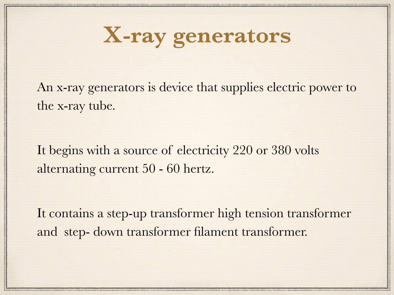
X-ray generators
An x-ray generators is device that supplies electric power to the x-ray tube.
It begins with a source of electricity 220 or 380 volts alternating current 50 - 60 hertz.
It contains a step-up transformer high tension transformer and step- down transformer filament transformer.

Electricity generation
* It is the process of obtaining electricity from other sources of energy through the use of a generator.
To convert mechanical energy into electrical energy. Conversion procedures are based on the relationship between
magnetism and electricity.

Electricity transportation
Transformer allows electricity to move efficiently over long distances
The electricity transmission voltage (high pressure) is the best way to do that (the greater the effort, the less loss), but the high voltage can not be used homes. Therefore the electricity effort is raise then electricity transmission through the high-voltage lines are then work to reduce the effort in the sub-stations to
supply adequate electric-powered home DC power is more efficient for long distance, high voltage
electricity transmission Balencih because it has less energy intransport.

BASIC X-RAY CIRCUIT
• When combined the main circuit with filament circuit it'll form the complete basic x-ray circuit that will produce x-rays.

Main X-ray Circuit
Two divisions to the main x-ray circuit: – Primary or control console section • Incoming current• Exposure switch • Autotransformer• Primary winding of the step-up transformer – Secondary or high voltage section • Secondary step-up transformer• Full-wave rectification circuits • Wiring leading to & from the x-ray tube

Main X-ray Circuit
Primary Secondary

Filament X-ray Circuit
• mA Selector – is a Rheostat (variable resistor) – Adjusts resistance and is represented by the mA stations on the control panel. • Filament step-down transformer – Responsible for changing amps into milliamps.

X-ray machine circuits
It’s comprise three main components:
1. A circuit for heating the filament.
2. A circuit for applying a large potential difference (high voltage) between cathode and anode to accelerate electrons.
3. A timing device to control the length of exposure.

1. The filament circuit • The tungsten filament at the cathode is the source of electrons used to
produce x-rays.
• The number of electrons produced at the tungsten filament is dependent upon the temperature of the filament.
• A tungsten filament needs to be heated to at least 2200°C to emit useful numbers of electrons.
• Electrons are produced by thermionic emission.
•When a metal is heated its atoms absorb energy which allows some electrons to move a small distance from the surface of the metal.
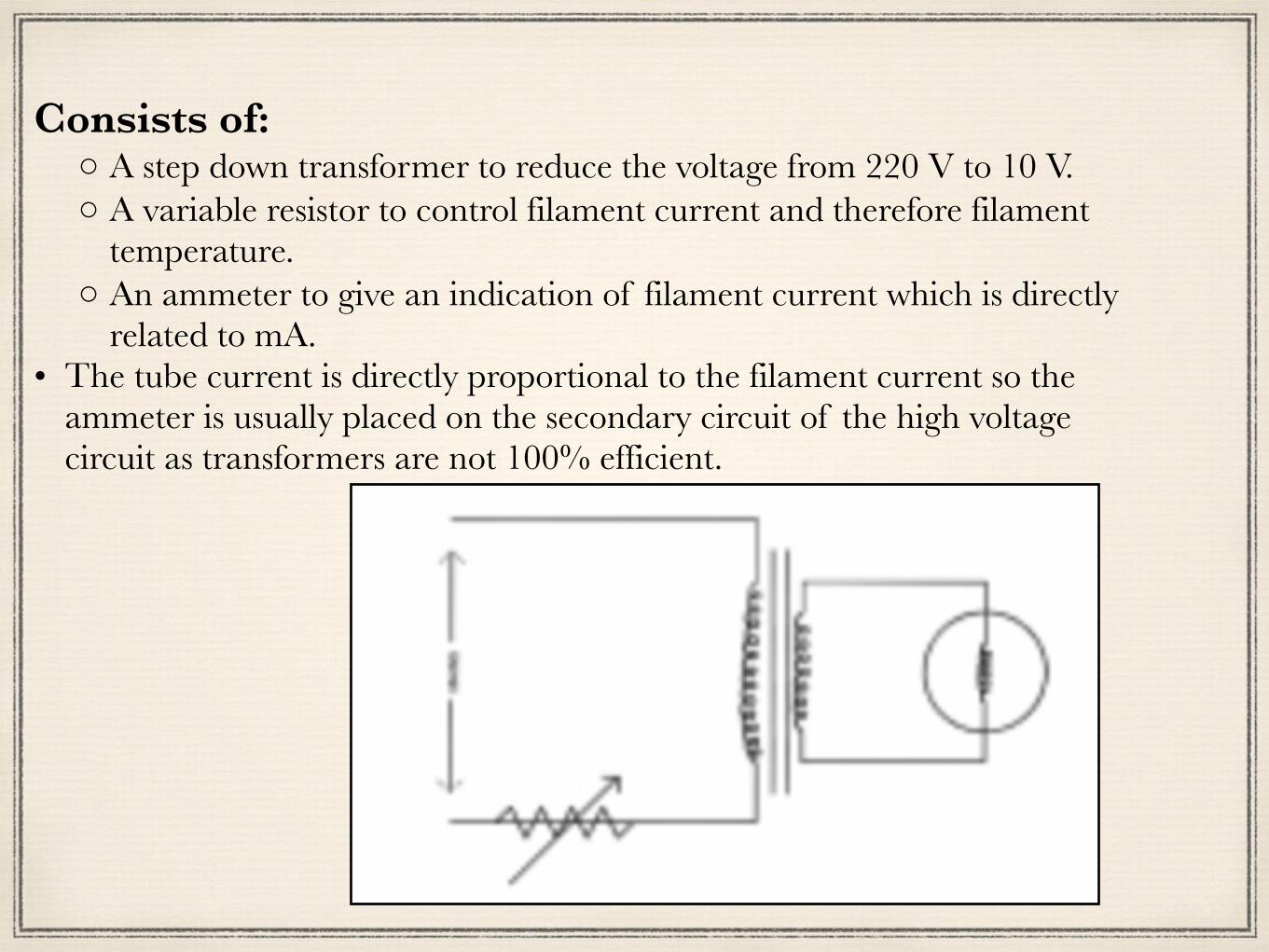
Consists of: ◦A step down transformer to reduce the voltage from 220 V to 10 V. ◦A variable resistor to control filament current and therefore filament
temperature. ◦An ammeter to give an indication of filament current which is directly
related to mA. • The tube current is directly proportional to the filament current so the
ammeter is usually placed on the secondary circuit of the high voltage circuit as transformers are not 100% efficient.
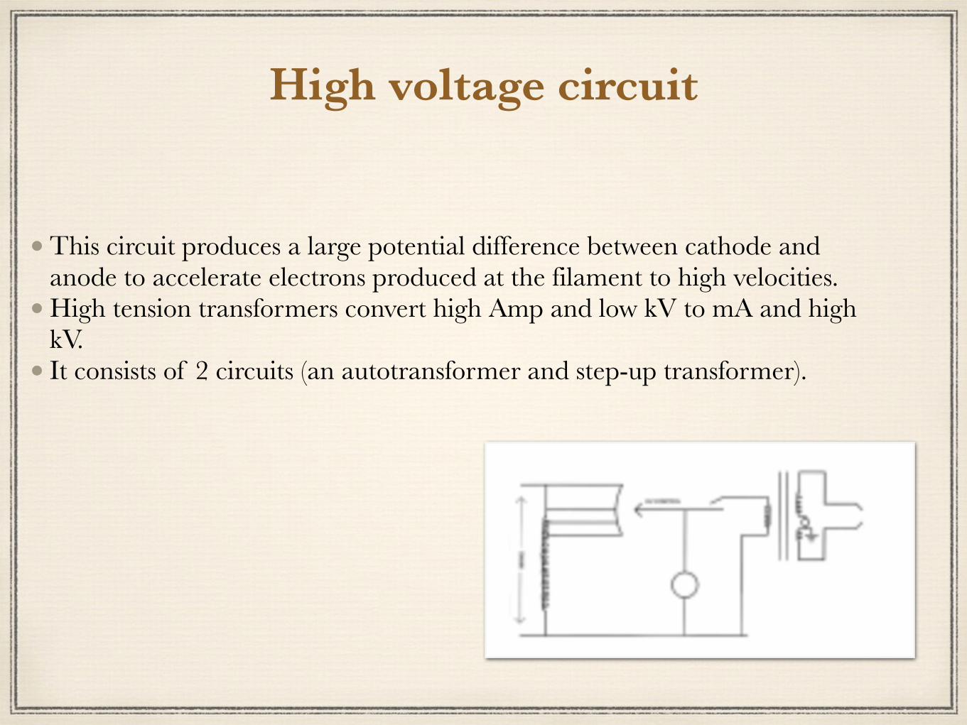
High voltage circuit
• This circuit produces a large potential difference between cathode and anode to accelerate electrons produced at the filament to high velocities.
• High tension transformers convert high Amp and low kV to mA and high kV.
• It consists of 2 circuits (an autotransformer and step-up transformer).

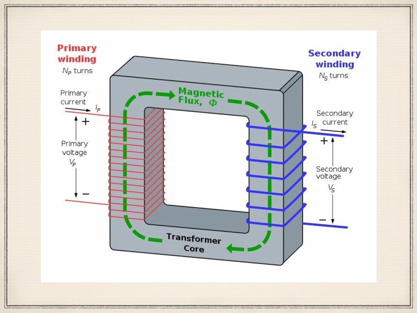
Transformer
It’s a static machine used for transforming power from one circuit to another without changing frequency.

Transformer
• Mains electricity is 240 V and has to be modified to produce a high voltage across the x-ray tube head and low voltage to heat the filament.
Transformers comprise two coils of wire wound around an iron core
• When current flows through one coil (primary) a magnetic field is generated which induces a current to flow in the secondary wire coil.
• The ratio of the incoming voltage to outgoing kilovolts is proportional to the number of turns on both the primary and secondary side (Vp/Vs = Tp/Ts).
• If the number of turns in the secondary coil is > than the number in the primary the voltage is increased.
• Step-up transformer has many more turns on the secondary coil than the primary coil.
16
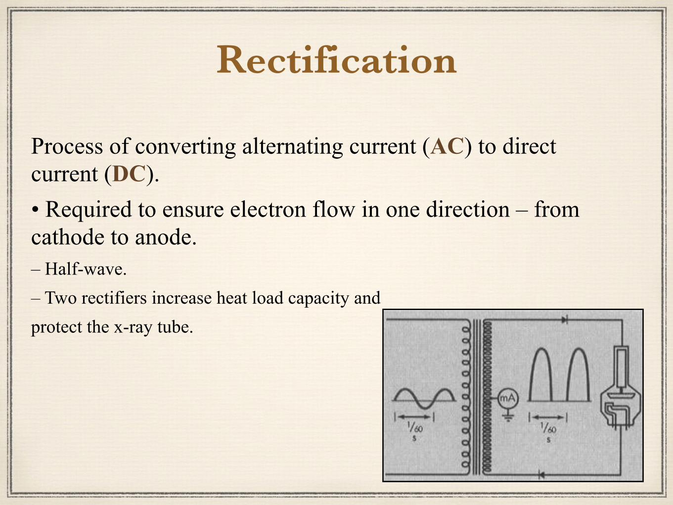
Rectification
Process of converting alternating current (AC) to direct current (DC). • Required to ensure electron flow in one direction – from cathode to anode. – Half-wave.– Two rectifiers increase heat load capacity and protect the x-ray tube.

Rectification
– Full-wave – Four rectifiers create a routing system sending electrons through the x-ray tube the same way every time, in effect creating DC.

Characteristics of Incoming Line Power
•The usual voltage taken by the equipment is 210-220v.
•May need an additional transformer to stabilize incoming voltage.

Characteristics of Incoming Line Power
Phasing: – Single-phase– Three-phase, six pulse– Three-phase, twelve pulse * High Frequency
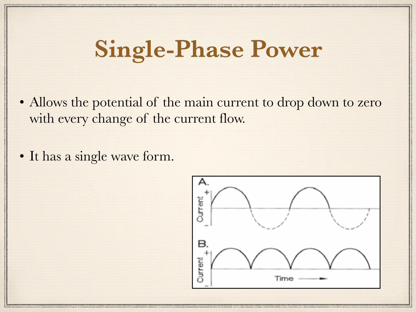
Single-Phase Power
•Allows the potential of the main current to drop down to zero with every change of the current flow.
• It has a single wave form.

Three-Phase Power
Has three waves of power flowing at evenly spaced intervals from each other: – One wave is starting before the previous wave is depleted
– The overall waveform never reaches zero
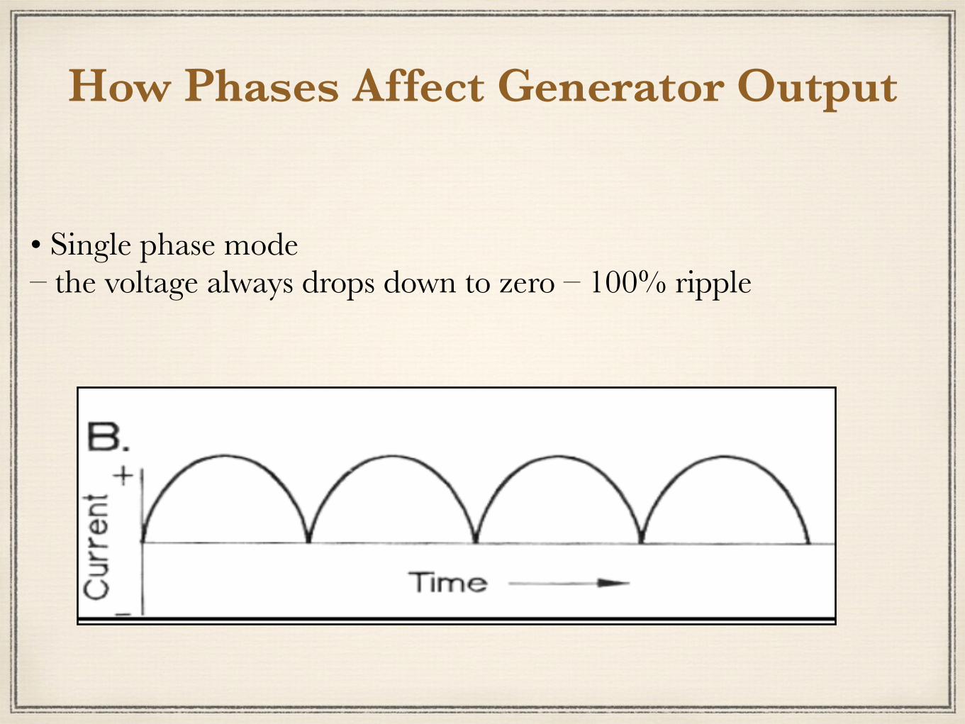
How Phases Affect Generator Output
• Single phase mode– the voltage always drops down to zero – 100% ripple

How Phases Affect Generator Output • Three phase: – Individual voltages drop to zero but there is always an overlap of wave pulses. – When wave pulses are rectified, the average value never drops to zero. •Makes x-ray production more efficient.
•Easier on the equipment.
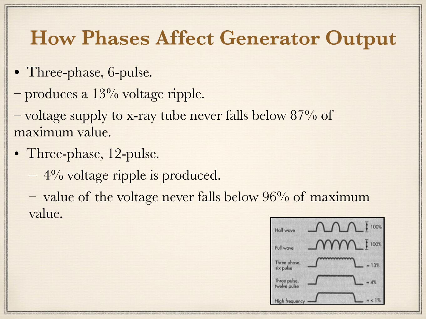
How Phases Affect Generator Output • Three-phase, 6-pulse. – produces a 13% voltage ripple. – voltage supply to x-ray tube never falls below 87% of maximum value. • Three-phase, 12-pulse. – 4% voltage ripple is produced. – value of the voltage never falls below 96% of maximum
value.
How Phases Affect Generator Output
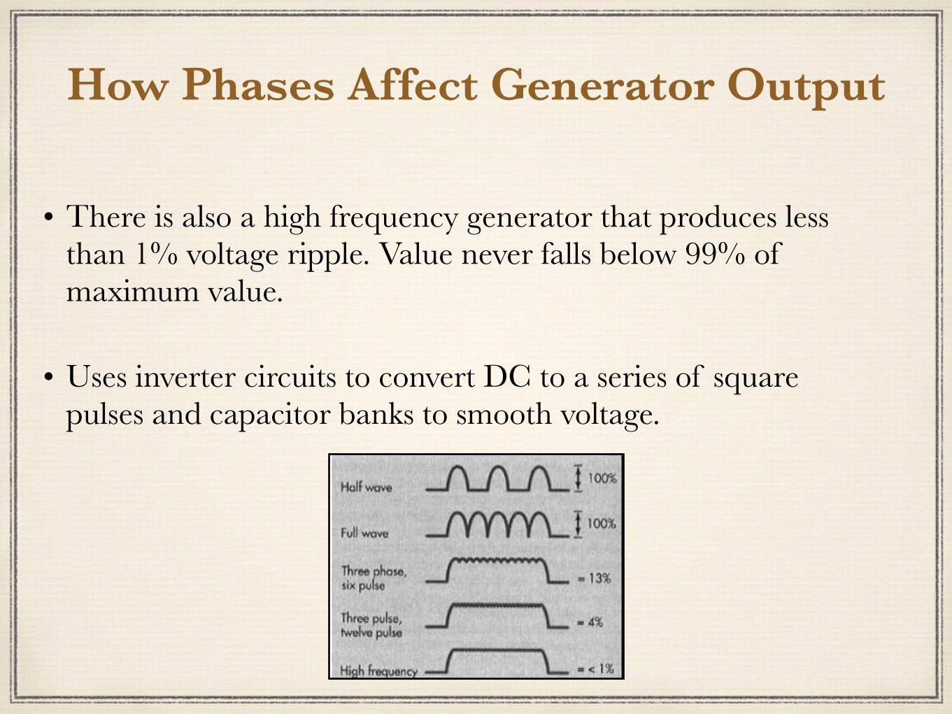
•There is also a high frequency generator that produces less than 1% voltage ripple. Value never falls below 99% of maximum value.
•Uses inverter circuits to convert DC to a series of square pulses and capacitor banks to smooth voltage.

Capacitor Discharge Mobile Units •A capacitor builds up a charge when the circuit is closed
(when exposure button is pushed).
•When pre-selected charge is reached, the capacitor completes the circuit & sends the charge to the x-ray tube.
•Disadvantage - x-ray production falls off throughout exposure (end kV is approx. 1 kV per mAs lower than starting kVp).

Thank you for listening


![Physics of Living Systems Arun Paramekanti Associate ...arunp/Teaching/... · Dorothy Hodgkin Francis Crick Physics Tools [X-ray diffraction] Applied X-ray crystallography to study](https://img.pdfslide.us/doc/110x75/5f7b9f18a548296c821d4c1c/physics-of-living-systems-arun-paramekanti-associate-arunpteaching-dorothy.jpg)