Embed Size (px)
Citation preview

(1)Title
Physics of High Pressure Helicon Plasma
and Effect of Wavenumber Spectrum
Interdisciplinary Graduate School of Engineering Sciences, Kyushu Univeristy, Japan Shunjiro SHINOHARA
Scientific Center Institute for Nuclear Research, Kiev, Ukraine Konstantin SHAMRAI
1. Introduction
� High Density Plasma Source cf. Plasma Application Studies � Study on Helicon Source (Physics)
Critical Issues: Plasma Generation Mechanism & Application Comparison: Experiment & Computation Future Plan: Large & Small Volume Plasmas
2. Experimental Setup + Theory
� Large Diameter Plasma Device � Antenna Structure � Theoretical Model (TG Wave: Mode Conversion)
3. Results
� Good Agreement between Experimental Results and Computed Ones Based on H-TG Model
Antenna Loading , Power Absorption, Wave Structures TE-H Model: Poor Agreement
� Future Plan Small & Large Plasmas
3. Summary

(2)Intro
Introduction � Importance of High Density Plasma Source Plasma Processing, Accelerator, Laser, Confinement Devices
…. � Study on Helicon Source (Physics) e.g., Diameter 5 - 45 cm [1-5], Change of Antenna Spectra [6-9]
� � Critical Issues Plasma Generation Mechanism, Density Jump, Control of
Discharge and Optimization ..... Application �
� Control of Discharge Regime and Wave Structures
Comparison: Experiment & Computation 1) Antenna Spectra (2 Loops, Current Direction) 2) Magnetic Field (0 - 1000 G) 3) RF Input Power (� 3 kW) 4) Pressure (Ar : 6, 51 mTorr) � Antenna Loading & Density Jump, Wave Structures Power Absorption (Bulk & Edge) cf. TG Wave (Mode Conversion) � Future Plan (Large & Small Volume)
References [1] S. Shinohara, Y. Miyauchi and Y. Kawai, Plasma Phys. Control. Fusion 37
(1995) 1015. [2] S. Shinohara, Y. Miyauchi and Y. Kawai, Jpn. J. Appl. Phys. 35 (1996) L731. [3] S. Shinohara, S. Takechi and Y. Kawai, Jpn. J. Appl. Phys. 35 (1996) 4503. [4] S. Shinohara, Jpn. J. Appl. Phys. 36 (1997) 4695. [5] S. Shinohara, S. Takechi, N. Kaneda and Y. Kawai, Plasma Phys. Control.
Fusion 39 (1997) 1479. [6] S. Shinohara, N. Kaneda and Y. Kawai, Thin Solid Films 316 (1998) 139. [7] S. Shinohara and K. Yonekura, Plasma Phys. Control. Fusion 42 (2000) 41. [8] S. Shinohara and K. P. Shamrai, ibid. 42 (2000) 865. [9] K. P. Shamrai and S. Shinohara, Phys. Plasmas 8 (2001) 4659.

Schematic View of Experimental Device
Axial Magnetic Field Coils
To Pump
170 cm
Ar Gas B
Magnetic Probe
80 cm
Magnetic ProbeLangmuir Probe
Loop Antenna
Microwave Interferometer
z0
20 cm
Chamber(Yoko)M

Schematic View of Antenna Structures
(a) Parallel Current (b) Anti-Parallel Current
d = 1 cm
L = 2 cm
0.0
0.2
0.4
0.6
0.8
1.0
0.0 0.5 1.0 1.5 2.0 2.5 3.0
kz (cm-1 )
Parallel
Anti-Parallel
Power Spectra of Antenna Wavenumber j (kz)2
(d = 1 cm, L = 2 cm)
AntennaMM

(5)thmodelM.doc
THEORETICAL MODEL H-TG Model cf. Ez = 0 (TE-H Model)
Maxwell Equations c∇×E = iωB
c∇×B = − iωD + 4πiaδ(r − r0)
Boundary and Joining Conditions Et(z = R, L) = 0 { }Et 0rr = = 0, { }Bt 0rr = = 4πia/c
Antenna Current and Fields ia = Σ ik zsinkzz
kz = lzπ/(R−L), lz = 1,2 … lzmax E = Σ (E⊥sinkzz + z Ezcoskzz)
B = Σ (B⊥coskzz + z Bzsinkzz)
Permittivity Tensor K1 = 1 − ωγω
γω2ce
2e
2e
2pe
− −
γω
ω
i2
2pi ,
K2 = )( 2
ce2e
2ce
2pe
ωγωω
ωω
− , K3 = 1 +
)()/(i1)(11
ee2De
2 ξγωνξ
w
w
rk z −−
Collisions and Landau Damping γe,i= 1+i(νe,i/ω), νe= νen+νei , ξ = ωγe/kzvTe
Plasma Load Impedance Zp = − [4π2r0(R−L)/c] Σ |ikz/Ia|2�θ(r = r0)
Plasma Density Profile n (r) = n0 – (n0 – nedge) ( r / r0 )2 _______________________________________________________________________________________
Ref.: K. P. Shamrai, V. P. Pavlenko and V. B. Taranov: Plasma Phys. Control. Fusion 39 (1997) 505. K. P. Shamrai and S. Shinohara: Phys. Plasmas 8 (2001) 4659.
ra
Ia2
za
CFCFm=0 antenna
Double
Rd
b
PlasmaVacuum
Ia1
r0 zL

Fig.1(a,b)(51mT,para/anti,H)M
109
1010
1011
1012
1013
1014 1000 G
650 G500 G300 G
50 G30 G
100 G
(a) Parallel
109
1010
1011
1012
1013
1014
10 100 1000
Pin (W)
1000 G
650 G
500 G 300 G
100 G 50 G30 G
(b) Anti-Parallel
[ Electron Density as a Function of Input Power ]P = 51 mTorr
Lower Wave Number Spectrum Part and/or Lower Magnetic Field is Necessary for Obtaining High Density Plasma with Low RF Power
(Experiment)

2Loop(AP).G4M3m
[ Plasma Density ne as a Function of Pressure P ]
Lower Wavenumber Spectrum Part is Necessary
for Plasma Initiation in Lower Pressure Range
10 10
10 11
10 12
10 13
10 14
0.001 0.01 0.1
P (Torr)
L = 1.5 cm
2 cm
4 cm7.5 cm
15.5 cm
OscillationO (10 12 cm -3 )
L: Distance between Two Loop Antennae with Opposite Current Directions
(8)PoP_colorM(13,18,20) 13
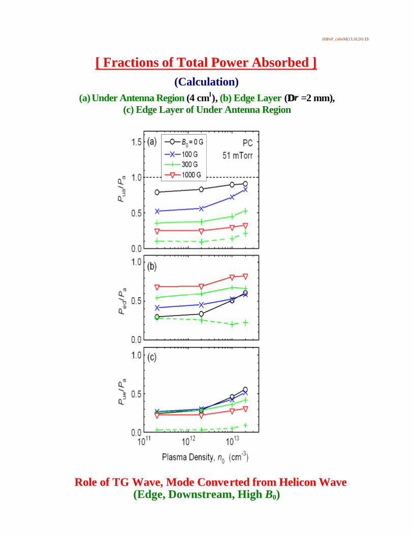
[ Fractions of Total Power Absorbed ] (Calculation)
(a) Under Antenna Region (4 cm
l ), (b) Edge Layer (∆∆r =2 mm),
(c) Edge Layer of Under Antenna Region
Role of TG Wave, Mode Converted from Helicon Wave (Edge, Downstream, High B0)

(9)PoP_colorM(13,18,20) 18
[ Comparison: Measured and Computed Resistances ]
H-TG Model: Good Agreement
(ICP) nedge = 0.5 (PC)
1.0 (AC)
----------------------------- nedge = 0.5 (PC)
1.0 (AC)
nedge = 0.2 (PC)

(10)PoP_colorM(13,18,20) 20
[ Comparison: Measured and Computed B z Profiles ]
H-TG Model: Good Agreement
PAr = 51 mTorr, B0 = 300 G
Before Density Jump After Density Jump

(11)PoP_f11M.doc
[ Power Absorption Profiles (mW/cm3) in log Scale ] PAr = 6 mTorr, ne = 2 × 1012 cm-3, B0 = 100 G, Parallel Currents (1 A each)
(Calculation)
(a) H-TG Model Uniform Plasma
(b) H-TG Model Non-Uniform Plasma (nedge = 0) -----------------
(c) TE-H Model
Uniform Plasma
- 4 0
- 3 0
- 2 0
- 1 0
0
zHc mL0.5
11.5
22.5
rHc mL0
1
- 4 0
- 3 0
- 2 0
- 1 0
0
zHc mL0
1
- 4 0
- 3 0
- 2 0
- 1 0
0
zHc mL0.5
11.5
22.5
rHc mL0
1
- 4 0
- 3 0
- 2 0
- 1 0
0
zHc mL0
1
- 4 0
- 3 0
- 2 0
- 1 0
0
z Hc mL0 . 5
11 . 5
22 . 5
rHc mL- 2
- 1
0
- 4 0
- 3 0
- 2 0
- 1 0
0
z Hc mL- 2
- 1
0

(12)Large Diameter
[ Large Volume Plasma Production by Helicons ]
Sh [ Kyushu Univ. ]
Large Diameter Plasma: 45 cmφφ, 170 cml, 2 kG 3 - 15 MHz, 5 kW, Spiral Antenna (4 Turns, 18 cmφφ)
Cusp, Divergent & Convergent Fields (Uniformity, Wave Studies)
(Present: BaO Discharge) [ Institute of Space & Astronautical Science ]
Device for High Density Plasma Production: 75 cmφφ, 490 cml, 2 kG
Plan: 1.8 - 30 MHz, 1 kW (or more), Spiral Antenna (5 Turns, 22 cmφφ) Production of Target Plasma (Space and Basic Fields), Profile Control Plasma Propulsion (cf. Muses C (Asteroid): 2002~), Wave Studies
------------------------------ cf. UCLA (Wave Studies) ‘LAPD’ by Gekelman (80 cmφφ�1,800 cml )
Large Linear Plasma Device by Stenzel (150 cmφφ�250 cml )

(13)SMALL _M0.doc
[ Small Source ] Initial Data
Single-Loop m = 0 Antenna in the Midplane
Calculation: L = 4 cm; r0 = 2 cm; ra = 2.2 cm; Te = 4 eV; f = 100 MHz (f / fce = 0.36 for B0 = 100 G)
(a) (ICP)
---------------------------------------
(b) (c)
[ Plasma Loading Resistance vs. Plasma Density ]

(14)Concl
Summary Comparison between Experiment and Computation Future Plan: Large and Small Sources
High Pressure (6, 51 mTorr) Antenna Spectra (2 Loops�Same & Opposite Directions)
f = 7 MHz, B = 0 - 1000 G cf. 4 Loops
Mode Conversion (Helicon & TG Waves) Bulk & Edge
(Results� � Good Agreements were found Between Experiment and
Computation Results (H-TG Model) on Antenna Loading, Density Jump and Wave Structures under Various Parameters.
High Pressure, High Field, Opposite Current Directions � High Threshold Power for Density Jump
� With the Increase in the Magnetic Field, Density and Edge Density Ratio, Larger Antenna Loading and Enhanced Edge Absorption (TG Wave, z Direction), and Absorption Spectra with Higher kz Component were Found (Computation).
� Absorption near Antenna Region Increased with Density, but Decreased with the Magnetic Field (Computation).
� Effects of Pressure and Antenna Spectra were also Investigated (Computation).
� The H-TG Model is Better to Explain Obtained Results than the
TE-H Model.
Future Plan
� Studies on Large & Small Diameter Plasmas for Basic and Plasma Propulsion Studies were Discussed Shortly.