Embed Size (px)
Citation preview
Inr J. Radialron Oncology Bmi. Phye, Vol. 18, pp. 941-949 0360.3016/90 $3.00 + .OO Printed in the U.S.A. All rights reserved. Copyright 0 1990 Pergamon Press plc
??Technical Innovations and Notes
PHYSICS OF GAMMA KNIFE APPROACH ON CONVERGENT BEAMS IN STEREOTACTIC RADIOSURGERY
ANDREW Wu, PH.D.,* G. LINDNER, M.S., * A. H. MAITZ, M.S.,* A. M. KALEND, PH.D.,* L. D. LUNSFORD, M.D.,+ J. C. FLICKINGER, M.D.* AND W. D. BLOOMER, M.D.*
University of Pittsburgh School of Medicine, Joint Radiation Oncology Center and Pittsburgh Cancer Institute, Pittsburgh, PA 152 13
The Presbyterian-University Hospital of Pittsburgh installed the first clinically designated Leksell gamma knife in the U.S. in August 1987. Gamma knife radiosurgery involves stereotactic target localization with the Leksell frame and subsequent closed-skull single-treatment session irradiation of a lesion with multiple highly focused gamma ray beams produced from @‘Co sources. The hemispherical array of sources, the large number of small- diameter beams, and the steep dose gradients surrounding a targeted lesion make physical characterization of the radiation field complex. This paper describes the physical features and the operation of the gamma knife as well as the calibration procedures of the very small, well-collimated beams. The results of studies using in-phantom ion chamber, diode, film, and lithium fluoride thermoluminescent dosimetry were all in close agreement. Both single- beam and multiple-beam dose profiles were measured and reported for the interchangeable helmets, which have 4-, 8-, 14-, and l&mm-diameter collimators. We also describe the dose calculation and treatment planning algorithm in the treatment planning system. Measurements of the accuracy of mechanical and radiation alignment are also performed and discussed.
Radiosurgery, Stereotactic frame, @‘Co, Dosimetry.
INTRODUCTION
In 195 1, Swedish neurosurgeon Lars Leksell of the Ka- rolinska Institute in Stockholm proposed “stereotactic ra- diosurgery”, the use of external radiation in conjunction with a stereotactic guidance device to precisely locate and destroy inaccessible targets within the brain (16). Much of the early work in stereotactic radiosurgery, by Leksell and physicist Borje Larsson from the Gustaf Werner In- stitute, University of Uppsala, Sweden, was with proton beams generated by a cyclotron ( 14, 17). However, only a few institutions in the world have a cyclotron in a clinical setting (8, 1 l- 13). Because of the inefficiency, complexity, and expense of the technique, an alternative source of radiation was sought. In 1968, the first gamma knife using 6oCo was installed at the Karolinska Institute (18). This prototype was designed to produce slit-like radiation le- sions for functional neurosurgical procedures to treat pain, movement disorders, or behavioral disorders that did not respond to conventional treatment.
The success of this first unit led to the construction of a second device, which has been used at the Karolinska
Institute since 1975. Containing 179 6oCo sources, this second gamma knife unit was designed to produce spher- ical lesions to treat brain tumors and intracranial arterio- venous malformations (AVM). In the 1980s the third and fourth units (with 201 (j°Co sources) were installed in Buenos Aires, Argentina, and Sheffield, England (27). The fifth gamma knife was installed at the Presbyterian University Hospital of Pittsburgh in 1987.
The Pittsburgh unit is the first gamma knife to produce an l&mm-diameter beam in addition to the 4-, 8-, and 14-mm beams available on the first four units. Alternative systems also have been developed for stereotactic radiation therapy using linear accelerators (20, 21). Dosimetry measurements for small radiation fields for X ray of var- ious energies produced by linear accelerators have been studied (2, 7, 10, 23).
Stereotactic radiosurgery may be the only feasible treatment for some patients with surgically unresectable brain lesions, for those with residual lesions after at- tempted resection, or for patients whose general health or advanced age precludes conventional intracranial sur- gery. Review of the literature reveals a wide variety of
* Department of Radiation Oncology. + Department of Neurosurgery. Reprint requests to: A. Wu, Ph.D., Department of Radiation
Oncology, Presbyterian-University Hospital, 230 Lothrop Street, Pittsburgh, PA 152 13.
Acknowledgements-This work was supported in part by the Claude Worthington Benedum Foundation.
Accepted for publication 9 August 1989.
941
942 I. J. Radiation Oncology 0 Biology 0 Physics April 1990, Volume 18, Number 4
Fig. 1. A picture of the gamma knife unit. It shows the outside of the radiation unit with shielding door closed, a collimator helmet, and the patient treatment table.
disorders treated with this technique (3,4, 12, 15, 19,25). Steiner et al. report angiographic obliteration of intracra- nial AVM in 37% of their patients 1 year after treatment, in 87% after 2 years, and in as many as 97% 3 years after treatment (26). Acoustic neurinomas (1,5,6,9), pituitary tumors (13, 22), craniopharyngiomas (3), and other ce- rebral neoplasms have been treated successfully (24). To date, more than 300 patients have undergone gamma knife radiosurgery at the University of Pittsburgh. These patients have had minimal morbidity and no mortality associated with the treatment.
Because of the uniqueness of this unit and the com- plexity of small beam calibrations, we describe in this paper the physical features of the unit, the procedure of patient treatment, the methods of calibration, and the dosimetry characteristics of the beams.
METHODS AND MATERIALS
Physical description of unit The major components of the Leksell stereotactic
gamma knife are the radiation unit, four collimator hel- mets, a patient treatment table, a hydraulic system, and a control panel (Fig. 1).
The radiation unit consists of a spherical shield with a shielded entrance door. Inside the shield is a hemispherical central body, which houses the 201 6oCo sources (Fig. 2). The shield and the central body are made of cast iron; the entrance door is steel. The radiation unit weighs ap- proximately 16,800 kg. The treatment table weighs an additional 1500 kg. The upper half of the spherical shield
has an outer radius of 82.5 cm and an inner radius of 42.5 cm. The lower half (or base shield) contains the shielded entrance door and a removable sump plug de- signed to facilitate the retrieval of objects accidentally dropped into the unit.
The central body, with an outer radius of 42 cm, fits closely with the inner radius of the upper shield; its inner radius is 22.5 cm. The angulation and diameter of the 201 beam channels are machined precisely (tolerance of 0.026 mm) in the central body. Each beam channel con- sists of the source bushing assembly, a 65-mm-thick 96% tungsten-alloy pre-collimator, and a 92-mm-thick lead collimator. All 20 1 beam channels are focused to a single point at the center of the radiation unit (focal distance is
Collimator, 201 pcs
Seam Sources 201 pc per Hemispherical Shield
_ I Link
THE RADIATION UNIT
Fig. 2. A schematic diagram of the cross section of the radiation unit. It shows, most importantly, the structure of the central body in which the 201 sources are positioned.
Physics of gamma knife 0 A. Wu et al. 943
40.3 cm). The central beam of the 201-source array lies at a fixed angle of 55” to the horizontal plane. The sources lie in an arc + 48” from the central beam along the long axis of the treatment table and t80” along the transverse axis to the table. No primary beams of radiation are di- rected out of the shielding door. The central axis of the 201 beams intersect at the focus with a mechanical pre- cision of -to.3 mm.
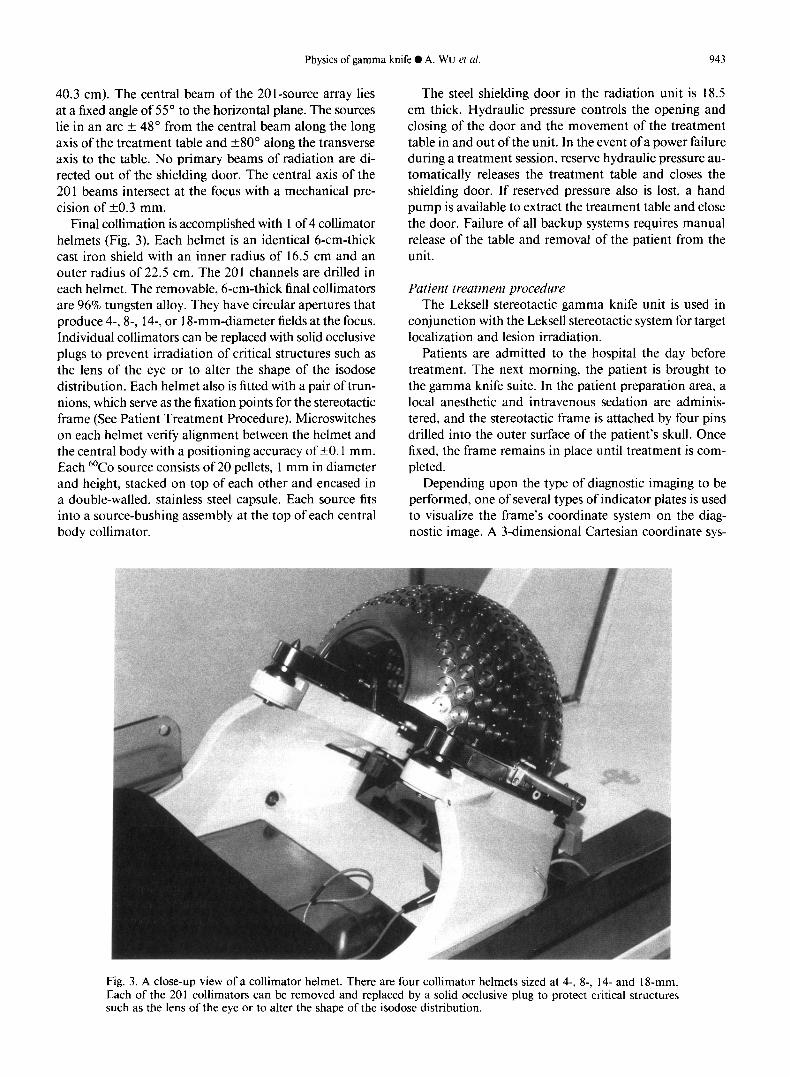
Final collimation is accomplished with 1 of 4 collimator helmets (Fig. 3). Each helmet is an identical 6-cm-thick cast iron shield with an inner radius of 16.5 cm and an outer radius of 22.5 cm. The 201 channels are drilled in each helmet. The removable, 6-cm-thick final collimators are 96% tungsten alloy. They have circular apertures that produce 4-, 8-, 14-, or 1 S-mm-diameter fields at the focus. Individual collimators can be replaced with solid occlusive plugs to prevent irradiation of critical structures such as the lens of the eye or to alter the shape of the isodose distribution. Each helmet also is fitted with a pair of trun- nions, which serve as the fixation points for the stereotactic frame (See Patient Treatment Procedure). Microswitches on each helmet verify alignment between the helmet and the central body with a positioning accuracy of +O. 1 mm. Each 6oCo source consists of 20 pellets, 1 mm in diameter and height, stacked on top of each other and encased in a double-walled, stainless steel capsule. Each source fits into a source-bushing assembly at the top of each central body collimator.
The steel shielding door in the radiation unit is 18.5 cm thick. Hydraulic pressure controls the opening and closing of the door and the movement of the treatment table in and out of the unit. In the event of a power failure during a treatment session, reserve hydraulic pressure au- tomatically releases the treatment table and closes the shielding door. If reserved pressure also is lost, a hand pump is available to extract the treatment table and close the door. Failure of all backup systems requires manual release of the table and removal of the patient from the unit.
Patient treatment procedure The Leksell stereotactic gamma knife unit is used in
conjunction with the Leksell stereotactic system for target localization and lesion irradiation.
Patients are admitted to the hospital the day before treatment. The next morning, the patient is brought to the gamma knife suite. In the patient preparation area, a local anesthetic and intravenous sedation are adminis- tered, and the stereotactic frame is attached by four pins drilled into the outer surface of the patient’s skull. Once fixed, the frame remains in place until treatment is com- pleted.
Depending upon the type of diagnostic imaging to be performed, one of several types of indicator plates is used to visualize the frame’s coordinate system on the diag- nostic image. A 3-dimensional Cartesian coordinate sys-
Fig. 3. A close-up view of a collimator helmet. There are four collimator helmets sized at 4-, 8-, I4- and 18-mm. Each of the 201 collimators can be removed and replaced by a solid occlusive plug to protect critical structures such as the lens of the eye or to alter the shape of the isodose distribution.
944 I. J. Radiation Oncology ??Biology 0 Physics April 1990, Volume 18, Number 4
tern (X, Y, Z) is used to locate the target coordinates in stereotactic space. The Z-axis (superior-inferior) of the coordinate system lies in the coronal plane of the patient, the X-axis (left-right) in the transverse plane, and the Y- axis (anterior-posterior) in the sagittal plane. The coor- dinate system is oriented such that the center of the helmet (the focus of the 201 sources) is at X = 100, Y = 100, and Z = 100, thus eliminating the use of negative coor- dinates. Currently magnetic resonance imaging, computed tomography, or cerebral angiography with orthogonal x-ray films are used for target localization.
After imaging is performed in the Radiology Depart- ment, the patient is returned to the preparation area in the gamma knife suite. The images are reviewed, and tar- get coordinates of each proposed radiation isocenter, or “shot”, are determined based on the size, shape, and lo- cation of the lesion as seen on the images. The patient is moved into the treatment room and placed on the table of the gamma unit. The target is moved to the focal point of the unit by setting the target’s Y and Z coordinates on an adjustable side pillar of the stereotactic frame and fixing the frame to the trunnions of the helmet, thereby defining the X coordinate. The angle made by the frame between the central source ray and the horizontal plane is called the “gamma angle” and is read from indicators on the trunnions. The gamma angle is determined by tilting the patient’s head. It is important to match the plane on the CT image with the X-Y plane of the unit. By shining a small penlight through each collimator in the helmet, ra- diation beams that would pass through the lens of either eye can be predicted. The appropriate collimators then are replaced with solid plugs. If more than one target is to be irradiated, this process is repeated for each target.
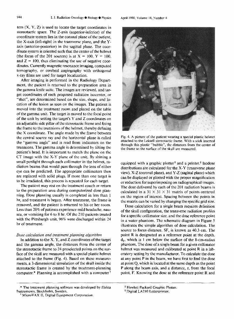
Fig. 4. A picture of the patient wearing a special plastic helmet attached to the Leksell stereotactic frame. With a stick inserted through this plastic “bubble”, the distances from the center of the frame to the surface of the skull are measured.
The patient may rest on the treatment couch or return to the preparation area during computerized dose plan- ning. Dose planning usually is completed in less than 1 hr, and treatment is begun. After treatment, the frame is removed, and the patient is returned to his or her room. Less than 20% of patients experience mild headache, nau- sea, or vomiting for 6 to 8 hr. Of the 2 10 patients treated with the Pittsburgh unit, 96% were discharged within 24 hr of treatment.
equipped with a graphic plotter* and a printer.§ Isodose distributions are calculated for the X-Y (transverse plane view), X-Z (coronal plane), and Y-Z (sag&al plane) which can be displayed or plotted with the proper magnification or reduction for superimposing on radiographical images. The dose delivered by each of the 20 1 radiation beams is calculated in a 3 1 X 31 X 31 matrix of points centered on the region of interest. Spacing between the points in the matrix can be varied by changing the specific grid size.
Dose calculation and treatment planning algorithm In addition to the X, Y, and Z coordinates of the target
and the gamma angle, the distances from the center of the stereotactic frame to 24 preselected points on the sur- face of the skull are measured with a special plastic helmet attached to the frame (Fig. 4). Based on these measure- ments, a 3-dimensional simulation of the skull inside the stereotactic frame is created by the treatment-planning computer.* Planning is accomplished with a computer+
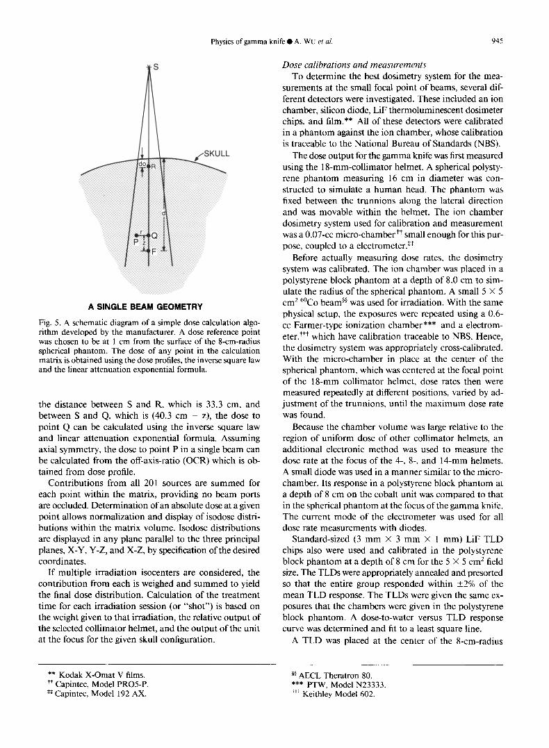
Dose calculation for a single beam requires definition of the skull configuration, the transverse radiation profiles for a specific collimator size, and the dose reference point in a water phantom. The schematic diagram in Figure 5 illustrates the simple algorithm of dose calculation. The source to focus distance, SF, is known as 40.3 cm. The point R is designated as a reference point at the depth, 4, which is 1 cm below the surface of the 8-cm-radius phantom. The dose of a single beam for a given collimator helmet was measured and calibrated at point R in a lab- oratory setting by the manufacturer. To calculate the dose at any point P in the beam, we have first to find the dose at point Q, which is located at the same depth as the point P along the beam axis, and a distance, z, from the focal point, F. Knowing the dose at the reference point R and
* The treatment planning software was developed by Elekta Instruments, Stockholm, Sweden.
+ MicroVAX II, Digital Equipment Corporation.
* Hewlett Packard Graphic Plotter. 5 Digital LA2 10 Letter-printer.
Physics of gamma knife 0 A. WU et al. 945
A SINGLE BEAM GEOMETRY
Fig. 5. A schematic diagram of a simple dose calculation algo- rithm developed by the manufacturer. A dose reference point was chosen to be at 1 cm from the surface of the 8-cm-radius spherical phantom. The dose of any point in the calculation matrix is obtained using the dose profiles, the inverse square law and the linear attenuation exponential formula.
the distance between S and R, which is 33.3 cm, and between S and Q, which is (40.3 cm - z), the dose to point Q can be calculated using the inverse square law and linear attenuation exponential formula. Assuming axial symmetry, the dose to point P in a single beam can be calculated from the off-axis-ratio (OCR) which is ob- tained from dose profile.
Contributions from all 201 sources are summed for each point within the matrix, providing no beam ports are occluded. Determination of an absolute dose at a given point allows normalization and display of isodose distri- butions within the matrix volume. Isodose distributions are displayed in any plane parallel to the three principal planes, X-Y, Y-Z, and X-Z, by specification of the desired coordinates.
If multiple irradiation isocenters are considered, the contribution from each is weighed and summed to yield the final dose distribution. Calculation of the treatment time for each irradiation session (or “shot”) is based on the weight given to that irradiation, the relative output of the selected collimator helmet, and the output of the unit at the focus for the given skull configuration.
** Kodak X-Omat V films. ++ Capintec, Model PROS-P. *# Capintec, Model 192 AX.
Dose calibrations and measurements To determine the best dosimetry system for the mea-
surements at the small focal point of beams, several dif- ferent detectors were investigated. These included an ion chamber, silicon diode, LiF thermoluminescent dosimeter chips, and film.** All of these detectors were calibrated in a phantom against the ion chamber, whose calibration is traceable to the National Bureau of Standards (NBS).
The dose output forthe gamma knife was first measured using the 1 &mm-collimator helmet. A spherical polysty- rene phantom measuring 16 cm in diameter was con- structed to simulate a human head. The phantom was fixed between the trunnions along the lateral direction and was movable within the helmet. The ion chamber dosimetry system used for calibration and measurement was a 0.07-cc micro-chamber++ small enough for this pur- pose, coupled to a electrometer.*’
Before actually measuring dose rates, the dosimetry system was calibrated. The ion chamber was placed in a polystyrene block phantom at a depth of 8.0 cm to sim- ulate the radius of the spherical phantom. A small 5 X 5 cm2 6oCo beam@ was used for irradiation. With the same physical setup, the exposures were repeated using a 0.6- cc Farmer-type ionization chamber*** and a electrom- eter +++ which have calibration traceable to NBS. Hence, the hosimetry system was appropriately cross-calibrated. With the micro-chamber in place at the center of the spherical phantom, which was centered at the focal point of the 18-mm collimator helmet, dose rates then were measured repeatedly at different positions, varied by ad- justment of the trunnions, until the maximum dose rate was found.
Because the chamber volume was large relative to the region of uniform dose of other collimator helmets, an additional electronic method was used to measure the dose rate at the focus of the 4-, 8-, and 14-mm helmets. A small diode was used in a manner similar to the micro- chamber. Its response in a polystyrene block phantom at a depth of 8 cm on the cobalt unit was compared to that in the spherical phantom at the focus of the gamma knife. The current mode of the electrometer was used for all dose rate measurements with diodes.
Standard-sized (3 mm X 3 mm X 1 mm) LiF TLD chips also were used and calibrated in the polystyrene block phantom at a depth of 8 cm for the 5 X 5 cm* field size. The TLDs were appropriately annealed and presorted so that the entire group responded within +2% of the mean TLD response. The TLDs were given the same ex- posures that the chambers were given in the polystyrene block phantom. A dose-to-water versus TLD response curve was determined and fit to a least square line.
A TLD was placed at the center of the S-cm-radius
@ AECL Theratron 80. *** PTW, Model N23333. +++ Keithley Model 602.
946 I. J. Radiation Oncology 0 Biology 0 Physics April 1990, Volume 18, Number 4
polystyrene sphere (p = l.O33g/cc) and exposed at the focus of the gamma knife unit. The l&mm helmet was used with all 201 cobalt source collimators open. The TLD response curve was used to determine the dose rate to water per minute at the center of the polystyrene sphere. The average reading of 11 TLDs, exposed at every 30” along the x-axis of the spherical phantom, determines the dose rate.
tom with a small beam of a 6oCo teletherapy machine against ion chamber measurements.
Mechanical alignment accuracy
To determine the “true” dose rate at the focus of the unit, the transit dose (dose accumulated during the table’s entry and exit from the focus) was subtracted from the total accumulated dose at the focus. The transit dose was determined as it was for the 6oCo teletherapy machine.
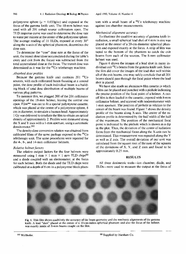
To illustrate the qualitive accuracy of gamma knife ir- radiation, a small spherical lead shot of 4 mm in size was placed at the center of a 20-cm diameter spherical phan- tom and exposed exactly at the focus. A strip of film was taped to the bottom of the phantom to catch the exit beams from each of the sources. The g-mm collimator helmet was used.
Absorbed dose projles Because the gamma knife unit contains 201 6oCo
sources, with each collimated beam focusing at a central point, the dose profile of each individual beam is a build- ing block of total dose distribution of multiple beams of various plug patterns.
Figure 6 shows the images of a lead shot in many in- dividual exit 6oCo beams from the gamma knife unit. Since the film did cover the images of the lead shot well within all of the exit beams, one may safely conclude that all 20 1 beams should pass through the focal point where the lead shot is placed.
To measure this, we plugged 200 of the 20 1 collimator openings of the l&mm helmet, leaving the central one open. Film** was cut to fit a special polystyrene cassette, which was placed at the center of a polystyrene sphere, 8 cm in diameter, to simulate a human head. Approximately 1 Gy was delivered to irradiate the film to obtain an optical density of approximately 2. Profiles were measured along the X and Y axes with a l-mm aperture, using a automatic densitometer.s*s
The density-dose conversion relation was obtained from calibrated films of the same package exposed to the 6oCo teletherapy unit. The same procedures were repeated for the 4-, 8-, and 14-mm collimator helmets.
Relative helmet factors The relative output factors for the four helmets were
measured using 1 mm X 1 mm X 1 mm TLD chips@” and a diode coupled with an electrometer, at the focus for each helmet. Both the diode and the TLD chips were calibrated at a depth of 8 cm in a polystyrene block phan-
We have also made an aluminum film cassette in which a film can be placed and punched with a pinhole indicating the precise position of the focal point of a helmet. A cut- off film is then loaded in the cassette, exposed with g-mm collimator helmet, and scanned with isodensitometer with 1 -mm aperture. The position of pinhole in relation to the center of the beam was found. Figure 7 shows the density profile of the beams along X-axis. The center of the ra- diation profile is determined by the half width of the half of the maximum. The position of the mechanical focal point is indicated by the pinhole which is shown as a dip in the plot. Thus, the deviation of the center of radiation focus from the mechanical focus along the X-axis can be determined. This measurement was repeated along the Y as well as Z axis. The overall deviation of our unit was calculated from the square root of the sum of the squares of the deviations of X, Y, and Z axes and found to be approximately 0.25 mm.
RESULTS
All three dosimetric tools-ion chamber, diode, and TLDs-were used to measure the output at the focus of
Fig. 6. This film shows qualitively the accuracy of the beam geometry and the mechanic alignments of the gamma knife. A lead “shot” placed at the center of a lo-cm-radius spherical phantom and also the focus of the helmet, was exactly inside all 8-mm beams caught on the film.
t*$ Wellhofer. 5g5 Supplied by Harshaw Co.
Physics of gamma knife 0 A. WU et al. 947
off axis km)
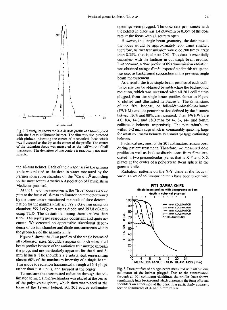
Fig. 7. This figure shows the X-axis dose profile of a film exposed with the 8-mm collimator helmet. The film was also punched with pinhole indicating the center of mechanical focus which was illustrated as the dip at the center of the profile. The center of the radiation focus was measured as the half-width-of-half maximum. The deviation of two centers is practically not mea- surable.
the 1 g-mm helmet. Each of their responses in the gamma knife was related to the dose in water measured by the Farmer ionization chamber on the 6oCo unit@ according to the most recent American Association of Physicists in Medicine protocol.
At the time of measurements, the “true” dose rate out- puts at the focus of 1 g-mm collimator helmet determined by the three above-mentioned methods of dose determi- nation for the gamma knife are 399.7 cGy/min using ion chamber, 399.3 cGy/min using diode, and 397.8 cG/min using TLD. The deviations among them are less than 0.5%. The results are reasonably consistent and quite ac- curate. We detected no appreciable directional depen- dence of the ion chamber and diode measurements within the geometry of the gamma knife.
Figure 8 shows the dose profiles of the single beams of all collimator sizes. Shoulders appear on both sides of all beam profiles because of the radiation transmitted through the plugs and are particularly apparent for the 4- and 8- mm helmets. The shoulders are substantial, representing almost 60% of the maximum intensity of a single beam. This is due to radiation transmitted through all 20 1 plugs, rather than just 1 plug, and focused at the center.
To measure the transmitted radiation through the col- limator helmet, a micro-chamber was placed at the center of the polystyrene sphere, which then was placed at the focus of the 1 g-mm helmet. All 201 source collimator
openings were plugged. The dose rate per minute with the helmet in place was 1.4 cGy/min or 0.35% of the dose rate at the focus with all sources open.
However, in a single beam geometry, the dose rate at the focus would be approximately 200 times smaller; therefore, helmet transmission would be 200 times larger than 0.35%, that is, almost 70%. This data is essentially consistent with the findings in our single beam profiles. Furthermore, a dose profile of this transmission radiation was obtained using a film** exposed under this setup and was used as background subtraction in the previous single beam measurement.
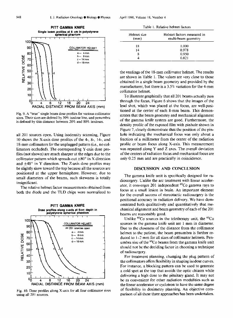
As a result, the true single beam profiles of each colli- mator size can be obtained by subtracting the background radiation, which was measured with all 201 collimators plugged, from the single beam profiles shown in Figure 7, plotted and illustrated in Figure 9. The dimensions of the 50% isodose, or full-width-of-half-maximum (FWHM), and the penumbra size, defined by the distance between 20% and 80%, are measured. Their FWHW’s are 4.0, 8.4, 14.0 and 18.0 mm for 4-, 8-, 14-, and g-mm collimator helmets, respectively. The penumbra’s are within l-2 mm range which is, comparably speaking, large for small collimator helmets, but small for large collimator helmets.
In clinical use, most of the 20 1 collimators remain open during patient treatment. Therefore, we measured dose profiles as well as isodose distributions from films irra- diated in two perpendicular planes that is X-Y and X-Z planes at the center of a polystyrene g-cm sphere in the gamma knife.
Radiation patterns on the X-Y plane at the focus of various sizes of collimator helmets have been taken with
PITT GAMMA KNIFE Single beam profiles with background at gem
depth in spherlcal phantom I 1 ! I I r 11 I1 1 I
a- 4 mm COLLIMATOR b- 8 mm COLLIMATOR C- 14 mm COLLIMATOR d- 18 mm COLLIMATOR
e-- BACKGROUND
10- 1 I I I I I I II 1 I I
‘0 4 6 12 16 20 24 RADIAL DISTANCE FROM BEAM AXIS (mm)
Fig. 8. Dose profiles of a single beam measured with all but one collimator of the helmet plugged. Due to the transmission through all 201 collimator shieldings, the profiles have shown significantly high background which appears in the form of broad shoulders on either side of the peak. It is particularly apparent for the collimators of 4- and 8-mm in size.
948 I. J. Radiation Oncology 0 Biology 0 Physics April 1990, Volume 18, Number 4
PITT GAMMA KNIFE Single beam profiles at 8 cm in polystyrene
spherical phantom I”““““” I
I I_ Oo 4
b- 8mm c-14mm
d-18mm
b c d
2 \
8 12 16 20 24
COLLIMATOR HELMET -
a- 4mm
RADIAL DISTANCE FROM BEAM AXIS (mm)
Fig. 9. A “true” single beam dose profiles for various collimator sizes. Their sizes are defined by 50% isodose line, and penumbra is defined by this distance between 20% and 80% isodoses.
all 201 sources open. Using isodensity scanning, Figure 10 shows the X-axis dose profiles of the 4-, 8-, 14-, and 18-mm collimators for the unplugged pattern (i.e., no col- limators occluded). The corresponding Y-axis dose pro- files (not shown) are much sharper at the edges due to the collimator pattern which spreads out +80” in X direction and +48” in Y direction. The Z-axis dose profiles may be slightly skew toward the top because all the sources are positioned at the upper hemisphere. However, due to small diameters of the beams, such skewness is totally insignificant.
The relative helmet factor measurements obtained from both the diode and the TLD chips were normalized to
PITT GAMMA KNIFE Dose profiles along x-axis at Bcm depth in
polystyrene spherical phantom I I I I I I I I I I I I
COLLIMATOR HELMET
All 201 SOWC~.S open
a- 4mm b- 8mm c-14mm d-18mm
‘0 4 8 12 16 20 24 RADIAL DISTANCE FROM BEAM AXIS (mm)
Fig. 10. Dose profiles along X-axis for all four collimator sizes using all 201 sources.
Table 1. Relative helmet factors
Helmet size (mm)
Helmet factors measured in multi-beam geometry
18 1 .ooo 14 0.978 8 0.950 4 0.821
the readings of the 18-mm collimator helmet. The results are shown in Table 1. The values are very close to those obtained in a single beam geometry and provided by the manufacturer, but there is a 3.5% variation for the 4-mm collimator helmet.
To illustrate graphically that all 20 1 beams actually pass through the focus, Figure 6 shows that the images of the lead shot, which was placed at the focus, are well-posi- tioned at the center of each 8-mm beam. This demon- strates that the beam geometry and mechanical alignment of the gamma knife system are good. Furthermore, the density profile of the exposed film with pinhole shown in Figure 7, clearly demonstrate that the position of the pin- hole indicating the mechanical focus was only about a fraction of a millimeter from the center of the radiation profile or beam focus along X-axis. This measurement was repeated along Y and Z axes. The overall deviation of the centers of radiation focus and mechanical focus are only 0.25 mm and are practically in coincidence.
DISCUSSION AND CONCLUSION
The gamma knife unit is specifically designed for ra- diosurgery. Unlike the arc treatment with linear acceler- ator, it converges 201 independent 6oCo gamma rays to focus at a small lesion in brain. An important element for the overall success of stereotactic radiosurgery is the positional accuracy in radiation delivery. We have dem- onstrated both qualitatively and quantitatively that me- chanical alignment and beam geometry of each of the 20 1 beams are reasonably good.
Unlike 6oCo sources in the teletherapy unit, the 6oCo sources in the gamma knife unit are 1 mm in diameter. Due to the closeness of the distance from the collimator helmet to the patient, the beam penumbra is further re- duced to l-2 mm for all sizes of collimator helmets. Pen- umbra size of the 6oCo beams from the gamma knife unit should not be the deciding factor in choosing a technique of radiosurgery.
For treatment planning, changing the plug pattern of the collimators offers flexibility in shaping isodose curves. For instance, a blocking pattern can be used to generate a cold spot at the top that avoids the optic chiasm while delivering a high dose to the pituitary gland. It may not be as convenient for other radiation modalities such as the linear accelerator or cyclotron to have the same degree of flexibility in dosimetry planning. An objective com- parison of all these three approaches has been undertaken.
Physics of gamma knife 0 A. WU et al.
REFERENCES
949
1. Anniko, M.; Arndt, J.; Noren, G. The human acoustic neu- rinoma in organ culture. II-tissue changes after gamma ir- radiation. Acta Otolaryngol. 9 1:223-235; 198 1.
2. Arcovito, G.; Piermattei, A.; D’Abramo, G.; Bassi, F. A. Dose Measurements and calculations of small fields for 9- MV x rays. Med. Phys. 12:779-784; 1985.
3. Backlund, E. 0.; Johansson, L.; Sarby, B. Studies on Cra- niopharyngiomas II. Treatment by Stereotactic Radiosur- gery. Acta Chir. Stand. 138:749-759; 1972.
4. Backlund, E. 0.; Rahn, T.; Sarby, B. Treatment of pinea- loma by stereotactic radiation surgery. Acta Radiol. Oncol. 13:368-376; 1974.
5. Barcia-Salorio, J.; Broseta, J.; Hernandez, G.; Barbera, J.; Brodes, V.; Ballester, B. Radiosurgical treatment of huge acoustic neurinomas. In: Szilka, G., ed. Stereotactic cerebral irradiation. INSERM Symposium No. 12. Amsterdam: El- sevier/North-Holland Biomedical Press; 1979:245-249.
6. DiTullio, M.; Malkasian, D.; Rand, R. A critical comparison of neurosurgical and otolaryngological approaches to acoustic neurinomas. J. Neurosurg. 48: 1- 12; 1978.
7. Engler, M. J.; Jones, G. L. Small-beam calibration by 0.6- and 0.2-cm3 ionization chambers. Med. Phys 11:822-826; 1984.
8. Fabrikant, J. I.; Lyman, J. T.; Hosobushi, Y. Stereotactic heavy-ion Bragg peak radiosurgery for intracranial vascular disorders: method for treatment of deep arterio-venous malformations. Br. J. Radiol. 57:479-490; 1984.
9. Hirch, A.; Noren, G.; Anderson, B. Audiologic findings after stereotactic radiosurgery in nine cases of acoustic neuri- nomas. Acta Otolaryngol. 88: 155- 160; 1979.
10. Houdek, P. V.; Van Buren, J. M.; Fayos, J. V. Dosimetry of small radiation fields for lo-MV x-rays. Med. Phys. 10: 333-336; 1982.
11. Kjellberg, R.; Hanami, T.; Davis, K. R.; Lyons, S. L.; Adams, R. D. Brag-peak proton-beam therapy for arteriovenous malformations of the brain. N. Engl. J. Med. 309:269-274; 1983.
12. Kjellberg, R.; Kliman, B. Bragg peak proton hypophysec- tomy for hyperpituitarism, induced hypo-pituitarism, and neoplasms. Prog. Neurol. Surg. 6:295-325; 1975.
13. Kjellberg, R.; Kliman, K. Proton radiosurgery for function- ing pituitary adenoma. In: Tindall, G., Collins, W., eds. Clinical management of pituitary disorder. New York: Ra- ven Press: 1979:3 15-334.
14. Larson, B.; Leksell, L.; Rexed, B. The use of high energy protons for cerebral surgery in man. Acta Chir. Stand. 125: 1-7; 1963.
15. Leksell, D. G. Stereotactic radiosurgery: present status and future trends. Neurol. Res. 9:60-68; 1987.
16. Leksell, L. The stereotactic method and radiosurgery of the brain. Acta Chir. Stand. 102:316-319; 1951.
17. Leksell, L. Cerebral radiosurgery. Acta Chir. Stand. 134: 585-595; 1968.
18. Leksell, L. Stereotactic radiosurgery. J. Neurol. Neurosurg. Psych. 46:797-803; 1983.
19. Lunsford, L. D.; Flickinger, J. C.; Lindner, G.; Maitz, A. Radiosurgery of the brain using the first United States 20 I Cobalt-60 source gamma knife. Neurosurgery 24: 15 1- 159; 1989.
20. Lutz, W.; Winston, K. R.; Maleki, N. A system for stereo- tactic radiosurgery with a linear accelerator. Int. J. Radiat. Oncol. Biol. Phys. 14:373-381; 1988.
2 1. Pike, B.; Podgorsak, E. B.; Peters, T. M.; Pla, C. Dose dis- tributions in dynamic stereotactic radiosurgery. Med. Phys. 14:780-789; 1987.
22. Rahn, T.; Anniko, M.; Arndt, J. Irradiation of human pi- tuitary adenomas in organ culture. In: Szikla, G., ed. Ste- reotactic cerebral irradiation. INSERM Symposium No. 12. Amsterdam: Elsevier/North-Holland Biomedical Press; 1979: 207-212.
23. Rice, R.; Hansen, J.; Svenson, G.: Siddon, R. Measurements of dose distributions in small beams of 6-MV X rays. Phys. Med. Biol. 32:1087-1099; 1987.
24. Schiffer, D.; Giordana, M.; Soffietti, R.; Sciolla, R.; San- nazzari, G.; Vasario, E. Effects of radiotherapy on the as- trocytomatous areas of malignant gliomas. J. Neuro. Oncol. 2: 167-175; 1984.
25. Steiner, L. Radiosurgery in cerebral arteriovenous malfor- mations. In: Flamm, E., Fein, J., eds. Textbook of cerebro- vascular surgery, Vol. 4, N.Y.: Springer Verlag; 1986: 1161- 1215.
26. Steiner, L.; Leksell, L.; Greitz, T.; Forster, D.; Backlund, E. 0. Stereotactic radiosurgery for cerebral arteriovenous malformations: report of a case. Acta Chir. Stand. 138:459- 464; 1972.
27. Walton, L.; Bombord, C. K.; Ramsden, D. The Sheffield stereotactic radiosurgery unit: physical characteristics and principles of operation. Br. J. Radiol. 60:897-906; 1987.