Embed Size (px)
Citation preview
1
RC Circuit Lab - Discovery PSI Physics – Capacitors and Resistors
Name______________________Date__________ Period_______
PurposeThe purpose of this lab will be to determine how capacitors behave in R-C circuits. The manner in which capacitors combine will also be studied.
Description/Background
The RC Circuit describes a circuit that consists of a resistor(s), a capacitor(s), and a voltage input into the circuit.
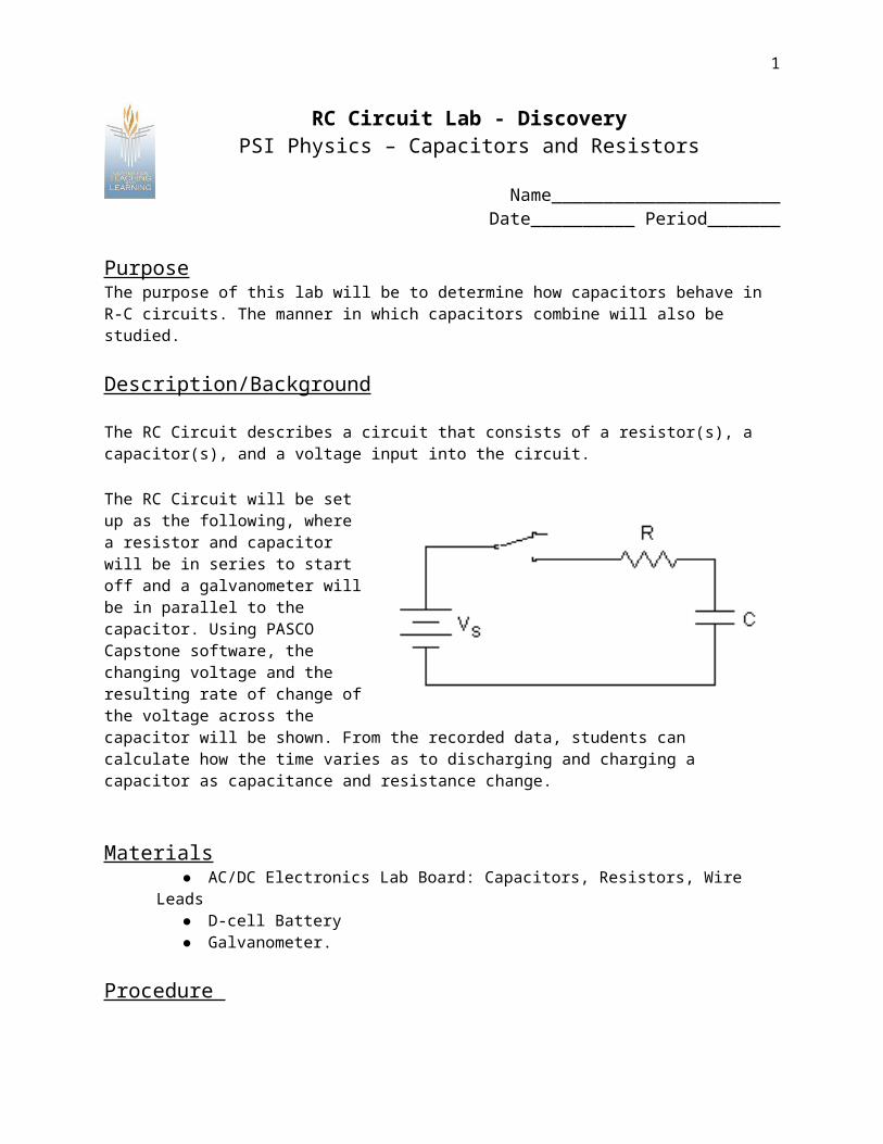
The RC Circuit will be set up as the following, where a resistor and capacitor will be in series to start off and a galvanometer will be in parallel to the capacitor. Using PASCO Capstone software, the changing voltage and the resulting rate of change of the voltage across the capacitor will be shown. From the recorded data, students can calculate how the time varies as to discharging and charging a capacitor as capacitance and resistance change.
Materials AC/DC Electronics Lab Board: Capacitors, Resistors, Wire Leads D-cell Battery Galvanometer.
Procedure

2
1. Connect the circuit shown in the figure below, using a 100 kΩ resistor and a 100 µF capacitor. Connect the galvanometer so the black “ground” lead is on the side of the capacitor that connects to the negative terminal of the battery and press the tare button on the galvanometer.
2. Start with no voltage on the capacitor and the switch off. If there is remaining voltage on the capacitor, use a piece of wire to “short” the two leads together, draining any remaining charge.
Figure 1.13. Open the Pasco Software and drag and drop the table and graph option on the
tools on the right side of the screen. After dropping it a data table and a graph should show up side by side. On the table select the for the Voltage and Time data to be displayed and for the graph choose Voltage v. Time.
4. Before closing the switch by pushing the button on the bottom of the screen in Pasco interface there should be a tool where you can increase and decrease frequency measured in Hz. To start Pasco automatically has it at 20 Hz but for the purpose of this lab it is preferred to set it at 40 Hz (If not getting required voltages try to increase Hz even more). Now click the record button the Voltage should be at 0 to start.
5. Now close the switch by pushing and holding the button down. Observe the voltage readings on the Pasco Interface, the voltage across the capacitor. How would you describe the manner in which the voltage changes?
6. If you now open the switch by releasing the button, the capacitor should remain at its present voltage with a very slow drop over time. This indicates that the charge you placed on the capacitor has no way to move back to neutralize the excess charges on the two plates.So now immediately stop the Recording and start a new one right after going to step seven immediately after.
7. Connect a wire between points A and C in the circuit shown in Figure 1.1 onto your circuit, allowing the charge to drain back through the resistor. Observe the voltage readings on the Pasco Interface as the charge flows back. How would you describe the manner in which the voltage falls?
8. Repeat steps 4-7 until you have a good feeling for the process of charging and discharging of a capacitor through a resistance.

3
9. Now repeat steps 4-7, this time recording the time taken to move from 0.0 volts to 0.95 volts while charging, tC, and the time taken to move from 1.5 volts to 0.55 volts while discharging, tD. Record your times along with the resistance and capacitance values.
10. Replace the 100 µF capacitor with a 330 µF capacitor. Repeat step 9, recording the charging and discharging times.. If a third value is available, include it in the data table, too.
11. Return to the original 100 µF capacitor, but put a 220 kΩ resistor in the circuit. Repeat step 9, recording your data. If a third resistor is provided, use it in the circuit, recording the data.
12. Return to the original 100 kΩ resistor, but use the 100 µF capacitor in series with the 330 µF capacitor.
13. Now repeat step 9, but with the 100 µF capacitor and the 100 kΩ resistor in parallel. Two pictures are provided to illustrate how they can be put in parallel.

4
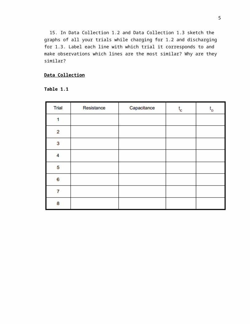
14. So far there should be 5 trials recorded in Data Collection 1.1 for the last 3 trials repeat step 13 but attempt to do it with two capacitors in parallel. Then after that the last two trials are a combination of your choice of resistors and capacitors in parallel or series. 15. In Data Collection 1.2 and Data Collection 1.3 sketch the graphs of all your trials while charging for 1.2 and discharging for 1.3. Label each line with which trial it corresponds to and make observations which lines are the most similar? Why are they similar?
Data Collection
Table 1.1
5
Graph 1.1 Charging
Graph 1.2 Discharging

6
Analysis Questions
1. Is there any notable relationship between time resistance and capacitance that you can infer? If so what data that you collected displays this idea?
2. Which trial had the longest time to charge? Why did it have the longest time to charge?
3. Which trial had the longest time to discharge? Why did it have the longest time to discharge?
4. What kind of function do the graphs of charging the capacitor seem most similar to? What kind of function do the graphs of discharging the capacitor seem most similar to?
5. Were there any trials that had results drastically different from the others if so give possible reasons why?
6. If you know how Capacitance and Voltage relate can you find charge? If so solve for charge in your first two trials?

7
7. Now calculate the energy in the capacitor for your first two trials. Where does this energy go after the capacitor has discharged?