Embed Size (px)
Citation preview

TEACHER MANUAL
E = mc²
©2014 Six Flags Theme Parks authorizes individual teachers who use this book permission
to make enough copies of material in it to satisfy the needs of their own students and classes.
Copying of this book or parts for resale is expressly prohibited. We would appreciate being
noted as the source, “Six Flags Great America, Chicago” in all materials used based on this
publication.
Six Flags Great America
542 North Route 21 Gurnee, Illinois 60031
(847)249-1952 sixflags.com
Why Take a Field Trip to an Amusement Park? If physics teachers could design the ultimate teaching laboratory, what would it be like? The laboratory would certainly contain devices for illustrating Newton's laws of motion, energy transformations, momentum conservation, and the dynamics of rotation. It would consist of large-scale apparatus so the phenomena could be easily observed and analyzed. Oh, and of course, the dream laboratory would allow the students an opportunity to not only witness the laws of physics in operation, but also feel them! Well, this dream laboratory does exist and is as close as Six Flags Great America! At Six Flags Great America, virtually all the topics included in the study of mechanics can be observed operating on a grand scale. Furthermore, phenomena, such as weightlessness, which can only be talked about in the classroom, may be experienced by anyone with sufficient courage. Students must quantify what they see and feel when doing amusement park physics. Unlike textbook problems, no data is given. Therefore, students must start from scratch. Heights of rides, periods of rotation, and lengths of roller coaster trains must be obtained before plugging data into equations learned in the classroom. Fortunately, only simple equipment is required to obtain data that will allow the calculation of such diverse quantities as a person's potential energy at the top of the American Eagle®?, the centripetal acceleration of the Columbia Carousel®, or the speed of a passenger on BATMAN The Ride®. Over the years, many schools have become involved with amusement park physics. This past May, "Physics Days" at Six Flags Great America attracted over 20,000 physics students from four states. These students would probably agree that Six Flags Great America provides the ultimate vehicles for learning physics!
PLANNING A TRIP TO SIX FLAGS GREAT AMERICA
I. PRE-TRIP PREPARATION AND SAFETY PRECAUSTIONS
1. Be sure permission slips indicate any special medical needs to allergies such as bee stings.
2. Instruct students to wear secure shoes or sneakers and bring appropriate clothing and sun blocks. This can mean a windbreaker for a chancy day or a change of clothing if they intend to go on water rides.
3. Assign students to lab groups of four to six, all members must be accounted for at all times.
In a larger group, no one will feel pressured to ride. Anyone wanting to ride will probably have a partner and non-riders will have people ask about sensations. Less equipment will be needed and enough people will be available to get the job done effectively.
4. Remind students to follow all safety requirements, such as seat belts and harnesses when
they get on a ride. The students’ activities at the Park must in no way interfere with the operation of any ride or park employees’ job. No restricted areas or safety zones are to be entered in efforts to obtain data. All data can be obtained from general public areas.
II. ORGANIZATIONAL SUGGESTIONS
1. Remind students that they are not required to go on any rides. They can do all of the workbook assignments and learn a great deal by watching and talking to people who do ride.
2. Tell students exactly where and when to meet the bus and arrange times and places during
the day where students can find you if they wish. If you choose to have students check in with you personally, set aside a large block of time so that students who are caught waiting in line for a ride will be able to check in.
3. Distribute tickets to students as they get off the bus so that entry to the park is efficient.
4. Suggest that students plan to use less dramatic rides for a good portion of their required
work. (Time in line is proportional to the popularity of a ride). III. USING THE HANDOUTS
1. The intent of the workbook is to show students that “doing physical science at the park adds an extra dimension; going on rides becomes more interesting and more exciting.”
2. A day or so before your field trip make up some data and go through one ride from the
workbook in class. Students will have a sense of how to use the pages most efficiently and familiarity will make the exercises seem less intimidating.
PLANNING A TRIP-CONTINUED
3. The ON THE BUS pages are important as they set the time for the day and also teach or
reinforce the concept of force - factors (The advantage of working in force-factors is that all students, regardless of mass, end up with roughly the same answers. This makes their work easier to check and gives them a way to compare experiences).
4. Completing the entire exercises handout would be overwhelming. Choose a series of
concepts and a maximum number (3 or 4) rides you want students to investigate.
5. Since certain rides illustrate almost exactly the same concepts, only one needs to be used.
6. Another option is to allow students to choose a ride not covered and develop materials which show how that ride illustrates physics concepts.
7. When checking student answers, please remember that human reaction times vary and the
speed of a ride depends on the temperature and time of day.
8. Many teachers have found it useful to have the workbook due at the end of the day. This insures that enough calculations are done at the park for the students to connect calculated results with the rides they have just experienced.
IV. EQUIPMENT NEEDED AT THE PARK
1. STOPWATCH. Many inexpensive ones are available and often at least one student in each group has a watch with stopwatch mode. Accuracy of 0.1 seconds is sufficient.
2. FORCE METER. Inexpensive commercial ones are available. They can also be made from a
plastic tube or a clear plastic tennis ball can using appropriate springs or rubber bands and fishing weights. The 2 oz. Weights work well with a relatively weak rubber band. (It is a nice opportunity to note that rubber bands are not linear.) Have students tether these to a wrist or belt with a rubber band that will break if necessary but will hold enough to prevent accidental loss on a ride.
3. PROTRACTOR. With a washer hanging on a string that passes through the vertex. A paper
photocopy pasted to cardboard also works reasonably well. The commercial version, sometimes called an inclinometer, has the advantage of being protected from air currents.
4. MEASURING STRING. Use a film can for storage. Knot one end of a cord and secure it in a
notch in the can. Measure out about 2 m of string making a knot or a mark with indelible market very 10 cm. Wind the string around the can. Secure the free end in a second notch and snap on the top. A local film processor will often save film cans, if asked. Another option is having students pre-measure their paces.
5. CALCULATOR AND PENCIL OR ERASABLE PEN.
6. ZIPLOCK PLASTIC BAG. This is a necessity to keep your workbook dry and all other
materials together.
7. ELECTRONIC DATA COLLECTION INSTRUMENTS. These instruments are helpful but not necessary. For more information Contact Pasco Scientific or Vernier Software and Technology.
LEARNING GOALS I. COGNITIVE GOAL: Upon the completion of the activities, the student will have an
enhanced understanding of the following laws and concepts of physics on the macroscopic scale:
-Conservation of Energy -Conservation of Momentum -Work -Power -Force -Newton's Laws of Motion -Kinematics -Rotational motion -Friction The student will: 1. Apply the principles of conservation of energy and kinematics to determine the velocity
and acceleration of an object after falling through a given vertical distance in a gravitational field.
2. Calculate the momentum of objects and qualitatively determine conservation of
momentum (particularly on bumper cars) 3. Calculate the work done by friction on roller coasters. 4. Estimate the power required to haul a roller coaster and its contents up the high rise. 5. Calculate the centripetal acceleration of a passenger in a circular motion ride by the use
of an accelerometer. 6. Determine the forces acting on a passenger in circular motion rides. 7. Measure the linear displacement of a chair on the swings as it moves through a
complete revolution. 8. Apply the method of triangulation to determine heights of and distances to various
structures. 9. Apply Newton's Laws of Motion to explain the effect of forces on passengers on various
rides. 10. Measure and record their personal physiological responses to their experiences during
amusement park activities.
Learning Goals-Continued II. ATTITUDES A. GOAL: upon completion of the activities, the student will develop a positive
attitude toward the physical sciences. The student will: 1. Be motivated to study physics by being challenged with a meaningful task
that allows them to accurately predict personal experience. 2. Gain an appreciation of the physics involved in the design and engineering
of the rides. B. GOAL: Upon completion of the activities, the student will bridge the gap between
school work and life education by seeing them as not isolated from one another. 1. Gain an appreciation of the applicability of physical principles studied in
the classroom to large scale phenomena. 2. Be encouraged to work as a member of a team in order to attain common
goals.
The National Science Education Standards can be found at: http://www.nap.edu/readingroom/books/nses/html/ or: http://www.mcrel.org/standards-benchmarks/
National Academy of Sciences 500 Fifth Street, N.W., Washington, DC 20001 Or the Project 2061 Benchmarks of the American Association for the Advancement of Science at: http://www.project2061.org/tools/benchol/bolintro.htm Project 2061 AAAS 1200 New York Avenue, NW Washington, DC 20005
OBJECTIVES Participants should be able to do the following. Roller Coasters 1. Identify points on a typical roller coaster track for maximum gravitational potential
energy, maximum kinetic energy, minimum gravitational potential energy, and minimum kinetic energy.
2. Plot kinetic energy, gravitational potential energy, and total mechanical energy versus
height. 3. Calculate the work done by friction as the roller coaster travels from one elevation to
another. Calculate the work due to friction for one round trip of the roller coaster ride. 4. Calculate the minimum power and horsepower required to lift a roller coaster to its
highest point. 5. Calculate the force of the seat on a passenger for various clock positions in a vertical
circle. 6. Use the work-energy theorem and the conservation of energy to calculate the speed of
an object after falling through a given vertical height. 7. Use a homemade accelerometer to: (a) calculate the acceleration of a roller coaster
down an incline; (b) determine various heights in the park using triangulation. 8. Relate Newton's Law's of motion to the motion of passengers for various rides. Bumpers Cars 1. Analyze collisions between cars to determine whether momentum and kinetic energy
are conserved in the interaction of two or more bodies. 2. List similarities between bumper cars and gas molecules confined in a container. 3. List examples of the second law of thermodynamics. 4. Recognize the role of the rubber bumpers during a collision. 5. Draw a simple electrical circuit diagram to explain the electrical power source for each
car.
OBJECTIVES-Continued Circular Motion Rides 1. Produce a force diagram for a typical rider in the Columbia Carousel. 2. Using two different methods, calculate the centripetal acceleration of a passenger in a
horizontal motion ride. 3. Explain the role of friction using appropriate force diagrams for a typical rider on a
uniform circular motion ride. 4. Produce velocity and force diagrams for riders at various clock positions. 5. Describe position, velocity, and acceleration for a person riding on the carousel. 6. Relate speed, radius of curvature, and angle of bank for roller coaster turns. Miscellaneous Keep a journal: A. describing procedures for collecting appropriate data. B. calculating answers to questions showing appropriate equations and units.
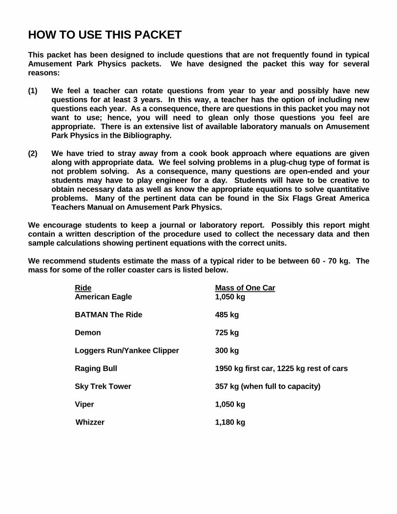
HOW TO USE THIS PACKET
This packet has been designed to include questions that are not frequently found in typical Amusement Park Physics packets. We have designed the packet this way for several reasons: (1) We feel a teacher can rotate questions from year to year and possibly have new
questions for at least 3 years. In this way, a teacher has the option of including new questions each year. As a consequence, there are questions in this packet you may not want to use; hence, you will need to glean only those questions you feel are appropriate. There is an extensive list of available laboratory manuals on Amusement Park Physics in the Bibliography.
(2) We have tried to stray away from a cook book approach where equations are given
along with appropriate data. We feel solving problems in a plug-chug type of format is not problem solving. As a consequence, many questions are open-ended and your students may have to play engineer for a day. Students will have to be creative to obtain necessary data as well as know the appropriate equations to solve quantitative problems. Many of the pertinent data can be found in the Six Flags Great America Teachers Manual on Amusement Park Physics.
We encourage students to keep a journal or laboratory report. Possibly this report might contain a written description of the procedure used to collect the necessary data and then sample calculations showing pertinent equations with the correct units. We recommend students estimate the mass of a typical rider to be between 60 - 70 kg. The mass for some of the roller coaster cars is listed below. Ride Mass of One Car American Eagle 1,050 kg BATMAN The Ride 485 kg Demon 725 kg Loggers Run/Yankee Clipper 300 kg
Raging Bull 1950 kg first car, 1225 kg rest of cars Sky Trek Tower 357 kg (when full to capacity) Viper 1,050 kg Whizzer 1,180 kg
SUGGESTIONS FOR TAKING MEASUREMENTS TIME The timings that are required to work out the problems can easily be measured by using a watch with a second hand or a digital watch with a stopwatch mode. When measuring the period of a ride that involves harmonic or circular motion, measure the time for several repetitions of the motion. This will give a better estimate of the period of motion than just measuring one repetition. You may want to measure the time two or three trails and then average them. DISTANCE Since you cannot interfere with the normal operation of the rides, you will not be able to directly measure heights, diameters, etc. Most of the distances can be measured remotely using the following methods. They will give you a reasonable estimate. Try to keep consistent units, i.e. meters, centimeters, etc., to make calculations easier. Pacing: Determine the length of your stride by walking at your normal rate over a
measured distance. Divide the distance by the number of steps and you can get the average distance per step. Knowing this, you can pace off horizontal distances.
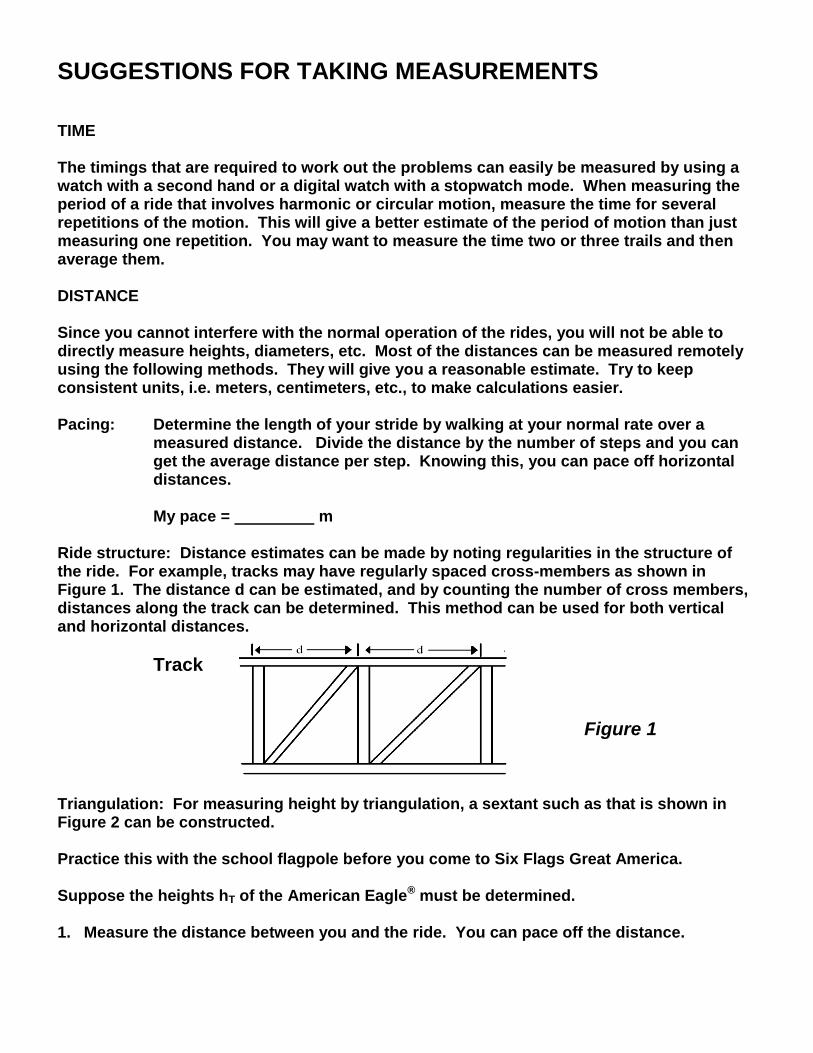
My pace = m Ride structure: Distance estimates can be made by noting regularities in the structure of the ride. For example, tracks may have regularly spaced cross-members as shown in Figure 1. The distance d can be estimated, and by counting the number of cross members, distances along the track can be determined. This method can be used for both vertical and horizontal distances.
Track Figure 1 Triangulation: For measuring height by triangulation, a sextant such as that is shown in Figure 2 can be constructed. Practice this with the school flagpole before you come to Six Flags Great America. Suppose the heights hT of the American Eagle® must be determined. 1. Measure the distance between you and the ride. You can pace off the distance.
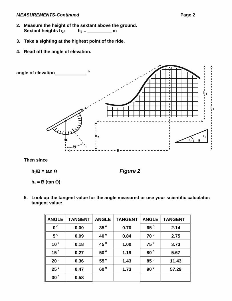
MEASUREMENTS-Continued Page 2 2. Measure the height of the sextant above the ground. Sextant heights h2: h2 = m 3. Take a sighting at the highest point of the ride. 4. Read off the angle of elevation.
angle of elevation o
Then since
h1/B = tan Ө Figure 2
h1 = B (tan Ө) 5. Look up the tangent value for the angle measured or use your scientific calculator: tangent value:
ANGLE TANGENT ANGLE TANGENT ANGLE TANGENT
0 o 0.00 35 o 0.70 65 o 2.14
5 o 0.09 40 o 0.84 70 o 2.75
10 o 0.18 45 o 1.00 75 o 3.73
15 o 0.27 50 o 1.19 80 o 5.67
20 o 0.36 55 o 1.43 85 o 11.43
25 o 0.47 60 o 1.73 90 o 57.29
30 o 0.58
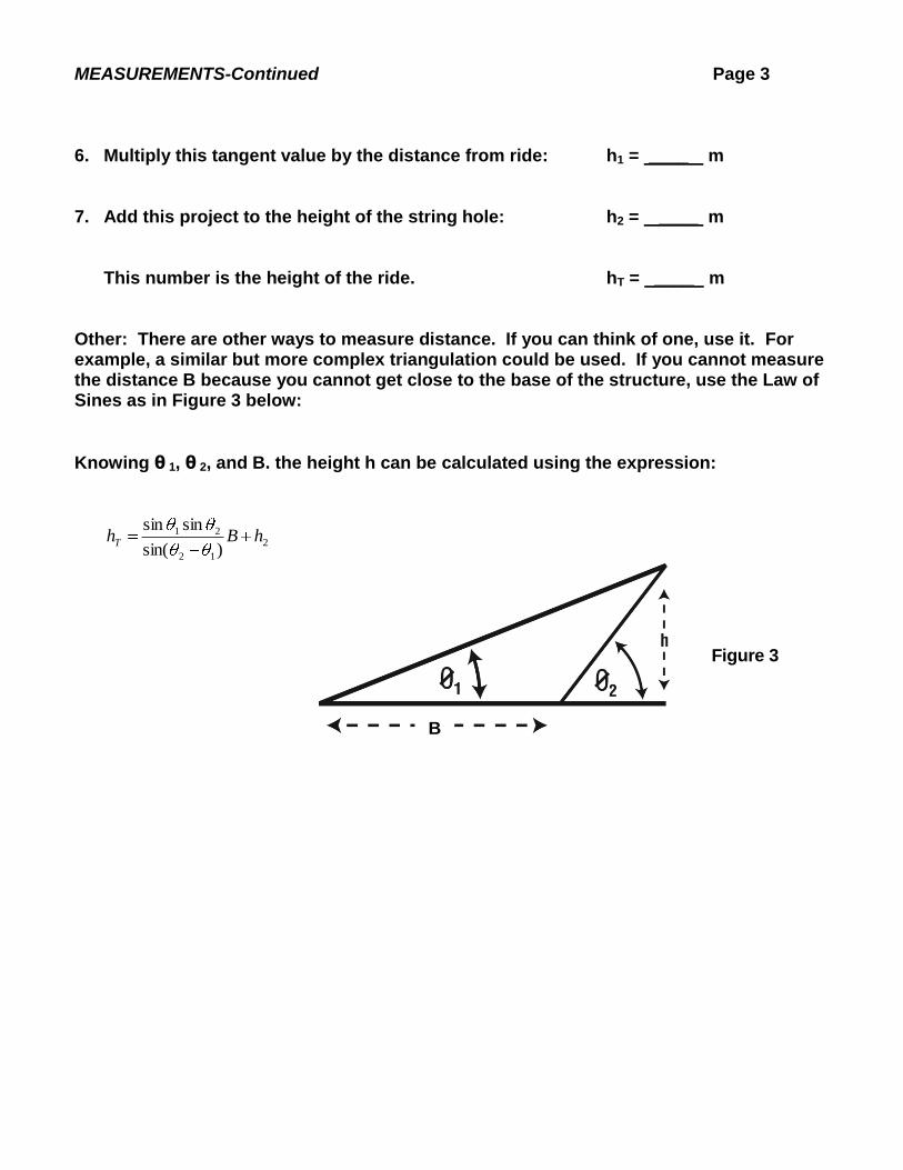
MEASUREMENTS-Continued Page 3 6. Multiply this tangent value by the distance from ride: h1 = ____ m 7. Add this project to the height of the string hole: h2 = ____ m This number is the height of the ride. hT = ____ m Other: There are other ways to measure distance. If you can think of one, use it. For example, a similar but more complex triangulation could be used. If you cannot measure the distance B because you cannot get close to the base of the structure, use the Law of Sines as in Figure 3 below:
Knowing θ 1, θ 2, and B. the height h can be calculated using the expression:
2
12
21
)sin(
sinsinhBhT
Figure 3
B
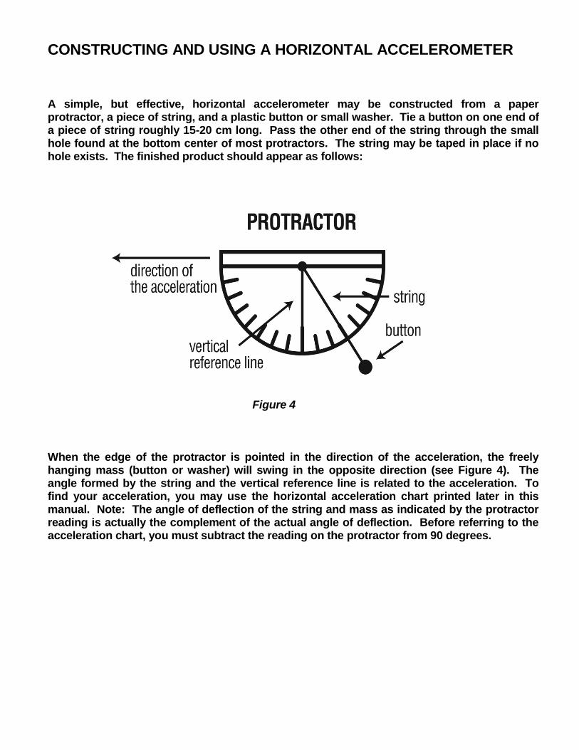
CONSTRUCTING AND USING A HORIZONTAL ACCELEROMETER A simple, but effective, horizontal accelerometer may be constructed from a paper protractor, a piece of string, and a plastic button or small washer. Tie a button on one end of a piece of string roughly 15-20 cm long. Pass the other end of the string through the small hole found at the bottom center of most protractors. The string may be taped in place if no hole exists. The finished product should appear as follows: Figure 4 When the edge of the protractor is pointed in the direction of the acceleration, the freely hanging mass (button or washer) will swing in the opposite direction (see Figure 4). The angle formed by the string and the vertical reference line is related to the acceleration. To find your acceleration, you may use the horizontal acceleration chart printed later in this manual. Note: The angle of deflection of the string and mass as indicated by the protractor reading is actually the complement of the actual angle of deflection. Before referring to the acceleration chart, you must subtract the reading on the protractor from 90 degrees.
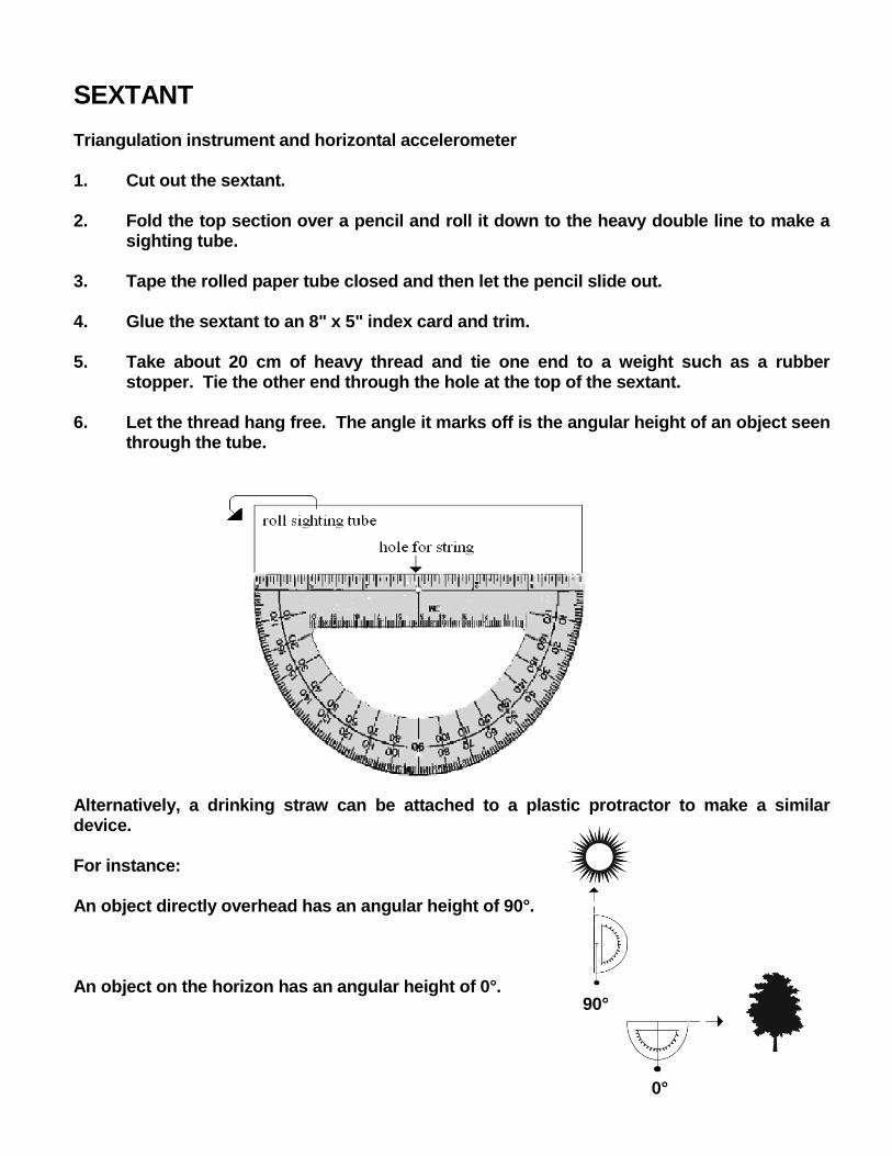
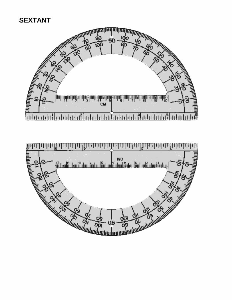
SEXTANT Triangulation instrument and horizontal accelerometer 1. Cut out the sextant. 2. Fold the top section over a pencil and roll it down to the heavy double line to make a
sighting tube. 3. Tape the rolled paper tube closed and then let the pencil slide out. 4. Glue the sextant to an 8" x 5" index card and trim. 5. Take about 20 cm of heavy thread and tie one end to a weight such as a rubber
stopper. Tie the other end through the hole at the top of the sextant. 6. Let the thread hang free. The angle it marks off is the angular height of an object seen
through the tube. Alternatively, a drinking straw can be attached to a plastic protractor to make a similar device. For instance: An object directly overhead has an angular height of 90°. An object on the horizon has an angular height of 0°.
90°
0°
SEXTANT
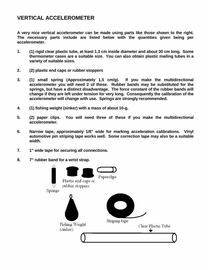
VERTICAL ACCELEROMETER A very nice vertical accelerometer can be made using parts like those shown to the right. The necessary parts include are listed below with the quantities given being per accelerometer. 1. (1) rigid clear plastic tube, at least 1.3 cm inside diameter and about 30 cm long. Some
thermometer cases are a suitable size. You can also obtain plastic mailing tubes in a variety of suitable sizes.
2. (2) plastic end caps or rubber stoppers 3. (1) small spring (Approximately 1.5 cm/g). If you make the multidirectional
accelerometer you will need 2 of these. Rubber bands may be substituted for the springs, but have a distinct disadvantage. The force constant of the rubber bands will change if they are left under tension for very long. Consequently the calibration of the accelerometer will change with use. Springs are strongly recommended.
4. (1) fishing weight (sinker) with a mass of about 10-g. 5. (2) paper clips. You will need three of these if you make the multidirectional
accelerometer. 6. Narrow tape, approximately 1/8" wide for marking acceleration calibrations. Vinyl
automotive pin striping tape works well. Some correction tape may also be a suitable width.
7. 1" wide tape for securing all connections. 8. 7" rubber band for a wrist strap.
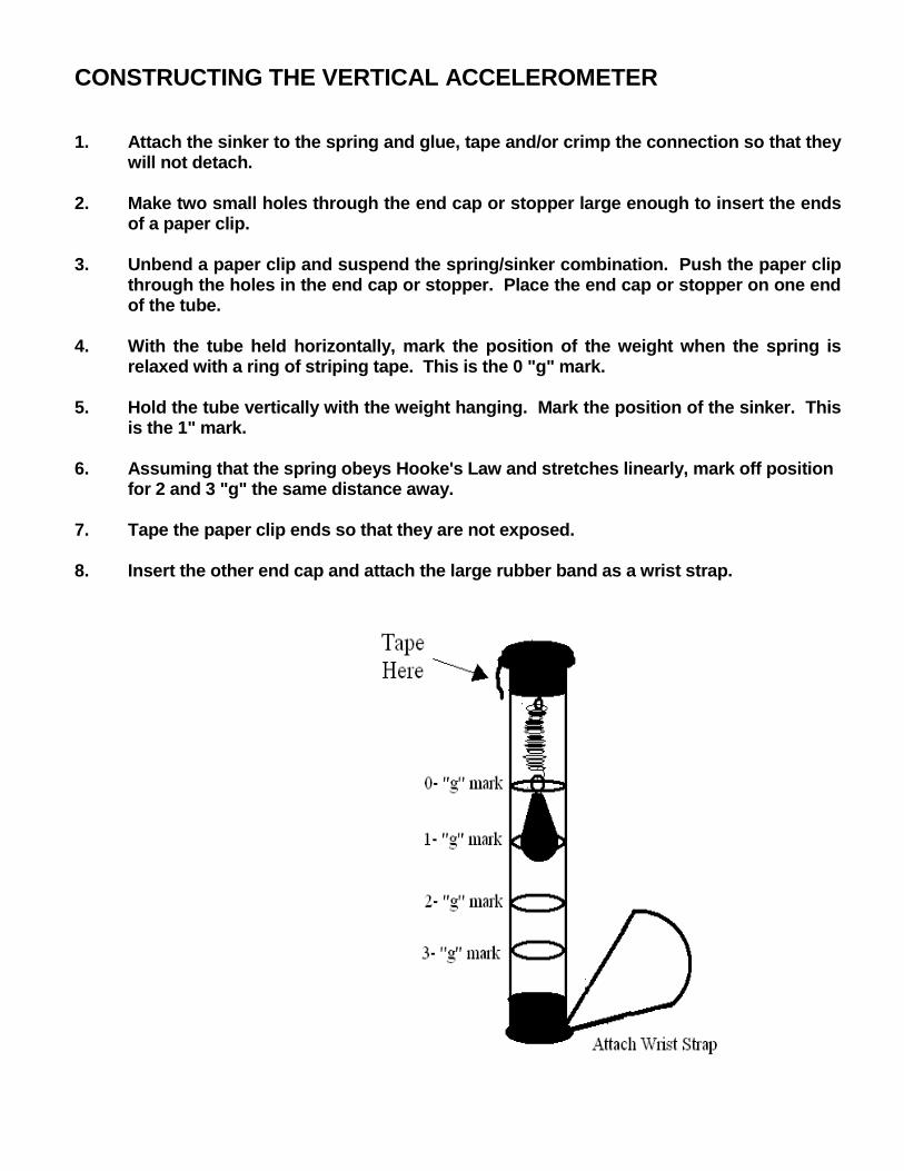
CONSTRUCTING THE VERTICAL ACCELEROMETER 1. Attach the sinker to the spring and glue, tape and/or crimp the connection so that they
will not detach. 2. Make two small holes through the end cap or stopper large enough to insert the ends
of a paper clip. 3. Unbend a paper clip and suspend the spring/sinker combination. Push the paper clip
through the holes in the end cap or stopper. Place the end cap or stopper on one end of the tube.
4. With the tube held horizontally, mark the position of the weight when the spring is
relaxed with a ring of striping tape. This is the 0 "g" mark. 5. Hold the tube vertically with the weight hanging. Mark the position of the sinker. This
is the 1" mark. 6. Assuming that the spring obeys Hooke's Law and stretches linearly, mark off position
for 2 and 3 "g" the same distance away. 7. Tape the paper clip ends so that they are not exposed. 8. Insert the other end cap and attach the large rubber band as a wrist strap.
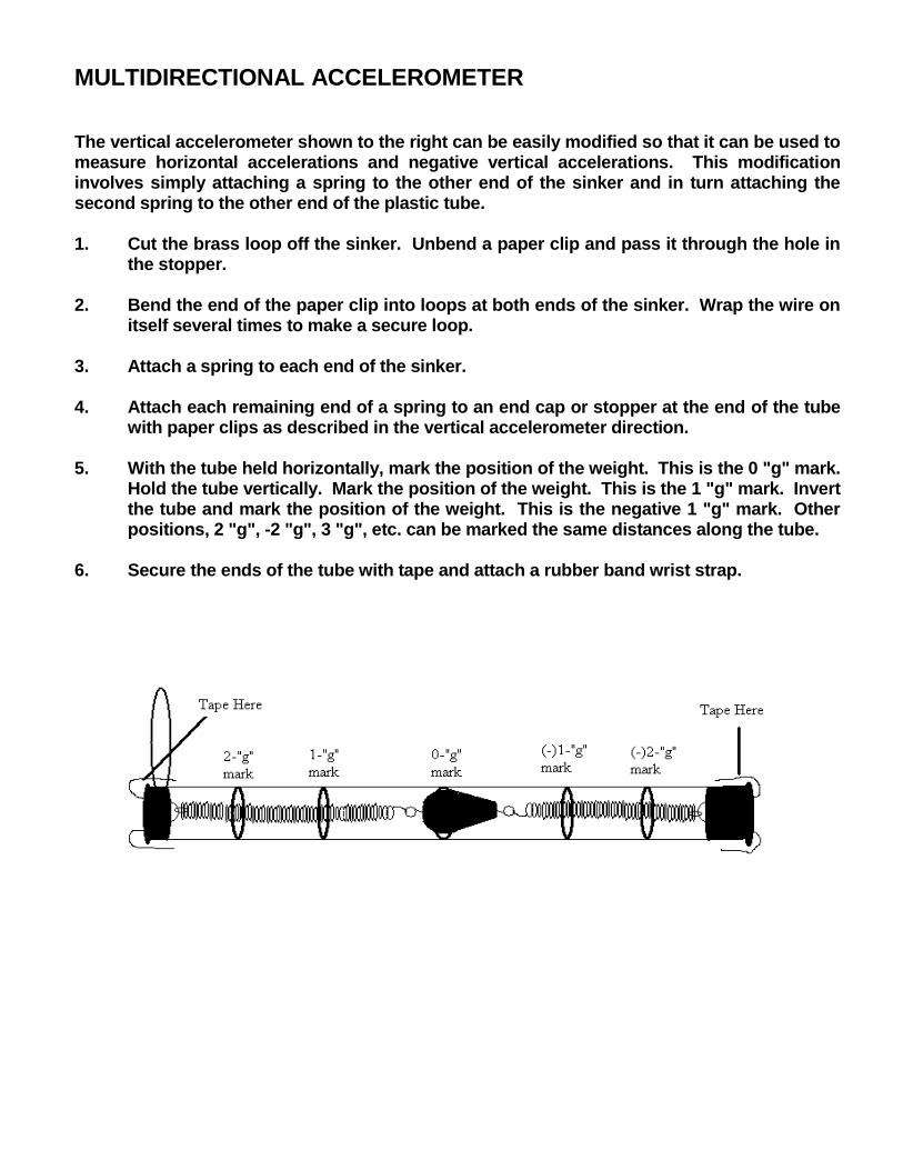
MULTIDIRECTIONAL ACCELEROMETER The vertical accelerometer shown to the right can be easily modified so that it can be used to measure horizontal accelerations and negative vertical accelerations. This modification involves simply attaching a spring to the other end of the sinker and in turn attaching the second spring to the other end of the plastic tube. 1. Cut the brass loop off the sinker. Unbend a paper clip and pass it through the hole in
the stopper. 2. Bend the end of the paper clip into loops at both ends of the sinker. Wrap the wire on
itself several times to make a secure loop. 3. Attach a spring to each end of the sinker. 4. Attach each remaining end of a spring to an end cap or stopper at the end of the tube
with paper clips as described in the vertical accelerometer direction. 5. With the tube held horizontally, mark the position of the weight. This is the 0 "g" mark.
Hold the tube vertically. Mark the position of the weight. This is the 1 "g" mark. Invert the tube and mark the position of the weight. This is the negative 1 "g" mark. Other positions, 2 "g", -2 "g", 3 "g", etc. can be marked the same distances along the tube.
6. Secure the ends of the tube with tape and attach a rubber band wrist strap.
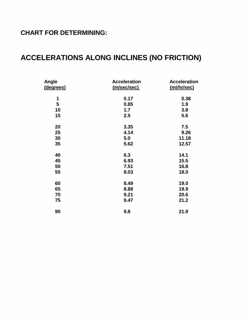
CHART FOR DETERMINING:
ACCELERATIONS ALONG INCLINES (NO FRICTION) Angle Acceleration Acceleration (degrees) (m/sec/sec) (mi/hr/sec) 1 0.17 0.38 5 0.85 1.9 10 1.7 3.8 15 2.5 5.6 20 3.35 7.5 25 4.14 9.26 30 5.0 11.18 35 5.62 12.57 40 6.3 14.1 45 6.93 15.5 50 7.51 16.8 55 8.03 18.0 60 8.49 19.0 65 8.88 19.9 70 9.21 20.6 75 9.47 21.2 90 9.8 21.9
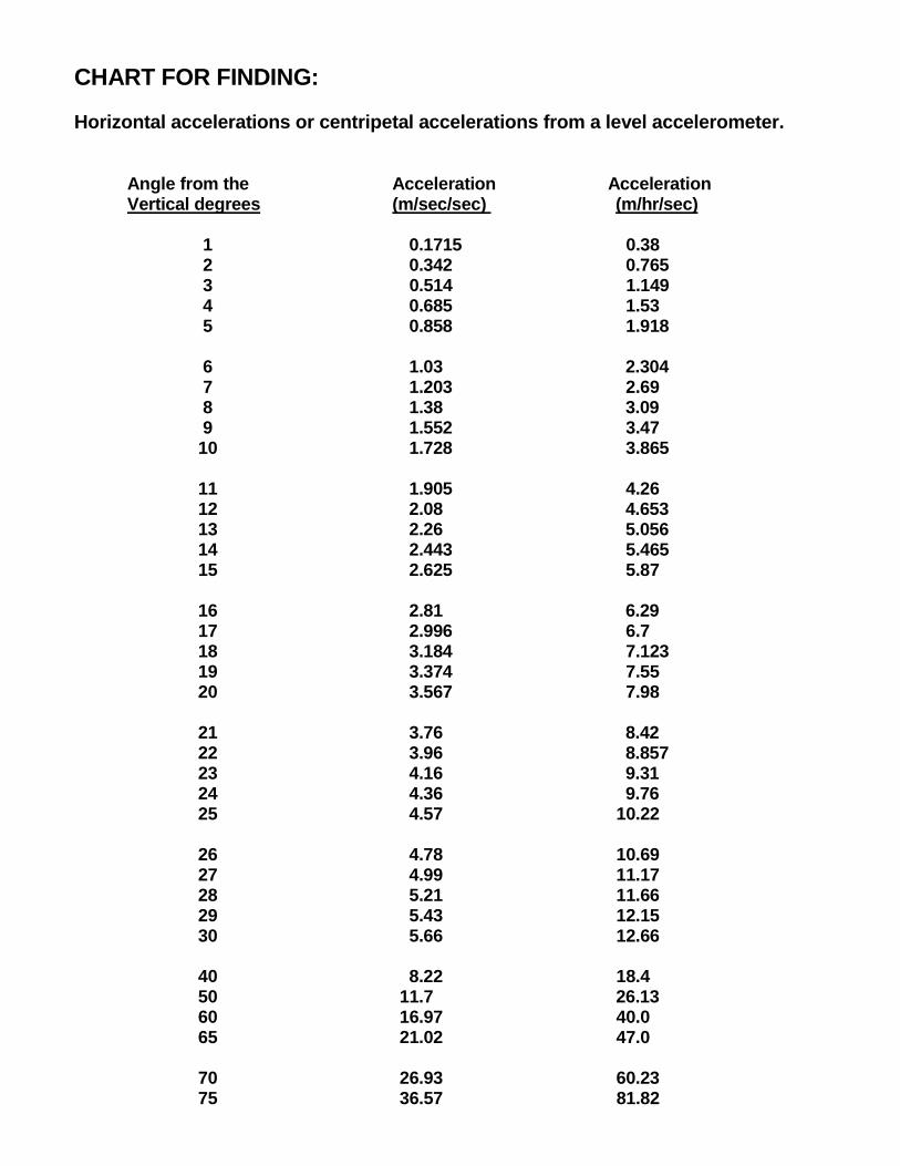
CHART FOR FINDING:
Horizontal accelerations or centripetal accelerations from a level accelerometer. Angle from the Acceleration Acceleration Vertical degrees (m/sec/sec) (m/hr/sec) 1 0.1715 0.38 2 0.342 0.765 3 0.514 1.149 4 0.685 1.53 5 0.858 1.918 6 1.03 2.304 7 1.203 2.69 8 1.38 3.09 9 1.552 3.47 10 1.728 3.865 11 1.905 4.26 12 2.08 4.653 13 2.26 5.056 14 2.443 5.465 15 2.625 5.87 16 2.81 6.29 17 2.996 6.7 18 3.184 7.123 19 3.374 7.55 20 3.567 7.98 21 3.76 8.42 22 3.96 8.857 23 4.16 9.31 24 4.36 9.76 25 4.57 10.22 26 4.78 10.69 27 4.99 11.17 28 5.21 11.66 29 5.43 12.15 30 5.66 12.66 40 8.22 18.4 50 11.7 26.13 60 16.97 40.0 65 21.02 47.0 70 26.93 60.23 75 36.57 81.82
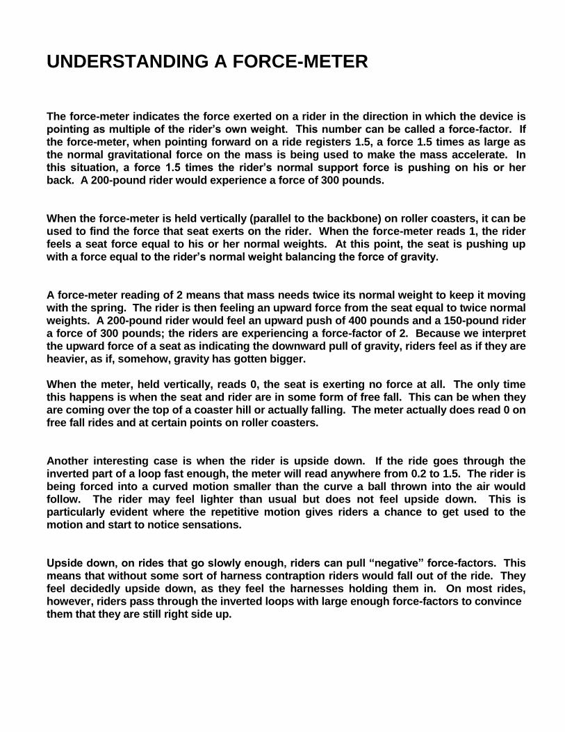
UNDERSTANDING A FORCE-METER The force-meter indicates the force exerted on a rider in the direction in which the device is pointing as multiple of the rider’s own weight. This number can be called a force-factor. If the force-meter, when pointing forward on a ride registers 1.5, a force 1.5 times as large as the normal gravitational force on the mass is being used to make the mass accelerate. In this situation, a force 1.5 times the rider’s normal support force is pushing on his or her back. A 200-pound rider would experience a force of 300 pounds. When the force-meter is held vertically (parallel to the backbone) on roller coasters, it can be used to find the force that seat exerts on the rider. When the force-meter reads 1, the rider feels a seat force equal to his or her normal weights. At this point, the seat is pushing up with a force equal to the rider’s normal weight balancing the force of gravity. A force-meter reading of 2 means that mass needs twice its normal weight to keep it moving with the spring. The rider is then feeling an upward force from the seat equal to twice normal weights. A 200-pound rider would feel an upward push of 400 pounds and a 150-pound rider a force of 300 pounds; the riders are experiencing a force-factor of 2. Because we interpret the upward force of a seat as indicating the downward pull of gravity, riders feel as if they are heavier, as if, somehow, gravity has gotten bigger. When the meter, held vertically, reads 0, the seat is exerting no force at all. The only time this happens is when the seat and rider are in some form of free fall. This can be when they are coming over the top of a coaster hill or actually falling. The meter actually does read 0 on free fall rides and at certain points on roller coasters. Another interesting case is when the rider is upside down. If the ride goes through the inverted part of a loop fast enough, the meter will read anywhere from 0.2 to 1.5. The rider is being forced into a curved motion smaller than the curve a ball thrown into the air would follow. The rider may feel lighter than usual but does not feel upside down. This is particularly evident where the repetitive motion gives riders a chance to get used to the motion and start to notice sensations. Upside down, on rides that go slowly enough, riders can pull “negative” force-factors. This means that without some sort of harness contraption riders would fall out of the ride. They feel decidedly upside down, as they feel the harnesses holding them in. On most rides, however, riders pass through the inverted loops with large enough force-factors to convince them that they are still right side up.
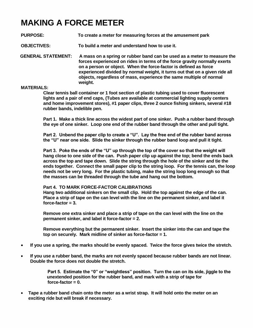
MAKING A FORCE METER PURPOSE: To create a meter for measuring forces at the amusement park OBJECTIVES: To build a meter and understand how to use it.
GENERAL STATEMENT: A mass on a spring or rubber band can be used as a meter to measure the forces experienced on rides in terms of the force gravity normally exerts on a person or object. When the force-factor is defined as force experienced divided by normal weight, it turns out that on a given ride all objects, regardless of mass, experience the same multiple of normal weight.
MATERIALS: Clear tennis ball container or 1 foot section of plastic tubing used to cover fluorescent lights and a pair of end caps, (Tubes are available at commercial lighting supply centers and home improvement stores), #1 paper clips, three 2 ounce fishing sinkers, several #18 rubber bands, indelible pen. Part 1. Make a thick line across the widest part of one sinker. Push a rubber band through the eye of one sinker. Loop one end of the rubber band through the other and pull tight. Part 2. Unbend the paper clip to create a “U”. Lay the free end of the rubber band across the “U” near one side. Slide the sinker through the rubber band loop and pull it tight. Part 3. Poke the ends of the “U” up through the top of the cover so that the weight will hang close to one side of the can. Push paper clip up against the top; bend the ends back across the top and tape down. Slide the string through the hole of the sinker and tie the ends together. Connect the small paper clip to the string loop. For the tennis can, the loop needs not be very long. For the plastic tubing, make the string loop long enough so that the masses can be threaded through the tube and hang out the bottom. Part 4. TO MARK FORCE-FACTOR CALIBRATIONS Hang two additional sinkers on the small clip. Hold the top against the edge of the can. Place a strip of tape on the can level with the line on the permanent sinker, and label it force-factor = 3. Remove one extra sinker and place a strip of tape on the can level with the line on the permanent sinker, and label it force-factor = 2. Remove everything but the permanent sinker. Insert the sinker into the can and tape the top on securely. Mark midline of sinker as force-factor = 1.
If you use a spring, the marks should be evenly spaced. Twice the force gives twice the stretch.
If you use a rubber band, the marks are not evenly spaced because rubber bands are not linear. Double the force does not double the stretch.
Part 5. Estimate the “0” or “weightless” position. Turn the can on its side, jiggle to the unextended position for the rubber band, and mark with a strip of tape for
force-factor = 0.
Tape a rubber band chain onto the meter as a wrist strap. It will hold onto the meter on an exciting ride but will break if necessary.
SPEED In linear motion, the average speed of an object is given by:
t
dvave
In circular motion, where tangential speed is constant:
t
r
t
dvave
2
If you want to determine the speed at a particular point on the track, measure the time that it takes for the length of the train to pass that particular point. The train’s speed then is given by:
passage
trainave
t
Length
t
dv
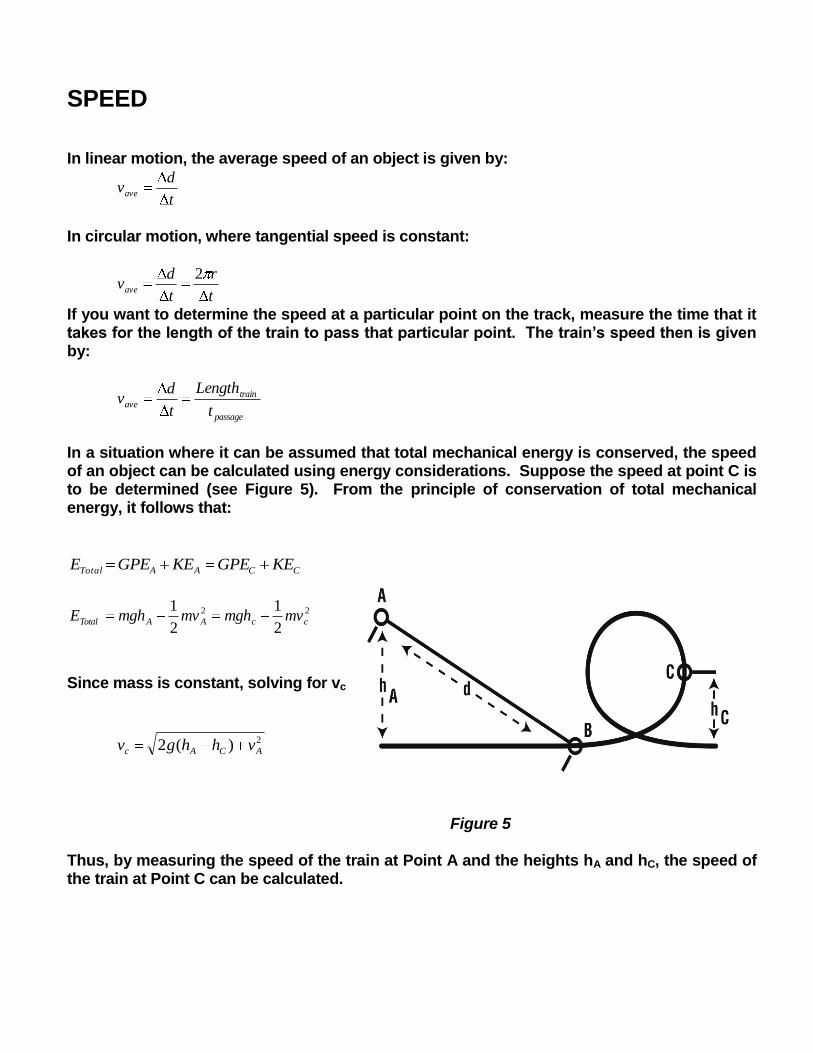
In a situation where it can be assumed that total mechanical energy is conserved, the speed of an object can be calculated using energy considerations. Suppose the speed at point C is to be determined (see Figure 5). From the principle of conservation of total mechanical energy, it follows that:
CCAATotal KEGPEKEGPEE
22
2
1
2
1ccAATotal mvmghmvmghE
Since mass is constant, solving for vc
2)(2 ACAc vhhgv
Figure 5 Thus, by measuring the speed of the train at Point A and the heights hA and hC, the speed of the train at Point C can be calculated.
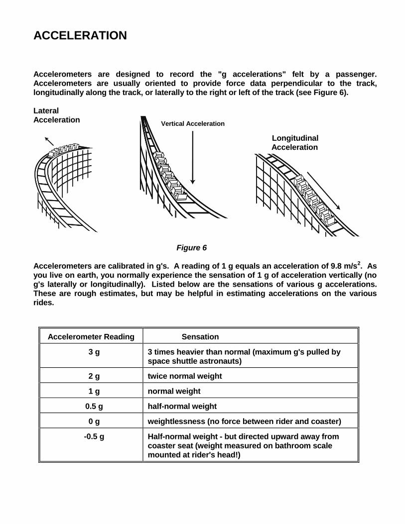
ACCELERATION Accelerometers are designed to record the "g accelerations" felt by a passenger. Accelerometers are usually oriented to provide force data perpendicular to the track, longitudinally along the track, or laterally to the right or left of the track (see Figure 6). Lateral Acceleration Longitudinal Acceleration Figure 6 Accelerometers are calibrated in g's. A reading of 1 g equals an acceleration of 9.8 m/s2. As you live on earth, you normally experience the sensation of 1 g of acceleration vertically (no g's laterally or longitudinally). Listed below are the sensations of various g accelerations. These are rough estimates, but may be helpful in estimating accelerations on the various rides.
Accelerometer Reading Sensation
3 g 3 times heavier than normal (maximum g's pulled by space shuttle astronauts)
2 g twice normal weight
1 g normal weight
0.5 g half-normal weight
0 g weightlessness (no force between rider and coaster)
-0.5 g Half-normal weight - but directed upward away from coaster seat (weight measured on bathroom scale mounted at rider's head!)
Vertical Acceleration
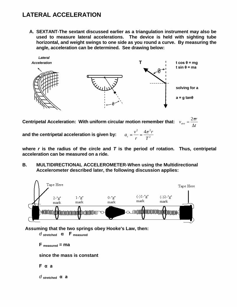
LATERAL ACCELERATION
A. SEXTANT-The sextant discussed earlier as a triangulation instrument may also be used to measure lateral accelerations. The device is held with sighting tube horizontal, and weight swings to one side as you round a curve. By measuring the angle, acceleration can be determined. See drawing below:
Lateral
Acceleration T T t cos θ = mg
t sin θ = ma
solving for a
a = g tanθ
Centripetal Acceleration: With uniform circular motion remember that: t
rvave
2
and the centripetal acceleration is given by: 2
22 4
T
r
r
vac
where r is the radius of the circle and T is the period of rotation. Thus, centripetal acceleration can be measured on a ride. B. MULTIDIRECTIONAL ACCELEROMETER-When using the Multidirectional
Accelerometer described later, the following discussion applies:
Assuming that the two springs obey Hooke's Law, then: d stretched α F measured F measured = ma since the mass is constant F α a d stretched α a
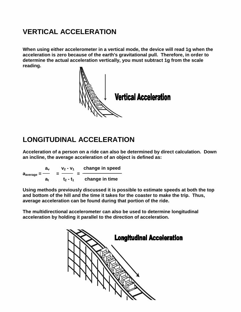
VERTICAL ACCELERATION When using either accelerometer in a vertical mode, the device will read 1g when the acceleration is zero because of the earth's gravitational pull. Therefore, in order to determine the actual acceleration vertically, you must subtract 1g from the scale reading.
LONGITUDINAL ACCELERATION Acceleration of a person on a ride can also be determined by direct calculation. Down an incline, the average acceleration of an object is defined as: av v2 - v1 change in speed aaverage = = = ______________________ at t2 - t1 change in time Using methods previously discussed it is possible to estimate speeds at both the top and bottom of the hill and the time it takes for the coaster to make the trip. Thus, average acceleration can be found during that portion of the ride. The multidirectional accelerometer can also be used to determine longitudinal acceleration by holding it parallel to the direction of acceleration.
WHAT: Double-racing out and back wooden roller coaster WHEN: May, 1981 WHERE: Six Flags Great America, Gurnee, IL DESIGNED & CONSTRUCTED BY: Figley-Wright Contractors, Inc. for Intamin, Inc. COLOR: White structure/blue track/red handrails TRACK LENGTH: 4,650 feet per track/9,300 feet of track NUMBER OF TRAINS: 4 NUMBER OF CARS: 4 cars per train NUMBER OF PASSENGERS: 30 passengers per train NUMBER OF GUESTS PER HOUR: Estimated 1,800 GREATEST HEIGHT: 127 feet (first incline) LENGTH OF FIRST VERTICAL LOOP: 147 feet ANGLE OF FIRST DROP: 55 Degrees LENGTH OF FIRST LIFT: 330 Feet (Chain speed: 9 feet per second) MAXIMUM SPEED: 66.32 miles per hour LENGTH OF RIDE: Estimated at 2:23 ACCELERATIONS: Do not exceed 1.65 g's in the dips OTHER INTERESTING FACTS: - 2,000 concrete footings (average of 18" in
diameter, 4.5 feet in depth)
- 1,360,000 board feet of lumber used
- 129,720 bolts
- 30,600 pounds of nails (15-16 tons)
- over 20,000 man hours to build
WHAT: Suspended Outside Looping Thrill Ride! WHEN: Debuted May 9, 1992 WHERE: Six Flag Great America Gurnee, Illinois DESIGNED AND Bolliger and Mabillard Monthey, FABRICATED BY: Switzerland COLOR: Bat Blue Track/Dark Purple and Yellow Cars TRACK LENGTH: 2,700 feet NUMBER OF TRAINS: 2 trains NUMBER OF CARS: 8 cars per train NUMBER OF PASSENGERS: 32 passengers per train GREATEST HEIGHT: 100 feet MAXIMUM SPEED: 50 miles per hour HEIGHT OF FIRST 77 feet VERTICAL LOOP: LENGTH OF RIDE: Estimated, 2 Minutes SPECIAL FEATURES: Outside looping, suspended high-speed chairlift-
type vehicles, "heart-line spin" at zero g.
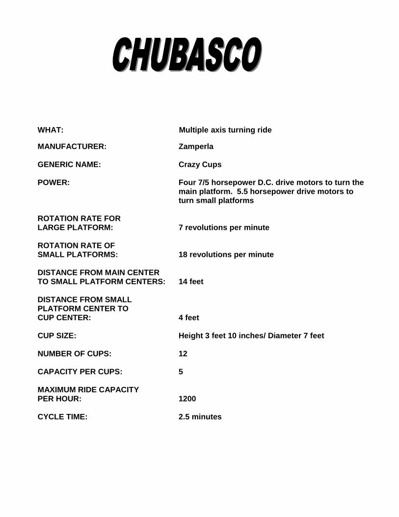
WHAT: Multiple axis turning ride
MANUFACTURER: Zamperla GENERIC NAME: Crazy Cups POWER: Four 7/5 horsepower D.C. drive motors to turn the
main platform. 5.5 horsepower drive motors to turn small platforms
ROTATION RATE FOR LARGE PLATFORM: 7 revolutions per minute ROTATION RATE OF SMALL PLATFORMS: 18 revolutions per minute DISTANCE FROM MAIN CENTER TO SMALL PLATFORM CENTERS: 14 feet DISTANCE FROM SMALL PLATFORM CENTER TO CUP CENTER: 4 feet CUP SIZE: Height 3 feet 10 inches/ Diameter 7 feet NUMBER OF CUPS: 12 CAPACITY PER CUPS: 5 MAXIMUM RIDE CAPACITY PER HOUR: 1200 CYCLE TIME: 2.5 minutes
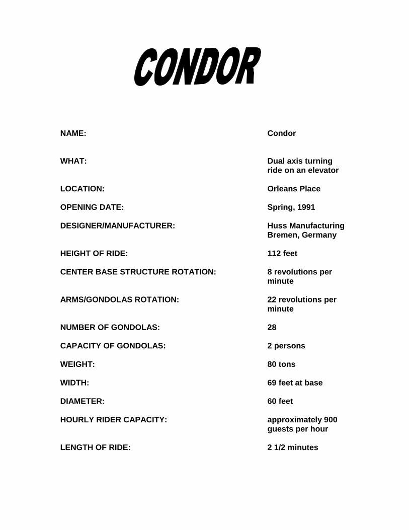
NAME: Condor WHAT: Dual axis turning
ride on an elevator LOCATION: Orleans Place OPENING DATE: Spring, 1991 DESIGNER/MANUFACTURER: Huss Manufacturing
Bremen, Germany HEIGHT OF RIDE: 112 feet CENTER BASE STRUCTURE ROTATION: 8 revolutions per
minute ARMS/GONDOLAS ROTATION: 22 revolutions per
minute NUMBER OF GONDOLAS: 28 CAPACITY OF GONDOLAS: 2 persons WEIGHT: 80 tons WIDTH: 69 feet at base DIAMETER: 60 feet HOURLY RIDER CAPACITY: approximately 900
guests per hour LENGTH OF RIDE: 2 1/2 minutes
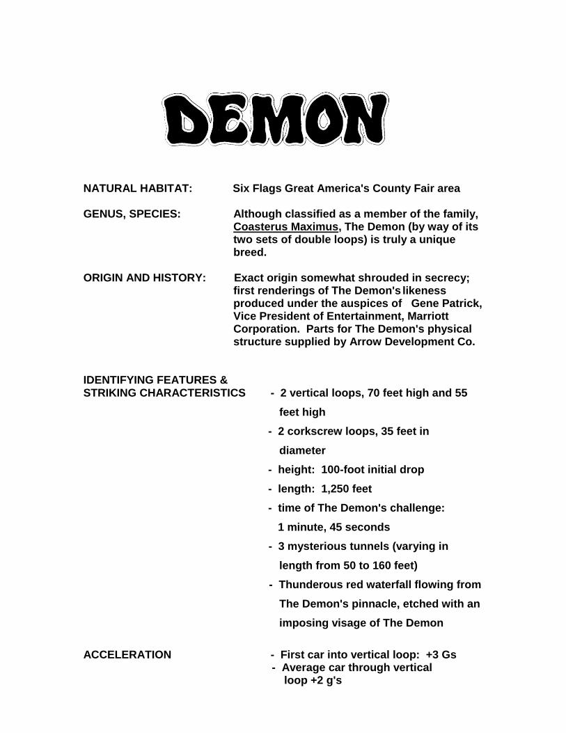
NATURAL HABITAT: Six Flags Great America's County Fair area GENUS, SPECIES: Although classified as a member of the family,
Coasterus Maximus, The Demon (by way of its two sets of double loops) is truly a unique breed.
ORIGIN AND HISTORY: Exact origin somewhat shrouded in secrecy;
first renderings of The Demon's likeness produced under the auspices of Gene Patrick, Vice President of Entertainment, Marriott Corporation. Parts for The Demon's physical structure supplied by Arrow Development Co.
IDENTIFYING FEATURES & STRIKING CHARACTERISTICS - 2 vertical loops, 70 feet high and 55
feet high
- 2 corkscrew loops, 35 feet in
diameter
- height: 100-foot initial drop
- length: 1,250 feet
- time of The Demon's challenge:
1 minute, 45 seconds
- 3 mysterious tunnels (varying in
length from 50 to 160 feet)
- Thunderous red waterfall flowing from
The Demon's pinnacle, etched with an
imposing visage of The Demon
ACCELERATION - First car into vertical loop: +3 Gs - Average car through vertical loop +2 g's
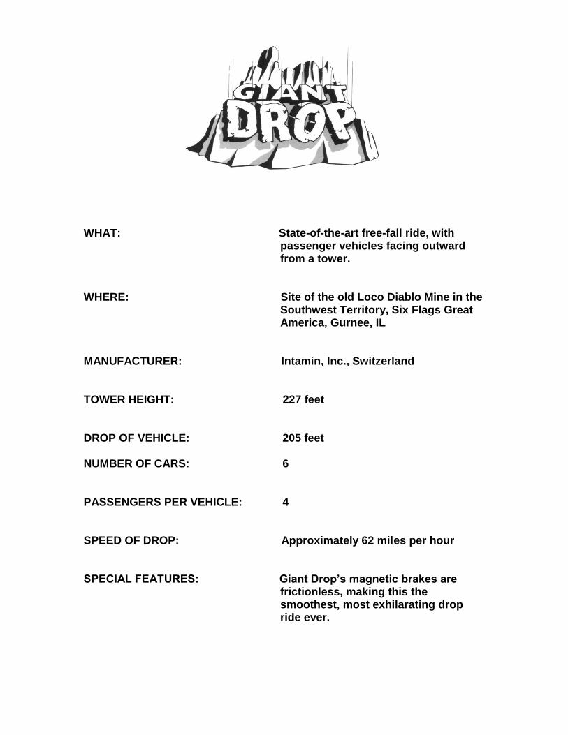
WHAT: State-of-the-art free-fall ride, with passenger vehicles facing outward from a tower.
WHERE: Site of the old Loco Diablo Mine in the
Southwest Territory, Six Flags Great America, Gurnee, IL
MANUFACTURER: Intamin, Inc., Switzerland TOWER HEIGHT: 227 feet DROP OF VEHICLE: 205 feet NUMBER OF CARS: 6 PASSENGERS PER VEHICLE: 4 SPEED OF DROP: Approximately 62 miles per hour SPECIAL FEATURES: Giant Drop’s magnetic brakes are
frictionless, making this the smoothest, most exhilarating drop ride ever.
INDUSTRY NAME OF RIDE: Scrambler® WHAT: Dual axis turning ride RIDE MANUFACTURER: Eli Bridge Company YEAR INTRODUCED AT THE PARK: 1976 RIDE CAPACITY: 12 cars, 2 or 3 seats per car A series of high-speed accelerations are the rule (not the exception) in this
exciting ride. This thrill ride consists of three arms of four cars, each
capable of holding three Guests.
Seated Guests ride through a star-shaped pattern at speeds up to 25 miles
per hour. The bench-like seats the riders sit on accelerate as they pass the
center spot of the star and stop when they reach the star’s perimeter. The
“sure” collision of cars is fortunately averted at the last moment.
KING CHAOS
INDUSTRY NAME OF RIDE: Top Spin RIDE MANUFACTURER: Huss YEAR INTRODUCED TO THE PARK: May 2004 NUMBER OF PASSENGERS: 1 gondola, 40 seats NUMBER OF PASSENGERS PER HOUR: 800 MAX HEIGHT: 18 meters SPECIAL FEATURES: This ride features very high
gravity-induced accelerations of up to 4 Gs! It performs vertical circular and swinging movements with exciting loopings within a very small space.
INDUSTRY NAME OF RIDE: Enterprise RIDE MANUFACTURER: Anton Schwarskopf YEAR INTRODUCED AT THE PARK: 1976 RIDE CAPACITY: 21 cabins, 2 seats per cabin A real white knuckler…this thrill ride spins the more daring Guests completely
upside down. When all the riders have been seated and all 21 of the rides’
cabin doors have been tightly secured, the ride begins to turn in a circle.
As the cabins whirl faster and faster, they begin to tilt outward and the entire
ride begins to lift. At the critical “thrill point” the ride attains a vertical position
and the cabins swing in a vertical plane…twirling the cabin occupants
completely upside down. Each cabin is capable of accommodating two
passengers.
WHAT: Steel “hyper-twister” roller coaster, featuring speeds exceeding 70 miles per hour, steep drops and high-banked turns. Out and back with a figure eight finish.
WHEN: Debuted May 1999 WHERE: Ride traverses the entire length of the
Southwest Territory at Six Flags Great America, Gurnee, Illinois – paralleling the guest parking lot and reaching from the Viper queue line to the Stunt Show Arena.
DESIGNED Bolliger and Mabillard AND FABRICATED BY: Monthey, Switzerland COLORS: Wine-colored support structures with orange
track; bright teal, red and yellow trains feature a bovine print motif and bull’s horns
TRACK LENGTH: 5,057 feet NUMBER OF TRAINS: 3 trains NUMBER OF CARS/PASSENGERS: 9 cars and 36 riders per train NUMBER OF PASSENGERS per HOUR: 1,560 LENGTH OF FIRST DROP: 200 feet (into an underground tunnel) at 65
degrees MAXIMUM SPEED: 73 miles per hour LENGTH OF RIDE: estimated, 2½ minutes SPECIAL FEATURES: Riders are secured in unique, open-sided cars
by a simple lap bar restraint. This high-speed roller coaster features 6 steep-banked turns and “inclined loops.”
INDUSTRY NAME OF RIDE: Frisbee RIDE MANUFACTURER: Huss YEAR INTRODUCED TO PARK: May 2004 NUMBER OF PASSENGERS: 40 persons/ 1 gondola NUMBER OF PASSENGERS PER HOUR: 800 HEIGHT OF GONDOLA IN FULL SWING: 19 meters MAX SWING ANGLE: +/- 85 degrees MAX PENDULUM SPEED: 50 km/h MAX PASSENGER SPEED: 81 km/h SPECIAL FEATURES: Passengers experience force
of up to 4 Gs with sensational giant swing movements with thrilling spins. The gondola swings up to 27 meters up to the horizontal position with moments of weightlessness for all passengers!
MANUFACTURER: Zamperla GENERIC NAME: Galleon 42 MAXIMUM SWING ANGLE: 170 degrees LENGTH OF BOAT: 30 feet NUMBER OF SEATS: 10 CAPACITY OF BOAT: 42 MAXIMUM CAPACITY PER HOUR: 1200 ACCELERATION: 0.4 g ACCELERATION: 1.4 g HORSEPOWER OF SWING MOTOR: 70 horsepower DC drive MAXIMUM SPEED: 28 miles per hour RIDE HEIGHT: 36 feet
Roaring Rapids WHAT: River Rapids Ride Water roller coaster WHERE: Orleans Place, Six Flags Great America, Gurnee, Illinois CONCEPTUAL DESIGN: Six Flag’s Great America and Intamin, AG, Zurich, Switzerland RIDE EQUIPMENT DESIGNED AND FURNISHED BY: Intamin, AG, Zurich, Switzerland RIDE ACREAGE: 3 acres CONCRETE: 3,000 cubic yards ARCHITECTURAL CONSULTANTS: Bleck and Associates, Waukegan, Illinois LANDSCAPE ARCHITECT: Dave McCallum, Libertyville, Illinois WORK BY: Arrow Landscaping, Gurnee, Illinois ROCKWORK DESIGNED AND Cost of Wisconsin, Inc., INSTALLED BY: Germantown, Wisconsin LENGTH OF RIDE: 1,500 feet - complete cycle RAPIDS: 3 Sets of rapids totaling 750 feet, longest set - 500 feet WIDTH OF RIVER: varies from 18 to 40 feet WATER GRADE: 12 feet from start to finish BOATS: Total: 20; capacity: 12 riders Size: 13.5 feet in diameter RIDE CAPACITY: Approximately 2,000 guests per hour LENGTH OF RIDE: Approximately 5 minutes
PAGE 2
ROARING RAPIDS CONTINUED
WATER PUMPS: 5 main pumps - 175 horsepower each 5 auxiliary pumps - 170 horsepower total WATER USAGE: Capacity: 1.2 million gallons with
180,000 gallons pumped per minute. All water for the ride will be recirculated.
BOAT PROPULSION: Boats are free-floating and propelled
only by the flow of the river. SPECIAL EFFECTS: 2 wave makers - 25 horsepower each One 120-foot tunnel with special light,
sound, and animated effects. 3 waterfall complexes HIGHLIGHTS: First River rapids ride in United States to
use a turntable loading station. Landscape artistically designed to
resemble Natural River using native grasses, wildflowers, and over 1,400 trees and shrubs.
INDUSTRY NAME OF RIDE: Tower RIDE MANUFACTURER: Intamin, Inc. YEAR INTRODUCED AT THE PARK: 1977 RIDE CAPACITY: 70 Guests climb aboard an escalating cabin that rotates a full 360 degrees as
it climbs 285 feet into Great America's skyline. The 70-seat cabin treks the
length of the tower at the leisurely pace of three miles per hour. The entire
height of Sky Trek Tower, from base to the top of the structure's flagpole, is
330 feet. The American Flag flown atop Sky Trek Tower Measures 20' x 38'
and is one of the area's largest. Guests will enjoy a dramatic aerial
excursion into the Illinois skyline with a spectacular view of the Park, Lake
Michigan and portions of the Chicago skyline.
DESCRIPTION: The Midwest’s most unique flying coaster, SUPERMAN
– Ultimate Flight, based on the DC Comics Super Hero, SUPERMAN, is the newest generation of roller coaster providing an unparalleled flying experience at speeds greater than 50 miles per hour.
OPENING DATE: Spring, 2003 MAXIMUM HEIGHT: 115 feet FIRST DROP: 109 feet RIDE ELEMENTS: 1 pretzel-shaped inverted loop 1 spiral 2 horseshoe curves 1 360-degree in-line roll RIDE FEATURES: A pretzel-shaped, inverted loop where trains climb to
the top of the figure and dive into the loop traveling amazingly close to the ground heightening the feeling of flying.
A sequence of thrilling curves and dives that includes a highly inclined “horseshoe” curve and high-speed spiral.
A 360-degree, in-line roll will surprise guests just before
entering the station. TRACK LENGTH: 2,798 feet of twisting, looping blue, red and yellow
steel RIDE TIME: Nearly 3 minutes VEHICLES: Two sleek trains specially designed to carry 32
passengers FLYING four abreast. SAFETY SYSTEMS: Computer controlled fail-safe brakes and padded
shoulder/breast harnesses and lap bars assure proper ride safety and comfort.
CAPACITY: 1,100 riders per hour MANUFACTURER: Bolliger & Mabillard of Monthey, Switzerland
WHAT: This impulse shuttle coaster utilizes a
unique motor system known as Linear Induction Motors or LIM for short. Using magnetics, the ski-lift style train is launched out of the loading station at skyrocketing speeds of 70 miles per hour.
WHEN: Spring 2001 WHERE: Across from Batman The Ride in Yankee
Harbor DESIGNED AND FABRICATED BY: Intamin COLORS: Blue support structures with yellow track TRACK LENGTH: 630 feet NUMBER OF TRAINS: 1 train NUMBER OF PASSENGERS: 28 riders per train HEIGHT OF TOWERS: Both are 185 feet (first tower will feature
spiraled-track) MAXIMUM SPEED: 70 miles per hour SPECIAL FEATURES: The U-shaped track and spiraled first tower
will take riders on a one-of-kind journey.
WHAT: A turning, twisting, classic figure-eight
wooden roller coaster that takes its riders on a thrill-a-second experience.
WHEN: Opened April 1995 WHERE: Six Flags Great America Gurnee, Illinois
TRACK LENGTH: 3,458 feet NUMBER OF TRAINS: 2 trains NUMBER OF CARS: 5 cars per train NUMBER OF PASSENGERS: 30 passengers per train PASSENGERS PER HOUR: 1,000 HEIGHT OF LIFT: 100 feet DEGREE OF FIRST DROP: 53 degrees LENGTH OF FIRST DROP: 80 feet APPROXIMATE SPEED: 50 miles per hour LENGTH OF RIDE: 1 minute, 45 seconds
DESCRIPTION: Steel roller coaster operating on
"g-acceleration" concept with a seven-story "free-fall" down a spiraling track; features 70-degree banked turns.
PREMIERED: May, 1976 WHERE: Six Flags Great America MAXIMUM HEIGHT: 70 feet MAXIMUM SPEED: 42 miles per hour LENGTH OF TRACK: 3,100 feet NUMBER OF TRAINS: Five trains NUMBER OF CARS: Four cars per train NUMBER OF PASSENGERS: 16 passengers per train NUMBER OF GUESTS PER HOUR: 1,920 guests per hour LENGTH OF RIDE: 2 minutes MANUFACTURER: Anton Schwarzkopf, West Germany
Trade Name: Wild Mouse Coaster Manufacturer: Mack Rides Date Installed: 2008 Speed (maximum): 30 m.p.h. Ride Length: 1,213 feet Height (maximum): 50 feet Ride Time: 2 minutes Number of Cars: 10 Number of Seats per Car: 4 MOD: 40 Capacity per hour: Up to 900 with maximum units Description of Motion: An exciting ride/attraction with sudden
turns and drops.
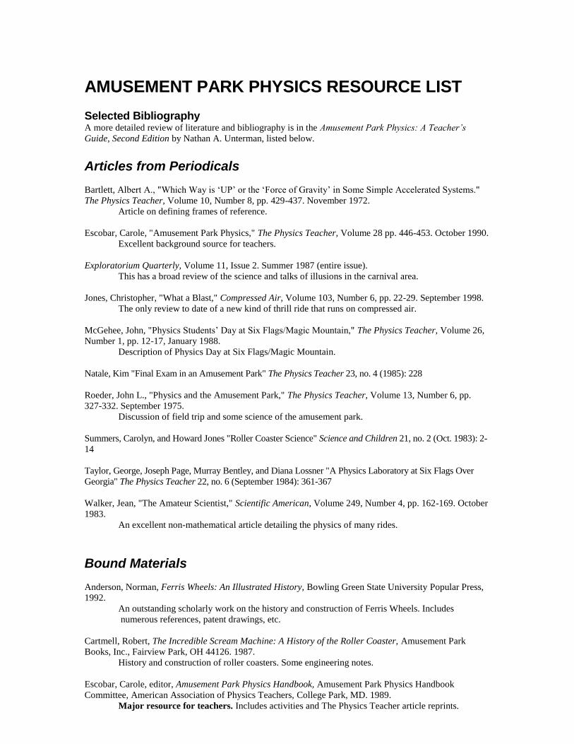
AMUSEMENT PARK PHYSICS RESOURCE LIST Selected Bibliography A more detailed review of literature and bibliography is in the Amusement Park Physics: A Teacher’s
Guide, Second Edition by Nathan A. Unterman, listed below.
Articles from Periodicals
Bartlett, Albert A., "Which Way is ‘UP’ or the ‘Force of Gravity’ in Some Simple Accelerated Systems."
The Physics Teacher, Volume 10, Number 8, pp. 429-437. November 1972.
Article on defining frames of reference.
Escobar, Carole, "Amusement Park Physics," The Physics Teacher, Volume 28 pp. 446-453. October 1990.
Excellent background source for teachers.
Exploratorium Quarterly, Volume 11, Issue 2. Summer 1987 (entire issue).
This has a broad review of the science and talks of illusions in the carnival area.
Jones, Christopher, "What a Blast," Compressed Air, Volume 103, Number 6, pp. 22-29. September 1998.
The only review to date of a new kind of thrill ride that runs on compressed air.
McGehee, John, "Physics Students’ Day at Six Flags/Magic Mountain," The Physics Teacher, Volume 26,
Number 1, pp. 12-17, January 1988.
Description of Physics Day at Six Flags/Magic Mountain.
Natale, Kim "Final Exam in an Amusement Park" The Physics Teacher 23, no. 4 (1985): 228
Roeder, John L., "Physics and the Amusement Park," The Physics Teacher, Volume 13, Number 6, pp.
327-332. September 1975.
Discussion of field trip and some science of the amusement park.
Summers, Carolyn, and Howard Jones "Roller Coaster Science" Science and Children 21, no. 2 (Oct. 1983): 2-
14
Taylor, George, Joseph Page, Murray Bentley, and Diana Lossner "A Physics Laboratory at Six Flags Over
Georgia" The Physics Teacher 22, no. 6 (September 1984): 361-367
Walker, Jean, "The Amateur Scientist," Scientific American, Volume 249, Number 4, pp. 162-169. October
1983.
An excellent non-mathematical article detailing the physics of many rides.
Bound Materials
Anderson, Norman, Ferris Wheels: An Illustrated History, Bowling Green State University Popular Press,
1992.
An outstanding scholarly work on the history and construction of Ferris Wheels. Includes
numerous references, patent drawings, etc.
Cartmell, Robert, The Incredible Scream Machine: A History of the Roller Coaster, Amusement Park
Books, Inc., Fairview Park, OH 44126. 1987.
History and construction of roller coasters. Some engineering notes.
Escobar, Carole, editor, Amusement Park Physics Handbook, Amusement Park Physics Handbook
Committee, American Association of Physics Teachers, College Park, MD. 1989.
Major resource for teachers. Includes activities and The Physics Teacher article reprints.
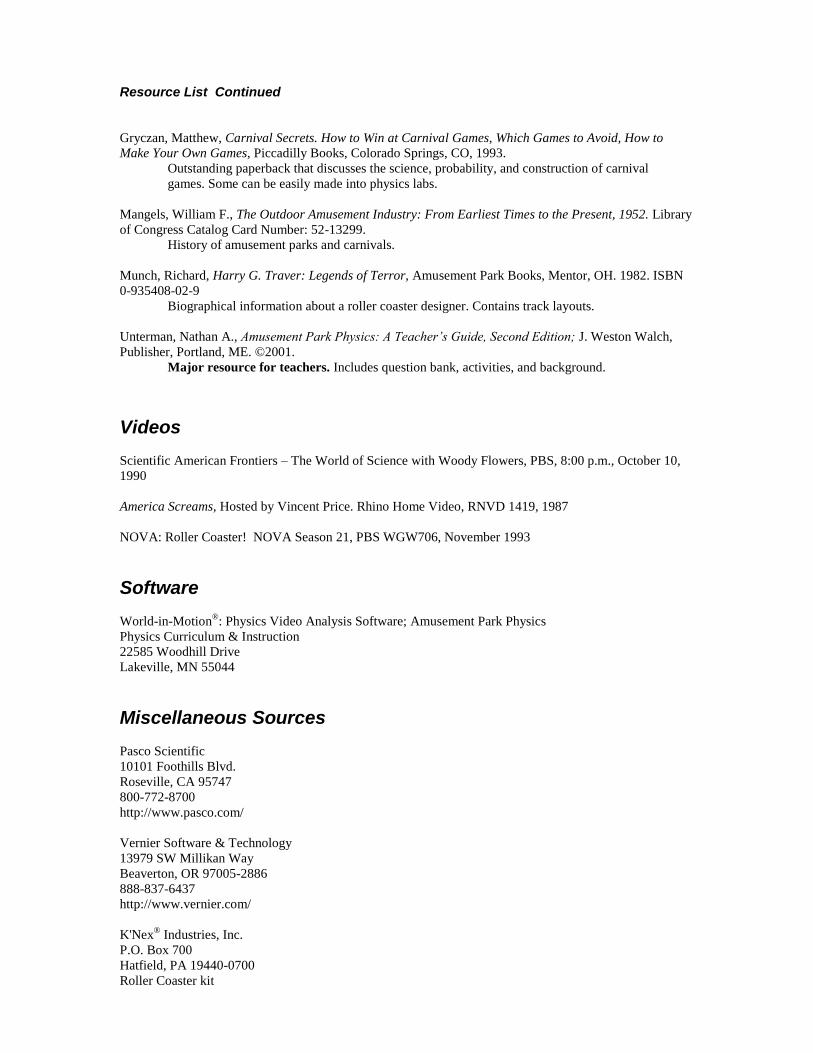
Resource List Continued
Gryczan, Matthew, Carnival Secrets. How to Win at Carnival Games, Which Games to Avoid, How to
Make Your Own Games, Piccadilly Books, Colorado Springs, CO, 1993.
Outstanding paperback that discusses the science, probability, and construction of carnival
games. Some can be easily made into physics labs.
Mangels, William F., The Outdoor Amusement Industry: From Earliest Times to the Present, 1952. Library
of Congress Catalog Card Number: 52-13299.
History of amusement parks and carnivals.
Munch, Richard, Harry G. Traver: Legends of Terror, Amusement Park Books, Mentor, OH. 1982. ISBN
0-935408-02-9
Biographical information about a roller coaster designer. Contains track layouts.
Unterman, Nathan A., Amusement Park Physics: A Teacher’s Guide, Second Edition; J. Weston Walch,
Publisher, Portland, ME. ©2001.
Major resource for teachers. Includes question bank, activities, and background.
Videos
Scientific American Frontiers – The World of Science with Woody Flowers, PBS, 8:00 p.m., October 10,
1990
America Screams, Hosted by Vincent Price. Rhino Home Video, RNVD 1419, 1987
NOVA: Roller Coaster! NOVA Season 21, PBS WGW706, November 1993
Software
World-in-Motion®: Physics Video Analysis Software; Amusement Park Physics
Physics Curriculum & Instruction
22585 Woodhill Drive
Lakeville, MN 55044
Miscellaneous Sources
Pasco Scientific
10101 Foothills Blvd.
Roseville, CA 95747
800-772-8700
http://www.pasco.com/
Vernier Software & Technology
13979 SW Millikan Way
Beaverton, OR 97005-2886
888-837-6437
http://www.vernier.com/
K'Nex® Industries, Inc.
P.O. Box 700
Hatfield, PA 19440-0700
Roller Coaster kit