Embed Size (px)
Citation preview
Physics. - Hyperboloïdical cooling towers. By F . K. TH. VAN ITERSON.
(Communicated at the meeting of January 26, 1946.)
Recourse is taken to cooling towers at industrial plants, mainly electricpower stations, wh ere river water in sufficient quantity is deficierit. Cooling. towers are used for transmitting the heat of the water to the atmosphere so that the water may circulate over and over again.
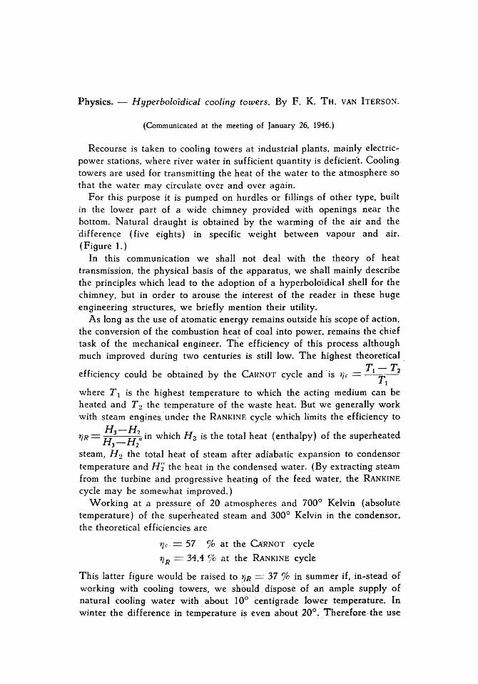
For this purpose it is pumped on hurdles or fillings of other type, built in the lower part of a wide chimney provided with openings near the bottom. Natural draught is obtained by the warming of the air and the ·difference (five eights) in specific weight between vapour and air. (Figure 1.)
In th is communication we shall not deal with the theory of heat transmission, the physical basis of the apparatus, we shall mainly describe the principles which lead to the adoption of a hyperboloïdical shell (or the chimney, but in order to arouse the interest of the reader in these huge engineering structures, we briefly mention their utility.
As long as the use of atomatic energy remains outside his scope of action , the conversion of the combustion heat of coal into power, remains the chief task of the mechanical engineer. The efficiency of th is process although much improved during two centuries is still low. The highest theoretical .
T-T efficiency could be obtained by the CARNOT cycle and 'is tJe = _ 1 ___ 2
TI where Tl is the highest temperature to which the acting medium can be heated and T 2 the temperature of the waste heat. But we generally work with steam enginesunder the RANKINE cycle which limits theefficiency to
H3-H " h ' h H ' th Ih (th I ) f th h t d 1]R = H H 11 m w IC 3 IS e tota eat en a py 0 e super ea e 3- 2
steam, H 2 the total heat of steam af ter adiabatic expansion to condensor temperature and H~ the heat in the condensed water. (By extracting steam from the turbine and progressive heating of the feed water, the RANKINE cycle may be somewhat improved. )
Working at a pressur~ of 20 atmospheres and 7000 Kelvin (absolute temperature) of the superheat'ed steam and 3000 Kelvin in the condensor. the theoretica I efficiencies are
1]e = 57 % at the CAJRNOT çycle
1]R = 34,4 ?o at the RANKINE cyde
This latter figure would be raised to fJR. = 37 % in summer if, in-stead of working with cooling towers, we should dispose of an ample supply of natural cooling ~ater with about 100 centigrade Iower temperature. IJ). winter the difference in temp~rature i~ even ah~ut .200 ~ · Therefore· the use
114
of cooting towers seems to be prejudicial. But in engineering practiee things are of ten complicated byevents of economie order. It is extremely costly to use steain of low temperature and the correspondirig high vacuum. IE we
VI!RTICAL .j~CT/ON
~eCTfONA-[j
Fig. 1.
"raIl DrtSUTTQ; NozzLr AH/} ('liP.
U
reach 20° C, in~stead as for instance 40° C , the volume of the steàin increases threefold and the density drops to one third. The economie consequences on the construction and running of the steam -turbine are:
1°. Some large turbine discs must be added to the low pressure part of the turbine. As the circuniferencial velocity of the turbine blades is prescribed by the criterium of 'safety, the result is, that at a given weight and floor space a greater output can be obtained with warm cooting water thari with cold: a rather paradoxical àchievement.
20.. the largest turbine parts, riamèly exhaust connection and
115
condensor are much reduced in si ze when cooling towers are used. The feed water is warmer.
30. Mechanical efficiency is improved and blade erosion much lessened. However. the use of cold cooling water remains an advantage. IE possible
larg:e electric power stations ought to be errected at lake-sides. iiver or canal banks. In summer the water tempera tu re may then he about 25° C in stead of 35° to 40° with cooling towers. In practice with cooling towers the steam and coal consumption are about 2 % higher and it depends on factors of quite another magnitude whether preponderance must be given to a dry site for the erection of a ('ower plant. Cheap supply of Iuel as on coal or lignite fields and better and cheaper building space are of.ten decisive. Experience in England. for instance Ham' s Hall Power Station near Birmingham. has shown that electricity with cooling towers may be produced at the same price or çheaper than with natural water. This has been realized by our invention. Formerly cooling towers were built from timber. This is not only more expensive than concrete. but the cooling effect suffers by leakage and warping. In consequence of putrification many cooling towers were destroyed by a ga Ie within 15 years af ter their erection. The conditions of humidity and warm th to which these structures are subjected are most deleterious to their preservation. Ouring the many and long periods of inaction for repairs the enormous risk of an unextinguishable fire was so prominent that for th is reason alone the application had to be excluded.
We shall now deal with the incentives which led to the construction of the unifoil concrete cooling towers. which in the first place were invented on behalf of the exigencies prevailing at the Outch State Mines. where . the building site is subjected to subsidences. Notwithstanding the preservation of a substantial shaftssafety pillar. the possibility of an irregular subsidence of the surface near the coal pits had to be taken into account.
From experience and theoretical investigations on gasholder frames and other th ree dimensional frame-work we 'were aware that mantlelike frames open at the top may follow uneven subsidences of their foundation and we soon were conscious that the same freedom of coactions exists in thin walled unifoil structures open at the top. as we had long ago demonstrated with gasholder tanks.
We experimented with papfr and tin-plate models and found our prediction confirmed. In our days of thorough investigation into the strength of unifoil aeroplane wings th is d~formability has become common knowledge. We read 'in FLÜGGE. Statik uod Dynamik der Séhalen p. 56: "is the shell open at its top. then we may prescribe two of the displacements 11 . v and w at one edge. or one at each edge (u is the component of displacement alo09 a circle of latitude .. v along a meridian arid w the displacement normal to the shell).
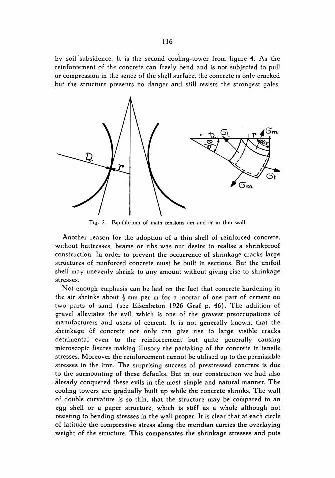
'f.hat our assumptions were justified has been proved in a remarkable manner. Figure 3 shows acooling tower at mine Emma severely deformed
116
by soilsubsidence. It is the second cooling-tower from figure 4. As the reinforcement of the concrete can 'freely bend and is not subjected to pull or compression in the sence of the sh~U surface. the concrete is only cracked but the structure presents no danger and still resists the strongest gales.
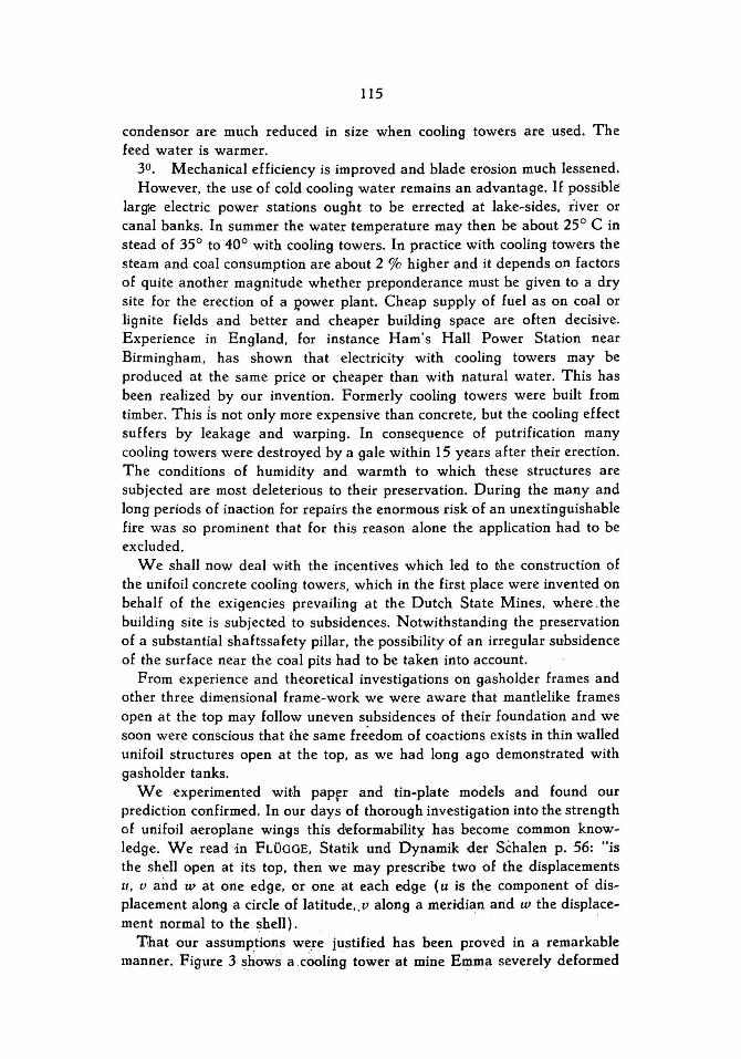
Fig . 2. Equilib,ium of main tensions om and ot in thin wall.
Another reason for the adoption of a thin shell of reinforced concrete. without buttresses. beams or ribs was our desire to realise a shrinkproof construction. In order to prevent the occurrence óf· shrinkage cracks large structur,es of reinforced concrete must be built in sections. But the unifoil sheIi may unevenly shrink to any amount without giving rise to shrinkage stresses.
Not enough emphasis can be iaid on the fact that concrete hardening in the air shrinks about -! mm per m for a mortar of one part of cement on two parts of sand (see Eisenbeto~ 1926 Graf p. 46). The addition of gravel alleviates the evil . whiCh is one of the gravest preoccupations of manufacturers and users of cement. It is not generally known. that the shrinkage Of concrete not pnly can give rise to large visible cracks detrimental even to the reinforcement but ' quite generally causing microscopic fisures making illusory the partaking of the concrete in tensile stresses. Moreover the relnforcement cannot be utilised up to the permissible stresses in the iron. The surprising success of prestr'essed concrete is due , to the surmounting of these defaults. But in our construction we had also àlready conquered theseevils in tlie most simple and natural manner. The cooling towers are gradually built up while the concrete shrinks. The wall of double curvature is ~o thin. that the structure may be compared to an egg shell or a paper structure. whichis stiEf as a whole although n'ot resisting to bending stresses in the wall proper. It is dear that at each cirde of latitude the compressive stress aiong the meridian carries the overlayiftg weight of the structure. This compensates the shi.-inkage stresses and puts
F. K. TH. VAN ITEHSON: Hyperbalaïdical coaling tawers.
Fig. 3. Cooling tower at coal-pit Emma deformed by soil subsidence.
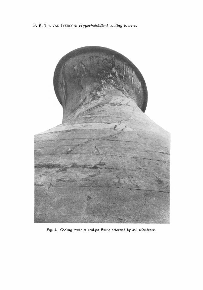
Fig. 4. The second cooling tower has been deformed to the shape represented in fig. 3,
117
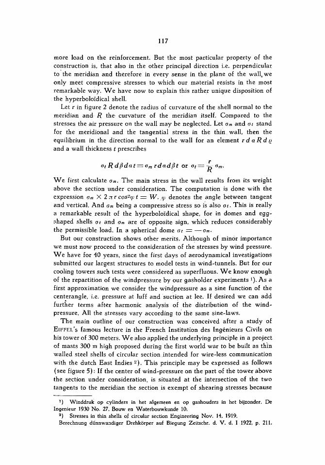
more load on the reinforcement. But the most particular property of the construct ion is, that also in the other principal direction i.e. perpendiculaI: to· the meridian and therefore in every sen se in the plane of the wall, we only meet compressive stress es to which our material resists in the most remarkable way. We have now to explain this rather unique disposition of the hyperboloïdical shell.
Let r in figure 2 denote the radius of curvature of the shell norm al to the meridian and R the· curvature of the meridian itself. Compared to the stresses the air pressure on the wall may be neglected. Let Om and Ot stand for the meridional and the tangential stress in the thjn . wall, then the equilibrium in the direction normal to the wall for an element r daR d e and a wall thickness t prescribes
r OtRdfJdat=omrdadfJt or Ot= ROm.
We first calculate Om. The main stress in the wall results from its weight above the section under consideration. The computation is done with the expres sion Om X 2:n r cos2q; t = W.q; denotes the angle between tangent and vertical. And 0 m being a compressive stress so is also 0 t. This is really a remarkable result of the hyperboloïdical shape, for in domes and eggr.haped shells Ot and Om are of opposite sign, which reduces considerably the permissible load. In a sphericaldome Ot = -Om.
But our construction shows other merits. Although of minor importance we must now proceed to the consideration of the stress es by wind pressure. We have for 40 years, since the first days of aerodynamical investigations submitted our largest structures to model tests in wind-tunnels. But for our cooling towers such tests were considered as superfluous. W ·e know enough of the repartition of the windpressure by our gasholder experiments 1). As a first approximatiQn we consider the windpressure as a sine function of the centerangle, i.e. pressure at luff and suction at lee. If desired we can add further terms af ter harmonic analysis of the distribution of the windpressure. All the stresses vary according t~· the same sine-laws.
The main outline of our construction was conceived af ter a study of EIFFEL's famous lecture in the French Institution des Ingénieurs Civils on his tower of 300 meters . We also applied the underlying principle in a project of masts 300 m high proposed during the first world war to be built as thin walled steel shells of circular section jntended for wire-less communication with the dutch East Indies 2). This principle may be expressed as follows (see figure 5): If the center of wind-pressure on the part of the tower above the section under consideration, is situated at die intersection of the two tangents to the meridian the section is exempt of shearing stress es because
1) Winddruk op cylinders in het algemeen en op gashouders in het bijzonder. De Ingenieur 1930 No. 27. Bouwen Waterbouwkunde 1(}'
2) Stresses in th in shells of circular section Engineering Nov. 14. 1919. Berechnung diinnwa:1diger Drehkörper auf Biegung Zeitschr. d. V. d. I 1922. p. 211.
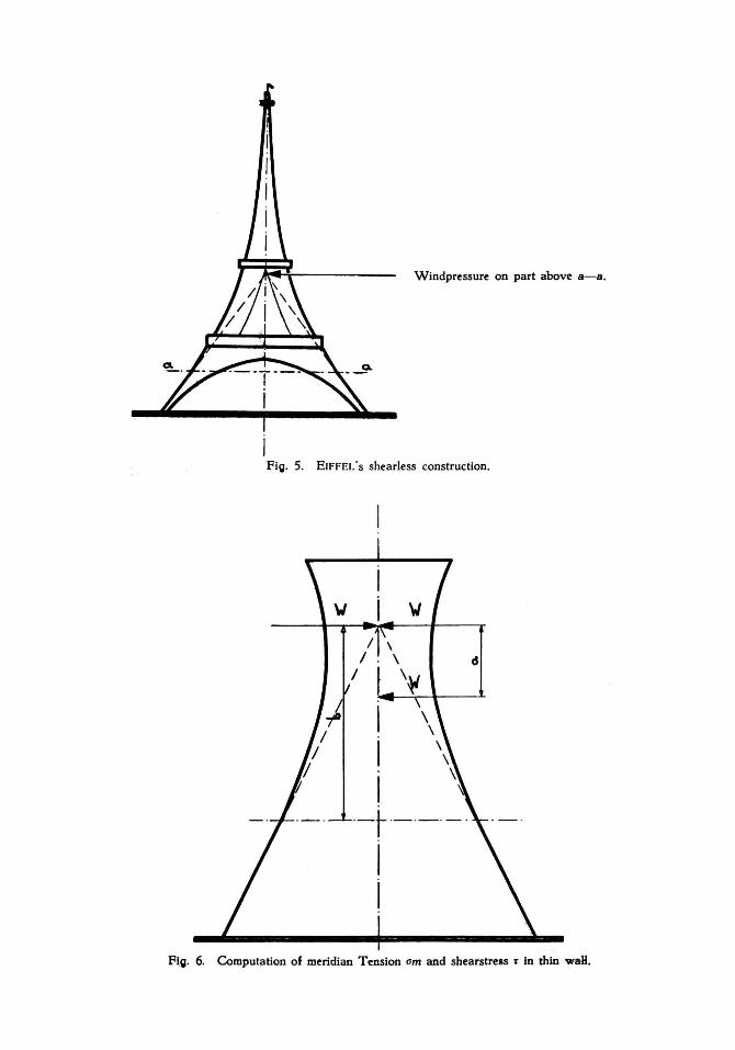
Windpressure on part above a-a.
Fig. 5. EIFFEL's shearless construction.
I I I
--t--- -- -- -I I
Fig. 6. Comput!!tion of meridian Tension om and shearstrels T in thin waH.
119
all the meridional stresses act in this point ofintersection. In the case of figure 6 representing our cooling tower the conditions are only slightly different.
The center of windpressure W is in the under part of the tower a small distance a lower than the point of intersection of the tangents. With the notations given in the figure we have to calculate with the horizontal force
W ( 1 -~) acting in the point of intersection and with the shearing force
a W b acting in the section under consideration. The lower part of the shell
is by far the most ponderous. Here a is almost equal to b, so that the shearing stress es are negligible. But also the circumference and the wall thickness are such that the meridional stress es which counteract the
horizontal force W (1 -~) are very smal!. The meridional compressive
stresses due t~ the weight are the only charg'es of some importance. But as already mentioned, reinforced concrete, especially that which is built up under a growing load and compressed in both main directions is very resistant to this kind of stress. The result of the accurate streng th computation of our cooling towers is that our aim is overreached. For practical reasons we cannot make the shell th in enough to make full use of the strength of the chosen material of construction. Mr. CHR. GROOTHOFF,
civil engineer of the State Mines, who took a great part in the development of our cooling towers suggested to build the th in shell of masonry, and indeed this would be possible. The reason which withheld us from executing this proposition was our fear of deterioration by frost of our somewhat porous brickwork always thoroughly wetted by a continual jnternal shower.
With re gard to the foregoing remark we must mention a peculiar consequence of the laws of similitude applied to cooling towers. At comformable enlargement of the structure the stresses due to windpressure, both tension élnd . compression stresses remain the same. The far more important com': pression stresses due to weight increase in proportion to the height of the cooling tower but are independent of wall thickness and even for the highest towers they remain smalI. The higher these stresses are the bet ter. The largest cooling towers, several of which have been built (1) have a capacity of 5 million gallons = 22,500 m3/h, height 320 ft = 98 m, diameter at ground level 220 ft = 67 m. These apparatus are the best in every respect and a further enlargement will be profitable. The reason for this is th at the wall-thickness needs not to increase conformably and the larger units are the cheapest per million of gallons of circulation. The choice of the wall-thickness is a matter of experience. The reinforcement is only wanted in order to prevent cracking due to local irregularities in shrinkage.
1) Engi::leering, Febr. 1, 19i6, p. 97.
120
For a full understanding of the conditions to which the concrete shell is subjected, we must also pay some attention to temperature stresses. Although considered as a whole the unifoil is free of such stresses which property may be considered as its chief merit; so that it may be exposed to frost at the shadowed side and be more than handwarm on the sunny si de, there are conditions for which the temperature stresses must be taken into account.
When during a severe frost the air openings become partly clogged by ice, temperature differences of the order of 30° may arise between inner~ and outer surface of the wall. But the state of compression reigning in the wall is extremely beneficia 1 in this case and it is a fact that the cost of upkeep during a quarter of a century has been nil for concrete towers.
We have hardly to mention that the reinforcement of the concrete consists of straight bars placed .according to the descriptive lines of the hyperbaloïd. Ouring erection the exact shape of the shell is simply controlled by a string.
The buckling strength of cylindrical chimneys can be chequed by computation, but this theory has hitherto not been extended to double curved shells. Although rather superfluous, we took the precaution of experimenting the streng th to buckling by a tin plate model, nailed to a timber scaffold and loaded by means of a strong string round its neck.
We could not produce any deflection under a load surpassing largely the highest possible buckling pressure equivalent to wind load.
The hyperboloïdical shape, the smoothness of the interior, the absence of crossbeams prevail in the performance of the apparatus. Every aerodynamical expert will acknowledge that we have realised the conditions for potentical flow, i.e. , thestreamlines converge and diverge evenly. The thoroughHow in the stack is free from eddies and vortexes, there is no loss of energy.
The external smoothness reduces the windpressure to less than a half of what it should be on a cooling tower of the usual rectangular sec ti on and the same vertical area of projection.
As these largestructures would predominate in the silhouette of the industrial plants for which they are intended, attention had to be paid to their becoming appeatance. Our aesthetical expert , the architectural engineer W . F. FONTEIN, had to make perspective sketches of our projected power stations and everybody was pleased by the prospect. We came to the conclusion that large but simple mathematically shaped bodies like pyramids, spheres, cones; hyperboloïds give satisfaction to: the eye.To day hundreds of these towers built on an ever increasing scale are erected all ove~ the world ' and are generally admired. In our mining district they became an emblem of the industry.
Wh en the idea of constructing these simple shells free tö contractand to deform in case of subsidence was first presented for execution, the prominent contractors of reinforced concrete works refused ta tèhder. They
121
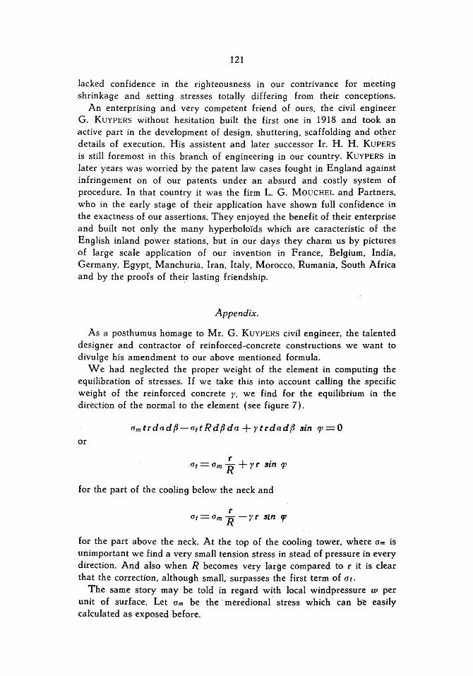
lacked confidence in the righteousness iJl our contrivance for meeting shrinkage and setting stress es totally differing from their conceptions.
An enterprising and very competent friend of ours. the civil engineer G . KUVPERS without hesitation built the first one in 1918 and took an active part in the development of design. shuttering . scaffolding and other details ofexecution. His assistent and later successor Ir. H. H . KUPERS is still foremost in th is branch of engineering in our country. KUYPERS in later years was worried by the patent law cases fought in England against infringement on of our patents under an absurd and costly system of procedure. In that country it was the firm L. G . MO UCHEL and Partners. who in the early stage of their application have shown full confidence in the exactness of our assertions. They enjoyed the benefit of their enterprise and built not only the many hyperboloïds which are caracteristic of the English inland power stations. but in our days they charm us by pictures of large scale application of our invention in France. Belgium. India. Germany. Egypt. Manchuria . Iran. Italy. Morocco. Rumania. South Africa and by the proofs of their lasting friendship .
Appendix.
As a posthumus homage to Mr. G . KUYPERS civil engineer. the talented designer and contractor of reinforced~concrete constructions we want to divulge his amendment to our above mentioned formula .
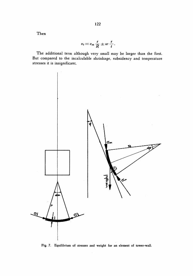
We had neglected the proper weight of the element in computing the equilibration of stresses. If we take this into account calling the specific weight of the reinforced concrete r. we find for the equilibrium in the direction of the normal to the element (see figure 7).
am trdadf3-attRdf3da + rtrdadf3 sin 91=0 or
r + . at = am R r r sm 91
for the part of the cooling bclow the neck and
for the part above the neck. At the top of the cooling tower. where am is unimportant we find a very small tension stress in stead of pressure in every direction. And also when R becomes very large compared to r it is clear that the correction. although smalt surpasses the first term of Ot.
The same story may be told in regard with local windpressure w per unit of surface. Let Om be the ' merédional stress which · can bie easily calculated as exposed before.
122
Then
t' t' Gt=Gm R ±wT'
The additional term although very small may he larger than the first, But compared to the incalculahle shrinkage. subsidency and temperature stress es it is insignificant.
Fig, . 7. Equilibrium of stresses and weight for an element of tower-wall.

![AMOS Business Suite Basics Peter van Mossevelde [April 14 th 2005] AMOS Maintenance & Purchase](https://img.pdfslide.us/doc/110x75/56649e0d5503460f94af6f04/amos-business-suite-basics-peter-van-mossevelde-april-14-th-2005-amos-maintenance.jpg)