Embed Size (px)
Citation preview
Physics 2210 Fall 2015
smartPhysics 16 Rotational Dynamics
17 Rotational Statics 11/16/2015
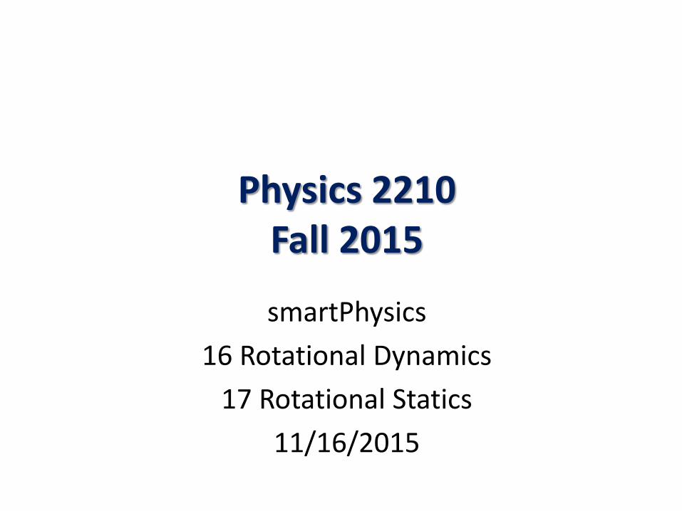
Example 16.1 (3/4) A round “wheel” of mass 𝑀, radius 𝑅 and 𝑰𝑪𝑪 = 𝜸𝑪𝑹𝟐 (0 < 𝛾 < 1) rolls without slipping down an incline at angle 𝜙 from the horizontal. Find the linear acceleration of the wheel down the incline.
Alternate Solution: Let +x be down slope and +y point perpendicularly out of the incline. We will chose CCW As the positive rotation sense. For rolling without slipping then we have:
𝑣𝑥 = −𝑅𝜔, 𝑎𝑥 = −𝑅𝑅 Where𝑣𝑥 and 𝑎𝑥 are the velocity and acceleration components down slope. Applying Newton’s Second Law on the CM, first in the y-direction
𝑀𝑎𝑦 = 𝑁 −𝑀𝑀 cos𝜙 = 0 → 𝑁 = 𝑀𝑀 cos𝜙 Which is not really used in this problem except possibly to verify that 𝑓𝑠 < 𝜇𝑠𝑁 In the x-direction :
𝑀𝑎𝑥 = 𝑀𝑀 sin𝜙 − 𝑓𝑠 … 1 Next we look at rotation about the CM:
𝐼𝐶𝐶𝑅 = 𝑅𝑓𝑠 sin(−90°) = −𝑅𝑓𝑠 *** We have used the fact that, for the purpose of calculating torque, the force of gravity acts at the center-of-mass (CM). This follows from 𝐼𝐶𝐶𝑅 = 𝑅𝑓𝑠 sin(−90°) = −𝑅𝑓𝑠
𝜙
𝑀𝑀
𝑁 𝑓𝑠
𝑅 𝐼𝐶𝐶 = 𝛾𝑀𝑅2
𝑥
𝑦
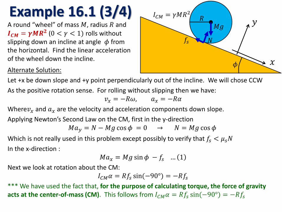
Example 16.1 (4/4) A round “wheel” of mass 𝑀, radius 𝑅 and 𝑰𝑪𝑪 = 𝜸𝑪𝑹𝟐 (0 < 𝛾 < 1) rolls without slipping down an incline at angle 𝜙 from the horizontal. Find the linear acceleration of the wheel down the incline.
Solution (continued): From last page 𝑀𝑎𝑥 = 𝑀𝑀 sin𝜙 − 𝑓𝑠 … 1 𝐼𝐶𝐶𝑅 = 𝑅𝑓𝑠 sin(−90°) = −𝑅𝑓𝑠
But 𝑎𝑥 = −𝑅𝑅,→ 𝑅 = −𝑎𝑥 𝑅⁄ , and so we have
𝛾𝑀𝑅2 ∙−𝑎𝑥𝑅 = 𝑅𝑓𝑠, → −𝛾𝑀𝑎𝑥 = 𝑓𝑠 … (2)
substituting (2) back into (1) for 𝑓𝑠: 𝑀𝑎𝑥 = 𝑀𝑀 sin𝜙 − 𝛾𝑀𝑎𝑥, → 1 + 𝛾 𝑀𝑎𝑥 = 𝑀𝑀 sin𝜙
And so we have:
𝑎𝑥 =𝑀 sin𝜙 1 + 𝛾
Example given in Main Point: Solid Ball/Sphere
𝐼 =25𝑀𝑅2 → 𝛾 =
25
→ 1 + 𝛾 =75
→ 1
1 + 𝛾=
75
𝑎𝑥 =75𝑀 sin𝜙
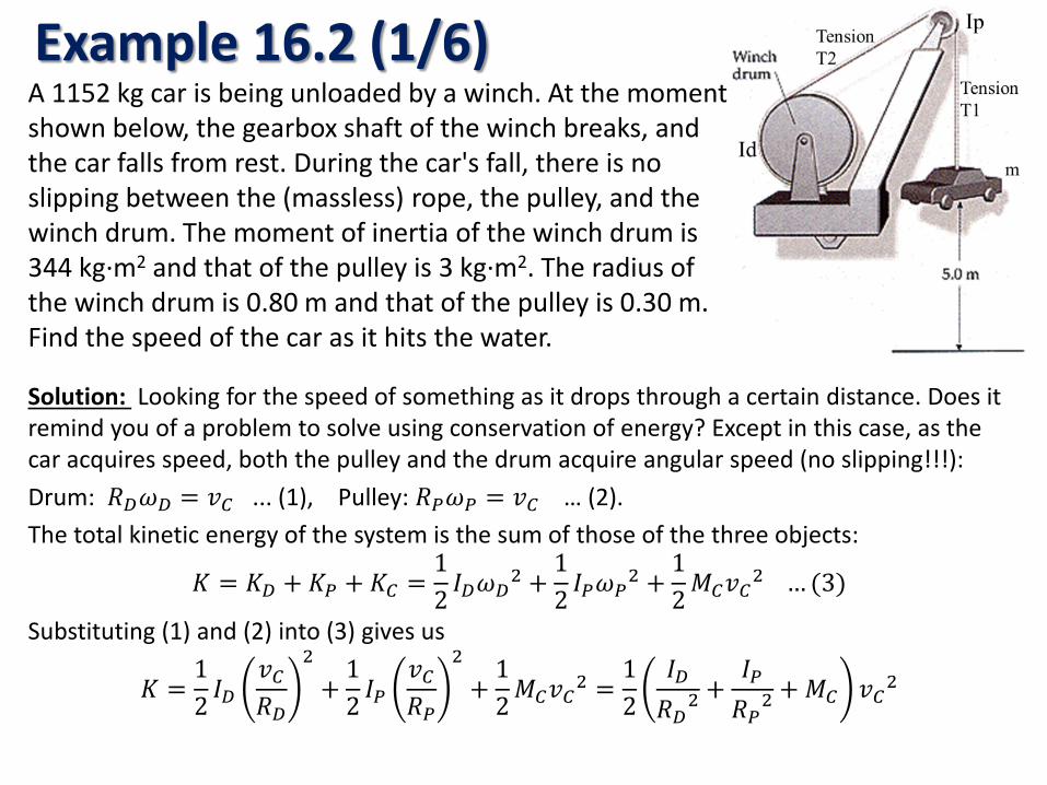
Example 16.2 (1/6) A 1152 kg car is being unloaded by a winch. At the moment shown below, the gearbox shaft of the winch breaks, and the car falls from rest. During the car's fall, there is no slipping between the (massless) rope, the pulley, and the winch drum. The moment of inertia of the winch drum is 344 kg·m2 and that of the pulley is 3 kg·m2. The radius of the winch drum is 0.80 m and that of the pulley is 0.30 m. Find the speed of the car as it hits the water.
Solution: Looking for the speed of something as it drops through a certain distance. Does it remind you of a problem to solve using conservation of energy? Except in this case, as the car acquires speed, both the pulley and the drum acquire angular speed (no slipping!!!): Drum: 𝑅𝐷𝜔𝐷 = 𝑣𝐶 ... (1), Pulley: 𝑅𝑃𝜔𝑃 = 𝑣𝐶 … (2). The total kinetic energy of the system is the sum of those of the three objects:
𝐾 = 𝐾𝐷 + 𝐾𝑃 + 𝐾𝐶 =12 𝐼𝐷𝜔𝐷
2 +12 𝐼𝑃𝜔𝑃
2 +12𝑀𝐶𝑣𝐶2 … (3)
Substituting (1) and (2) into (3) gives us
𝐾 =12 𝐼𝐷
𝑣𝐶𝑅𝐷
2
+12 𝐼𝑃
𝑣𝐶𝑅𝑃
2
+12𝑀𝐶𝑣𝐶2 =
12
𝐼𝐷𝑅𝐷2
+𝐼𝑃𝑅𝑃2
+ 𝑀𝐶 𝑣𝐶2
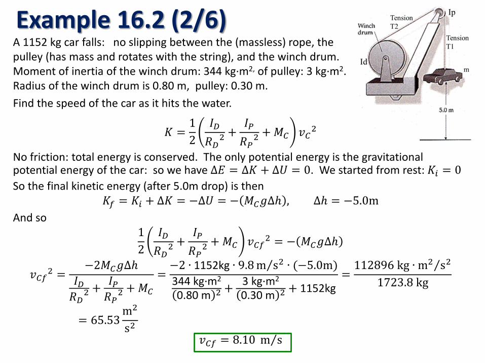
Example 16.2 (2/6) A 1152 kg car falls: no slipping between the (massless) rope, the pulley (has mass and rotates with the string), and the winch drum. Moment of inertia of the winch drum: 344 kg·m2, of pulley: 3 kg·m2. Radius of the winch drum is 0.80 m, pulley: 0.30 m. Find the speed of the car as it hits the water.
𝐾 =12
𝐼𝐷𝑅𝐷2
+𝐼𝑃𝑅𝑃2
+ 𝑀𝐶 𝑣𝐶2
No friction: total energy is conserved. The only potential energy is the gravitational potential energy of the car: so we have ∆𝐸 = ∆𝐾 + ∆𝑈 = 0. We started from rest: 𝐾𝑖 = 0 So the final kinetic energy (after 5.0m drop) is then
𝐾𝑓 = 𝐾𝑖 + ∆𝐾 = −∆𝑈 = − 𝑀𝐶𝑀∆ℎ , ∆ℎ = −5.0m And so
12
𝐼𝐷𝑅𝐷2
+𝐼𝑃𝑅𝑃2
+ 𝑀𝐶 𝑣𝐶𝑓2 = − 𝑀𝐶𝑀∆ℎ
𝑣𝐶𝑓2 =−2𝑀𝐶𝑀∆ℎ
𝐼𝐷𝑅𝐷2
+ 𝐼𝑃𝑅𝑃2
+ 𝑀𝐶
=−2 ∙ 1152kg ∙ 9.8 m s2⁄ ∙ (−5.0m)344 kg·m2
0.80 m 2 + 3 kg·m2
0.30 m 2 + 1152kg=
112896 kg ∙ m2 s2⁄1723.8 kg
= 65.53m2
s2
𝑣𝐶𝑓 = 8.10 m s⁄
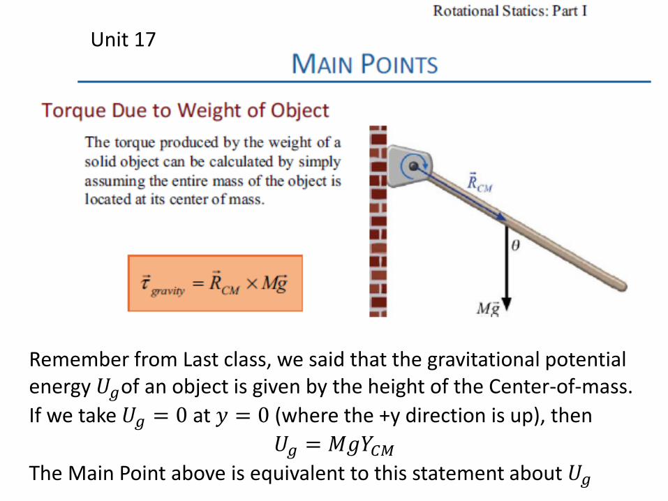
Unit 17
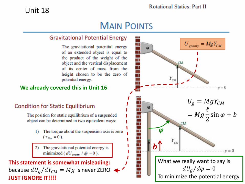
Remember from Last class, we said that the gravitational potential energy 𝑈𝑔of an object is given by the height of the Center-of-mass. If we take 𝑈𝑔 = 0 at 𝑦 = 0 (where the +y direction is up), then
𝑈𝑔 = 𝑀𝑀𝑌𝐶𝐶 The Main Point above is equivalent to this statement about 𝑈𝑔
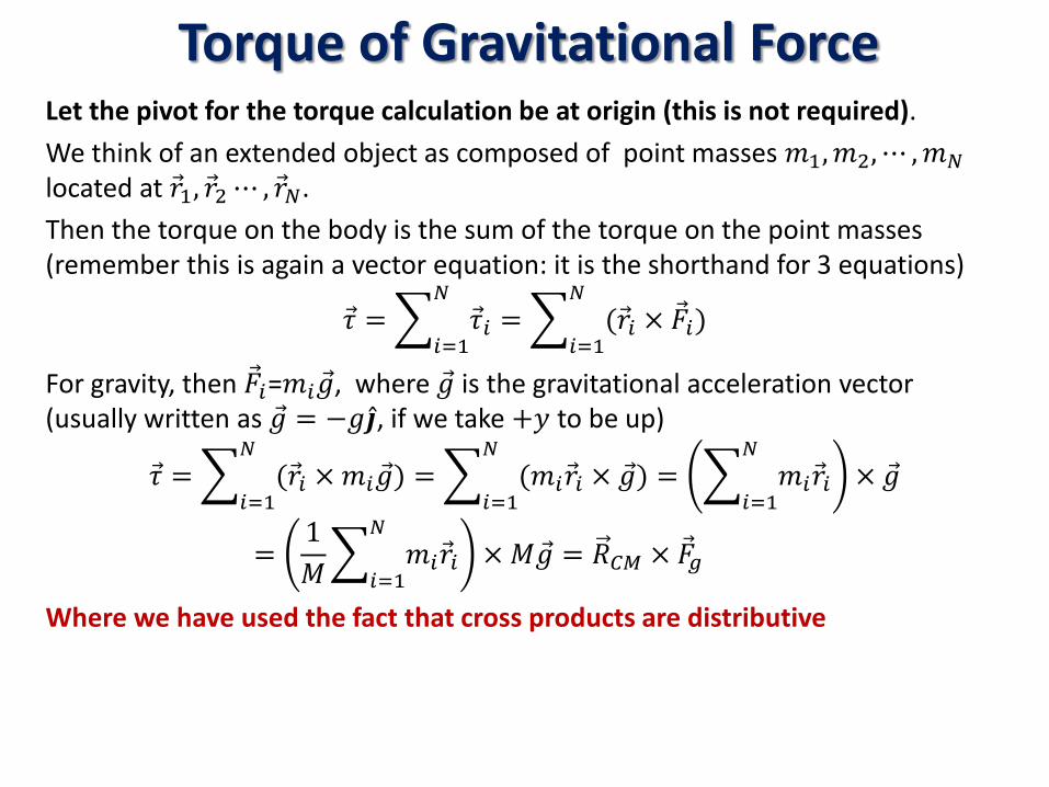
Torque of Gravitational Force Let the pivot for the torque calculation be at origin (this is not required). We think of an extended object as composed of point masses 𝑚1,𝑚2,⋯ ,𝑚𝑁 located at 𝑟1, 𝑟2 ⋯ , 𝑟𝑁. Then the torque on the body is the sum of the torque on the point masses (remember this is again a vector equation: it is the shorthand for 3 equations)
𝜏 = � 𝜏𝑖𝑁
𝑖=1= � (𝑟𝑖 × �⃗�𝑖)
𝑁
𝑖=1
For gravity, then �⃗�𝑖=𝑚𝑖�⃗�, where �⃗� is the gravitational acceleration vector (usually written as �⃗� = −𝑀�̂�, if we take +𝑦 to be up)
𝜏 = � (𝑟𝑖 × 𝑚𝑖�⃗�𝑁
𝑖=1) = � (𝑚𝑖𝑟𝑖 × �⃗�
𝑁
𝑖=1) = � 𝑚𝑖𝑟𝑖
𝑁
𝑖=1× �⃗�
=1𝑀� 𝑚𝑖𝑟𝑖
𝑁
𝑖=1× 𝑀�⃗� = 𝑅𝐶𝐶 × �⃗�𝑔
Where we have used the fact that cross products are distributive
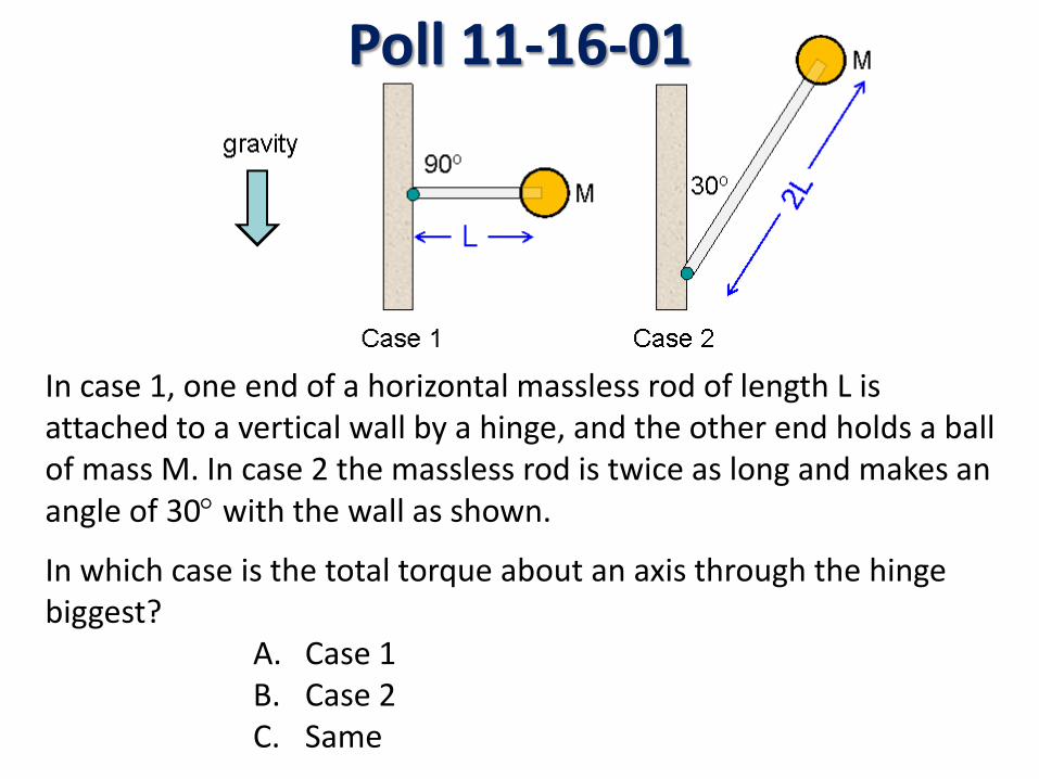
Poll 11-16-01
In case 1, one end of a horizontal massless rod of length L is attached to a vertical wall by a hinge, and the other end holds a ball of mass M. In case 2 the massless rod is twice as long and makes an angle of 30° with the wall as shown.
In which case is the total torque about an axis through the hinge biggest?
A. Case 1 B. Case 2 C. Same
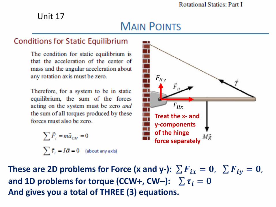
Unit 17
These are 2D problems for Force (x and y-): ∑𝑭𝒊𝒊 = 𝟎, ∑𝑭𝒊𝒚 = 𝟎, and 1D problems for torque (CCW+, CW−): ∑𝝉𝒊 = 𝟎 And gives you a total of THREE (3) equations.
Treat the x- and y-components of the hinge force separately
𝐹𝐻𝑥
𝐹𝐻𝑦
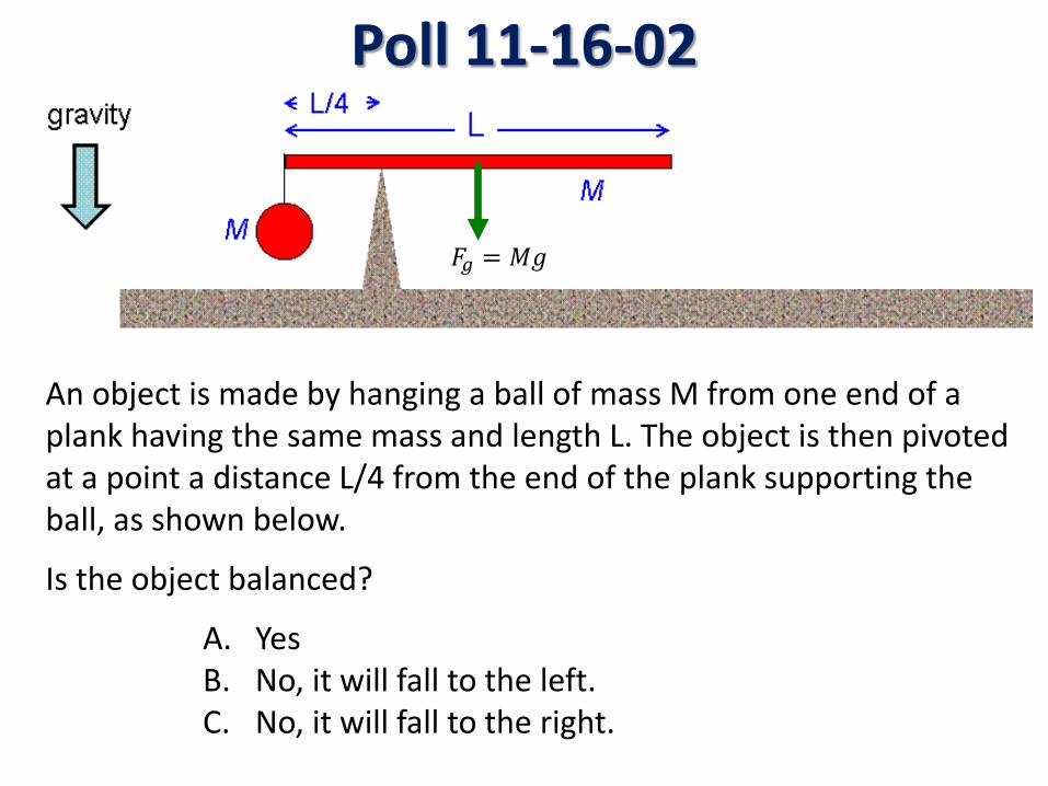
Poll 11-16-02
An object is made by hanging a ball of mass M from one end of a plank having the same mass and length L. The object is then pivoted at a point a distance L/4 from the end of the plank supporting the ball, as shown below.
Is the object balanced?
A. Yes B. No, it will fall to the left. C. No, it will fall to the right.
𝐹𝑔 = 𝑀𝑀
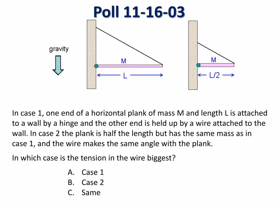
Poll 11-16-03
In case 1, one end of a horizontal plank of mass M and length L is attached to a wall by a hinge and the other end is held up by a wire attached to the wall. In case 2 the plank is half the length but has the same mass as in case 1, and the wire makes the same angle with the plank.
In which case is the tension in the wire biggest?
A. Case 1 B. Case 2 C. Same
Unit 17
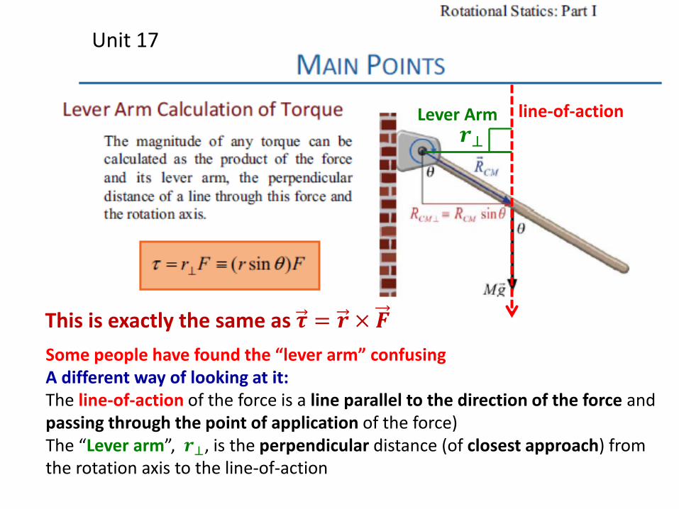
This is exactly the same as 𝝉 = 𝒓 × 𝑭 Some people have found the “lever arm” confusing A different way of looking at it: The line-of-action of the force is a line parallel to the direction of the force and passing through the point of application of the force) The “Lever arm”, 𝒓⊥, is the perpendicular distance (of closest approach) from the rotation axis to the line-of-action
line-of-action 𝒓⊥
Lever Arm
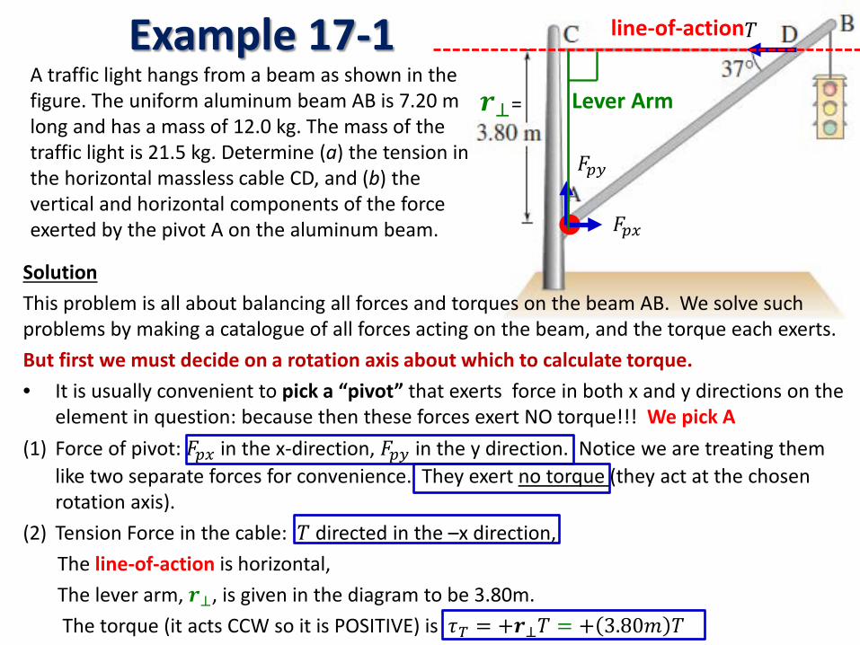
Example 17-1 A traffic light hangs from a beam as shown in the figure. The uniform aluminum beam AB is 7.20 m long and has a mass of 12.0 kg. The mass of the traffic light is 21.5 kg. Determine (a) the tension in the horizontal massless cable CD, and (b) the vertical and horizontal components of the force exerted by the pivot A on the aluminum beam.
Solution This problem is all about balancing all forces and torques on the beam AB. We solve such problems by making a catalogue of all forces acting on the beam, and the torque each exerts. But first we must decide on a rotation axis about which to calculate torque. • It is usually convenient to pick a “pivot” that exerts force in both x and y directions on the
element in question: because then these forces exert NO torque!!! We pick A (1) Force of pivot: 𝐹𝑝𝑥 in the x-direction, 𝐹𝑝𝑦 in the y direction. Notice we are treating them
like two separate forces for convenience. They exert no torque (they act at the chosen rotation axis).
(2) Tension Force in the cable: 𝑇 directed in the –x direction, The line-of-action is horizontal, The lever arm, 𝒓⊥, is given in the diagram to be 3.80m. The torque (it acts CCW so it is POSITIVE) is 𝜏𝑇 = +𝒓⊥𝑇 = + 3.80𝑚 𝑇
𝑇 line-of-action
𝐹𝑝𝑥
𝐹𝑝𝑦
𝒓⊥= Lever Arm
Example 17-1
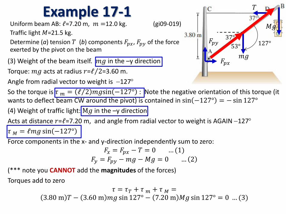
(3) Weight of the beam itself. 𝑚𝑀 in the –y direction Torque: 𝑚𝑀 acts at radius 𝑟=ℓ 2⁄ =3.60 m. Angle from radial vector to weight is −127° So the torque is 𝜏 𝑚 = ℓ 2⁄ 𝑚𝑀sin −127° : Note the negative orientation of this torque (it wants to deflect beam CW around the pivot) is contained in sin −127° = − sin 127° (4) Weight of traffic light: M𝑀 in the –y direction Acts at distance 𝑟=ℓ=7.20 m, and angle from radial vector to weight is AGAIN −127° 𝜏 𝐶 = ℓ𝑚𝑀 sin −127° Force components in the x- and y-direction independently sum to zero:
𝐹𝑥 = 𝐹𝑝𝑥 − 𝑇 = 0 … (1) 𝐹𝑦 = 𝐹𝑝𝑦 − 𝑚𝑀 −𝑀𝑀 = 0 … 2
(*** note you CANNOT add the magnitudes of the forces) Torques add to zero
𝜏 = 𝜏𝑇 + 𝜏 𝑚 + 𝜏 𝐶 = 3.80 m 𝑇 − 3.60 m 𝑚𝑀 sin 127° − 7.20 m 𝑀𝑀 sin 127° = 0 … (3)
𝐹𝑝𝑥
𝐹𝑝𝑦
𝑇
𝑚𝑀
37° 53° 127°
𝑀𝑀 Uniform beam AB: ℓ=7.20 m, 𝑚 =12.0 kg. (gi09-019) Traffic light 𝑀=21.5 kg. Determine (a) tension 𝑇 (b) components 𝐹𝑝𝑥, 𝐹𝑝𝑦 of the force exerted by the pivot on the beam
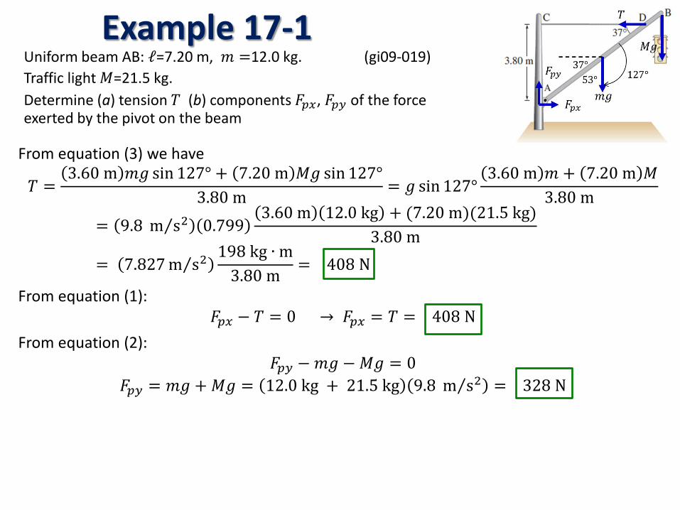
Example 17-1 Uniform beam AB: ℓ=7.20 m, 𝑚 =12.0 kg. (gi09-019) Traffic light 𝑀=21.5 kg. Determine (a) tension 𝑇 (b) components 𝐹𝑝𝑥, 𝐹𝑝𝑦 of the force exerted by the pivot on the beam
From equation (3) we have
𝑇 =3.60 m 𝑚𝑀 sin 127° + 7.20 m 𝑀𝑀 sin 127°
3.80 m = 𝑀 sin 127°3.60 m 𝑚 + 7.20 m 𝑀
3.80 m= 9.8 m s2⁄ 0.799
3.60 m 12.0 kg + (7.20 m)(21.5 kg)3.80 m
= 7.827 m s2⁄198 kg ∙ m
3.80 m = 408 N
From equation (1): 𝐹𝑝𝑥 − 𝑇 = 0 → 𝐹𝑝𝑥 = 𝑇 = 408 N
From equation (2): 𝐹𝑝𝑦 − 𝑚𝑀 −𝑀𝑀 = 0
𝐹𝑝𝑦 = 𝑚𝑀 + 𝑀𝑀 = 12.0 kg + 21.5 kg 9.8 m s2⁄ = 328 N
Unit 18
We already covered this in Unit 16
This statement is somewhat misleading: because 𝑑𝑈𝑔 𝑑𝑌𝐶𝐶⁄ = 𝑀𝑀 is never ZERO JUST IGNORE IT!!!!
𝝋
What we really want to say is 𝑑𝑈𝑔 𝑑𝜑⁄ = 0
To minimize the potential energy
𝑈𝑔 = 𝑀𝑀𝑌𝐶𝐶
= 𝑀𝑀ℓ2
sin𝜑 + 𝑏
𝒃
Unit 18
𝐹𝑝𝑥
𝐹𝑝𝑦
𝑇
𝑚𝑀
37° 53° 127°
𝑀𝑀
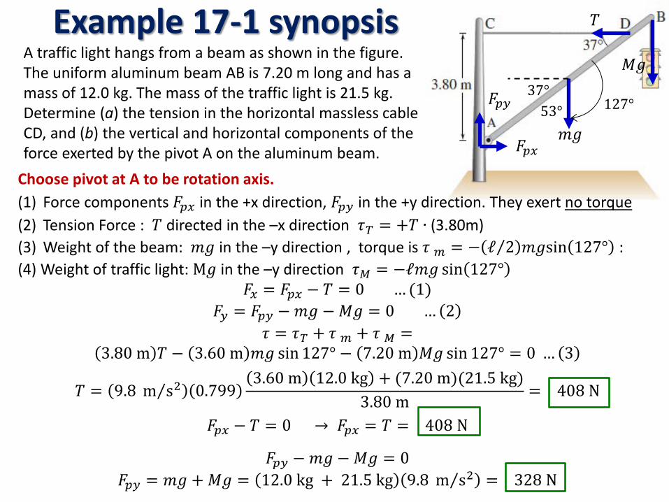
Example 17-1 synopsis A traffic light hangs from a beam as shown in the figure. The uniform aluminum beam AB is 7.20 m long and has a mass of 12.0 kg. The mass of the traffic light is 21.5 kg. Determine (a) the tension in the horizontal massless cable CD, and (b) the vertical and horizontal components of the force exerted by the pivot A on the aluminum beam.
Choose pivot at A to be rotation axis. (1) Force components 𝐹𝑝𝑥 in the +x direction, 𝐹𝑝𝑦 in the +y direction. They exert no torque (2) Tension Force : 𝑇 directed in the –x direction 𝜏𝑇 = +𝑇 ∙ (3.80m) (3) Weight of the beam: 𝑚𝑀 in the –y direction , torque is 𝜏 𝑚 = − ℓ 2⁄ 𝑚𝑀sin 127° : (4) Weight of traffic light: M𝑀 in the –y direction 𝜏𝐶 = −ℓ𝑚𝑀 sin 127°
𝐹𝑥 = 𝐹𝑝𝑥 − 𝑇 = 0 … (1) 𝐹𝑦 = 𝐹𝑝𝑦 − 𝑚𝑀 −𝑀𝑀 = 0 … 2
𝜏 = 𝜏𝑇 + 𝜏 𝑚 + 𝜏 𝐶 = 3.80 m 𝑇 − 3.60 m 𝑚𝑀 sin 127° − 7.20 m 𝑀𝑀 sin 127° = 0 … 3
𝑇 = 9.8 m s2⁄ 0.7993.60 m 12.0 kg + (7.20 m)(21.5 kg)
3.80 m = 408 N
𝐹𝑝𝑥 − 𝑇 = 0 → 𝐹𝑝𝑥 = 𝑇 = 408 N
𝐹𝑝𝑦 − 𝑚𝑀 −𝑀𝑀 = 0 𝐹𝑝𝑦 = 𝑚𝑀 + 𝑀𝑀 = 12.0 kg + 21.5 kg 9.8 m s2⁄ = 328 N
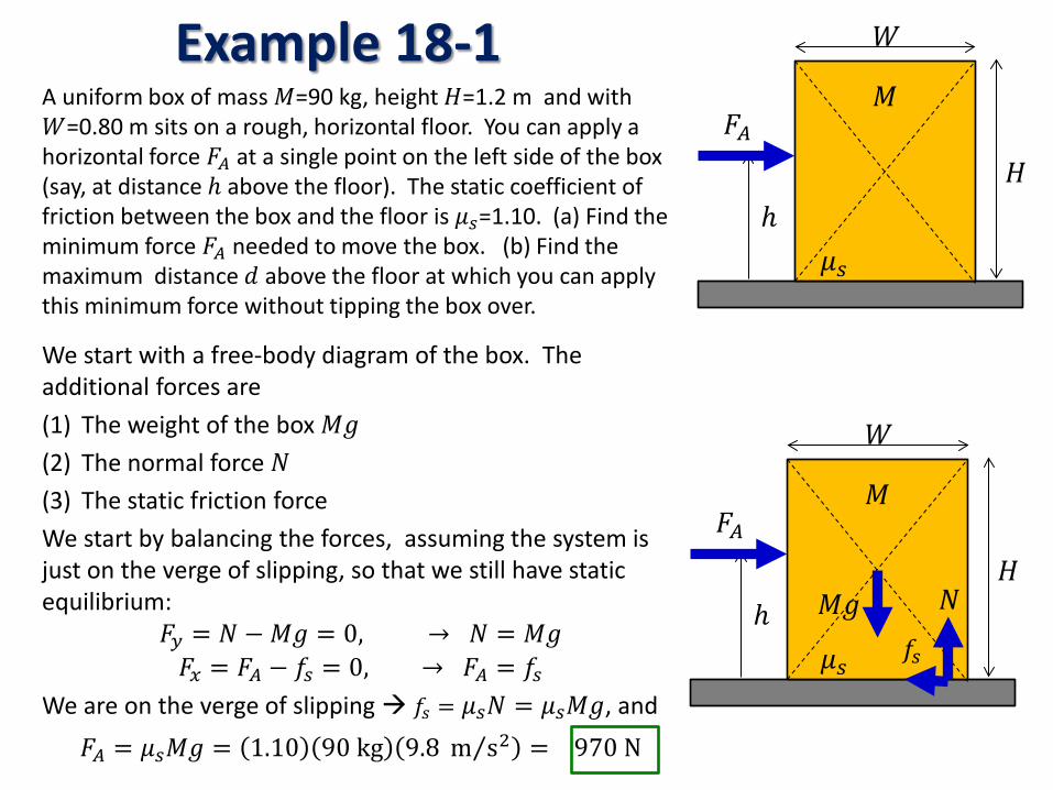
Example 18-1 A uniform box of mass 𝑀=90 kg, height 𝐻=1.2 m and with 𝑊=0.80 m sits on a rough, horizontal floor. You can apply a horizontal force 𝐹𝐴 at a single point on the left side of the box (say, at distance ℎ above the floor). The static coefficient of friction between the box and the floor is 𝜇𝑠=1.10. (a) Find the minimum force 𝐹𝐴 needed to move the box. (b) Find the maximum distance 𝑑 above the floor at which you can apply this minimum force without tipping the box over.
We start with a free-body diagram of the box. The additional forces are (1) The weight of the box 𝑀𝑀 (2) The normal force 𝑁 (3) The static friction force We start by balancing the forces, assuming the system is just on the verge of slipping, so that we still have static equilibrium:
𝐹𝑦 = 𝑁 −𝑀𝑀 = 0, → 𝑁 = 𝑀𝑀 𝐹𝑥 = 𝐹𝐴 − 𝑓𝑠 = 0, → 𝐹𝐴 = 𝑓𝑠
We are on the verge of slipping 𝑓𝑠 = 𝜇𝑠𝑁 = 𝜇𝑠𝑀𝑀, and
𝐹𝐴 = 𝜇𝑠𝑀𝑀 = 1.10 90 kg 9.8 m s2⁄ = 970 N
𝐻
𝑊
ℎ
𝐹𝐴 𝑀
𝜇𝑠
𝐻
𝑊
ℎ
𝐹𝐴 𝑀
𝜇𝑠
𝑀𝑀 𝑁
𝑓𝑠
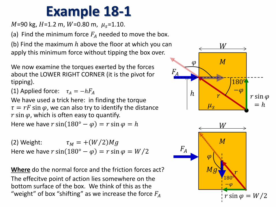
Example 18-1 𝑀=90 kg, 𝐻=1.2 m, 𝑊=0.80 m, 𝜇𝑠=1.10. (a) Find the minimum force 𝐹𝐴 needed to move the box. (b) Find the maximum ℎ above the floor at which you can apply this minimum force without tipping the box over.
We now examine the torques exerted by the forces about the LOWER RIGHT CORNER (it is the pivot for tipping). (1) Applied force: 𝜏𝐴 = −ℎ𝐹𝐴 We have used a trick here: in finding the torque 𝜏 = 𝑟𝐹 sin𝜑, we can also try to identify the distance 𝑟 sin𝜑, which is often easy to quantify. Here we have 𝑟 sin 180° − 𝜑 = 𝑟 sin𝜑 = ℎ (2) Weight: 𝜏𝐶 = + 𝑊 2⁄ 𝑀𝑀 Here we have 𝑟 sin 180° − 𝜑 = 𝑟 sin𝜑 = 𝑊 2⁄ Where do the normal force and the friction forces act? The effecitve point of action lies somewhere on the bottom surface of the box. We think of this as the “weight” of box “shifting” as we increase the force 𝐹𝐴
𝑊
ℎ
𝐹𝐴 𝑀
𝜇𝑠 𝑟 𝑟 sin𝜑
= ℎ
𝜑
180° −𝜑
𝑊
𝐹𝐴 𝑀
𝑀𝑀 𝑟
𝑟 sin𝜑 = 𝑊 2⁄
𝜑
180° −𝜑
Example 18-1
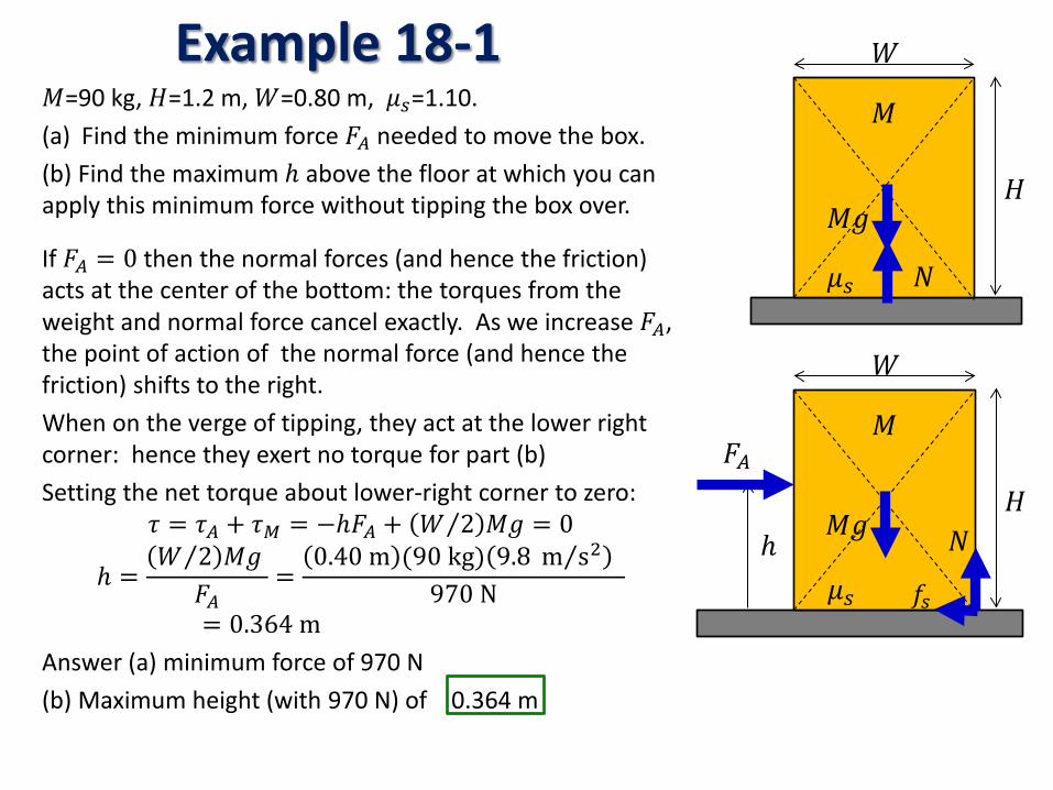
If 𝐹𝐴 = 0 then the normal forces (and hence the friction) acts at the center of the bottom: the torques from the weight and normal force cancel exactly. As we increase 𝐹𝐴, the point of action of the normal force (and hence the friction) shifts to the right. When on the verge of tipping, they act at the lower right corner: hence they exert no torque for part (b) Setting the net torque about lower-right corner to zero:
𝜏 = 𝜏𝐴 + 𝜏𝐶 = −ℎ𝐹𝐴 + 𝑊 2⁄ 𝑀𝑀 = 0
ℎ =𝑊 2⁄ 𝑀𝑀
𝐹𝐴=
0.40 m (90 kg) 9.8 m s2⁄ 970 N
= 0.364 m Answer (a) minimum force of 970 N (b) Maximum height (with 970 N) of 0.364 m
𝐻
𝑊
𝑀
𝜇𝑠
𝑀𝑀
𝑁
𝑀=90 kg, 𝐻=1.2 m, 𝑊=0.80 m, 𝜇𝑠=1.10. (a) Find the minimum force 𝐹𝐴 needed to move the box. (b) Find the maximum ℎ above the floor at which you can apply this minimum force without tipping the box over.
𝐻
𝑊
ℎ
𝐹𝐴 𝑀
𝜇𝑠
𝑁
𝑓𝑠
𝑀𝑀