Embed Size (px)
Citation preview
Physics 1502: Lecture 22Today’s Agenda
• Announcements:– RL - RV - RLC circuits
• Homework 06: due next Wednesday …Homework 06: due next Wednesday …
• Induction / AC current
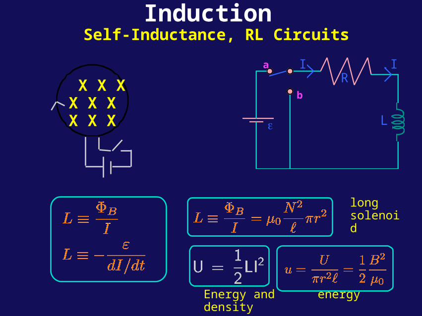
InductionSelf-Inductance, RL Circuits
X X X X X X X X X
RI
ε
a
b
L
I
long solenoid
Energy and energy density
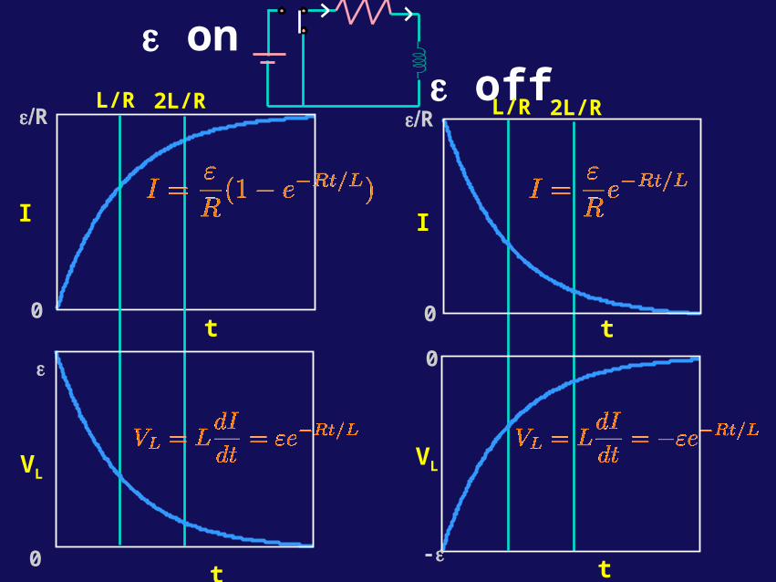
t
I
0
εRL/R 2L/R
VL
0t
ε
ε on ε off
0
-ε
VL
t
L/R 2L/R
t
I
0
εR
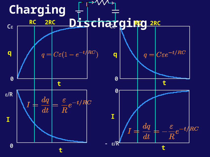
t
q
0
CεRC 2RC
I
0t
εR
Charging Discharging
0
- εR
I
t
RC 2RC
t
q
0
Cε
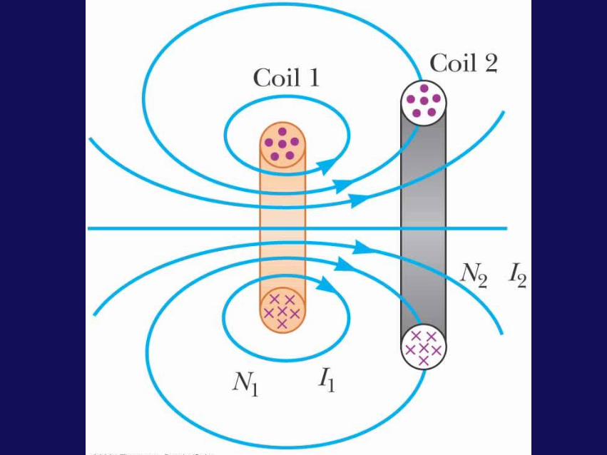
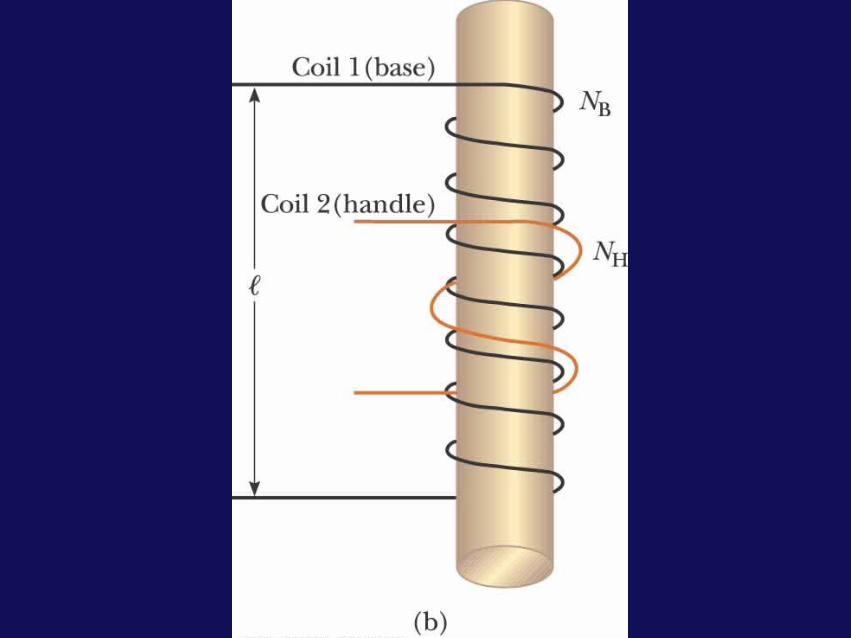
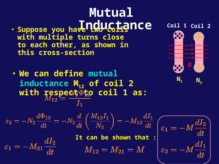
Mutual Inductance• Suppose you have two coils
with multiple turns close to each other, as shown in this cross-section
• We can define mutual inductance M12 of coil 2 with respect to coil 1 as:
Coil 1 Coil 2
B
N1 N2
It can be shown that :
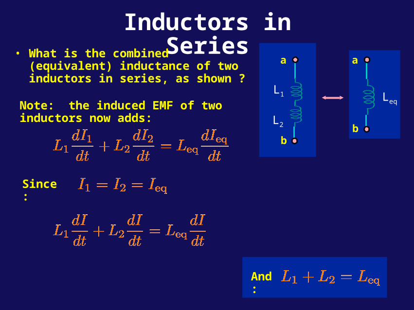
Inductors in Series• What is the combined (equivalent)
inductance of two inductors in series, as shown ?
a
b
L2
L1
a
b
LeqNote: the induced EMF of two inductors now adds:
Since:
And:
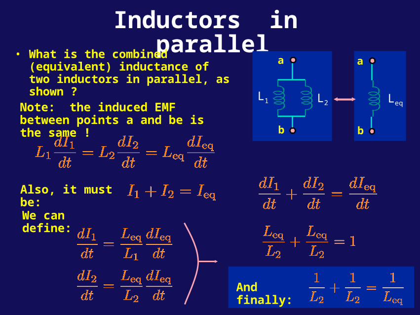
Inductors in parallel• What is the combined (equivalent)
inductance of two inductors in parallel, as shown ?
a
b
L2L1
a
b
LeqNote: the induced EMF between points a and be is the same !
Also, it must be:
We can define:
And finally:
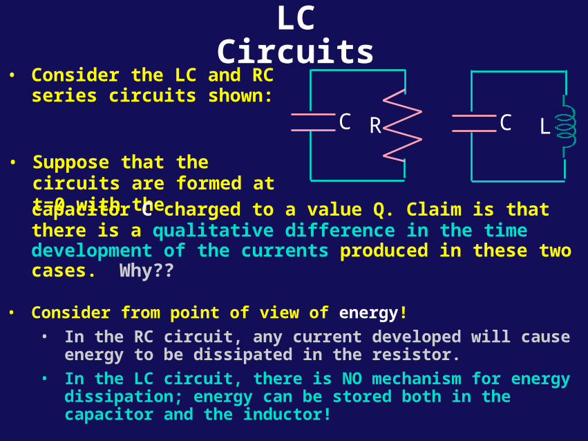
LC Circuits
• Consider the LC and RC series circuits shown:
LCC R
• Suppose that the circuits are formed at t=0 with the
capacitor C charged to a value Q. Claim is that there is a qualitative difference in the time development of the currents produced in these two cases. Why??
• Consider from point of view of energy!
• In the RC circuit, any current developed will cause energy to be dissipated in the resistor.
• In the LC circuit, there is NO mechanism for energy dissipation; energy can be stored both in the capacitor and the inductor!
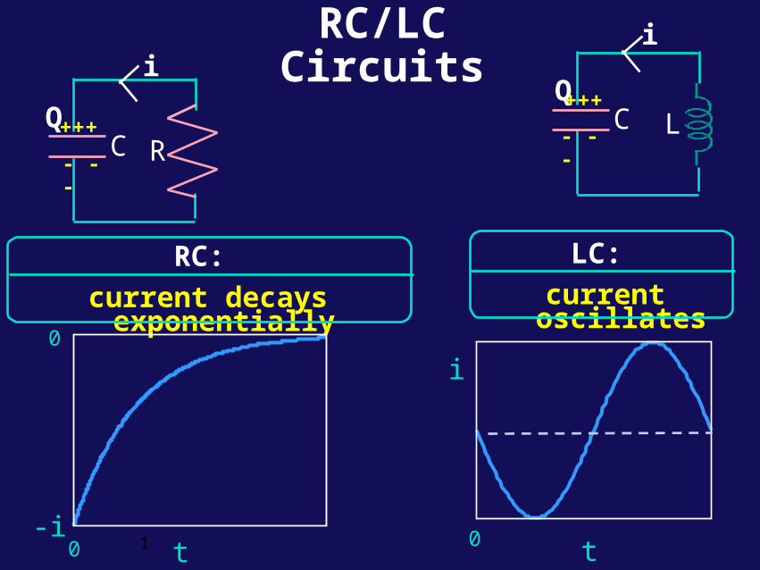
RC/LC Circuits
RC:
current decays exponentially
C R
i
Q
-it
0
0 1
+++
- - -
LC
LC:
current oscillates
i
0 t
i
Q+++
- - -
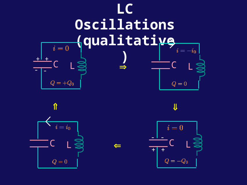
LC Oscillations(qualitative)
LC+ +
- -
LC
LC+ +
- -LC
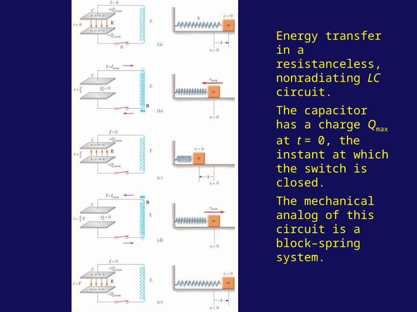
Energy transfer in a resistanceless, nonradiating LC circuit.
The capacitor has a charge Qmax at t = 0, the instant at which the switch is closed.
The mechanical analog of this circuit is a block–spring system.
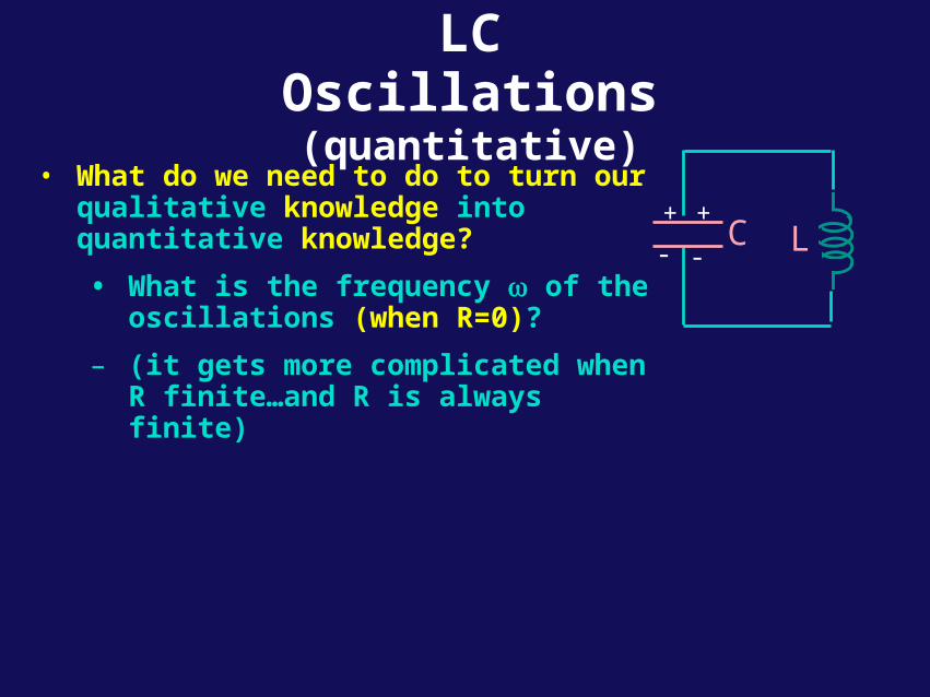
LC Oscillations(quantitative)
• What do we need to do to turn our qualitative knowledge into quantitative knowledge?
• What is the frequency of the oscillations (when R=0)?
– (it gets more complicated when R finite…and R is always finite)
LC+ +
- -
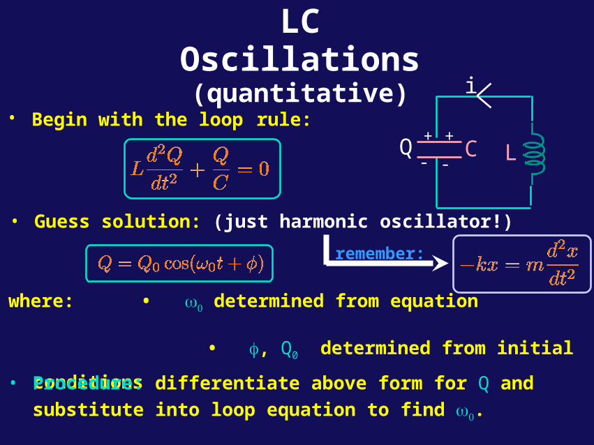
LC Oscillations(quantitative)
• Begin with the loop rule:
• Guess solution: (just harmonic oscillator!)
where: • determined from equation
• , Q0 determined from initial conditions • Procedure: differentiate above form for Q and substitute into
loop equation to find .
LC+ +
- -
i
Q
remember:
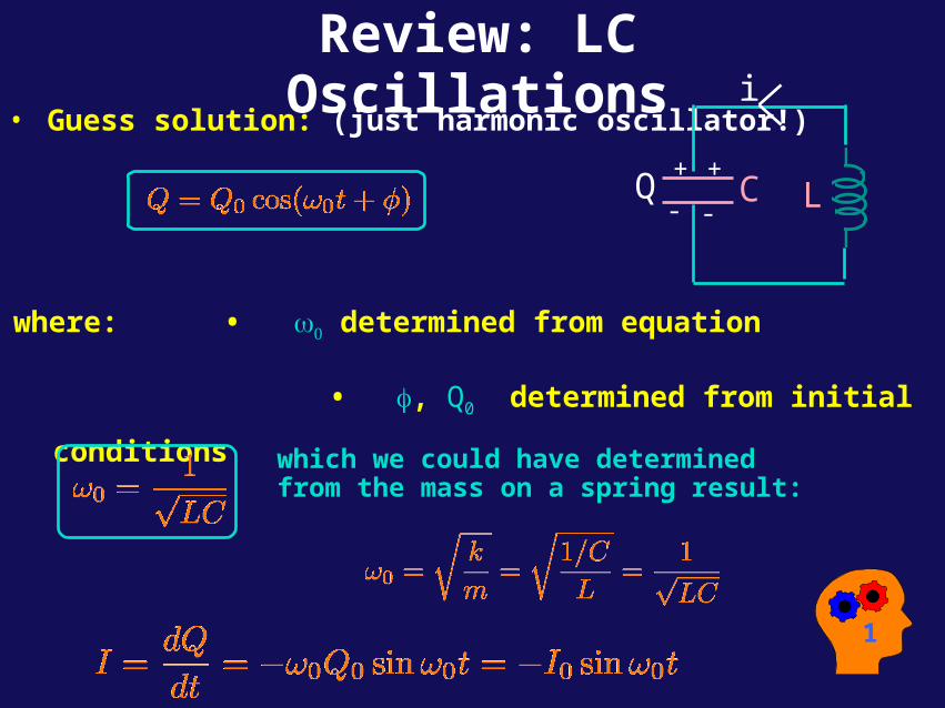
Review: LC Oscillations
• Guess solution: (just harmonic oscillator!)
where: • determined from equation
• , Q0 determined from initial conditions
LC+ +
- -
i
Q
1
which we could have determinedfrom the mass on a spring result:
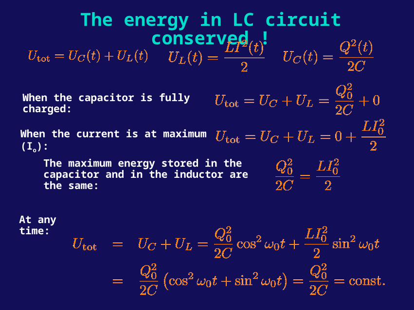
The energy in LC circuit conserved !
When the capacitor is fully charged:
When the current is at maximum (Io):
At any time:
The maximum energy stored in the capacitor and in the inductor are the same:
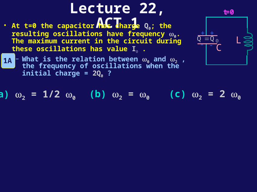
Lecture 22, ACT 1• At t=0 the capacitor has charge Q0; the resulting
oscillations have frequency 0. The maximum current in the circuit during these oscillations has value I . – What is the relation between 0 and 2 , the
frequency of oscillations when the initial charge = 2Q0 ?
(a) 2 = 1/2 0 (b) 2 = 0 (c) 2 = 2 0
1A
LC
+ +
- -Q Q=
t=0
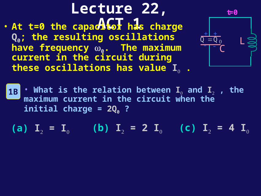
Lecture 22, ACT 1• At t=0 the capacitor has charge Q0; the
resulting oscillations have frequency 0. The maximum current in the circuit during these oscillations has value I .
(a) I = I (b) I = 2 I (c) I = 4 I
• What is the relation between I and I , the maximum current in the circuit when the initial charge = 2Q0 ?
1B
LC
+ +
- -Q Q=
t=0
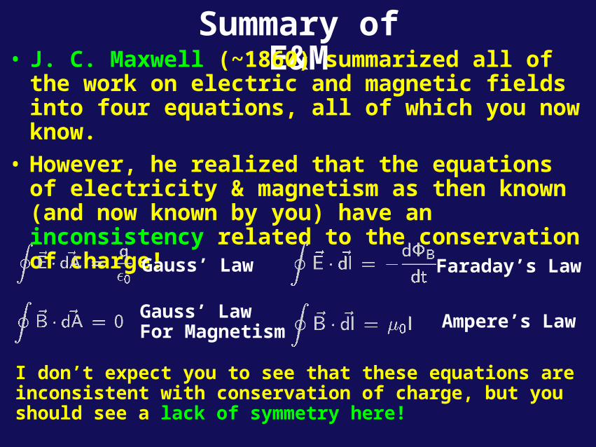
Summary of E&M• J. C. Maxwell (~1860) summarized all of the work on
electric and magnetic fields into four equations, all of which you now know.
• However, he realized that the equations of electricity & magnetism as then known (and now known by you) have an inconsistency related to the conservation of charge!
I don’t expect you to see that these equations are inconsistent with conservation of charge, but you should see a lack of symmetry here!
Gauss’ Law
Gauss’ LawFor Magnetism
Faraday’s Law
Ampere’s Law
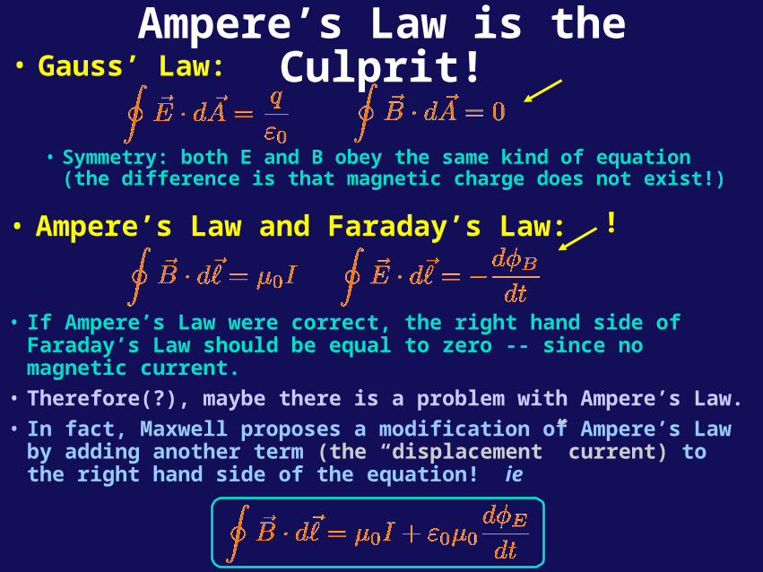
Ampere’s Law is the Culprit!• Gauss’ Law:
• Symmetry: both E and B obey the same kind of equation (the difference is that magnetic charge does not exist!)
• Ampere’s Law and Faraday’s Law:
• If Ampere’s Law were correct, the right hand side of Faraday’s Law should be equal to zero -- since no magnetic current.
• Therefore(?), maybe there is a problem with Ampere’s Law.
• In fact, Maxwell proposes a modification of Ampere’s Law by adding another term (the “displacement” current) to the right hand side of the equation! ie
!
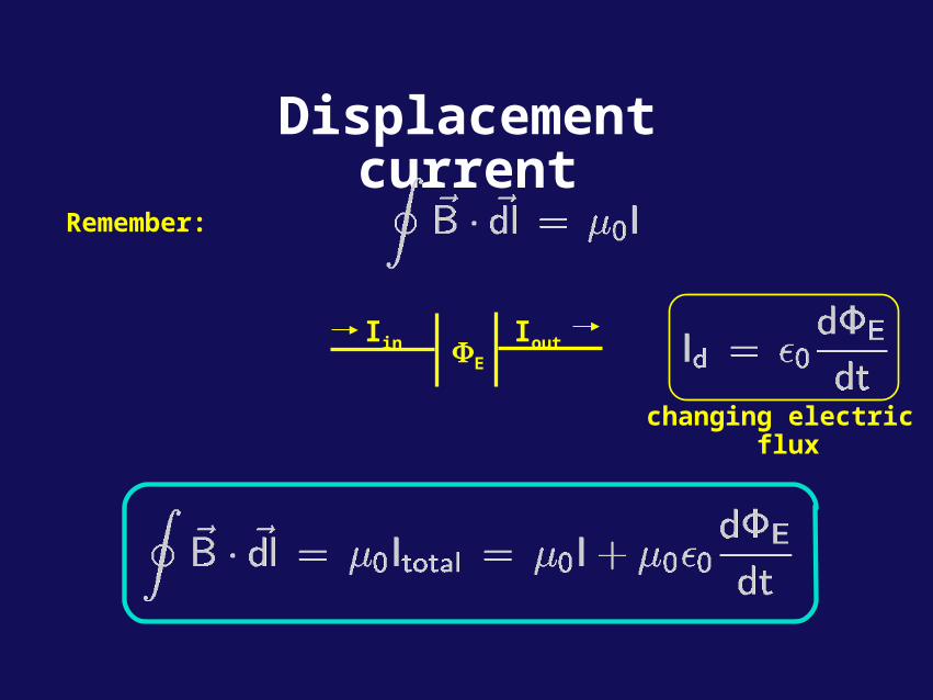
Displacement current
Remember:
E
Iin Iout
changing electric flux
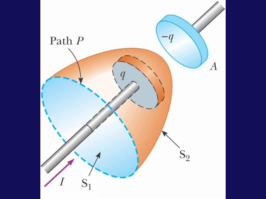
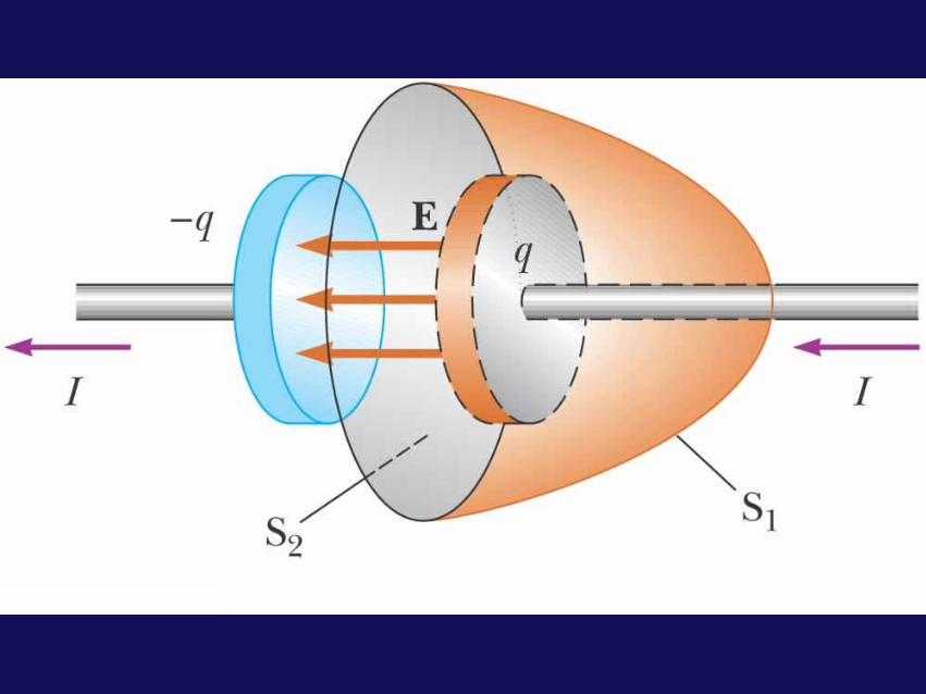
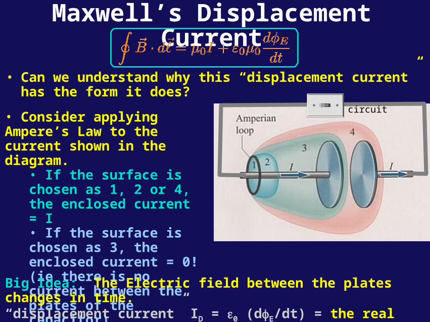
Maxwell’s Displacement Current
• Can we understand why this “displacement current” has the form it does?
• Consider applying Ampere’s Law to the current shown in the diagram.
• If the surface is chosen as 1, 2 or 4, the enclosed current = I• If the surface is chosen as 3, the enclosed current = 0! (ie there is no current between the plates of the capacitor)
Big Idea: The Electric field between the plates changes in time. “displacement current” ID = ε0 (dE/dt) = the real current I in the wire.
circuit
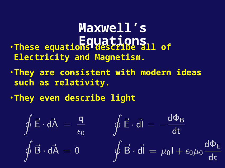
Maxwell’s Equations• These equations describe all of Electricity and
Magnetism.
• They are consistent with modern ideas such as relativity.
• They even describe light