Embed Size (px)
Citation preview

PHYSICAL RESEARCH LABORATORY
Page 1 of 53
Glossary and List of Abbreviations
HA: High Availability. HPC: High Performance Computing Cluster including compute nodes, HA master nodes, storage server(s), storage solution, backup server and tape library. HPC Solution: HPC along with DG-Set, UPS, UPS batteries and A.C. OEM: Original Equipment Manufacturer. On-site: Physical Research Laboratory, Navrangpura, Ahmedabad 380009. PRL: Physical Research Laboratory. Pure CPU Architecture: Collection of compute nodes that are PCIe Accelerator enabled (empty PCIe Accelerator slots) and contains only CPUs. Mixed CPU/PCIe Accelerator Architecture: Collection of compute nodes that contains PCIe Accelerators as well as CPUs. teraFLOPS: Trillions of double precision Floating Point Operations Per Second.

PHYSICAL RESEARCH LABORATORY
Page 2 of 53
Technical Specifications
High Performance Computing Cluster of total sustained 100 teraFLOPS with 50 teraFLOPS of pure CPU and rest 50 teraFLOPS of PCIe Accelerator
Cluster will comprise of the following components/requirements integrated together as a fully operational High Performance Computing Cluster (HPC):
1) Compute Nodes with Pure CPU Architecture (Minimum 77 nodes over Infiniband)
Specifications per compute node
CPU: 2 x Latest 64 Bit Processor from x86, 12 core and 30MB cache or better, with each core capable of executing 8 flops per clock cycle, 2.7GHz or better PCIe Accelerator Support: At least two empty PCI Express bus (Gen 3.0) x16 slots for future FLFH Double wide PCIe Accelerator upgradability
RAM: 256 GB per node ECC DDR3‐1866 MHz or better, and equal distribution of memory on DIMMs and upgradable up to 512 GB.
HDD: 2 × 900 GB SAS 10000 RPM or better, configured for RAID 1.
Infiniband: FDR Infiniband 56Gbps dual port adaptor, QSFP interface in 100% non – blocking modes between the nodes.
NIC: Dual Gigabit (10/100/1000Mbps) Ethernet onboard with PXE boot capability.
RAID: On board hardware controller offering RAID levels 0, 1.
Power Supply: Rack redundant energy efficient (85%) power supply.
Node Serviceability: Each of the nodes must be independently serviceable without affecting functioning of remaining components of cluster.
Management Ports: At least one dedicated port for remote management. Form Factor: 2U or better. All the compute nodes must have the same configuration.
PHYSICAL RESEARCH LABORATORY
Page 3 of 53
2) Compute Nodes with Mixed CPU/PCIe Accelerator Architecture (Minimum 20 nodes over Infiniband)
Specifications per compute node
CPU: 2 x Latest 64 Bit Processor from x86, 12 core and 30MB cache or better, with each core capable of executing 8 flops per clock cycle, 2.7GHz or better
PCIe Accelerator: 2 x PCIe Accelerators with minimum 6GB and Passive Cooling. Please refer point no. 4 for technical specifications. RAM: 256 GB per node ECC DDR3‐1866 MHz or better, and equal distribution of memory on DIMMs upgradable up to 512 GB.
HDD: 2 × 900 GB SAS 10000 RPM or better configured for RAID 1.
Infiniband: FDR Infiniband 56Gbps dual port adaptor, QSFP interface in non – blocking modes between the nodes.
NIC: Dual Gigabit (10/100/1000Mbps) Ethernet onboard with PXE boot capability.
RAID: On board hardware controller offering RAID levels 0, 1.
Power Supply: Rack redundant energy efficient (85%) power supply.
Node Serviceability: Each of the nodes must be independently serviceable without affecting functioning of remaining components of cluster.
Management Ports: At least one dedicated port for remote management. Form Factor: 2U or better.
All the compute nodes must have the same configuration.
Additional details applicable to specification 1 and 2: The number of nodes specified in the technical specifications is the minimum estimated value calculated with more than 95% efficiency of the theoretical peak. The bidders may quote additional compute nodes (in both categories – Sr. No. 1 and 2) required to satisfy conditions (refer point 11 – Acceptance Test Procedure) for sustained performance. The bidder must make sure to house the proposed setup within present HPC room (see annexure I).
Total number of compute nodes must be accommodated within a maximum of ten racks (42U). Refer Terms and Conditions for details.
PHYSICAL RESEARCH LABORATORY
Page 4 of 53
3) Master Node with Redundancy High Availability (HA) mode to Administer Pure CPU and Mixed CPU/PCIe Accelerator Nodes
Configuration: Two master nodes in HA mode and redundant to each other, jointly administering compute nodes. Master nodes will share peripherals (KVM switch, 1U Rack mount TFT with keyboard and mouse) mounted on rack within a 1U slide away housing. Both master nodes must have identical configuration as per specifications below:
Specifications per master node
CPU: 2 x Latest 64 Bit Processor from x86, 12 core and 30MB cache or better, with each core capable of executing 8 flops per clock cycle,2.7GHz or better PCIe Accelerator: 2 x PCIe Accelerators with minimum 6GB and Passive Cooling. Please refer point no. 4 for technical specifications. RAM: 256 GB per node ECC DDR3‐1866 MHz or better, and equal distribution of memory on DIMMs upgradable up to 512 GB. HDD: 2 × 900 GB SAS 10000 RPM or better, configured for RAID 1.
Infiniband: FDR Infiniband 56Gbps dual port adaptor, QSFP interface in 100% non – blocking modes between the nodes.
NIC: Dual Gigabit (10/100/1000Mbps) Ethernet onboard with PXE boot capability Ethernet Management port 10/100Mbps.
RAID: On board hardware controller offering RAID levels 0, 1.
Power Supply: Rack redundant energy efficient (85%) power supply. Node Serviceability: Each of the nodes must be independently serviceable without affecting functioning of remaining components of cluster. Management Ports: At least one port for remote management. Form Factor: 2U or better. The items 1, 2 and 3 (pure CPU nodes, hybrid CPU/PCIe Accelerator nodes and HA master nodes) must be of the same configuration, OEM and model.
PHYSICAL RESEARCH LABORATORY
Page 5 of 53
4) PCIe Accelerator specifications
1. Minimum 1.3 TF DP floating point performance or better 2. Minimum Memory Size per Accelerator‐ 6GB or better 3. Memory Bandwidth ‐320GB/s or better 4. Core Interconnect‐Point‐to‐Point 5. Should enable multiple CPU cores to simultaneously use the Accelerator cores of a single PCIe Accelerator 6. PCIe Accelerator should be able to automatically generate new threads 7. PCIe Accelerator should allow direct access to Accelerator memory from Interconnect adapters and direct transfers between Accelerators’ across the nodes
PHYSICAL RESEARCH LABORATORY
Page 6 of 53
5) Storage System and Storage Server
Configuration: RAID 5 (or better) configured commercial and OEM supported parallel file system serving data to the cluster. Storage system must be Infiniband over fiber based. The storage server(s) for handling the storage systems and connecting to the cluster must be given as part of the solution. None of the components of storage server(s) and storage solution must be reaching end‐of‐life. Fully installed/configured software (RHEL based) for management of parallel file system must be included. Storage must be compatible for any brand of storage server running Linux.
Specifications
Disk Space: Minimum 300TB usable after RAID 5 (8+P) or better hardware based (PFS and NFS) dynamically configurable as per usage. Must be upgradable up to 1PB in same namespace with same throughput. Storage Throughput (Read/Write): Concurrent 3 GB/sec (or higher) write and 3 GB/sec (or higher) read. The bidder must demonstrate this storage throughput using standard benchmark applications like IOzone, IOR or Bonnie++.
Cache: Minimum 16 GB across Active ‐ Active Controller pair.
Connectivity to Cluster: Storage must connect to cluster Infiniband network via storage servers.
Reliability: The storage solution must have no single point failure. Management Software: Web based management software to monitor the health and status of the Storage System. Parallel File System Software: Parallel File System software must be commercially licensed and supported version from PFS software OEM. Hierarchical Storage Management Software: Hierarchical Storage Management software (commercially licensed and supported by OEM) to move data from scratch to home and vice versa. This feature must be a part of the base file system so that automation is enabled. A single console for data movement for the users and administrator must be provided. Storage System: Rack mountable with redundant and hot swap power supply. Storage Server(s): Rack mountable with redundant and hot swap power supply.

PHYSICAL RESEARCH LABORATORY
Page 7 of 53
Software: Commercial and OEM supported parallel file system configured to present entire storage as a single unified addressable namespace to HPC nodes.
6) Backup Server with Backup Software
CPU: 2 x Latest 64 Bit Processor from x86, 2.5GHz or better (4 core per processor or more) RAM: 32 GB ECC DDR3‐1866 MHz or better and expandable up to 128 GB.
HDD: 2 x 900GB SAS, 10000 RPM or better in RAID‐1, expandable to 8 HDDs and mounted on Hot‐swap HDD bay.
Interconnect: Dual Port FDR Adapter and 6Gb/s SAS HBAs to connect Tape Library.
NIC: At least Four Gigabit Ethernet.
Power Supply: Rack redundant energy efficient (85%) power supply. Backup Software: Licensed and commercial Backup Software with RHEL support with required number of licenses for backup of 50 TB data and upgradable up to 300TB data.
7) Specifications of Tape Library with Barcode reader
Drive: Min 4 x Half‐high LTO6 SAS drives or better. Number of Slots: Minimum 48 cartridge slots and min 3 main slots. Data transfer rate (per drive): Up to 160 MBps native. Interface: 6Gb/s SAS. Management: Remote library management through a standard web interface, local LCD display and indicators for power, drive and activity, error status and message information. Power Supply: Redundant power supply. Media: Minimum 200 x LTO6 RW Data Cartridges with 20 Universal Cleaning Cartridges.

PHYSICAL RESEARCH LABORATORY
Page 8 of 53
Barcode Labels: 200 barcode labels for RW cartridges and 40 (starting with ‘CL’) for cleaning cartridges.
8) Operating System Fully licensed and certified latest (version 6.5 or above) 64 bit Red Hat Enterprise Linux (RHEL) for all the compute nodes, master nodes, storage server(s) and backup server. 9) Cluster Management Software The solution must have CPU and PCIe Accelerator based hybrid cluster management software with the following minimum features:
i. Cluster Management Software must support both PCIe Accelerator and CPU based hybrid cluster.
ii. Software must handle all the nodes (compute and master) provided in the solutions.
iii. OEM supported licensed suite. iv. GUI/Web based management. v. Extensive cluster monitoring capability to drill down to node level
performance parameters using GUI and with well‐designed graphical reports for both PCIe Accelerator and CPU.
vi. Management software must provide proactive notification of actual or impending component failure alerts.
vii. Permission for only secure shell based access and a robust parallel execution shell implementation.
viii. Licensed software for interconnect performance monitoring, communication management and cluster monitoring.
10) Workload Management Software The solution must have workload management software with the following minimum features:
i. Integrated workload management solutions for both PCIe Accelerator and CPU with web based as well as terminal/console based job submission and HPC performance analysis and reporting.
ii. Ability to view available resources like CPU, PCIe Accelerator, RAM, nodes, etc in web based as well as terminal/console for users and system administrators.
iii. Commercially licensed job scheduler with complete support and integration of scheduler for job submission and performance analysis for the proposed cluster.
iv. During the support the bidder must integrate those applications with batch submission script to facilitate seamless usage of the HPC System.
v. Complete cluster integration with comprehensive 3 years or 5 years support (Refer Terms and Conditions Point no. 25) to be provided by software OEM.
vi. The software must have the ability to shut down compute nodes that are not utilized for a predefined period of time. It must then boot up the nodes when requirement arises. The bidder must demonstrate this.
PHYSICAL RESEARCH LABORATORY
Page 9 of 53
11) Programming Tools
A. Compilers: i. Latest PGI Accelerator CDK for Linux with 2 perpetual licenses capable of
debugging 64 Parallel Message Passing Interface (MPI) processes. ii. Latest Intel® Parallel Studio XE Suite 2013 with 2 perpetual licenses. iii. Latest GNU Compiler Collection version 4.8.2 or higher.
B. Parallel Programming Libraries: i. Support for OpenMPI, Intel MPI and MPICH libraries across all the
compilers. The bidder must demonstrate all three MPI. ii. All the necessary tools for parallel programming on CPU and PCIe
Accelerator like OpenMP, OpenACC, OpenCL and CUDA must be supplied and installed.
iii. PCIe Accelerator specific libraries (like CUBLAS, CUFT, CUPARSE in case of NVIDIA GPU) and others to be provided as integrated programming environment.
iv. Proposed compilers and libraries must be best optimized for the quoted HPC solution and must be commercially licensed and supported by OEM.
C. Performance analysis tools, profiling and debugging: i. Performance analysis tools for analysis of both PCIe Accelerator and CPU
programs in all the languages covered by above compiler suites. ii. Intel® VTune™ Amplifier XE. iii. Intel® Inspector XE. iv. Intel® Advisor XE. v. Valgrind. vi. GNU project debugger.
D. Miscellaneous: i. Integrated Development Environment on RHEL provided. ii. All the patches and updates for all the software tools must be provided
during the on‐site warranty period. iii. Other libraries including but not limited to MKL, BLAS, LAPACK, LINPACK,
NetCDF, HDF5, etc must be provided. 12) Power Backup
i. Appropriate UPS to cater to the full HPC load with 30 minutes of battery backup with option to scale up backup time.
ii. UPS must have Ethernet and SNMP support along with appropriate software.
iii. The Ethernet Web/SNMP adapter must allow one or more network management systems (NMS) to monitor and manage the UPS in TCP/IP network environments. The management information base (MIB) must be provided in DOS and UNIX ‘tar’ formats.
iv. The batteries provided must be hot‐swappable. v. The UPS must be sized for minimum 144 kW load. 128 kW – can be
configured with up to 8 pcs 16 kW power module for n+1 fault tolerance. vi. The bidder must include all components include cabling, power panels,

PHYSICAL RESEARCH LABORATORY
Page 10 of 53
etc.
vii. The proposed UPS and batteries must be capable enough to cater load of HPC setup if all the proposed compute nodes are fully populated with PCIe Accelerator cards. Please refer annexure III for complete technical details.
13) DG‐Set
i. Minimum of 380 kVA. ii. Must have automatic switch over time of not more than five minutes. iii. Supplier must install and integrate the entire DG‐Set at our site including
AMF panel, power cabling, change‐over‐switch, cable, spring mounts, exhaust piping, earth pits and civil works required.
iv. Must run for 8 hours with tank capacity of not more than 1000 litre. v. Must have the ability for manual switch over. vi. The proposed DG‐Set should be capable enough to cater load of HPC setup
if all the proposed compute nodes are fully populated with PCIe Accelerator cards. Please refer annexure IV for complete technical details.
14) Air Conditioning i. Only air cooled systems are acceptable. ii. Minimum 30 kW as a single unit. iii. Minimum of five units. iv. The proposed Air Conditioning must be capable enough to cater load of
HPC setup if all the proposed compute nodes are fully populated with PCIe Accelerator cards. Please refer annexure V for complete technical details.
15) Other Components
Infiniband Switch: FDR14 Managed Infiniband Switch in 100% non‐blocking topology and using fiber cable with Redundant Power supply.
Gigabit Switch: L2 manageable 48 ports network switch with redundant power supply.
Rack: 42U Rack enclosure with required accessories to fit HPC components (OEM same as server) i. HPC solution must have computing servers housed in its suitable
Chassis/Racks. ii. The proposed HPC solution must be in compliance with the layout given in
annexure I. iii. Appropriate number of Racks with accessories and metered PDU to be
provided iv. Structured power and network cabling to be done by the bidder. v. 1U Rack mount TFT with keyboard and mouse to be provided to monitors
all the servers in the solution through Management ports vi. Please refer complete details on annexure VI

PHYSICAL RESEARCH LABORATORY
Page 11 of 53
Replacement spares: i. Spare power supply: Total of five. ii. Infiniband Cables: 5 nos. iii. Infiniband Switch: 1 no. iv. Infiniband Adaptor: 5 nos. v. HDD: Total four as follows:
a. One 900 GB SAS 10000 RPM (compatible with compute servers and backup server)
b. One spare compatible with proposed storage server(s). c. One spare compatible with proposed storage solution.

PHYSICAL RESEARCH LABORATORY
Page 12 of 53
Technical Conditions for Acceptance
i. The bidder must demonstrate 100 teraFLOPS or higher cumulative
sustained performance across CPU and PCIe Accelerator using LINPACK, CUDA‐LINPACK or HPL. This must be run for at‐least 48 hours as part of stress/burn test.
ii. The bidder must demonstrate 50 teraFLOPS or higher cumulative sustained performance across CPU (using CPUs of pure CPU as well as of CPU/PCIe Accelerator nodes)
iii. Must demonstrate 300TB or more storage delivering read and write throughput of 3GB/s or better.
iv. Must demonstrate 50 TB of full backup to tapes within 48 hours with assumptions of equal distribution of back up data across each proposed Tape Drive while backing up data and average data size of 1GB.
v. Must demonstrate shutdown and power up of compute nodes depending on predefined idle time and requirement respectively.
vi. Functional Test: All the functionalities of the cluster must be tested including cluster management, running MPI Programs, testing capabilities of Parallel File System.
vii. Reliability Test: Must run PRL user’s codes continuously for two days. viii. Must demonstrate equal or better performance of submitted code. ix. All benchmark must be run in non‐turbo mode. x. In the event of the ordered item failing to pass the acceptance test, a period
not exceeding two weeks will be given to rectify the defects and clear the acceptance test, failing which, the PRL reserves the right to get the equipment replaced by the Supplier at no extra cost to PRL.
xi. Successful conduct and conclusion of the acceptance test for the installed goods and equipment must be the responsibility and at the cost of the supplier.

PHYSICAL RESEARCH LABORATORY
Page 13 of 53
Terms and Conditions
Note:
a. ‘OEM’ refers to Original Equipment Manufacturer for all items other
than UPS, Batteries, Air Conditioners and DG‐Set.
b. ‘HPC’ refers to compute nodes, HA master nodes, storage server(s),
storage solution, backup node and tape library.
c. ‘HPC solution’ refers to HPC mentioned above along with AC, DG‐Set,
UPS and UPS batteries.
1) The bidder must deliver a fully operational HPC integrating all the components listed in the technical specifications (items 1‐15).
2) The bidder must have experience of supplying, supporting and servicing similar HPC cluster, involving parallel distributed computing, fast inter connect, file server etc. The bidder must attach copies of signed certificates from two separate organizations (preferably educational or R & D) confirming that the bidder has successfully provided complete High Performance Computing (HPC) solution having a performance of minimum 3 teraFLOPS within the last five financial years within India.
3) The OEM whose product has been quoted must have at least 20 entries in Top 500 list with minimum 10 in Top 100 (See http://www.top500.org)
4) An OEM can only submit one single quotation, either directly or indirectly.
5) In the proposed HPC solution, compute nodes, HA master nodes, storage
server(s), storage systems, backup server and tape library must be from the
same OEM.
6) The bidder must be OEM or Authorized Partner/Service Provider of OEM or System Integrator (SI) of OEM. Letter of Authorization from OEM for the same and specific to this Tender (clearly mentioning PRL Tender Number) must be enclosed. OEM must have registered office in India for at least 2 years and appropriate document showing this must be attached along with technical bid.
7) If the bidder is other than OEM, an undertaking from OEM must be given. This undertaking must be of after tender date and clearly mention that they would facilitate the bidder on a regular basis with all hardware, software related issues, technology, products updates and extended comprehensive support for the entire warranty period including extended warranty and maintenance contracts as well.
8) The bidder must have well‐established service and support facility at Ahmedabad operating for at least last 2 years. Otherwise, the bidder has to depute two M.Tech engineers in Computer Science or Information Technology with five years of experience in field of HPC for the whole duration of the
PHYSICAL RESEARCH LABORATORY
Page 14 of 53
warranty period. Provide supporting documents. At least one engineer among the two must be present on‐site at all times during the whole warranty period.
9) The bidder must be financially sound to execute the order. The bidder must have annual turnover of at least ` 100 crore each in last three financial years. The audited report for the last three years must be submitted along with their proposal.
10) Compute nodes, Master nodes, Storage Servers, Storage Solution, and AC
must be housed in HPC room (described in annexure I).
11) The bidder must migrate the existing HPC system with at least 10 compute nodes and one A.C. unit to the proposed room (described in annexure II).
12) UPS, batteries, Power panels and AMF panels must be housed in nearby
empty UPS room of dimensions 3.53 X 4.6 X 2.34 cubic meters described in annexure II.
13) The bidder must provide a schematic diagram of the proposed HPC solution.
14) All cabling must be done properly so as to provide efficient air circulation and must not block any air circulation behind the servers.
15) Details of peak power consumption and peak heat dissipation/output for the HPC must be provided with detailed quotation.
16) The proposed UPS, DG Set and Air Conditioners must be capable enough to
cater load of HPC setup if all the proposed compute nodes are fully populated with PCIe Accelerator cards.
17) PRL will provide only required input electrical power cable till UPS room shown in annexure II. From this room, the bidder must do the required electrical and civil work related to installation of electrical power panel, auto switch over power panel, UPS, DG set along with all the require material for the same. The entire setup must be capable enough to take care of anticipated electrical load if all the proposed compute nodes are fully populated with PCIe Accelerator cards.
18) The bidder must provide all the necessary and sufficient length of cables, connectors, racks, and other components required for the quoted HPC solution.
19) The bidder must submit authorization letter from UPS, DG‐Set and A.C. manufacturer specific to this tender clearly mentioning about warranty and support.
20) The number of nodes specified in the technical specifications is the minimum estimated value calculated with more than 95% efficiency of the theoretical peak. The bidders may quote additional compute nodes (in both categories – Sr. No. 1 and 2) required to satisfy conditions (refer point 11 – Acceptance Test Procedure) for sustained performance. The bidder must make sure to house the proposed setup within present HPC room (see annexure I).
21) The diagram for the proposed HPC room is attached as annexure I. HPC and air

PHYSICAL RESEARCH LABORATORY
Page 15 of 53
conditioner must be housed in the proposed site. There is a separate UPS room (see annexure II) only for power panel, Auto Switch over Panel, UPS and Batteries. The bidder must make sure to keep sufficient working space for troubleshooting, servicing the servers, and air conditioners. The bidders must ensure to keep efficient cool and hot air circulation inside the HPC room.
22) PRL will provide codes to be run by the technically short listed bidders. They have to submit the results, CPU time and wall time of the codes executed on single/multiple node(s) with same processors along with hardware and software details, including options used. The codes must me compiled with –O2 and –O3 compiler optimizations. As a part of acceptance test at PRL, these codes will be executed on system delivered and the performance will be compared with the results submitted. Based on the comparison of the results, the supplier, if needed, must fine tune the system.
23) All testing, benchmarking, system tuning, etc. must be done onsite at PRL premises. In addition, if and when required, any other performance related issues must be resolved at PRL premises.
24) Technical compliance sheets, block diagram of HPC complimented with schematic diagram of total HPC solution – UPS, DG‐Set, A.C. must be submitted, failing which bid may get rejected.
25) For the proposed HPC solution, the bidder must quote the following:
a. 3 years comprehensive onsite warranty. b. 5 years comprehensive onsite warranty.
PRL reserves the right to choose any option which is binding on the supplier.
26) The warranty period of the HPC solution will start from the date of acceptance.
27) The HPC solution must be delivered onsite within eight weeks after the release of purchase order.
28) The HPC solution must be commissioned within 8 weeks from the date of complete delivery.
29) The bidder must provide separate quote for HPC system, UPS, Air Conditioners and DG Set.
30) The bidder must provide training to PRL computer centre staff members for general system administration of the proposed HPC management including but not limited to user/node management, installation/upgrade, queuing system management, and file system managements along and with required documentations.
31) Training for general system administration with documentation including tasks such as user/node management, installation/upgrade, queuing system management, and file system management.
PHYSICAL RESEARCH LABORATORY
Page 16 of 53
32) Technical support for administration/maintenance as and when required/requested (both software and hardware levels) of HPC during warranty period. The bidder must be responsible to protect data during any upgrades of firmware/OS.
33) For site survey the bidder may visit PRL only on working days (Monday to Friday), after 10 days of release of tender and before 10 days of closing of the tender between 1330hrs to 1600hrs, by taking prior appointment from Mr. Jigar Raval (079 – 2631 4035) or Mr. Samuel Johnson (079 – 2631 4036) or Mr. Tejas Sarvaiya (079 – 2631 4034).
PHYSICAL RESEARCH LABORATORY
Page 17 of 53
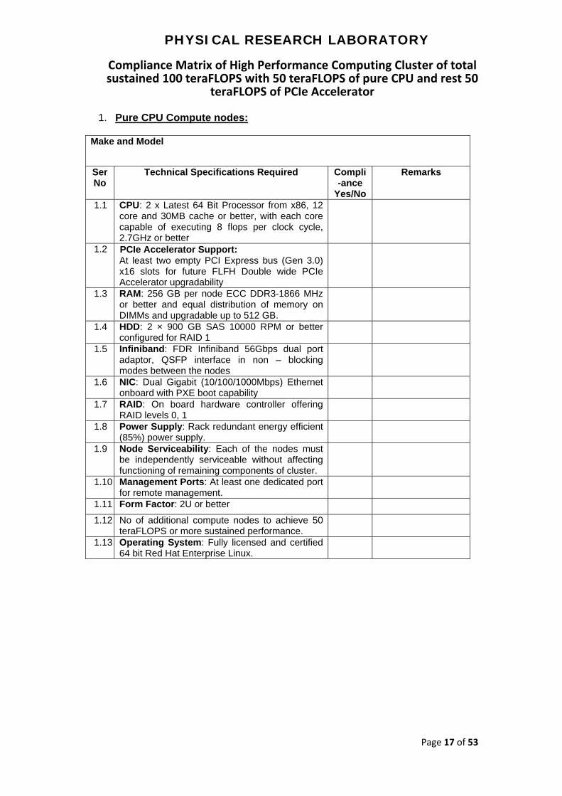
Compliance Matrix of High Performance Computing Cluster of total sustained 100 teraFLOPS with 50 teraFLOPS of pure CPU and rest 50
teraFLOPS of PCIe Accelerator
1. Pure CPU Compute nodes:
Make and Model
Ser No
Technical Specifications Required Compli-ance
Yes/No
Remarks
1.1 CPU: 2 x Latest 64 Bit Processor from x86, 12 core and 30MB cache or better, with each core capable of executing 8 flops per clock cycle, 2.7GHz or better
1.2 PCIe Accelerator Support: At least two empty PCI Express bus (Gen 3.0) x16 slots for future FLFH Double wide PCIe Accelerator upgradability
1.3 RAM: 256 GB per node ECC DDR3-1866 MHz or better and equal distribution of memory on DIMMs and upgradable up to 512 GB.
1.4 HDD: 2 × 900 GB SAS 10000 RPM or better configured for RAID 1
1.5 Infiniband: FDR Infiniband 56Gbps dual port adaptor, QSFP interface in non – blocking modes between the nodes
1.6 NIC: Dual Gigabit (10/100/1000Mbps) Ethernet onboard with PXE boot capability
1.7 RAID: On board hardware controller offering RAID levels 0, 1
1.8 Power Supply: Rack redundant energy efficient (85%) power supply.
1.9 Node Serviceability: Each of the nodes must be independently serviceable without affecting functioning of remaining components of cluster.
1.10 Management Ports: At least one dedicated port for remote management.
1.11 Form Factor: 2U or better
1.12 No of additional compute nodes to achieve 50 teraFLOPS or more sustained performance.
1.13 Operating System: Fully licensed and certified 64 bit Red Hat Enterprise Linux.
PHYSICAL RESEARCH LABORATORY
Page 18 of 53
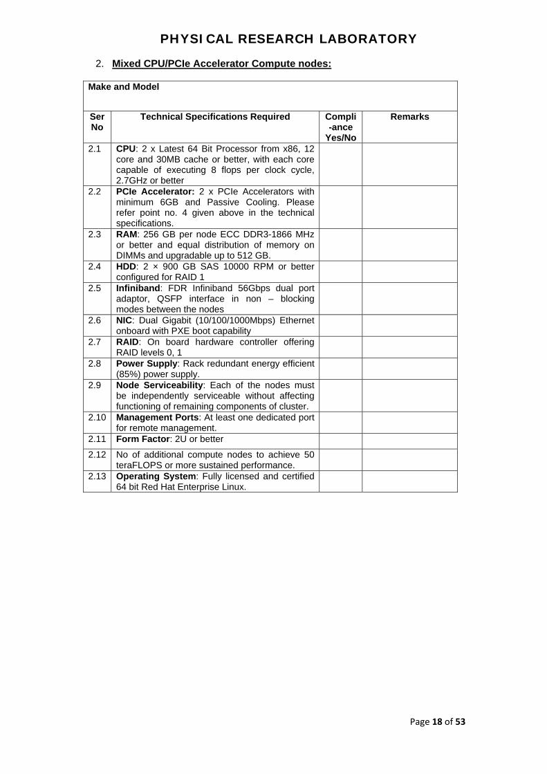
2. Mixed CPU/PCIe Accelerator Compute nodes:
Make and Model
Ser No
Technical Specifications Required Compli-ance
Yes/No
Remarks
2.1
CPU: 2 x Latest 64 Bit Processor from x86, 12 core and 30MB cache or better, with each core capable of executing 8 flops per clock cycle, 2.7GHz or better
2.2 PCIe Accelerator: 2 x PCIe Accelerators with minimum 6GB and Passive Cooling. Please refer point no. 4 given above in the technical specifications.
2.3 RAM: 256 GB per node ECC DDR3-1866 MHz or better and equal distribution of memory on DIMMs and upgradable up to 512 GB.
2.4 HDD: 2 × 900 GB SAS 10000 RPM or better configured for RAID 1
2.5 Infiniband: FDR Infiniband 56Gbps dual port adaptor, QSFP interface in non – blocking modes between the nodes
2.6 NIC: Dual Gigabit (10/100/1000Mbps) Ethernet onboard with PXE boot capability
2.7 RAID: On board hardware controller offering RAID levels 0, 1
2.8 Power Supply: Rack redundant energy efficient (85%) power supply.
2.9 Node Serviceability: Each of the nodes must be independently serviceable without affecting functioning of remaining components of cluster.
2.10 Management Ports: At least one dedicated port for remote management.
2.11 Form Factor: 2U or better
2.12 No of additional compute nodes to achieve 50 teraFLOPS or more sustained performance.
2.13 Operating System: Fully licensed and certified 64 bit Red Hat Enterprise Linux.

PHYSICAL RESEARCH LABORATORY
Page 19 of 53
3. Master Node with Redundancy HA mode
Make and Model
Ser
No
Technical Specifications Required Compli-ance
Yes/No
Remarks
3.1 CPU: 2 x Latest 64 Bit Processor from x86, 12 core and 30MB cache or better, with each core capable of executing 8 flops per clock cycle, 2.7GHz or better
3.2 PCIe Accelerator: 2 x PCIe Accelerators with minimum 6GB and Passive Cooling. Please refer point no. 4 given in the above technical specifications.
3.3 RAM: 256 GB per node ECC DDR3-1866 MHz or better and equal distribution of memory on DIMMs and upgradable up to 512 GB.
3.4 HDD: 2 × 900 GB SAS 10000 RPM or better configured for RAID 1
3.5 Infiniband: FDR Infiniband 56Gbps dual port adaptor, QSFP interface in non – blocking modes between the nodes
3.6 NIC: Dual Gigabit (10/100/1000Mbps) Ethernet onboard with PXE boot capability
3.7 RAID: On board hardware controller offering RAID levels 0, 1
3.8 Power Supply: Rack redundant energy efficient (85%) power supply.
3.9 Node Serviceability: Each of the nodes must be independently serviceable without affecting functioning of remaining components of cluster.
3.10 Management Ports: At least one dedicated port for remote management.
3.11 Form Factor: 2U or better
3.12 Operating System: Fully licensed and certified 64 bit Red Hat Enterprise Linux.

PHYSICAL RESEARCH LABORATORY
Page 20 of 53
4. Storage System and Storage Server:
Make and Model
Ser
No
Technical Specifications Required Compli-ance
Yes/No
Remarks
4.1 Disk Space: Minimum 300TB usable after RAID 5 (8+P) hardware based (PFS and NFS) dynamically configurable as per usage. Must be upgradable up to 1PB in same namespace with same throughput.
4.2 Storage Throughput (Read/Write): Concurrent 3GB/sec (or higher) write and 3GB/sec (or higher) read.
4.3 Cache: Minimum 16 GB across Active - Active Controller pair
4.4 Connectivity to Cluster: Storage must connect to cluster Infiniband network via storage servers
4.5 Reliability: The storage solution must have no single point failure
4.6 Management Software: Web based management software to monitor the health and status of the Storage System
4.7 Parallel File System Software: Parallel File System software must be commercially licensed and supported version from PFS software OEM.
4.8 Hierarchical Storage Management Software: Hierarchical Storage Management software (commercially licensed and supported by OEM) to move data from scratch to home and vice versa. This feature must be part a part of the base file system so that automation is enabled. A single console for data movement for the users and administrator must be provided
4.9 Storage System: Rack mountable with redundant and hot swap Power Supply
4.10 Storage Server(s): Rack mountable with redundant and hot swap Power Supply
4.11 Software: Commercial and OEM supported parallel file system configured to present entire storage as a single unified addressable namespace to HPC nodes.
4.12 Operating System: Fully licensed and certified 64 bit Red Hat Enterprise Linux.

PHYSICAL RESEARCH LABORATORY
Page 21 of 53
5. Backup Server with Backup Software:
Make and Model
Ser No
Technical Specifications Required Compli-ance
Yes/No
Remarks
5.1 CPU: 2 x Latest 64 Bit Processor from x86, 2.5GHz or better (4 core per processor or more)
5.2 RAM: 32 GB ECC DDR3-1866 MHz or better and expandable up to 128 GB
5.3 HDD: 2 x 900GB SAS, 10000 RPM or better in RAID-1, expandable to 8 HDDs and mounted on Hot-swap HDD bay
5.4 Interconnect: Dual Port FDR Adapter and 6Gb/s SAS HBAs to connect Tape Library
5.5 NIC: At least Four Gigabit Ethernet
5.6 Power Supply: Rack redundant energy efficient (85%) power supply.
5.7 Backup Software: Licensed and commercial Backup Software with RHEL support with required number of licenses for backup of 50 TB data and upgradable up to 300 TB data.
5.8 Operating System: Fully licensed and certified 64 bit Red Hat Enterprise Linux.
6. HPC Tape Library:
Make and Model
Ser No
Technical Specifications Required Compli-ance
Yes/No
Remarks
6.1 Drive: Min 4 x Half-high LTO6 SAS drives or better.
6.2 Number of Slots: Minimum 48 cartridge slots and min 3 mail slots
6.3 Data transfer rate (per drive): Up to 160 MBps native
6.4 Interface: 6Gb/s SAS
6.5 Management: Remote library management through a standard web interface, local LCD display and indicators for power, drive and activity, error status and message information.
6.6 Power Supply: Redundant power supply
6.7 Media: Minimum 200 x LTO6 RW Data Cartridges with 20 Universal Cleaning Cartridges.
6.8 Barcode Labels: 200 barcode labels for RW cartridges and 40 (starting with ‘CL’) for cleaning cartridges.

PHYSICAL RESEARCH LABORATORY
Page 22 of 53
7. Operating System
Ser No
Technical Specifications Required Compli-ance
Yes/No
Remarks
7.1 Fully licensed and certified latest (version 6.5 or above) 64 bit RHEL on all compute nodes
7.2 Fully licensed and certified latest (version 6.5 or above) 64 bit RHEL on HA master nodes
7.3 Fully licensed and certified latest (version 6.5 or above) 64 bit RHEL on storage server(s)
7.4 Fully licensed and certified latest (version 6.5 or above) 64 bit RHEL on backup server
8. Cluster Management Software
Make and Model
Ser No
Technical Specifications Required Compli-ance
Yes/No
Remarks
8.1 Cluster Management Software must support both PCIe Accelerator and CPU based hybrid cluster.
8.2 Software must handle all the nodes (compute and master) provided in the solutions.
8.3 OEM supported licensed suite.
8.4 GUI/Web based management.
8.5 Extensive cluster monitoring capability to drill down to node level performance parameters using GUI and with well-designed graphical reports for both PCIe Accelerator and CPU.
8.6 Management software must provide proactive notification of actual or impending component failure alerts.
8.7 Permission for only secure shell based access and a robust parallel execution shell implementation.
8.8 Licensed software for interconnect performance monitoring, communication management and cluster monitoring.
PHYSICAL RESEARCH LABORATORY
Page 23 of 53
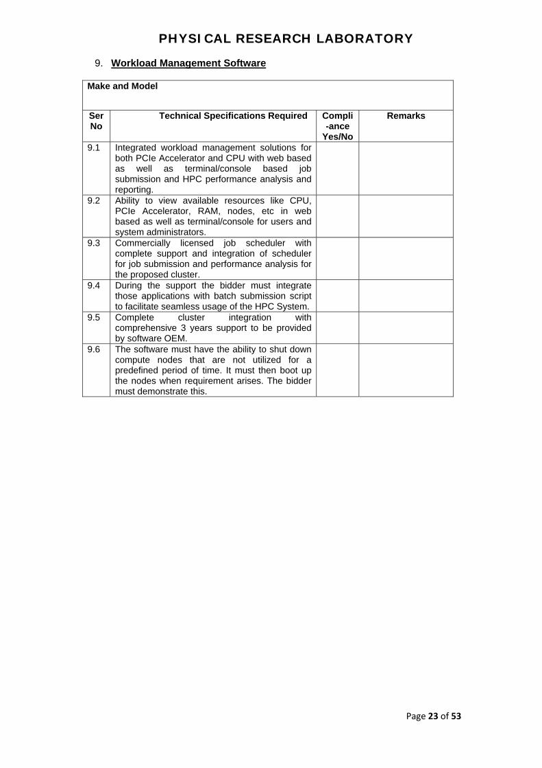
9. Workload Management Software
Make and Model
Ser No
Technical Specifications Required Compli-ance
Yes/No
Remarks
9.1 Integrated workload management solutions for both PCIe Accelerator and CPU with web based as well as terminal/console based job submission and HPC performance analysis and reporting.
9.2 Ability to view available resources like CPU, PCIe Accelerator, RAM, nodes, etc in web based as well as terminal/console for users and system administrators.
9.3 Commercially licensed job scheduler with complete support and integration of scheduler for job submission and performance analysis for the proposed cluster.
9.4 During the support the bidder must integrate those applications with batch submission script to facilitate seamless usage of the HPC System.
9.5 Complete cluster integration with comprehensive 3 years support to be provided by software OEM.
9.6 The software must have the ability to shut down compute nodes that are not utilized for a predefined period of time. It must then boot up the nodes when requirement arises. The bidder must demonstrate this.
PHYSICAL RESEARCH LABORATORY
Page 24 of 53
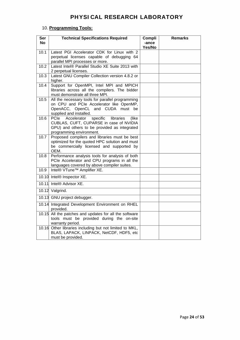
10. Programming Tools:
Ser No
Technical Specifications Required Compli-ance
Yes/No
Remarks
10.1 Latest PGI Accelerator CDK for Linux with 2 perpetual licenses capable of debugging 64 parallel MPI processes or more.
10.2 Latest Intel® Parallel Studio XE Suite 2013 with 2 perpetual licenses.
10.3 Latest GNU Compiler Collection version 4.8.2 or higher.
10.4 Support for OpenMPI, Intel MPI and MPICH libraries across all the compilers. The bidder must demonstrate all three MPI.
10.5 All the necessary tools for parallel programming on CPU and PCIe Accelerator like OpenMP, OpenACC, OpenCL and CUDA must be supplied and installed.
10.6 PCIe Accelerator specific libraries (like CUBLAS, CUFT, CUPARSE in case of NVIDIA GPU) and others to be provided as integrated programming environment.
10.7 Proposed compilers and libraries must be best optimized for the quoted HPC solution and must be commercially licensed and supported by OEM.
10.8 Performance analysis tools for analysis of both PCIe Accelerator and CPU programs in all the languages covered by above compiler suites.
10.9 Intel® VTune™ Amplifier XE.
10.10 Intel® Inspector XE.
10.11 Intel® Advisor XE.
10.12 Valgrind.
10.13 GNU project debugger.
10.14 Integrated Development Environment on RHEL provided.
10.15 All the patches and updates for all the software tools must be provided during the on-site warranty period.
10.16 Other libraries including but not limited to MKL, BLAS, LAPACK, LINPACK, NetCDF, HDF5, etc must be provided.

PHYSICAL RESEARCH LABORATORY
Page 25 of 53
11. UPS with Inbuilt batteries:
Make and Model
Ser No
Technical Specifications Required Compli-ance
Yes/No
Remarks
11.1 System capacity: Minimum 127kW N+1 Scalable to minimum 157KW.
11.2 Type of redundancy: N+1.
11.3 Backup time: 28-30 Minutes on the current full load.
General Specifications
11.4 This specification describes the operation and functionality of a continuous duty cycle, three-phase, solid-state, on-line double conversion static Uninterruptible Power System (UPS). The UPS must utilize a rack-mounted N+1 redundant, scalable and modular architecture.
11.5 Each UPS modules contains a full rated input rectifier / boost converter (hereafter referred to as Input Converter), full rated output inverter (KVA =KW), and battery charging circuit.
11.6 The system must comprise of a user-replaceable continuous duty bypass static switch module
11.7 The system must comprise of a user-replaceable hot swappable battery modules, which can be swapped without switching of the UPS modules when required.
11.8 The system must comprise of redundant main controller modules and redundant logic power supplies, which can be swapped without switching off any UPS modules whenever required.
11.9 Footprint of UPS and batteries together must be within 3000mm x 1070mm
11.10 Output Power Distribution: The UPS manufacturer must provide an internal output distribution system to distribute uninterrupted quality power for mission critical HPC solution load. Output distribution must be N+N from UPS to Rack PDUs. The output power must be distributed through 3 phase and neutral bus-duct. Modular hot scalable / swappable power distribution unit with provision to accommodate maximum 36 nos single pole or 12 nos of 3 pole or any combination of these MCBs of 16 amps, 32 amps and 63 amps rating for the UPS output power distribution. It must be possible to add or replace circuit breaker modules without switching off the complete load bus. If required, similar feature external power distribution system must be planned and implemented to provide power supply to all racks. At least 4 nos. of 3 pole or 12 nos. 1 pole MCBs slots must be provisioned for future expansion of server racks. All the required tray/ladders, factory made pre-cut cables / whips from the MCBs to Rack PDU

PHYSICAL RESEARCH LABORATORY
Page 26 of 53
sockets will be done by the bidder. Cabling can be done below floor or above racks as per the site feasibility.
11.11 Modes of Operations
11.12 Normal: The input converter and output inverter must operate in an on-line manner to continuously regulate power to the critical load. The input and output converters must be capable of full battery recharge while providing regulated power to the load simultaneously for all the lines and load conditions within the range of the UPS specifications.
11.13 Battery: Upon failure of the AC input source, the critical load must be supplied by the output inverter, which must derive its power from the battery system. There must be no interruption in power to the critical load during transfers to battery operation and back to normal.
11.14 Recharge: Upon restoration of the AC input source, the input converter and output inverter must simultaneously recharge the battery and provide regulated power to the critical load.
11.15 Static Bypass: The static bypass must be used to provide controller transfer of critical load from the inverter output to the bypass source. This transfer, along with its retransfer, must take place without power interruption to the critical load. In the event of an UPS output fault or significant output overload emergency, this transfer must be an automatic function. Manual transfer to the Static Bypass (called “Requested bypass”) must be available in order to facilitate a controlled transfer to Maintenance Bypass
11.16 Maintenance Bypass: The system can be equipped with an optional integrated and bus connected external make-before-break Maintenance Bypass Cabinet to electrically isolate the UPS during the routine maintenance and service of the UPS. The make-before-break Maintenance Bypass Cabinet must allow for the completely electrical isolation from the UPS. An option for an external make-before-break external maintenance bypass panel must be available
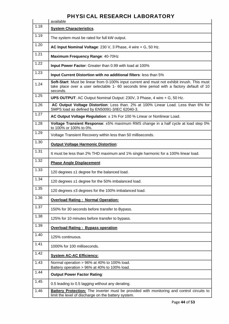
11.17 System Characteristics.
11.18 The system must be rated for full kW output.
11.19 AC Input Nominal Voltage: 230 V, 3 Phase, 4 wire + G, 50 Hz.
11.20 Maximum Frequency Range: 40-70Hz
11.21 Input Power Factor: Greater than 0.99 with load at 100%
11.22 Input Current Distortion with no additional filters: less than 5%
11.23 Soft-Start: Must be linear from 0-100% input current and must not exhibit inrush. This must take place over a user selectable 1- 60 seconds time period with a factory default of 10 seconds.
11.24 UPS OUTPUT: AC Output Nominal Output: 230V, 3 Phase, 4 wire + G, 50 Hz.
11.25 AC Output Voltage Distortion: Less than. 2%

PHYSICAL RESEARCH LABORATORY
Page 27 of 53
at 100% Linear Load. Less than 6% for SMPS load as defined by EN50091-3/IEC 62040-3.
11.26 AC Output Voltage Regulation: ±1% For 100 % Linear or Nonlinear Load.
11.27 Voltage Transient Response: ±5% maximum RMS change in a half cycle at load step 0% to 100% or 100% to 0%.
11.28 Voltage Transient Recovery within less than 50 milliseconds.
11.29 Output Voltage Harmonic Distortion:
11.30 It must be less than 2% THD maximum and 1% single harmonic for a 100% linear load.
11.31 Phase Angle Displacement:
11.32 120 degrees ±1 degree for the balanced load.
11.33 120 degrees ±1 degree for the 50% imbalanced load.
11.34 120 degrees ±3 degrees for the 100% imbalanced load.
11.35 Overload Rating : Normal Operation:
11.36 150% for 30 seconds before transfer to Bypass.
11.37 125% for 10 minutes before transfer to bypass.
11.38 Overload Rating : Bypass operation
11.39 125% continuous.
11.40 1000% for 100 milliseconds.
11.41 System AC-AC Efficiency:
11.42 Normal operation > 96% at 40% to 100% load. Battery operation > 96% at 40% to 100% load.
11.43 Output Power Factor Rating:
11.44 0.5 leading to 0.5 lagging without any derating.
11.45 Battery Protection: The inverter must be provided with monitoring and control circuits to limit the level of discharge on the battery system.
11.46 Charging:
11.47 The battery charging must keep the DC bus float voltage at ±1% of tolerance.
11.48 The battery charging circuit must contain a temperature compensation circuit, which will regulate the battery charging to optimize the battery life.
11.49 The battery charging circuit must remain active when in Static Bypass and also in the Normal Operation
11.50 Batteries:
11.51 The UPS battery must support an optional battery plant of modular construction made up of user replaceable, hot swappable, fused, battery modules. Each battery module must be monitored for the voltage and temperature during the UPS battery diagnostic. Battery charging current must be temperature compensated.
11.52 The battery jars housed within each removable battery module must be of the Valve Regulated Lead Acid (VRLA) type.
PHYSICAL RESEARCH LABORATORY
Page 28 of 53
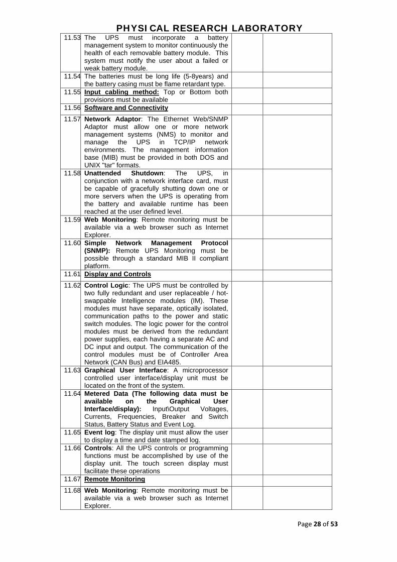
11.53 The UPS must incorporate a battery management system to monitor continuously the health of each removable battery module. This system must notify the user about a failed or weak battery module.
11.54 The batteries must be long life (5-8years) and the battery casing must be flame retardant type.
11.55 Input cabling method: Top or Bottom both provisions must be available
11.56 Software and Connectivity
11.57 Network Adaptor: The Ethernet Web/SNMP Adaptor must allow one or more network management systems (NMS) to monitor and manage the UPS in TCP/IP network environments. The management information base (MIB) must be provided in both DOS and UNIX "tar" formats.
11.58 Unattended Shutdown: The UPS, in conjunction with a network interface card, must be capable of gracefully shutting down one or more servers when the UPS is operating from the battery and available runtime has been reached at the user defined level.
11.59 Web Monitoring: Remote monitoring must be available via a web browser such as Internet Explorer.
11.60 Simple Network Management Protocol (SNMP): Remote UPS Monitoring must be possible through a standard MIB II compliant platform.
11.61 Display and Controls
11.62 Control Logic: The UPS must be controlled by two fully redundant and user replaceable / hot-swappable Intelligence modules (IM). These modules must have separate, optically isolated, communication paths to the power and static switch modules. The logic power for the control modules must be derived from the redundant power supplies, each having a separate AC and DC input and output. The communication of the control modules must be of Controller Area Network (CAN Bus) and EIA485.
11.63 Graphical User Interface: A microprocessor controlled user interface/display unit must be located on the front of the system.
11.64 Metered Data (The following data must be available on the Graphical User Interface/display): Input\Output Voltages, Currents, Frequencies, Breaker and Switch Status, Battery Status and Event Log.
11.65 Event log: The display unit must allow the user to display a time and date stamped log.
11.66 Controls: All the UPS controls or programming functions must be accomplished by use of the display unit. The touch screen display must facilitate these operations
11.67 Remote Monitoring
11.68 Web Monitoring: Remote monitoring must be available via a web browser such as Internet Explorer.

PHYSICAL RESEARCH LABORATORY
Page 29 of 53
11.69 RS232 Monitoring: Remote UPS monitoring must be possible via either RS232 or contact closure signals from the UPS.
11.70 Simple Network Management Protocol (SNMP): Remote UPS Monitoring must be possible through a standard MIB II compliant platform.
11.71 The UPS manufacturer must provide software to support graceful shutdown and remote monitoring
11.72 Environmental
11.73 Storage Ambient Temperature: -15°C to 40°C
11.74 Operating Ambient Temperature: 0°C to 40°C
11.75 Relative Humidity: 0 to 95% Non-condensing
11.76 Altitude: Maximum installation with no derating of the UPS output must be 3,000 feet (1000m) above the sea level.
11.77 Factory Assisted Start-Up and Maintenance
11.78 If a factory assisted UPS start-up is requested, factory trained service personnel must perform the following inspections, test procedures, and on-site training.
11.79 On-Site Operational Training: During the factory assisted start-up, operational training for site personnel must include touch screen operation, LED indicators, startup and shutdown procedures, maintenance bypass and AC disconnect operation, and alarm information.
11.80 The UPS manufacturer must have a nationwide service organization Available, consisting of manufacturer trained field service personnel to perform start-up, preventative maintenance, and service of the UPS system and power equipment. The service organization must offer 24X7 service support in Ahmedabad.
11.81 Replacement parts: Parts must be available through the nationwide service organization 365 days a year. The nationwide service organization must be capable of shipping parts / modules anywhere in India within the stipulated time required by us. PRL will not allow any component level repairs in UPS systems inside the HPC/UPS room.
11.82 Delivery Submittals
11.83 Installation manual: This includes instructions for storage, handling, examination, preparation, installation, and start-up of UPS.
11.84 User manual: This includes operating instructions.
11.85 OUTPUT Distribution
11.86 Modular and scalable distribution Units must be 42 U, half rack width and include casters and leveling feet to allow easy installation in the row. It should provide a means to level the equipment with adjacent IT racks.
11.87 All the output cables to each rack should be fed by the UPS and cooling units through this distribution panel only.

PHYSICAL RESEARCH LABORATORY
Page 30 of 53
11.88 All the cables from modular PDU are equipped with IEC 310 sockets
11.89 Modular PDUs must not need to schedule downtime to add a breaker, as modules (including circuit breaker, power cord, and power connection).
11.90 Warranty and Support
11.91 The Warranty must be offered directly from the OEM.
11.92 All other cables and accessories as required to make the project work as per the site requirement should be catered by the bidder and should be submitted along with the technical bid.
PHYSICAL RESEARCH LABORATORY
Page 31 of 53
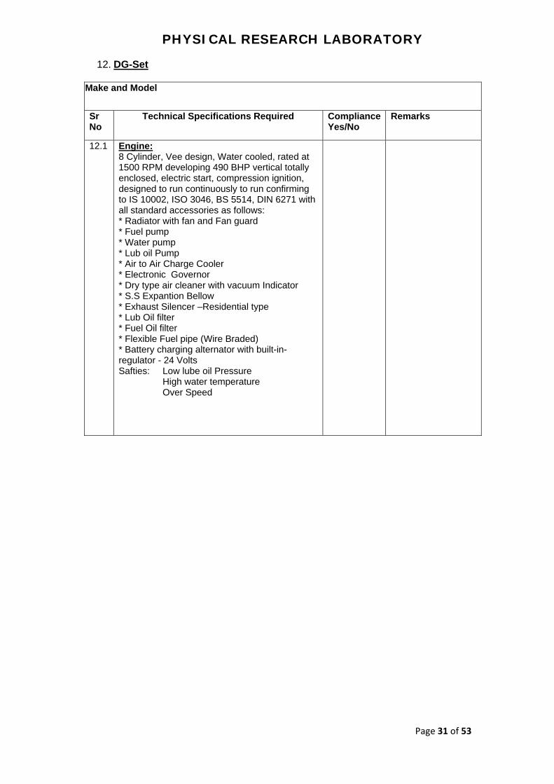
12. DG-Set
Make and Model
Sr No
Technical Specifications Required Compliance Yes/No
Remarks
12.1 Engine: 8 Cylinder, Vee design, Water cooled, rated at 1500 RPM developing 490 BHP vertical totally enclosed, electric start, compression ignition, designed to run continuously to run confirming to IS 10002, ISO 3046, BS 5514, DIN 6271 with all standard accessories as follows: * Radiator with fan and Fan guard * Fuel pump * Water pump * Lub oil Pump * Air to Air Charge Cooler * Electronic Governor * Dry type air cleaner with vacuum Indicator * S.S Expantion Bellow * Exhaust Silencer –Residential type * Lub Oil filter * Fuel Oil filter * Flexible Fuel pipe (Wire Braded) * Battery charging alternator with built-in-regulator - 24 Volts Safties: Low lube oil Pressure High water temperature Over Speed

PHYSICAL RESEARCH LABORATORY
Page 32 of 53
Microprocessor Based Engine Management System : Fully sequenced engine starting and stopping with clear LCD status messages. * Selectable manual or automatic starting modes. * Test mode with configurable runtime for ease of test compliance * Displays current operating value, and provides optional protections for: 1] Oil pressure. 2] Water or Oil Coolant temperature. 3] Fuel level. 4] Canopy Temperature. 5] Engine speed. 6] Battery voltage. 7] Coolant level status. 8] Charging status. 9] Engine running hours. *Message and Icon based warnings and alarms for: 1] Low oil pressure – Trip. 2] High engine temperature – Trip. 3] Low battery voltage – Indication. 4] Battery charge fail – Indication. 5] Over speed and under speed – Trip. 6] Coolant level – Trip. 7] Low Fuel – Indication. 8] Excitation – Indication.
Engines and Canopy Meets Central Pollution Control Boards Norms for Pollution
12.2 Alternator: Minimum 380KVA/304KW Alternator, suitable for continuous operation rated at 1500 rpm 415 V, 0.8 PF, 50Hz, 3Ph. in SPDP enclosure, self- excited and self- regulated, Brush less,H class of Insulation,IP 23 Class of Protection , floor mounted with Ball or Bearings on end shields. The alternator conforms to IS: 4722/BS/2613 and should be suitable for tropical condition
12.3 Fuel Tank: Min. 8 Hour Capacity, with Inlet and Outlet arrangement with air vent and drain plug arrangement
12.4 Base Frame: Suitable to couple with the above Engine and Alternator. The steel must be TISCO/SAIL make
12.5 Batteries: SF/ TATA GREEN Make 1No 12 V with 180Ah Leads and Battery Cable
12.6 Standard Control Panel:
Sheet steel made duly painted with stoving enamel paint consists of followings: * 1 No. MCB/MCCB of suitable rating . * 3Nos. Current Transformer * 2Nos. Indicating Lamps * 1Set Control Fuses

PHYSICAL RESEARCH LABORATORY
Page 33 of 53
12.7 Construction: The enclosure is modular in construction The enclosure is fabricated out of 1.6 mm thick cold annealed cold rolled (CRCA) sheet. Base frame is made of IS MC from the suitable sections / Sheet metal. Durable industrial locking system is provided on doors. Doors are gasketed with high quality EDPN gasket. Minimum 380 KVA Canopy size (LXWXH) 5700 x 2030 x 3440 mm approx. The canopies being offered are for output Noise level is 75 dB (A) at 1 meter average around the set inside canopy.
12.8 Corrosion Resistance: To make the enclosure weather proof: - All sheet metal parts/components are hot dip seven tanks pretreated and passivated. Sheet metal components are painted with P.P base powder coated CRCA Sheet. Base frame is epoxy coated. Zinc passivated hardware is used to avoid rusting.
12.9 Acoustic Insulation: Sound proofing of the enclosure done with foam confirming to IS-8183 of 64 kg/m3 density with 50 mm thickness. This is further secured with perforate Epoxy painted. Attenuates are provided to control sound at entry and exit to and from the container. Specially designed Residential Silencer is provided.
12.10 Ventilation and Air Circulation: Natural ventilation system for Water Cooled Engines as special radiator fan takes care of air changes inside canopy Exhaust pipe is thoroughly insulated by covering it with glass wooland further cladded in Enclosure.
12.11 Electrical: Neutral/Body earthing points at the sides of enclosure are isolated through Dough Moulded compound.
12.12 Safety: Following safeties are to be provided: - Emergency push button to stop the DG set from out side
12.13 Automatic Switchover: AMF Panel to be included for automatic Switching.
12.14 Installation and Integration: Supplier must install and integrate the entire DG-Set at our site including AMF panel, Power cabling, Change- over switch, cable, spring mounts, exhaust piping, earth pits and civil works required
12.15 Warranty: Onsite comprehensive warranty

PHYSICAL RESEARCH LABORATORY
Page 34 of 53
13. Cooling and A.C.
Make and Model
Ser No
Technical Specifications Required Compli-ance
Yes/No
Remarks
13.1 Row based Air Cooled Precision Cooling System capacity-29 KW per unit. At least 5 Machines with N+1 Redundancy configuration and Hot Aisle Containment System. Minimum IT load to cool is 127 KW.
13.2 Type of redundancy: N+1.
13.3 Cooling units must be placed in between two IT racks to follow horizontal airflow pattern i.e. cooling unit should supply cold air in front of rack and suck hot from rear end of it . However, Cooling units mustn’t be placed at the extreme end of the rows to avoid wastage of cold air and to provide effective cooling near to rack.
13.4 Supply temp to maintain at 23°C ± 1°C
13.5 Humidity control: At least 2 machines with built-in heater and humidifier for humidity control.
General Specifications.
13.6 Units must be 42 U, max. 600mm wide and include casters and leveling feet to allow ease of installation in the row and provide a means to level the equipment with adjacent IT racks.
13.7 The frame must be constructed of 16 gauge steel welded for maximum strength. All units must provide maintenance from the front and rear, allowing units to be placed within a row of racks.
13.8 Exterior panels must be 18 gauge steel with 80 kg/m3 density foam insulation. Insulation complies with UL94-5VA ASTM E84 flame spread and smoke developed rating of 25/50. Front and rear exterior panels must be 18 gauge perforated steel with 69.5% open free area, and equipped with a keyed lock to provide a means of securing access to the internal components of the unit.
FANS
13.9 1. Variable Speed Fans: The unit is equipped with
variable speed, electrically commutated, 400 mm backward incline fans complete with Inlet Volute.
2. Fan Protection: discharge finger guard. Outlet of the
fan must include a cage type finger guard. 3.Operation and Service: The unit must be capable of operation in the event of a fan failure.
Power Supply
13.10 Power Supplies: The unit must be provided with thermal-magnetic circuit breakers with interrupt capacity ratings per UL489/CSA C22.2/IEC-947. Units must include a main disconnect switch located on the electrical panel in order to disconnect the power input. A condenser disconnect must be field-supplied.

PHYSICAL RESEARCH LABORATORY
Page 35 of 53
Microprocessor Controller
13.11 Monitoring and configuration: The display interface must allow monitoring and configuration of the air conditioning unit through a menu-based control. Functions include status reporting, set-up, and temperature set points. Four LEDs report the operational status of the connected air conditioning unit.
13.12 Controls: The microprocessor controller must come equipped with control keys to allow the user to navigate between menus, select items, and input alpha numeric information.
13.13 Cable Water Detector A leak detection sensing cable must be shipped loose with the unit. If water or other conductive liquids contact the cable anywhere along its length, the main controller provides visual and audible alarm.
13.14 Alarms The microprocessor controller must activate a visible and audible alarm in the occurrence of the following events:
i) Cool Fail ii) Air filter clogged iii) Return air sensor fault iv) Supply air sensor fault v) Rack temperature sensor fault vi) High discharge pressure vii) Low suction pressure viii) Fan fault ix) Water detected x) Condensate pump fault xi) Air filter run hours violation xii) Group communication fault xiii) Supply air high temperature violation xiv) Return air high temperature violation xv) Filter DP sensor failure xvi) Suction pressure sensor failure xvii) Discharge pressure sensor failure xviii) Persistent high discharge pressure fault xix) Rack inlet temperature high violation xx) External communication fault xxi) Internal communication fault xxii) On standby input contact fault xxiii) A-link isolation relay fault xxiv) Excessive compressor cycling
For machine with Humidity control Machine additional alarms:-
i) Humidifier water conductivity high violation ii) Humidifier fault tolerance exceeded iii) Humidifier low water iv) Humidifier excessive output reduction v) Humidifier drain fault vi) Humidifier cylinder full vii) Humidifier replace cylinder viii) Humidifier RS485 communication fault ix) Humidity high/low violation x) Supply humidity sensor fault xi) Return humidity sensor fault xii) Heater fault xiii) Heater run hours exceeded
13.15 Network Management Card. The unit must include a Network Management Card to provide management
PHYSICAL RESEARCH LABORATORY
Page 36 of 53
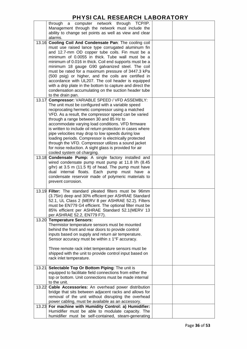
through a computer network through TCP/IP. Management through the network must include the ability to change set points as well as view and clear alarms.
13.16 Cooling Coil And Condensate Pan: The cooling coil must use raised lance type corrugated aluminum fin and 12.7-mm OD copper tube coils. Fin must be a minimum of 0.0055 in thick. Tube wall must be a minimum of 0.016 in thick. Coil end supports must be a minimum 18 gauge G90 galvanized steel. The coil must be rated for a maximum pressure of 3447.3 kPa (500 psig) or higher, and the coils are certified in accordance with UL207. The coil header is equipped with a drip plate in the bottom to capture and direct the condensation accumulating on the suction header tube to the drain pan.
13.17 Compressor: VARIABLE SPEED / VFD ASSEMBLY: The unit must be configured with a variable speed reciprocating hermetic compressor using a matched VFD. As a result, the compressor speed can be varied through a range between 30 and 85 Hz to accommodate varying load conditions. VFD firmware is written to include oil return protection in cases where pipe velocities may drop to low speeds during low loading periods. Compressor is electrically protected through the VFD. Compressor utilizes a sound jacket for noise reduction. A sight glass is provided for air cooled system oil charging.
13.18 Condensate Pump: A single factory installed and wired condensate pump must pump at 11.8 l/h (8.45 g/hr) at 3.5 m (11.5 ft) of head. The pump must have dual internal floats. Each pump must have a condensate reservoir made of polymeric materials to prevent corrosion.
13.19 Filter: The standard pleated filters must be 96mm (3.75in) deep and 30% efficient per ASHRAE Standard 52.1, UL Class 2 (MERV 8 per ASHRAE 52.2). Filters must be EN779 G4 efficient. The optional filter must be 85% efficient per ASHRAE Standard 52.1(MERV 13 per ASHRAE 52.2, EN779 F7).
13.20 Temperature Sensors: Thermistor temperature sensors must be mounted behind the front and rear doors to provide control inputs based on supply and return air temperature. Sensor accuracy must be within ± 1°F accuracy. Three remote rack inlet temperature sensors must be shipped with the unit to provide control input based on rack inlet temperature.
13.21 Selectable Top Or Bottom Piping: The unit is equipped to facilitate field connections from either the top or bottom. Unit connections must be made internal to the unit.
13.22 Cable Accessories: An overhead power distribution bridge that sits between adjacent racks and allows for removal of the unit without disrupting the overhead power cabling, must be available as an accessory.
13.23 For machine with Humidity Control: a) Humidifier: Humidifier must be able to modulate capacity. The humidifier must be self-contained, steam-generating
PHYSICAL RESEARCH LABORATORY
Page 37 of 53
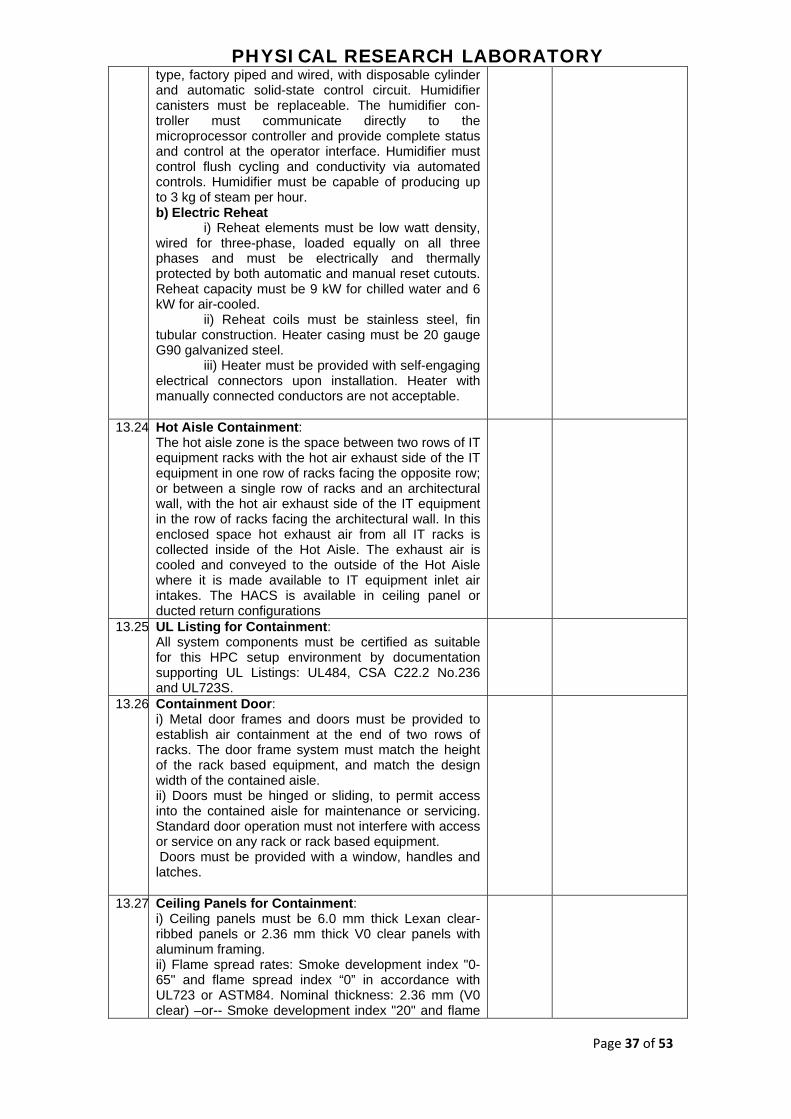
type, factory piped and wired, with disposable cylinder and automatic solid-state control circuit. Humidifier canisters must be replaceable. The humidifier con-troller must communicate directly to the microprocessor controller and provide complete status and control at the operator interface. Humidifier must control flush cycling and conductivity via automated controls. Humidifier must be capable of producing up to 3 kg of steam per hour. b) Electric Reheat i) Reheat elements must be low watt density, wired for three-phase, loaded equally on all three phases and must be electrically and thermally protected by both automatic and manual reset cutouts. Reheat capacity must be 9 kW for chilled water and 6 kW for air-cooled. ii) Reheat coils must be stainless steel, fin tubular construction. Heater casing must be 20 gauge G90 galvanized steel. iii) Heater must be provided with self-engaging electrical connectors upon installation. Heater with manually connected conductors are not acceptable.
13.24 Hot Aisle Containment: The hot aisle zone is the space between two rows of IT equipment racks with the hot air exhaust side of the IT equipment in one row of racks facing the opposite row; or between a single row of racks and an architectural wall, with the hot air exhaust side of the IT equipment in the row of racks facing the architectural wall. In this enclosed space hot exhaust air from all IT racks is collected inside of the Hot Aisle. The exhaust air is cooled and conveyed to the outside of the Hot Aisle where it is made available to IT equipment inlet air intakes. The HACS is available in ceiling panel or ducted return configurations
13.25 UL Listing for Containment: All system components must be certified as suitable for this HPC setup environment by documentation supporting UL Listings: UL484, CSA C22.2 No.236 and UL723S.
13.26 Containment Door: i) Metal door frames and doors must be provided to establish air containment at the end of two rows of racks. The door frame system must match the height of the rack based equipment, and match the design width of the contained aisle. ii) Doors must be hinged or sliding, to permit access into the contained aisle for maintenance or servicing. Standard door operation must not interfere with access or service on any rack or rack based equipment. Doors must be provided with a window, handles and latches.
13.27 Ceiling Panels for Containment: i) Ceiling panels must be 6.0 mm thick Lexan clear-ribbed panels or 2.36 mm thick V0 clear panels with aluminum framing. ii) Flame spread rates: Smoke development index "0-65" and flame spread index “0” in accordance with UL723 or ASTM84. Nominal thickness: 2.36 mm (V0 clear) –or-- Smoke development index "20" and flame

PHYSICAL RESEARCH LABORATORY
Page 38 of 53
spread index "0" in accordance with UL723 or ASTM84. Nominal thickness: 6.0 mm (Lexan) .Minimum Light Transmission per ASTM D1003 equal to 82% or greater.

PHYSICAL RESEARCH LABORATORY
Page 39 of 53
14. HPC Racks and Rack PDUs:
Make and Model
Ser No
Technical Specifications Required Complia-nce
Yes/No
Remarks
14.1 HPC Server Racks Minimum Qty 7 no.
14.2 42U Server racks
14.3 Maximum Height of the rack along with Casters mustn't be more than 1995 mm
14.4 Minimum Width of the rack must be 600mm
14.5 Depth of the rack must be at least 1070mm or more
14.6 Weight Carrying Capacity (static load) must be more than 1360 kg and (dynamic load) must be more than 1020 kg
14.7 Rack Hardware mounting Frame Width 19"
14.8 Color must be Black
14.9 Front door must be perforated single and rear doors must be perforated split doors
14.10 Guage Ratings of rack material is as below: Vertical Posts - 16 gauge Front Door - 16 gauge Rear Door - 18 gauge Roof - 18 gauge EIA Mounting Rails - 14 gauge Side Panels – 18 gauge
14.11 Weight of the rack 125Kg or more
14.12 Side Panel with single point locking with quick release latches
14.13 Rack must have Regulatory Approvals/Standards: - UL 60950-1 , EIA-310-E
14.14 Perforation pattern for Front door must be 66% and for rear doors it must be 74% at least
14.15 Rack must include - Vertical Cable managers on both the sides, Earth Kit, Casters and Levelers, Mounting Hardware, Baying Hardware kit
14.16 Rack must have Cable access openings with pre-installed brushes in the roof
14.17 Rack must be factory fitted and completely assembled rack must come to site
14.18 Rack must have one temperature and humidity sensor per rack
14.19 There must be lock and key facility for both - front and back doors and side panels
14.20 Rack must have cable entry opening in the roof of the rack as also from the bottom along with the brush strips. Cable entry cut must be both on the left and right hand side.
14.21 Rack must have cable routing accessories on top of the rack for Data and Power cables
14.22 Standard Warranty on Rack must be minimum 5 years repair or replace
14.23 Metered IP RACK PDUs : Qty 2 per Rack a) 22KW three phase Metered, zero U
PDU, with at least IEC 320 C13 (5
PHYSICAL RESEARCH LABORATORY
Page 40 of 53
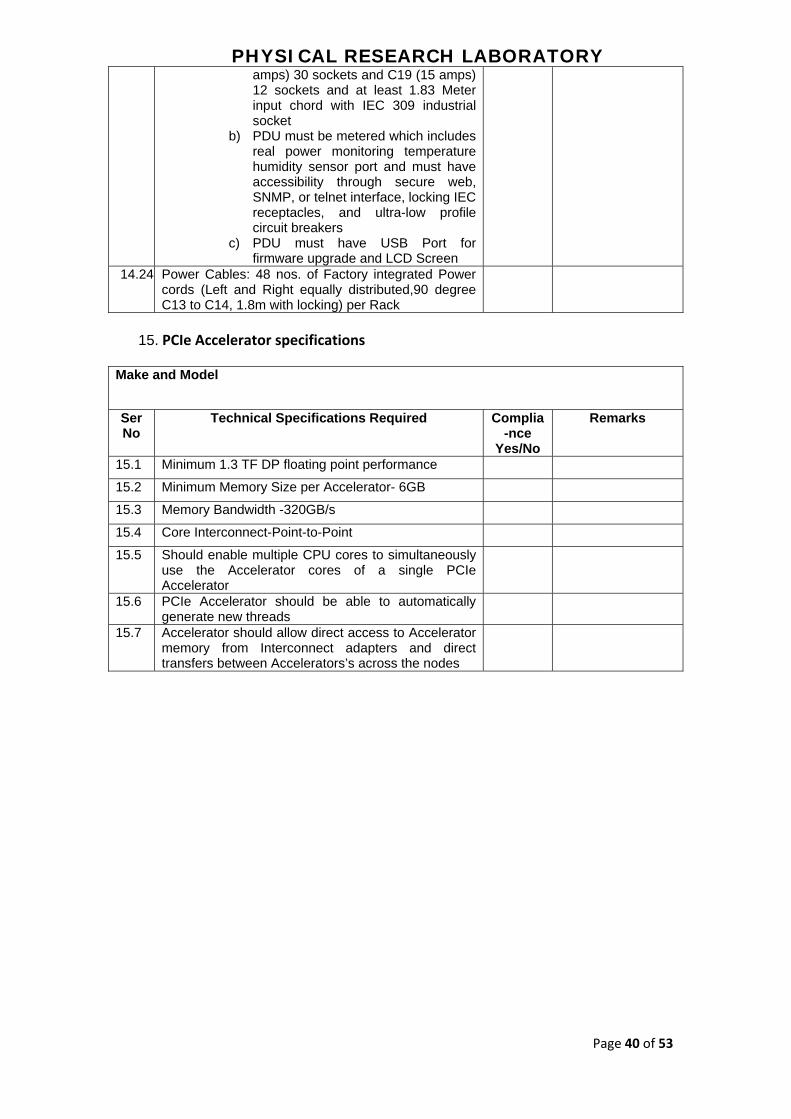
amps) 30 sockets and C19 (15 amps) 12 sockets and at least 1.83 Meter input chord with IEC 309 industrial socket
b) PDU must be metered which includes real power monitoring temperature humidity sensor port and must have accessibility through secure web, SNMP, or telnet interface, locking IEC receptacles, and ultra-low profile circuit breakers
c) PDU must have USB Port for firmware upgrade and LCD Screen
14.24 Power Cables: 48 nos. of Factory integrated Power cords (Left and Right equally distributed,90 degree C13 to C14, 1.8m with locking) per Rack
15. PCIe Accelerator specifications
Make and Model
Ser No
Technical Specifications Required Complia-nce
Yes/No
Remarks
15.1 Minimum 1.3 TF DP floating point performance
15.2 Minimum Memory Size per Accelerator- 6GB
15.3 Memory Bandwidth -320GB/s
15.4 Core Interconnect-Point-to-Point
15.5 Should enable multiple CPU cores to simultaneously use the Accelerator cores of a single PCIe Accelerator
15.6 PCIe Accelerator should be able to automatically generate new threads
15.7 Accelerator should allow direct access to Accelerator memory from Interconnect adapters and direct transfers between Accelerators’s across the nodes

PHYSICAL RESEARCH LABORATORY
Page 41 of 53
Annexure I: HPC room

PHYSICAL RESEARCH LABORATORY
Page 42 of 53
Annexure II: Computer Centre

PHYSICAL RESEARCH LABORATORY
Page 43 of 53
Annexure III: UPS with Inbuilt Batteries
Ser No
Technical Specifications Required
1.1
System capacity: Minimum 127kW N+1 Scalable up to minimum 157KW.
1.2
Type of redundancy: N+1.
1.3
Backup time: 28-30 Minutes on the current full load.
1.4
General Specifications
1.5
This specification describes the operation and functionality of a continuous duty cycle, three-phase, solid-state, on-line double conversion static Uninterruptible Power System (UPS). The UPS must utilize a rack-mounted N+1 redundant, scalable and modular architecture.
1.6
Each UPS modules contains a full rated input rectifier / boost converter (hereafter referred to as Input Converter), full rated output inverter (KVA =KW), and battery charging circuit.
1.7
The system must comprise of a user-replaceable continuous duty bypass static switch module
1.8
The system must comprise of a user-replaceable hot swappable battery modules, which can be swapped without switching of the UPS modules when required.
1.9
The system must comprise of redundant main controller modules, redundant logic power supplies, which can be swapped without switching off any UPS modules when required.
1.10 Footprint of UPS and batteries together must be within 3000mm x 1070mm
1.11
Output Power Distribution: The UPS manufacturer must provide an internal output distribution system to distribute uninterrupted quality power for mission critical HPC solution load. Output distribution must be N+N from UPS to Rack PDUs. The output power must be distributed through 3 phase and neutral bus-duct. Modular hot scalable / swappable power distribution unit with provision to accommodate maximum 36 nos single pole or 12 nos of 3 pole or any combination of these MCBs of 16 amps, 32 amps and 63 amps rating for the UPS output power distribution. It must be possible to add or replace circuit breaker modules without switching off the complete load bus. If required, similar feature external power distribution system must be planned and implemented to provide power supply to all racks. At least 4 nos. of 3 pole or 12 nos. 1 pole MCBs slots must be provisioned for future expansion of server racks. All the required tray/ladders, factory made pre-cut cables/whips from the MCBs to Rack PDU sockets will be done by the bidder. Cabling can be done below floor or above racks as per the site feasibility.
1.12
Modes of Operations
1.13
Normal: The input converter and output inverter must operate in an on-line manner to continuously regulate power to the critical load. The input and output converters must be capable of full battery recharge while providing regulated power to the load simultaneously for all the lines and load conditions within the range of the UPS specifications.
1.14
Battery: Upon failure of the AC input source, the critical load must be supplied by the output inverter, which must derive its power from the battery system. There must be no interruption in power to the critical load during transfers to battery operation and back to normal operation.
1.15
Recharge: Upon restoration of the AC input source, the input converter and output inverter must simultaneously recharge the battery and provide regulated power to the critical load.
1.16
Static Bypass: The static bypass must be used to provide controller transfer of critical load from the inverter output to the bypass source. This transfer, along with its retransfer, must take place without power interruption to the critical load. In the event of an UPS output fault or significant output overload emergency, this transfer must be an automatic function. Manual transfer to the Static Bypass (called “Requested bypass”) must be available in order to facilitate a controlled transfer to Maintenance Bypass
1.17
Maintenance Bypass: The system can be equipped with an optional integrated and bus connected external make-before-break Maintenance Bypass Cabinet to electrically isolate the UPS during the routine maintenance and service of the UPS. The make-before-break Maintenance Bypass Cabinet must allow for the completely electrical isolation from the UPS. An option for an external make-before-break external maintenance bypass panel must be
PHYSICAL RESEARCH LABORATORY
Page 44 of 53
available 1.18
System Characteristics.
1.19
The system must be rated for full kW output.
1.20
AC Input Nominal Voltage: 230 V, 3 Phase, 4 wire + G, 50 Hz.
1.21
Maximum Frequency Range: 40-70Hz
1.22
Input Power Factor: Greater than 0.99 with load at 100%
1.23
Input Current Distortion with no additional filters: less than 5%
1.24
Soft-Start: Must be linear from 0-100% input current and must not exhibit inrush. This must take place over a user selectable 1- 60 seconds time period with a factory default of 10 seconds.
1.25
UPS OUTPUT: AC Output Nominal Output: 230V, 3 Phase, 4 wire + G, 50 Hz.
1.26
AC Output Voltage Distortion: Less than. 2% at 100% Linear Load. Less than 6% for SMPS load as defined by EN50091-3/IEC 62040-3.
1.27
AC Output Voltage Regulation: ± 1% For 100 % Linear or Nonlinear Load.
1.28
Voltage Transient Response: ±5% maximum RMS change in a half cycle at load step 0% to 100% or 100% to 0%.
1.29
Voltage Transient Recovery within less than 50 milliseconds.
1.30
Output Voltage Harmonic Distortion:
1.31
It must be less than 2% THD maximum and 1% single harmonic for a 100% linear load.
1.32
Phase Angle Displacement:
1.33
120 degrees ±1 degree for the balanced load.
1.34
120 degrees ±1 degree for the 50% imbalanced load.
1.35
120 degrees ±3 degrees for the 100% imbalanced load.
1.36
Overload Rating : Normal Operation:
1.37
150% for 30 seconds before transfer to Bypass.
1.38
125% for 10 minutes before transfer to bypass.
1.39
Overload Rating : Bypass operation
1.40
125% continuous.
1.41
1000% for 100 milliseconds.
1.42
System AC-AC Efficiency:
Normal operation > 96% at 40% to 100% load. 1.43 Battery operation > 96% at 40% to 100% load. 1.44
Output Power Factor Rating:
1.45
0.5 leading to 0.5 lagging without any derating.
1.46
Battery Protection: The inverter must be provided with monitoring and control circuits to limit the level of discharge on the battery system.

PHYSICAL RESEARCH LABORATORY
Page 45 of 53
1.47
Charging
1.48
The battery charging must keep the DC bus float voltage at ±1% of tolerance.
1.49
The battery charging circuit must contain a temperature compensation circuit, which must regulate the battery charging to optimize the battery life.
1.50
The battery charging circuit must remain active when in Static Bypass and also in the Normal Operation.
1.51
Batteries
1.52
The UPS battery must support an optional battery plant of modular construction made up of user replaceable, hot swappable, fused, battery modules. Each battery module must be monitored for the voltage and temperature during the UPS battery diagnostic. Battery charging current must be temperature compensated.
1.53
The battery jars housed within each removable battery module must be of the Valve Regulated Lead Acid (VRLA) type.
1.54
The UPS must incorporate a battery management system to monitor continuously the health of each removable battery module. This system must notify the user about a failed or weak battery module.
1.55
The batteries must be long life (5-8years) and the battery casing must be flame retardant type.
1.56
Input cabling Method: Top or Bottom both provisions must be available
1.57
Software and Connectivity
1.58
Network Adaptor: The Ethernet Web/SNMP Adaptor must allow one or more network management systems (NMS) to monitor and manage the UPS in TCP/IP network environments. The management information base (MIB) must be provided in both DOS and UNIX "tar" formats.
1.59
Unattended Shutdown: The UPS, in conjunction with a network interface card, must be capable of gracefully shutting down one or more servers when the UPS is operating from the battery and available runtime has been reached at the user defined level.
1.60
Web Monitoring: Remote monitoring must be available via a web browser such as Internet Explorer.
1.61
Simple Network Management Protocol (SNMP): Remote UPS Monitoring must be possible through a standard MIB II compliant platform
1.62
Display and Controls
1.63
Control Logic: The UPS must be controlled by two fully redundant and user replaceable / hot-swappable Intelligence modules (IM). These modules must have separate, optically isolated, communication paths to the power and static switch modules. The logic power for the control modules must be derived from the redundant power supplies, each having a separate AC and DC input and output. The communication of the control modules must be of Controller Area Network (CAN Bus) and EIA485
1.64
Graphical User Interface: A microprocessor controlled user interface/display unit must be located on the front of the system.
1.65
Metered Data (The following data must be available on the Graphical User Interface/display): Input\Output Voltages, Currents, Frequencies, Breaker and Switch Status, Battery Status and Event Log.
1.66
Event log: The display unit must allow the user to display a time and date stamped log.
1.67
Controls: All the UPS controls or programming functions must be accomplished by use of the display unit. The touch screen display must facilitate these operations
1.68
Remote Monitoring
1.69
Web Monitoring: Remote monitoring must be available via a web browser such as Internet Explorer.
1.70
RS232 Monitoring: Remote UPS monitoring must be possible via either RS232 or contact closure signals from the UPS.
1.71 Simple Network Management Protocol (SNMP): Remote UPS Monitoring must be

PHYSICAL RESEARCH LABORATORY
Page 46 of 53
possible through a standard MIB II compliant platform. 1.72
The UPS manufacturer must provide software to support graceful shutdown and remote monitoring.
1.73
Environmental
1.74
Storage Ambient Temperature: -15°C to 40°C.
1.75
Operating Ambient Temperature: 0°C to 40°C.
1.76
Relative Humidity: 0 to 95% Non-condensing
1.77
Altitude: Maximum installation with no derating of the UPS output must be 3,000 feet (1000m) above the sea level.
1.78
Factory Assisted Start-Up and Maintenance
1.79
If a factory assisted UPS start-up is requested, factory trained service personnel must perform the following inspections, test procedures, and on-site training:
1.80
On-Site Operational Training: During the factory assisted start-up, operational training for site personnel must include touch screen operation, LED indicators, startup and shutdown procedures, maintenance bypass and AC disconnect operation, and alarm information.
1.81
The UPS manufacturer must have a nationwide service organization Available, consisting of manufacturer trained field service personnel to perform start-up, preventative maintenance, and service of the UPS system and power equipment. The service organization must offer 24X7 service support in Ahmedabad
1.82
Replacement parts: Parts must be available through the nationwide service organization 365 days a year. The nationwide service organization must be capable of shipping parts / modules anywhere in India within the stipulated time required by us. PRL will not allow any component level repairs in UPS systems inside the HPC/UPS room.
1.86
Delivery Submittals
1.87
Installation manual: This includes instructions for storage, handling, examination, preparation, installation, and start-up of UPS.
1.88
User manual: This includes operating instructions.
1.89
OUTPUT Distribution:
1.90
Modular and scalable distribution Units must be 42 U, half rack width and include casters and leveling feet to allow ease of installation in the row and provide a means to level the equipment with adjacent IT racks.
1.91
All the output cables to the each rack must be fed by the UPS and cooling units through this distribution panel only.
1.92
All the cables from modular PDU are equipped with IEC 310 sockets.
1.93
Modular PDUs must not need to schedule downtime to add a breaker, as modules (including circuit breaker, power cord, and power connection).
1.94
Warranty and Support
1.95
The Warranty must be offered directly from the OEM.
1.96
All other cables and accessories as required to make the project work as per the site requirement must be catered by the bidder and must be submitted along with the technical bid.

PHYSICAL RESEARCH LABORATORY
Page 47 of 53
Annexure IV: DG‐Set
Sr No
Parameter Configuration
1 General COMPLETE Silent Diesel Generating Set factory assembled, pre-aligned and pre-tested DIESEL GENERATOR SET having Following Specification 8 Cylinder, Vee design, Water cooled, rated at 1500 RPM developing 490 BHP vertical totally enclosed, electric start, compression ignition, designed to run continuously to run confirming to IS 10002, ISO 3046, BS 5514, DIN 6271 with all standard accessories as follows: * Radiator with fan and Fan guard * Fuel pump * Water pump * Lub oil Pump * Air to Air Charge Cooler * Electronic Governor * Dry type air cleaner with vacuum Indicator * S.S Expantion Bellow * Exhaust Silencer –Residential type * Lub Oil filter * Fuel Oil filter * Flexible Fuel pipe (Wire Braded) * Battery charging alternator with built-in-regulator - 24 Volts Safties: Low lube oil Pressure High water temperature Over Speed
Microprocessor Based Engine Management System : Fully sequenced engine starting and stopping with clear LCD status messages. * Selectable manual or automatic starting modes. * Test mode with configurable runtime for ease of test compliance * Displays current operating value, and provides optional protections for: 1] Oil pressure. 2] Water or Oil Coolant temperature. 3] Fuel level. 4] Canopy Temperature. 5] Engine speed. 6] Battery voltage. 7] Coolant level status. 8] Charging status. 9] Engine running hours. * Message and Icon based warnings and alarms for: 1] Low oil pressure – Trip. 2] High engine temperature – Trip. 3] Low battery voltage – Indication. 4] Battery charge fail – Indication. 5] Over speed and under speed – Trip. 6] Coolant level - Trip. 7] Low Fuel – Indication. 8] Excitation – Indication.
2 ENGINE
Engines and Canopy Meets Central Pollution Control Boards Norms for
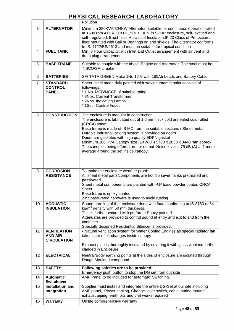
PHYSICAL RESEARCH LABORATORY
Page 48 of 53
Pollution
3 ALTERNATOR Minimum 380KVA/304KW Alternator, suitable for continuous operation rated at 1500 rpm 415 V, 0.8 PF, 50Hz, 3Ph. in SPDP enclosure, self- excited and self- regulated, Brush less,H class of Insulation,IP 23 Class of Protection , floor mounted with Ball or Bearings on end shields. The alternator conforms to IS: 4722/BS/2613 and must be suitable for tropical condition
4 FUEL TANK Min. 8 Hour Capacity, with Inlet and Outlet arrangement with air vent and drain plug arrangement
5 BASE FRAME Suitable to couple with the above Engine and Alternator. The steel must be TISCO/SAIL make
6 BATTERIES SF/ TATA GREEN Make 1No 12 V with 180Ah Leads and Battery Cable
7 STANDARD CONTROL PANEL
Sheet steel made duly painted with stoving enamel paint consists of followings: * 1 No. MCB/MCCB of suitable rating . * 3Nos. Current Transformer * 2Nos. Indicating Lamps * 1Set Control Fuses
8 CONSTRUCTION The enclosure is modular in construction The enclosure is fabricated out of 1.6 mm thick cold annealed cold rolled (CRCA) sheet. Base frame is made of IS MC from the suitable sections / Sheet metal. Durable industrial locking system is provided on doors Doors are gasketed with high quality EDPN gasket Minimum 380 KVA Canopy size (LXWXH) 5700 x 2030 x 3440 mm approx. The canopies being offered are for output Noise level is 75 dB (A) at 1 meter average around the set inside canopy
9 CORROSION RESISTANCE
To make the enclosure weather proof: - All sheet metal parts/components are hot dip seven tanks pretreated and passivated. Sheet metal components are painted with P.P base powder coated CRCA Sheet. Base frame is epoxy coated. Zinc passivated hardware is used to avoid rusting.
10 ACOUSTIC INSULATION
Sound proofing of the enclosure done with foam confirming to IS-8183 of 64 kg/m3 density with 50 mm thickness. This is further secured with perforate Epoxy painted Attenuates are provided to control sound at entry and exit to and from the container. Specially designed Residential Silencer is provided.
11 VENTILATION AND AIR CIRCULATION
• Natural ventilation system for Water Cooled Engines as special radiator fan takes care of air changes inside canopy Exhaust pipe is thoroughly insulated by covering it with glass wooland further cladded in Enclosure.
12 ELECTRICAL Neutral/Body earthing points at the sides of enclosure are isolated through Dough Moulded compound.
13 SAFETY Following safeties are to be provided: Emergency push button to stop the DG set from out side
14 Automatic Switchover
AMF Panel to be included for automatic Switching.
15 Installation and Integration
Supplier must install and integrate the entire DG-Set at our site including AMF panel, Power cabling, Change- over switch, cable, spring mounts, exhaust piping, earth pits and civil works required
16 Warranty Onsite comprehensive warranty

PHYSICAL RESEARCH LABORATORY
Page 49 of 53
Annexure V: Cooling with Accessories
Ser No Technical Specifications Required
1.1
Row based Air Cooled Precision Cooling System capacity-29 KW per unit. At least 5 Machines with N+1 Redundancy configuration and Hot Aisle Containment System. Minimum IT load to cool is 127KW
1.2
Type of redundancy: N+1.
1.3
Cooling units must be placed in between two IT racks to follow horizontal airflow pattern i.e. cooling unit must supply cold air in front of rack and suck hot from rear end of it . However, Cooling units mustn’t be placed at the extreme end of the rows to avoid wastage of cold air and to provide effective cooling near to rack.
1.4
Supply temp to maintain: at 23°C ± 1°C.
1.5
Humidity control: At least 2 machines with built-in heater and humidifier for humidity control.
1.6
General Specifications.
1.7
Units must be 42 U, max. 600mm wide and include casters and leveling feet to allow ease of installation in the row and provide a means to level the equipment with adjacent IT racks.
1.8
The frame must be constructed of 16 gauge steel welded for maximum strength. All units must provide maintenance from the front and rear, allowing units to be placed within a row of racks.
1.9
Exterior panels must be 18 gauge steel with 80 kg/m3 density foam insulation. Insulation complies with UL94-5VA ASTM E84 flame spread and smoke developed rating of 25/50. Front and rear exterior panels must be 18 gauge perforated steel with 69.5% open free area, and equipped with a keyed lock to provide a means of securing access to the internal components of the unit.
1.10
FANS
1. Variable Speed Fans: The unit is equipped with variable speed, electrically
commutated, 400 mm backward incline fans complete with Inlet Volute.
2. Fan Protection: discharge finger guard. Outlet of the fan must include a cage type finger guard. 3.Operation and Service: The unit must be capable of operation in the event
of a fan failure.
1.11
1.12
Power Supply
Power Supplies: The unit must be provided with thermal-magnetic circuit breakers with interrupt
1.13 capacity ratings per UL489/CSA C22.2/IEC-947. Units must include a main disconnect
switch located on the electrical panel in order to disconnect the power input. A condenser disconnect must be field-supplied.
1.14
Microprocessor Controller
Monitoring and configuration: The display interface must allow monitoring and configuration of the air conditioning unit through a menu-based control. 1.15
Functions include status reporting, set-up, and temperature set points. Four LEDs report the operational status of the connected air conditioning unit.
1.16
Controls: The microprocessor controller must come equipped with control keys to allow the user to navigate between menus, select items, and input alpha numeric information.
1.17
Cable Water Detector A leak detection sensing cable must be shipped loose with the unit. If water or other conductive liquids contact the cable anywhere along its length, the main controller provides visual and audible alarm.
1.18
Alarms The microprocessor controller must activate a visible and audible alarm in the occurrence of the following events:

PHYSICAL RESEARCH LABORATORY
Page 50 of 53
xxv) Cool Fail xxvi) Air filter clogged xxvii) Return air sensor fault xxviii) Supply air sensor fault xxix) Rack temperature sensor fault xxx) High discharge pressure xxxi) Low suction pressure xxxii) Fan fault xxxiii) Water detected xxxiv) Condensate pump fault xxxv) Air filter run hours violation xxxvi) Group communication fault xxxvii) Supply air high temperature violation xxxviii) Return air high temperature violation xxxix) Filter DP sensor failure xl) Suction pressure sensor failure xli) Discharge pressure sensor failure xlii) Persistent high discharge pressure fault xliii) Rack inlet temperature high violation xliv) External communication fault xlv) Internal communication fault xlvi) On standby input contact fault xlvii) A-link isolation relay fault xlviii) Excessive compressor cycling
For machine with Humidity control Machine additional alarms:-
xiv) Humidifier water conductivity high violation xv) Humidifier fault tolerance exceeded xvi) Humidifier low water xvii) Humidifier excessive output reduction xviii) Humidifier drain fault xix) Humidifier cylinder full xx) Humidifier replace cylinder xxi) Humidifier RS485 communication fault xxii) Humidity high/low violation xxiii) Supply humidity sensor fault xxiv) Return humidity sensor fault xxv) Heater fault xxvi) Heater run hours exceeded
1.20
Network Management Card. The unit must include a Network Management Card to provide management through a computer network through TCP/IP. Management through the network must include the ability to change set points as well as view and clear alarms.
1.21
Cooling Coil And Condensate Pan: The cooling coil must use raised lance type corrugated aluminum fin and 12.7-mm OD copper tube coils. Fin must be a minimum of 0.0055 in thick. Tube wall must be a minimum of 0.016 in thick. Coil end supports must be a minimum 18 gauge G90 galvanized steel. The coil must be rated for a maximum pressure of 3447.3 kPa (500 psig) or higher, and the coils are certified in accordance with UL207. The coil header is equipped with a drip plate in the bottom to capture and direct the condensation accumulating on the suction header tube to the drain pan. Compressor: VARIABLE SPEED / VFD ASSEMBLY:
1.22
The unit must be configured with a variable speed reciprocating hermetic compressor using a matched VFD. As a result, the compressor speed can be varied through a range between 30 and 85 Hz to accommodate varying load conditions. VFD firmware is written to include oil return protection in cases where pipe velocities may drop to low speeds during low loading periods. Compressor is electrically protected through the VFD. Compressor utilizes a sound jacket for noise reduction. A sight glass is provided for air cooled system oil charging.
1.23
Condensate Pump: A single factory installed and wired condensate pump must pump at 11.8 l/h (8.45 g/hr) at 3.5 m (11.5 ft) of head. The pump must have dual internal floats. Each pump must have a condensate reservoir made of polymeric materials to prevent corrosion.
1.24 Filter: The standard pleated filters must be 96mm (3.75in) deep and 30% efficient per
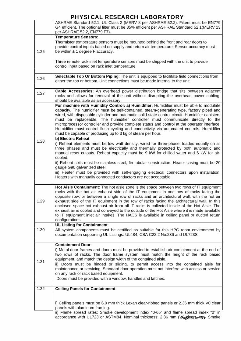
PHYSICAL RESEARCH LABORATORY
Page 51 of 53
ASHRAE Standard 52.1, UL Class 2 (MERV 8 per ASHRAE 52.2). Filters must be EN779 G4 efficient. The optional filter must be 85% efficient per ASHRAE Standard 52.1(MERV 13 per ASHRAE 52.2, EN779 F7). Temperature Sensors: Thermistor temperature sensors must be mounted behind the front and rear doors to provide control inputs based on supply and return air temperature. Sensor accuracy must be within ± 1 degree F accuracy. Three remote rack inlet temperature sensors must be shipped with the unit to provide control input based on rack inlet temperature.
1.25
Selectable Top Or Bottom Piping: The unit is equipped to facilitate field connections from either the top or bottom. Unit connections must be made internal to the unit.
1.26
1.27
Cable Accessories: An overhead power distribution bridge that sits between adjacent racks and allows for removal of the unit without disrupting the overhead power cabling, should be available as an accessory. For machine with Humidity Control: a) Humidifier: Humidifier must be able to modulate capacity. The humidifier must be self-contained, steam-generating type, factory piped and wired, with disposable cylinder and automatic solid-state control circuit. Humidifier canisters must be replaceable. The humidifier controller must communicate directly to the microprocessor controller and provide complete status and control at the operator interface. Humidifier must control flush cycling and conductivity via automated controls. Humidifier must be capable of producing up to 3 kg of steam per hour. b) Electric Reheat i) Reheat elements must be low watt density, wired for three-phase, loaded equally on all three phases and must be electrically and thermally protected by both automatic and manual reset cutouts. Reheat capacity must be 9 kW for chilled water and 6 kW for air-cooled. ii) Reheat coils must be stainless steel, fin tubular construction. Heater casing must be 20 gauge G90 galvanized steel. iii) Heater must be provided with self-engaging electrical connectors upon installation. Heaters with manually connected conductors are not acceptable.
1.28
1.29
Hot Aisle Containment: The hot aisle zone is the space between two rows of IT equipment racks with the hot air exhaust side of the IT equipment in one row of racks facing the opposite row; or between a single row of racks and an architectural wall, with the hot air exhaust side of the IT equipment in the row of racks facing the architectural wall. In this enclosed space hot exhaust air from all IT racks is collected inside of the Hot Aisle. The exhaust air is cooled and conveyed to the outside of the Hot Aisle where it is made available to IT equipment inlet air intakes. The HACS is available in ceiling panel or ducted return configurations UL Listing for Containment: All system components must be certified as suitable for this HPC room environment by documentation supporting UL Listings: UL484, CSA C22.2 No.236 and UL723S.
1.30
Containment Door: i) Metal door frames and doors must be provided to establish air containment at the end of two rows of racks. The door frame system must match the height of the rack based equipment, and match the design width of the contained aisle. ii) Doors must be hinged or sliding, to permit access into the contained aisle for maintenance or servicing. Standard door operation must not interfere with access or service on any rack or rack based equipment. Doors must be provided with a window, handles and latches.
1.31
Ceiling Panels for Containment: 1.32
i) Ceiling panels must be 6.0 mm thick Lexan clear-ribbed panels or 2.36 mm thick V0 clear panels with aluminum framing. ii) Flame spread rates: Smoke development index "0-65" and flame spread index “0” in accordance with UL723 or ASTM84. Nominal thickness: 2.36 mm (V0 clear) –or-- Smoke

PHYSICAL RESEARCH LABORATORY
Page 52 of 53
development index "20" and flame spread index "0" in accordance with UL723 or ASTM84. Nominal thickness: 6.0 mm (Lexan) .Minimum Light Transmission per ASTM D1003 equal to 82% or greater.

PHYSICAL RESEARCH LABORATORY
Page 53 of 53
Annexure VI: HPC Racks and Rack PDUs
Ser No
Technical Specifications Required
1.1 HPC Server Racks Minimum Qty 7 no.
1.2 42U Server racks
1.3 Maximum Height of the rack along with Casters mustn't be more than 1995 mm
1.4 Minimum Width of the rack must be 600mm
1.5 Depth of the rack must be at least 1070mm or more
1.6 Weight Carrying Capacity (static load) must be more than 1360 kg and (dynamic load) must be more than 1020 kg
1.7 Rack Hardware mounting Frame Width 19"
1.8 Color must be Black
1.9 Front door must be perforated single and rear doors must be perforated split doors
1.10 Guage Ratings of rack material is as below: Vertical Posts - 16 gauge Front Door - 16 gauge Rear Door - 18 gauge Roof - 18 gauge EIA Mounting Rails - 14 gauge Side Panels – 18 gauge
1.11 Weight of the rack 125Kg or more
1.12 Side Panel with single point locking with quick release latches
1.13 Rack must have Regulatory Approvals/Standards: - UL 60950-1 , EIA-310-E
1.14 Perforation pattern for Front door must be 66% and for rear doors it must be 74% at least
1.15 Rack must include - Vertical Cable managers on both the sides, Earth Kit, Casters andLevelers, Mounting Hardware, Baying Hardware kit
1.16 Rack must have Cable access openings with pre-installed brushes in the roof
1.17 Rack must be factory fitted and completely assembled rack must come to site
1.18 Rack must have one temperature and humidity sensor per rack
1.19 There must be lock and key facility for both - front and back doors and side panels
1.20 Rack must have cable entry opening in the roof of the rack as also from the bottom along with the brush strips. Cable entry cut must be both on the left and right hand side.
1.21 Rack must have cable routing accessories on top of the rack for Data and Power cables
1.22 Standard Warranty on Rack must be minimum 5 years repair or replace
1.23 Metered IP RACK PDUs : Qty 2 per Rack a) 22KW three phase Metered, zero U PDU, with at least IEC 320 C13 (5 amps) 30
sockets and C19 (15 amps) 12 sockets and at least 1.83 Meter input chord with IEC 309 industrial socket
b) PDU must be metered which includes real power monitoring temperature humidity sensor port and must have accessibility through secure web, SNMP, or telnet interface, locking IEC receptacles, and ultra low profile circuit breakers
c) PDU must have USB Port for firmware upgrade and LCD Screen 1.24 Power Cables: 48 nos. of Factory integrated Power cords (Left and Right equally
distributed,90 degree C13 to C14, 1.8m with locking) per Rack