Embed Size (px)
Citation preview

2000-02-25 IEEE 802.16.1pc-00/13
0
Project IEEE 802.16 Broadband Wireless Access Working Group
Title Physical Layer Proposal for the 802.16 Air Interface Specification
DateSubmitted
2000-02-25
Source Jeff FoersterNewbridge Networks
Co-contributorsArun V. Arunachalam and George StamatelosFarid Elwailly and Jung YeePhil GuillemetteMoshe RanWayne Hunter and Leland LangstonWilliam Myers and Scott MarinGeorge FishelRay W. SandersKarl Stambaugh and Glen SaterChet Shirali
Voice: 408-745-3983Fax: 408-745-2506mailto:[email protected] NetworksNewbridge NetworksSpaceBridge Networks CorporationTelesciCOMRaytheon Telecommunications CompanySpectrapoint Wireless, LLCCommunications Consulting ServicesCircuitPath Network SystemsMotorolaVyyo Inc.
Re: This contribution is a response to the invitation to provide a detailed proposal for a physical layerspecification, based upon the acceptance of the proposal presented at Session #5.
Abstract This contribution provides a detailed description of a physical layer that incorporates manyaspects of existing standards in order to leverage existing technology, with modifications toensure reliable operation in the targeted 10-60 GHz frequency band. In addition, it was designedwith a high degree of flexibility in order to optimize system deployments with respect to cellplanning, cost considerations, radio capabilities, offered services, and capacity requirements.
Purpose To provide a detailed description of a proposed physical layer specification for IEEE 802.16 WG.
Notice This document has been prepared to assist IEEE 802.16. It is offered as a basis for discussion andis not binding on the contributing individual(s) or organization(s). The material in this documentis subject to change in form and content after further study. The contributor(s) reserve(s) the rightto add, amend or withdraw material contained herein.
Release The contributor acknowledges and accepts that this contribution may be made public by 802.16.
IEEEPatentPolicy
The contributor is familiar with the IEEE Patent Policy, which is set forth in the IEEE-SAStandards Board Bylaws <http://ieee802.org/16/ipr/patents/bylaws.html> and includes thestatement:
“IEEE standards may include the known use of patent(s), including patent applications, if there istechnical justification in the opinion of the standards-developing committee and provided theIEEE receives assurance from the patent holder that it will license applicants under reasonableterms and conditions for the purpose of implementing the standard.”

2000-02-25 IEEE 802.16.1pc-00/13
1
See <http://ieee802.org/16/ipr> for details.
2000-02-25 IEEE 802.16.1pc-00/13
2
Physical Layer Proposal for the 802.16 Air Interface SpecificationTABLE OF CONTENTS
1 SCOPE......................................................................................................................................................................................4
2 NORMATIVE REFERENCES................................................................................................................................................5
3 PHYSICAL LAYER OVERVIEW..........................................................................................................................................6
3.1 INTRODUCTION ...................................................................................................................................................................63.2 REFERENCE CONFIGURATION...............................................................................................................................................63.3 MULTIPLEXING AND MULTIPLE ACCESS TECHNIQUE ............................................................................................................73.4 DUPLEXING TECHNIQUE ......................................................................................................................................................73.5 BAUD RATES AND CHANNEL BANDWIDTHS ..........................................................................................................................83.6 DOWNSTREAM CODING, INTERLEAVING, SCRAMBLING & MODULATION...............................................................................83.7 UPSTREAM CODING, INTERLEAVING, SCRAMBLING & MODULATION ....................................................................................8
4 DOWNSTREAM PHYSICAL LAYER...................................................................................................................................9
4.1 DOWNSTREAM TRANSMISSION CONVERGENCE (TC) SUBLAYER ...........................................................................................94.2 PHYSICAL MEDIA DEPENDENT (PMD) SUBLAYER ..............................................................................................................12
4.2.1 Baseband interfacing ................................................................................................................................................124.2.2 Sync byte inversion and randomization......................................................................................................................124.2.3 Reed-Solomon coding................................................................................................................................................144.2.4 Convolutional interleaving ........................................................................................................................................154.2.5 Convolutional Coding with QPSK Modulation...........................................................................................................154.2.6 Convolutional Coding with 8-PSK Modulation (optional) ..........................................................................................164.2.7 Convolutional Coding with 16-QAM Modulation (optional).......................................................................................164.2.8 Differential encoding with QPSK or 16-QAM Modulation (16-QAM is optional)........................................................164.2.9 Differential encoding with 64-QAM Modulation (optional) ........................................................................................184.2.10 Baseband Pulse Shaping ...........................................................................................................................................194.2.11 Summary of Downstream Physical Layer Parameters ................................................................................................19
5 UPSTREAM PHYSICAL MEDIA DEPENDENT (PMD) SUBLAYER ..............................................................................20
5.1 PHYSICAL MEDIA DEPENDENT (PMD) SUBLAYER ..............................................................................................................205.1.1 Reed-Solomon coding................................................................................................................................................205.1.2 Preamble ..................................................................................................................................................................215.1.3 Randomization for spectrum shaping.........................................................................................................................215.1.4 Modulation ...............................................................................................................................................................21
5.1.4.1 QPSK Symbol Mapping .......................................................................................................................................................... 215.1.4.2 Differentially encoded 16-QAM (optional)............................................................................................................................... 215.1.4.3 Gray-coded 16-QAM (optional)............................................................................................................................................... 22
5.1.5 Baseband Pulse Shaping ...........................................................................................................................................235.1.6 Summary of Upstream Physical Layer Parameters ....................................................................................................23
5.2 UPSTREAM CHANNEL DESCRIPTION ....................................................................................................................................245.3 BURST PROFILES................................................................................................................................................................24
6 RADIO SUB-SYSTEM CONTROL ......................................................................................................................................25
6.1 SYNCHRONIZATION TECHNIQUE (FRAME AND SLOT) ..........................................................................................................256.2 FREQUENCY CONTROL ......................................................................................................................................................256.3 POWER CONTROL ..............................................................................................................................................................25
7 PHYSICAL LAYER TRANSMITTER CHARACTERISTICS ...........................................................................................26
8 EVALUATION TABLE.........................................................................................................................................................28
8.1 REFERENCE SYSTEM GAIN.................................................................................................................................................29
LIST OF FIGURESFigure 1: Reference Configuration .....................................................................................................................................................7

2000-02-25 IEEE 802.16.1pc-00/13
3
Figure 2: Format of an MPEG Packet.................................................................................................................................................9Figure 3: Packet Format Where a MAC Frame Immediately Follows the pointer_field......................................................................10Figure 4: Packet Format with MAC Frame Preceded by Stuffing Bytes.............................................................................................11Figure 5: Packet Format Showing Multiple MAC Frames in a Single Packet.....................................................................................11Figure 6: Packet Format Where a MAC Frame Spans Multiple Packets.............................................................................................11Figure 7: Conceptual Block diagram of the 802.16 Continuous Transmission Downstream Physical Layer........................................12Figure 8: Randomizer logic diagram.................................................................................................................................................13Figure 9: Framing structure based on MPEG transport stream...........................................................................................................14Figure 10: Conceptual diagram of the convolutional interleaver and de-interleaver. ..........................................................................15Figure 11: QPSK symbol mapping ...................................................................................................................................................16Figure 12: Example implementation of the byte to m-tuple conversion and the differential encoding of the two MSBs. ....................17Figure 13: 16 QAM Constellation diagram.......................................................................................................................................18Figure 14: 64-QAM Constellation Diagram......................................................................................................................................18Figure 15: Conceptual Block diagram of the 802.16 Burst Transmission Upstream Physical Layer....................................................20Figure 16: QPSK constellation mapping...........................................................................................................................................21Figure 17: Differentially encoded 16-QAM Constellation diagram....................................................................................................22Figure 18: Gray-coded 16-QAM Constellation diagram....................................................................................................................23
2000-02-25 IEEE 802.16.1pc-00/13
4
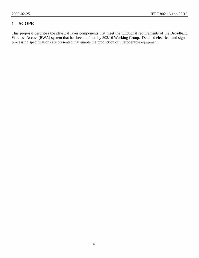
1 SCOPE
This proposal describes the physical layer components that meet the functional requirements of the BroadbandWireless Access (BWA) system that has been defined by 802.16 Working Group. Detailed electrical and signalprocessing specifications are presented that enable the production of interoperable equipment.

2000-02-25 IEEE 802.16.1pc-00/13
5
2 NORMATIVE REFERENCES[1] ETSI EN 300 421 V1.1.2 (1997-08), "Digital Video Broadcasting (DVB); Framing structure, channelcoding and modulation for 11/112 GHz satellite services."
[2] ETSI EN 301 210 V1.1.1 (1999-03), "Digital Video Broadcasting (DVB); Framing structure, channelcoding and modulation for Digital Satellite News Gathering (DSNG) and other contribution applications bysatellite."
[3] ITU-T J.83 (04/97), Series J: Transmission of Television, Sound Programme and Other Multimedia Signals:Digital transmission of television signals, "Digital multi-programme systems for television, sound and dataservices for cable distribution."
[4] Data-Over-Cable Service Interface Specifications, "Radio Frequency Interface Specification," SP-RFIv1.1-I03-991103.
[5] ETSI EN 301 199 v1.2.1 (1999-06), "Digital Video Broadcasting (DBV); Interaction channel for LocalMulti-point Distribution Systems (LMDS)."
[6] ITU-T draft Recommendation J.116, "Interaction channel for Local Multipoint Distribution services."
[7] ITU-R 9B/134-E, JRG 8A-9B, Draft New Recommendation ITU-R F.BWA, "Radio Transmission Systemsfor Fixed Broadband Wireless Access (BWA) Based on Cable Modem Standards (Annex B of ITU-T Rec.J.112)."

2000-02-25 IEEE 802.16.1pc-00/13
6
3 PHYSICAL LAYER OVERVIEW
3.1 INTRODUCTION
The following physical layer specification was designed to meet the functional requirements that have beendefined for Broadband Wireless Access (BWA) systems. It incorporates many aspects of existing standards [1]-[7] in order to leverage existing technology for reduced equipment cost and demonstrated robustness ofimplementation, with modifications to ensure reliable operation in the targeted 10-60 GHz frequency band. Inaddition, this physical layer was designed with a high degree of flexibility in order to allow service providersthe ability to optimize system deployments with respect to cell planning, cost considerations, radio capabilities,offered services, and capacity requirements. This proposed physical layer has been optimally designed tosupport a continuous transmission in the downstream channel and a burst transmission in the upstream channel,which is expected to meet the majority of BWA system requirements today and in the future. It should be notedthat this proposal does not limit the possible future adoption of a complementary physical layer specificationsupporting burst transmission in the downstream by sharing many of the same elements present in this proposedphysical layer specification.
Several optional implementations have been identified in this proposal in order to allow vendors the ability toadd additional flexibility to both the upstream and downstream physical layers as needed. It is mandatory thatan 802.16 standards compliant subscriber station support the basic physical layer components described here,while the elements that are identified as "optional" need not be implemented in order to be standards compliant.If the options are implemented, they shall be implemented as described here. This approach to the physicallayer specification allows for rapid time to market for this standard, using existing and mature technology, whileproviding a migration path for more advanced coding and modulation schemes supporting different services,higher capacity links, and/or lower equipment cost following the market demands.
3.2 REFERENCE CONFIGURATION
The physical layer is designed to support both 802.16 MAC frames and native MPEG packets in thedownstream channel. However, all traffic must still pass through the MAC for scheduling of the availablebandwidth for both the upstream and downstream channels. The support of native MPEG video packets hasbeen incorporated into the physical layer, so that they do not need to be encapsulated into 802.16 MAC framesfor seamless integration into a video distribution network. Below is a simple reference model that is used toshow the interface between the physical layer and the MAC layer, and to show how the MAC layer mightinterface with higher layers. The convergence layer between the MAC and higher layers is beyond the scope ofthis specification, but the convergence layer between the MAC and PHY is clearly defined in the followingsections in order to ensure interoperation between the two entities.

2000-02-25 IEEE 802.16.1pc-00/13
7
IP T1 POTS
Convergence Layer
MAC
Convergence Layer Convergence Layer
MAC
Convergence Layer
Wireless link
PHY PHY
MPEG
Figure 1: Reference Configuration
3.3 MULTIPLEXING AND MULTIPLE ACCESS TECHNIQUE
The upstream physical layer is based on the use of a combination of time division multiple access (TDMA) anddemand assigned multiple access (DAMA). In particular, the upstream channel is divided into a number of"time slots". The number of slots assigned for various uses (polling, contention, guard, or reserved) iscontrolled by the MAC layer in the basestation and can vary in time for optimal performance. The downstreamchannel is based upon time division multiplexing (TDM), where the information for each subscriber station ismultiplexed onto the same stream of data and is received by all subscriber stations located within the samesector.
3.4 DUPLEXING TECHNIQUE
This physical layer has been targeted to support frequency division duplexing (FDD), which provides a separatefrequency assignment for the upstream and downstream channels. This approach to transmitter and receiverisolation is a proven technique that has been utilized by many other wireless systems, including cellular, PCS,and satellite communication systems. In addition, it allows for low cost modem receivers to be used in thesubscriber station units that have been designed to demodulate signals with continuous transmission. There alsoexists several techniques, including the use of ortho-mode transducers (OMTs), which enables radio equipmentto be designed to meet a wide variety of channelization plans as well as to meet various cost targets.
This proposal does not prevent the adoption of a separate, complementary physical layer specification that isbetter suited for burst transmission in the downstream channel in order to support time division duplexing(TDD). Due to interference considerations, it is not expected that frequency division duplexed and timedivision duplexed systems will coexist in the same geographical areas. In addition, continuous transmissionsystems and burst transmission systems have different design constraints and would be better served throughdifferent specifications. Thus, it is recommended that separate physical layers be adopted by the 802.16

2000-02-25 IEEE 802.16.1pc-00/13
8
working group in order to address the different requirements for continuous and burst transmission in thedownstream channel. Maximizing the commonality between the two physical layer specifications will allow forcost effective silicon solutions in the future that can support both modes of operation.
3.5 BAUD RATES AND CHANNEL BANDWIDTHS
Due to the large amount of spectrum available in the 10-60 GHz region for point-to-multipoint operation, andthe different regulatory requirements in various countries around the world, the baud rates and RF channelbandwidths should be left very flexible in order to allow service providers the ability to maximize capacity for agiven spectrum allocation. Subscriber station equipment should support symbol rates that lie in the interval 10Mbaud to 40 Mbaud for the downstream continuous mode transmission and 5 Mbaud to 30 Mbaud for burstmode transmissions. The granularity of the baud rates and/or channel sizes, and specific recommendations forinteroperability testing is TBD.
3.6 DOWNSTREAM CODING, INTERLEAVING, SCRAMBLING & MODULATION
The downstream physical layer has been designed for a continuous transmission stream with added flexibility toenable system wide optimization for various deployment scenarios. First, MAC packets are encapsulated intoan MPEG frame as defined by the transmission convergence sublayer, and then the data is randomized andencoded using a (204,188) Reed-Solomon code over GF(256). Following the outer block encoder, the data goesthrough a convolutional interleaver with a depth of I=12. Then, the data must either pass through an inner,constraint length K=7, convolutional code with a rate of ½, 2/3, ¾, 5/6, or 7/8, or pass through a differentialencoder (i.e., bypassing the convolutional encoder) as defined in the following sections. In order to ensureinteroperability in different system configurations, a subscriber station must support both data paths. Code bitsare then mapped to a QPSK, 8-PSK (optional), 16-QAM (optional), or 64-QAM (optional) signal constellationwith symbol mapping as described here. Finally, symbols are Nyquist filtered using a square-root raised cosinefilter with a roll-off factor of either 0.15 or 0.35.
3.7 UPSTREAM CODING, INTERLEAVING, SCRAMBLING & MODULATION
The upstream physical layer has been designed to support burst modulation for a TDMA based system. Sincemany of the specific upstream channel parameters can be programmed by MAC layer messaging coming fromthe basestation, several parameters can be left unspecified and configured by the basestation in order tooptimize performance for a particular deployment scenario. In this mode, each burst is designed to carry MACmessages of variable lengths, and first encodes the incoming MAC messages using a Reed-Solomon encoderbased on GF(256), and then randomizes the complete outgoing burst. The length of the codeword and the errorcorrection capability of the code are programmable by the MAC messages coming from the basestation via aburst configuration message. Each burst also contains a variable length preamble and a variable length guardspace at the end of the burst. The preamble and coded bits are mapped to QPSK or 16-QAM (optional)constellations. Nyquist pulse shaping using a square-root raised cosine filter is also employed with a roll-offfactor of either 0.15, 0.25, or 0.35.

2000-02-25 IEEE 802.16.1pc-00/13
9
4 DOWNSTREAM PHYSICAL LAYER
4.1 DOWNSTREAM TRANSMISSION CONVERGENCE (TC) SUBLAYERIn order to improve demodulation robustness, facilitate common receiving hardware for both video and data,and provide an opportunity for the possible multiplexing of video and data over the physical layer, the followingconvergence sublayer between the MAC and PHY layer has been adopted.
The downstream bitstream is defined as a continuous series of 188-byte MPEG [ITU-T H.222.0] packets.These packets consist of a 4-byte header followed by 184 bytes of payload. The header identifies the payload ascontaining 802.16 MAC messages or other types of payloads, including digital video. The mixtures of thevarious services that are transported in the downstream are to be controlled by the basestation.
The format of the MPEG Packet carrying MAC messages is given below
Figure 2: Format of an MPEG Packet
The format of the MPEG transport stream header is defined in Section 2.4 of [ITU-T H.222.0]. The particularfield values that distinguish the 802.16 MAC message stream are defined in the following table, where the fieldnames are from the ITU specification. The MPEG header consists of 4 bytes that begin the 188-byte MPEGpacket. The format of the header for use on an 802.16 PID is restricted to that shown in the table. The headerformat conforms to the MPEG standard, but its use is restricted in this specification to NOT ALLOW inclusionof an adaptation_field in the MPEG packets.
Table 1: MPEG Header Format for 802.16 MAC packets
Field Length(bits)
Description
sync_byte 8 0x47 or 0xB8; MPEG Packet sync byte
transport_error_indicator 1 Indicates an error has occurred in the reception of thepacket. This bit is reset to zero by the sender, and set toone whenever an error occurs in the transmission of thepacket.
payload_unit_start_indicator(PUSI)
1 A value of one indicates the presence of a pointer_field asthe first byte of the payload (fifth byte of the packet).
transport_priority(frame_start_indicator)
1 This bit is set to 1 to indicate the beginning of adownstream frame, when framing is used.
PID 13 802.16 well-known packet ID (TBD)
transport_scrambling_control 2 Reserved, set to '00'
adaptation_field_control 2 '01'; use of the adaptation_field is NOT ALLOWED onthe 802.16 PID
Header4 bytes
PayloadP
P=1 byte pointer field, not present in all packets

2000-02-25 IEEE 802.16.1pc-00/13
10
continuity_counter 4 cyclic counter within this PID
The payload portion of the MPEG packet will carry the 802.16 MAC frames. The first byte of the MPEGpayload will be a 'pointer_field' if the PUSI is set. A stuff_byte pattern having a value (0xFF) must be usedwithin the MPEG payload to fill any gaps between the 802.16 MAC frames. This value is chosen as an unusedvalue for the first byte of the 802.16 MAC frame, which is designed to NEVER have this value. Thepointer_field is present as the fifth byte of the MPEG packet (first byte following the MPEG header) wheneverthe PUSI is set to one in the MPEG header. The interpretation of the pointer_field is as follows:
The pointer_field contains the number of bytes in the packet that immediately follow the pointer_field that thesubscriber station decoder must skip past before looking for the beginning of an 802.16 MAC frame. A pointerfield MUST be present if it is possible to begin an 802.16 MAC frame in the packet, and MUST point to either:
1. the beginning of the first MAC frame to start in the packet or
2. to any stuff_byte preceding the MAC frame.
MAC frames may begin anywhere within an MPEG packet, MAC frames may span MPEG packets, and severalMAC frames may exist within an MPEG packet. The following figures show the format of the MPEG packetsthat carry 802.16 MAC frames. In all cases, the PUSI flag indicates the presence of the pointer_field as the firstbyte of the MPEG payload. The following figure shows a MAC frame that is positioned immediately after thepointer_field byte. In this case, pointer_field is zero, and the 802.16 decoder will begin searching for a validMAC header byte at the byte immediately following the pointer_field.
Figure 3: Packet Format Where a MAC Frame Immediately Follows the pointer_field
The next figure shows the more general case where a MAC Frame is preceded by the tail of a previous MACFrame and a sequence of stuffing bytes. In this case, the pointer_field still identifies the first byte after the tail ofFrame #1 (a stuff_byte) as the position where the decoder should begin searching for a legal MAC header byte.This format allows the multiplexing operation in the basestation to immediately insert a MAC frame that isavailable for transmission if that frame arrives after the MPEG header and pointer_field has been transmitted.
In order to facilitate multiplexing of the MPEG packet stream carrying 802.16 data with other MPEG-encodeddata, the basestation SHOULD NOT transmit MPEG packets with the 802.16 PID which contain onlystuff_bytes in the payload area. MPEG null packets SHOULD be transmitted instead. Note that there are timingrelationships implicit in the 802.16 MAC sublayer which must also be preserved by any MPEG multiplexingoperation.
Header(PUSI=1)
MAC frame(up to 183 bytes)
P=0
P=1 byte pointer field
stuff_byte(0 or more)

2000-02-25 IEEE 802.16.1pc-00/13
11
Figure 4: Packet Format with MAC Frame Preceded by Stuffing Bytes
The next figure shows that multiple MAC frames may be contained within the MPEG packet. The MAC framesmay be concatenated one after the other or be separated by an optional sequence of stuffing bytes.
Figure 5: Packet Format Showing Multiple MAC Frames in a Single Packet
The next figure shows the case where a MAC frame spans multiple MPEG packets. In this case, thepointer_field of the succeeding frame points to the byte following the last byte of the tail of the first frame.
Figure 6: Packet Format Where a MAC Frame Spans Multiple Packets
Header(PUSI=1)
Tail of MAC frame #1(M bytes)
P=M
P=1 byte pointer field
stuff_byte(0 or more)
Start of MACFrame 2
Header(PUSI=1)
MAC Frame1
P=0
P=1 byte pointer field
stuff_byte(0 or more)
Start of MACFrame 3
MAC Frame2
Header(PUSI=1)
P=0
P=1 byte pointer field
stuff_byte(0 or more)
Start of MAC Frame 1(up to 183 bytes)
Header(PUSI=0)
P=0
Continuation of MAC frame 1(184 bytes)
Header(PUSI=1)
Tail of MAC frame 1(M bytes)
P=M
stuff_byte(0 or more)
Start of MACFrame 2

2000-02-25 IEEE 802.16.1pc-00/13
12
4.2 PHYSICAL MEDIA DEPENDENT (PMD) SUBLAYERThe encoding and decoding functions for the downstream physical layer are summarized in the following blockdiagram.
Figure 7: Conceptual Block diagram of the 802.16 Continuous Transmission Downstream Physical Layer
4.2.1 Baseband interfacing
This unit shall perform the transmission convergence sublayer function by adapting the data structure comingfrom the MAC layer to the format of the proposed physical layer transport stream based on the MPEG packetstructure.
4.2.2 Sync byte inversion and randomization
This unit shall invert the Sync byte according to the MPEG framing structure, and randomizes the data streamfor spectrum shaping purposes. Randomization shall be employed to minimize the possibility of transmissionof an unmodulated carrier and to ensure adequate numbers of bit transitions to support clock recovery.
The stream of uncoded downstream packets, excluding sync bytes, shall be randomized by modulo-2 additionof the data with the output of the pseudo random binary stream (PBRS) generator, as illustrated in the followingdiagram.
Base-band
Interface
Syncbyte
inversion&
Randomization
Reed-Solomon
Coder(204,188)
Convol.Interleaver
Convol.Code
Puncturing/Mapping
BasebandPulse
Shaping
Modulatorand
PhysicalInterface
Data
Base station
To RFChannel
PhysicalInterfaceDemod.
MatchedFilter
&Equalizer
Depunc./Convol.decoder
Convol.de-
interleaver
Reed-SolomonDecoder
Synch1byte
inversion &derandomi
zation
Basebandinterface
Subscriber station
FromRF Channel
Data

2000-02-25 IEEE 802.16.1pc-00/13
13
10 11 12 13 14 151 2 3 4 5 6 7 8 9
1 0 0 0 0 0 0 0 0 0 0 01 1 1
initialization sequence
EX-OR
EX-ORRandomized/clear
data outputClear/randomizeddata input
AND
Enable
00000011 ....
Data input (MSB first):PRBS sequence:
1 0 1|1 1 0 0 0 x x x|x x x x x .... | | 0 0 0|0 0 0 1 1 .... |
Figure 8: Randomizer logic diagram.
The PBRS shall be initialized at each inverted sync byte by the sequence 100101010000000 in the mannerdepicted in the figure. The sync byte (hex 47) shall be inverted (hex B8) every eight packets, starting at thebeginning of the frame.
The generator polynomial for the PRBS shall be:
1 + X14 + X15
Following initialization, the first PRBS generator output bit shall be added to the first bit following the invertedsync bit. Over subsequent sync bytes, the PBRS generator shall continue to step its internal shift register statebut the PBRS output addition to the sync byte bits shall be disabled. Thus, the period of the PRBS sequenceshall be 1504 bytes. The following diagram illustrates the framing structure of the MPEG transport stream.

2000-02-25 IEEE 802.16.1pc-00/13
14
Figure 9: Framing structure based on MPEG transport stream.
4.2.3 Reed-Solomon coding
Following the energy dispersal randomization process, systematic shortened Reed-Solomon encoding shall beperformed on each randomized MPEG transport packet, with T = 8. This means that 8 erroneous bytes pertransport packet can be corrected. This process adds 16 parity bytes to the MPEG transport packet to give acodeword (204,188). RS coding shall also be applied to the packet sync byte, either non-inverted (i.e. 47hex) orinverted (i.e. B8hex).
The Reed-Solomon code shall have the following generator polynomials:
Code Generator Polynomial: g(x) = (x+µ0)(x+µ1)(x+µ2) ... (x+µ15), where µ= 02hex
Field Generator Polynomial: p(x) = x8 + x4 + x3 + x2 + 1
The shortened Reed-Solomon code shall be implemented by appending 51 bytes, all set to zero, before theinformation bytes at the input of a (255,239) encoder; after the coding procedure these bytes are discarded.
Sync.byte
187 bytes
(a) MPEG Transport Stream MUX Packet
Sync1R
187 bytesSync2
R187 bytes
Sync8R
187 bytesSync1
R187 bytes
(b) Randomized transport packets: Sync bytes and Raondomized Sequence R
Sync.byte
187 bytes RS(204,188)
PRBS period = 1504 bytes
(c) Reed-Solomon RS(204,188,t=8) error protected packet
204 bytes
Syncbytes
203 bytesSyncbyte
203 bytes
(d) Interleaved Frames maintaining sync. byte periodicity
Sync1 = not randomized complemented sync byte
Sync n = not randomized sync byte, n=2...8

2000-02-25 IEEE 802.16.1pc-00/13
15
4.2.4 Convolutional interleaving
The convolutional interleaving process shall be based on the Forney approach, with a depth of I=12. Theinterleaved frame shall be composed of overlapping error protected packets and shall be delimited by MPEGsync bytes (preserving the periodicity of 204 bytes).
The interleaver is composed of I branches, cyclically connected to the input byte-stream by the input switch.Each branch shall be a First In First Out (FIFO) shift register, with depth (M) cells (where M = N/I,N = 204 = error protected frame length, I =12 = maximum interleaving depth, j = branch index). The cells of theFIFO shall contain 1 byte, and the input and output switches shall be synchronized, as shown in the diagrambelow.
For synchronization purposes, the sync bytes and the inverted sync bytes shall be always routed into the branch"0" of the interleaver (corresponding to a null delay).
The deinterleaver is similar, in principle, to the interleaver, but the branch indexes are reversed (i.e. j = 0corresponds to the largest delay). The de-interleaver synchronization is achieved by routing the first recognizedsync byte into the "0" branch.
Figure 10: Conceptual diagram of the convolutional interleaver and de-interleaver.
4.2.5 Convolutional Coding with QPSK Modulation
When convolutional encoding is employed, the convolutional code shall be chosen from the following table ofcode rates, which are obtained by puncturing a rate 1/2 constraint length K = 7 code having the followinggenerator vectors g, and puncturing patterns P (0 denotes punctured (deleted) bit).
M
M M
M M M
M M M M
M
M M
M M M
M M M M0
1
2
3
I-1
0
1
2
3
I-1
0
I-4
I-3
I-2
I-1
0
I-4
I-3
I-2
I-1
1 byte perposition
Channel
Convolutional Interleaver Convolutional De-interleaver
M M-stage FIFO shift register
sync word routesync word route

2000-02-25 IEEE 802.16.1pc-00/13
16
Table 2: Convolutional Code Puncture Patterns
Original code Code rates
1/2 2/3 3/4 5/6 7/8
K G1 G2 P dfree P dfree P dfree P dfree P dfree
7 171oct 133oct
X=1
Y=1
I=X1
Q=Y1
10
X=10
Y=11
I=X1Y2Y3
Q=Y1X3Y4
6
X=101
Y=110
I=X1Y2
Q=Y1X3
5
X=10101
Y=11010
I=X1Y2Y4
Q=Y1X3X5
4
X=1000101
Y=1111010
I=X1Y2Y4Y6
Q=Y1Y3X5X7
3
NOTE: 1=transmitted bit0 = non transmitted bit
The QPSK symbols will use gray-coded direct mapping of (I,Q) from bit pairs out of the convolutional encoderas follows:
0010
0111
Figure 11: QPSK symbol mapping
4.2.6 Convolutional Coding with 8-PSK Modulation (optional)
8-PSK shall be optionally supported using a rate 2/3, 5/6, or 8/9 punctured convolutional code as describedabove with the inner coding and constellation mapping as described in [2].
4.2.7 Convolutional Coding with 16-QAM Modulation (optional)
16-QAM shall be supported using a rate ¾ or 7/8 punctured convolutional code as described above with theinner coding and constellation mapping as described in [2].
4.2.8 Differential encoding with QPSK or 16-QAM Modulation (16-QAM is optional)
In this mode, the inner convolutional code is disabled, and the mapping of bits to symbols shall use thefollowing differential encoder and mapper as defined in [3, ITU-T J.83 Annex A]. The two most significantbits (MSBs) of each symbol shall be differentially coded in order to obtain a π/2 rotation-invariant QAMconstellation. The differential encoding of the two MSBs shall be given by the following Boolean expression:

2000-02-25 IEEE 802.16.1pc-00/13
17
( ) ( ) ( ) ( )
( ) ( ) ( ) ( )
I A B A I A B A Q
Q A B B Q A B B I
k k k k k k k k k
k k k k k k k k k
= ⊕ ⊕ + ⊕ ⊕
= ⊕ ⊕ + ⊕ ⊕
− −
− −
. .
. .
1 1
1 1
Note: For the above Boolean expression "⊕" denotes the EXOR function, "+" denotes the logicalOR function, "." denotes the logical AND function and the overstrike denotes inversion.
The following figure gives an example of implementation of byte to symbol conversion.
fromconvolutionalinterleaver
Byteto
m-tupleconversion I
k
Qk
bq-1
b0
Bk
= bq
Ak
= bq+1
q bits ( ... )
I and Q
mappingdifferentialencoding
I
Q
8
q=1 for QPSK, q=2 for 16-QAM
Figure 12: Example implementation of the byte to m-tuple conversionand the differential encoding of the two MSBs.
For QPSK, the output of the differential encoder shall map directly to the QPSK signal constellation based onthe Quadrant to MSB mapping shown in the following table. The mapping of bits to symbols for 16-QAM,when implemented as an option, is given by the following figure.
Table 3: Conversion of constellation of quadrant 1 to other quadrants of theconstellation diagrams given in the following diagrams.
Quadrant MSBs LSBs rotation1 00 02 10 + π/23 11 + π4 01 + 3π/2

2000-02-25 IEEE 802.16.1pc-00/13
18
I
Q10
00 01
11
I Qk k
= 00
11
10 00
01
I Qk k
= 10
01
11 10
00
I Qk k
= 11
00
01 11
10
I Qk k
= 01
Figure 13: 16 QAM Constellation diagram
4.2.9 Differential encoding with 64-QAM Modulation (optional)
The support for 64-QAM modulation shall be optionally supported in this specification in order to allow for thefuture support for higher capacity links. This option uses the same differential encoding structure describedabove, with q=4 in the differential encoder, and the following mapping of bits to symbols:
I
Q
I Qk k
= 00I Qk k
= 10
I Qk k
= 11 I Qk k
= 01
1000 1001 1101 1100
1010 1011 1111 1110
0010 0011 0111 0110
0100010100010000
0100
0101
0000
1100 1110 0110
1101 1111 0111
1001 1011 0011
001010101000
0001
0000 0010 1010
0001 0011 1011
0101 0111
1110
1111
01100100
1000
1001
1101
1100
0100 0101 0001
0110 0111 0011
1110 1111
1001
1011
11011100
0000
0010
1010
1000
Figure 14: 64-QAM Constellation Diagram
2000-02-25 IEEE 802.16.1pc-00/13
19
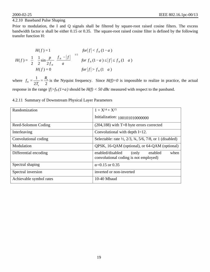
4.2.10 Baseband Pulse Shaping
Prior to modulation, the I and Q signals shall be filtered by square-root raised cosine filters. The excessbandwidth factor α shall be either 0.15 or 0.35. The square-root raised cosine filter is defined by the followingtransfer function H:
H f for f f
H ff
f ffor f f f
H f for f f
N
N
NN N
N
( ) ( )
( ) sin ( ) ( )
( ) ( )
/
= < −
= +−
− ≤ ≤ +
= > +
1 1
1
2
1
2 21 1
0 1
1 2
α
πα
α α
α
where fT
RN
s
s= =1
2 2is the Nyquist frequency. Since H(f)=0 is impossible to realize in practice, the actual
response in the range |f|>fN (1+α) should be H(f) < 50 dBc measured with respect to the passband.
4.2.11 Summary of Downstream Physical Layer Parameters
Randomization 1 + X14 + X15
Initialization: 100101010000000
Reed-Solomon Coding (204,188) with T=8 byte errors corrected
Interleaving Convolutional with depth I=12.
Convolutional coding Selectable: rate ½, 2/3, ¾, 5/6, 7/8, or 1 (disabled)
Modulation QPSK, 16-QAM (optional), or 64-QAM (optional)
Differential encoding enabled/disabled (only enabled whenconvolutional coding is not employed)
Spectral shaping α=0.15 or 0.35
Spectral inversion inverted or non-inverted
Achievable symbol rates 10-40 Mbaud
2000-02-25 IEEE 802.16.1pc-00/13
20
5 UPSTREAM PHYSICAL MEDIA DEPENDENT (PMD) SUBLAYER
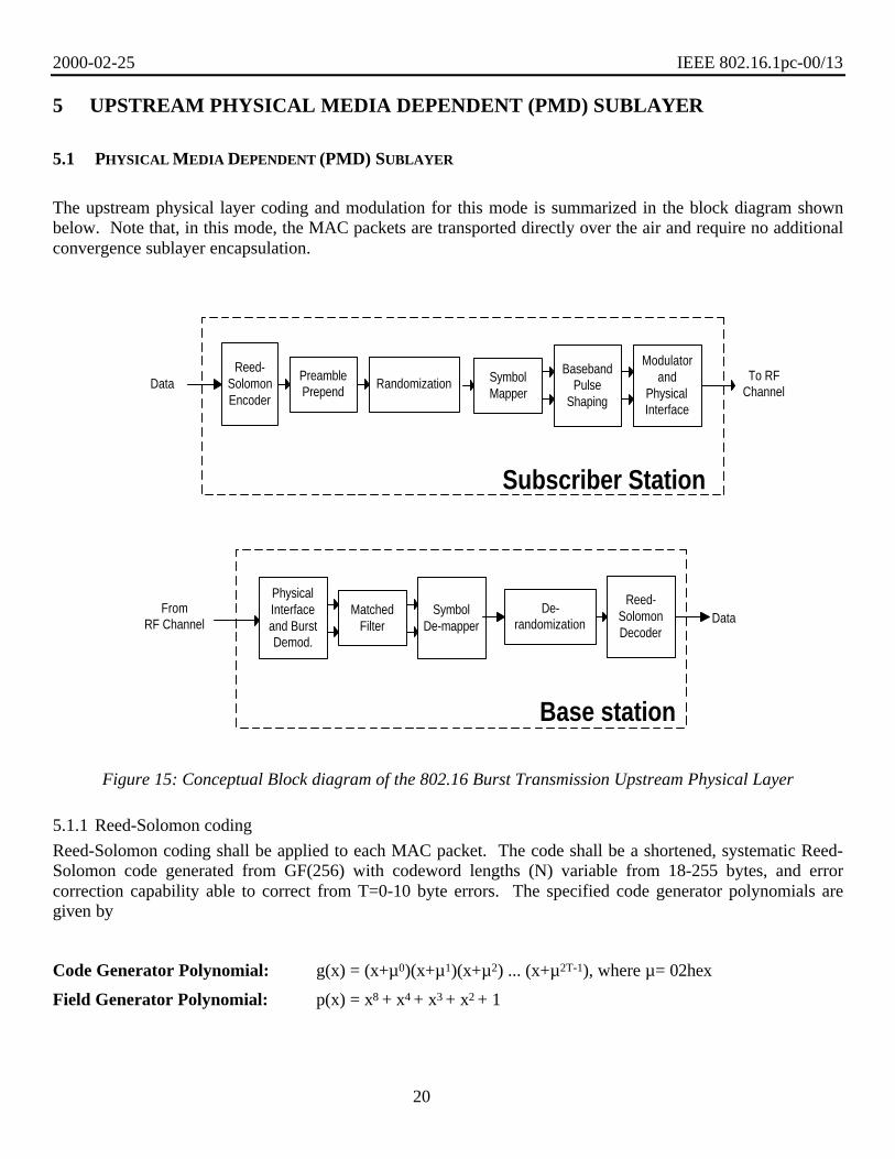
5.1 PHYSICAL MEDIA DEPENDENT (PMD) SUBLAYER
The upstream physical layer coding and modulation for this mode is summarized in the block diagram shownbelow. Note that, in this mode, the MAC packets are transported directly over the air and require no additionalconvergence sublayer encapsulation.
Figure 15: Conceptual Block diagram of the 802.16 Burst Transmission Upstream Physical Layer
5.1.1 Reed-Solomon coding
Reed-Solomon coding shall be applied to each MAC packet. The code shall be a shortened, systematic Reed-Solomon code generated from GF(256) with codeword lengths (N) variable from 18-255 bytes, and errorcorrection capability able to correct from T=0-10 byte errors. The specified code generator polynomials aregiven by
Code Generator Polynomial: g(x) = (x+µ0)(x+µ1)(x+µ2) ... (x+µ2T-1), where µ= 02hex
Field Generator Polynomial: p(x) = x8 + x4 + x3 + x2 + 1
RandomizationReed-
SolomonEncoder
PreamblePrepend
BasebandPulse
Shaping
Modulatorand
PhysicalInterface
Data
Subscriber Station
To RFChannel
FromRF Channel Data
De-randomization
SymbolDe-mapper
MatchedFilter
Reed-SolomonDecoder
PhysicalInterfaceand BurstDemod.
Base station
SymbolMapper

2000-02-25 IEEE 802.16.1pc-00/13
21
The specified code has a block length of 255 bytes, and shall be configured as a RS(255,255-2T, T) code withinformation bytes preceded by (255-N) zero symbols.
5.1.2 Preamble
The preamble should be programmable in length from 0-1024 bits and have a value that is also programmable.
5.1.3 Randomization for spectrum shaping
The upstream modulator must implement a scrambler using the polynomial x15+x14+1 with a 15-bitprogrammable seed. At the beginning of each burst, the register is cleared and the seed value is loaded. Theseed value must be used to calculate the scrambler bit, which is combined in an XOR with the first bit of data ofeach burst (which is the MSB of the first symbol following the last symbol of the preamble).
5.1.4 Modulation
The modulation used on the upstream channel should be programmable with the following options. Both QPSKand 16-QAM must be supported with the following mappings of bits to symbols.
5.1.4.1 QPSK Symbol Mapping
The following mapping of bits to symbols shall be support for QPSK modulation:
1101
1000
Figure 16: QPSK constellation mapping
If differential encoding is employed, the encoder shall accept bits A and B in sequence and generate phasechanges as follows:
A B Phase Change
0 0 none
0 1 +90 degrees
1 1 180 degrees
1 0 -90 degrees
5.1.4.2 Differentially encoded 16-QAM (optional)
If differential encoding is desired for 16-QAM, then the following signal constellation should be optionallysupported (I1 Q1 I0 Q0 represent the bits identifying the 16-QAM symbol).

2000-02-25 IEEE 802.16.1pc-00/13
22
I
Q01
00 10
11
I Qk k
= 11
11
01 00
10
I Qk k
= 01
10
11 01
00
I Qk k
= 00
00
10 11
01
I Qk k
= 10
Figure 17: Differentially encoded 16-QAM Constellation diagram
Current Input BitsI1 Q1
Quadrant Phasechange
MSBs of PreviouslyTransmitted Symbol
MSBs for CurrentlyTransmitted Symbol
00 0° 11 1100 0° 01 0100 0° 00 0000 0° 10 1001 90° 11 0101 90° 01 0001 90° 00 1001 90° 10 1111 180° 11 0011 180° 01 1011 180° 00 1111 180° 10 0110 270° 11 1010 270° 01 1110 270° 00 0110 270° 10 00
5.1.4.3 Gray-coded 16-QAM (optional)
If differential encoding is not desired, then the following signal constellation shall be optionally supported:

2000-02-25 IEEE 802.16.1pc-00/13
23
I
Q01
00 10
11
I Qk k
= 11
11
10 00
01
I Qk k
= 01
10
11 01
00
I Qk k
= 00
00
01 11
10
I Qk k
= 10
Figure 18: Gray-coded 16-QAM Constellation diagram
5.1.5 Baseband Pulse Shaping
Prior to modulation, the I and Q signals shall be filtered by square-root raised cosine filters. The excess roll-offfactor α shall be either 0.15, 0.25, or 0.35. The square-root raised cosine filter is defined by the followingtransfer function H:
H f for f f
H ff
f ffor f f f
H f for f f
N
N
NN N
N
( ) ( )
( ) sin ( ) ( )
( ) ( )
/
= < −
= +−
− ≤ ≤ +
= > +
1 1
1
2
1
2 21 1
0 1
1 2
α
πα
α α
α
where fT
RN
s
s= =1
2 2is the Nyquist frequency. Since H(f)=0 is impossible to realize in practice, the actual
response in the range |f|>fN (1+α) should be H(f) < 50 dBc measured with respect to the passband.
5.1.6 Summary of Upstream Physical Layer Parameters
Reed-Solomon Coding Codeword lengths: 18-255 bytes
T=0-10
Randomization x15+x14 +1
Initialization seed: 15-bit programmable
Preamble Programmable length: 0-1024 bits
Programmable value
Modulation QPSK or 16-QAM (optional)
Differential encoding Selectable on/off

2000-02-25 IEEE 802.16.1pc-00/13
24
Spectral shaping α=0.15, 0.25, or 0.35
Achievable symbol rates 5- 30 Mbaud
5.2 UPSTREAM CHANNEL DESCRIPTIONThe following parameters and their ranges can be used to configure the necessary upstream channel. It isexpected that these parameters be sent in MAC messages from the base station.
Parameter description Parameter needed from MAC MeaningMini-slot size 0-255 (M) Number of bytes per mini-slot,
which is the smallest unit of timeslot size
Framing mode 0 or 1 enabled/disabledFrame time 0-255 (N) Frame time is Nx125 usec
N=0 indicates framing is disabled
Mini-slots per frame 0-65,535 (P) Number of mini-slots per frameSymbols per mini-slot 0-1024 (Q) Integer number of symbols per
mini-slot period (independent ofmodulation used for transmission)
Spectrum inversion 0= inverted, 1=non-invertedScrambler tap coefficients 16 bits Each tap is either on (1) or off (0)Upstream center frequency 0-60 GHz in KHz
5.3 BURST PROFILESThe upstream transmitter should be able to save multiple burst profiles, each of which contain the followinginformation:
Parameter description Parameter needed from MACModulation 2=QPSK, 4=16-QAMPreamble length 0-1023 bitsPreamble pattern 0-1023 bitsRS information bytes 16-255 bytesError correction of codeword 0-10 bytesLast codeword length 1=fixed; 2=shortened (optional)Guard time 0-255 symbolsScrambler seed 15 bitsDifferential encoding on/offMaximum burst size 0-255 mini-slotsScrambler on/off

2000-02-25 IEEE 802.16.1pc-00/13
25
6 RADIO SUB-SYSTEM CONTROL
6.1 SYNCHRONIZATION TECHNIQUE (FRAME AND SLOT)
In order to satisfy timing requirements for telephony or other CBR applications (T1/E1), the downstreamdemodulator should provide an output reference clock that is derived from the downstream symbol clock. Thisreference can then be used by the subscriber station to provide timing for rate critical interfaces when thedownstream clock is locked to an accurate reference at the base station. A time-stamp based method could beused if the desired clock accuracy is sufficient for the services provided, but it should at least be an option tochoose to derive subscriber station timing from the downstream symbol clock or an internal oscillator with timestamps coming from the MAC layer at the base station.
In order to provide a time slot reference for the upstream channel, the upstream and downstream channels canbe divided into equal and fixed length frames. The beginning of the downstream frame can be identified by theframe start indicator bit in the downstream MPEG Header. The beginning of the upstream frame could simplybe a fixed offset from the downstream frame start message, programmed via a MAC message. Accurateupstream time slot synchronization should be supported through a ranging calibration procedure defined by theMAC layer to ensure that upstream transmissions by multiple users do not interfere with each other. Therefore,the physical layer needs to support accurate timing estimates at the base station, and the flexibility to finelymodify the timing at the subscriber station according to the transmitter characteristics specified in table below.
6.2 FREQUENCY CONTROL
Frequency control is also a critical component of the physical layer. Due to the large carrier frequenciesproposed for Broadband Wireless Access systems, frequency errors will exist in the radio units, and will varywith age and temperature. In order to allow for cost effective radio units at the subscriber station, the upstreamand downstream RF sources should reference each other. Note that the initial ranging process described abovefor timing adjustment should also be applicable for initial frequency and power calibration. After the initialfrequency has been calibrated, it is expected that periodic measurements of the frequency offset value at thebasestation will be made by the physical layer and sent to the subscriber station via a MAC message, enablinglow cost frequency references to be used in the radio units.
6.3 POWER CONTROL
As with frequency control, a power control algorithm should be supported for the upstream channel with bothan initial calibration and periodic adjustment procedure. The base station should be able to provide accuratepower measurements of the received burst signal. This value can then be compared against a reference level,and the resulting error can be fed back to the subscriber station in a calibration message coming from the MAClayer. The power control algorithm should be designed to support dynamic power fluctuations at rates of atleast TBD dB/second with depths at least TBD dB. Static power attenuation due to distance loss should becompensated for up to TBD dB.

2000-02-25 IEEE 802.16.1pc-00/13
26
7 PHYSICAL LAYER TRANSMITTER CHARACTERISTICSBasestation transmitter
Tx power level/accuracy Tx power shall not exceed +14 dBW/MHz
Max. Tx phase noise TBD at a later date
Tx symbol Timing accuracy Peak-to-peak symbol jitter, referenced to the previoussymbol zero crossing, of the transmitted waveform, MUSTbe less than 0.02 of the nominal symbol duration over a 2-sec. period. The peak-to-peak cumulative phase error,referenced to the first symbol time and with any fixedsymbol frequency offset factored out, MUST be less than0.04 of the nominal symbol duration over a 0.1 sec period.
Tx RF frequency/accuracy 10-60 GHz/ +- 5 ppm (including aging and temperaturevariations)
Spectral Mask (OOB) TBD by Coexistence group
Spectral mask (in-band) TBD at a later date
Filter distortion
Group delay variation TBD at a later date
Amplitude ripple TBD at a later date
Adjacent channel interference TBD by coexistence
Co-channel interference TBD by coexistence
Spurious TBD by coexistence
Subscriber Station transmitter
Tx power level and range Tx power not to exceed +30 dBW/MHz with a range > 30dB.
Tx power level adjustment steps andaccuracy
The subscriber station shall adjust its Tx power level, basedon feedback from the basestation via MAC messaging, insteps of 0.5 dB +/- 0.25 dB in a monotonic fashion.
Max. Tx phase noise TBD at a later date.
Tx symbol timing jitter Peak-to-peak symbol jitter, referenced to the previoussymbol zero-crossing, of the transmitted waveform, MUSTbe less than 0.02 of the nominal symbol duration over a 2-sec. period. The peak-to-peak cumulative phase error,referenced to the first symbol time and with any fixedsymbol frequency offset factored out, MUST be less than0.04 of the nominal symbol duration over a 0.1 sec period.
Tx burst timing accuracy Must implement corrections to burst timing with an accuracyof +/- ½ of a symbol and a resolution of +/- ¼ of a symbol.
Tx RF frequency/accuracy 10-60 GHz +/- 10 ppm

2000-02-25 IEEE 802.16.1pc-00/13
27
Tx frequency range TBD at a later date.
Spectral Mask (OOB) TBD by Coexistence group.
Spectral mask (in-band) TBD at a later date.
Filter distortion
Group delay variation TBD at a later date.
Amplitude ripple TBD at a later date.
Adjacent channel interference TBD by Coexistence group.
Co-channel interference TBD by Coexistence group.
Spurious TBD by Coexistence group.

2000-02-25 IEEE 802.16.1pc-00/13
28
8 EVALUATION TABLE# Criterion Discussion
1 Meets system requirements This physical layer meets the Functional Requirements by having ageneral structure that allows any MAC layer to reside above it. It hascomponents which allow accurate synchronization of clocks at thesubscriber station to support T1/E1 services and accurate determinationof burst timing.
2 Spectrum efficiency Following are some configuration examples:
Downstream: assuming α=0.25 and a payload of 183 bytes.
Modulation Inner Code Rate bps/HzQPSK 0.5 0.717647
0.666666667 0.9568630.75 1.076471
0.833333333 1.1960780.875 1.255882
1 1.4352948-PSK* 0.666666667 1.435294
* 0.833333333 1.794118* 0.888888889 1.913725
16-QAM* 1 2.870588* 0.75 2.152941* 0.875 2.511765
64-QAM* 1 4.305882
*=optional configuration
Upstream: Depends on a number of variables that are configured by thebasestation, including preamble length, code rate (R), and guard time.As an example: 4 byte preamble, 1 byte guard time, roll-off of 0.25, andQPSK modulation.
bps/Hz=1.247 (RS(63,53) code with differential encoding)
3 Simplicity ofimplementation
This physical layer uses elements from several existing standards, manycomponents of which exist in silicon form today.
4 CPE cost optimization Leveraging existing technology results in lower cost chip sets due tomaturity of technology and increased volume of sales.
5 Spectrum resourceflexibility
This proposal contains several flexible parameters including symbolrates, roll-off factors, modulation, and coding, so that efficient spectrumresource and power planning can be done based on services required anddeployment scenarios.
6 System diversity flexibility The proposed physical layer is MAC independent, except for certainprogrammable variables that need to be defined by the MAC, so it isamenable to any future services that may reside above the MAC.
7 Protocol interfacingcomplexity
The proposed physical layer is MAC independent with simple mappingof MAC packets to physical layer frames.
8 Implications on other The proposed physical layer is MAC independent, except for certain
2000-02-25 IEEE 802.16.1pc-00/13
29
network interfaces programmable variables that need to be defined by the MAC, so it isamenable to any network interfaces that may reside above the MAC.
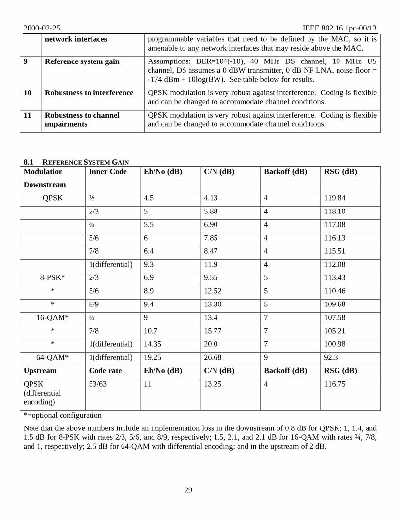
9 Reference system gain Assumptions: BER=10^(-10), 40 MHz DS channel, 10 MHz USchannel, DS assumes a 0 dBW transmitter, 0 dB NF LNA, noise floor =-174 dBm + 10log(BW). See table below for results.
10 Robustness to interference QPSK modulation is very robust against interference. Coding is flexibleand can be changed to accommodate channel conditions.
11 Robustness to channelimpairments
QPSK modulation is very robust against interference. Coding is flexibleand can be changed to accommodate channel conditions.
8.1 REFERENCE SYSTEM GAIN
Modulation Inner Code Eb/No (dB) C/N (dB) Backoff (dB) RSG (dB)
Downstream
QPSK ½ 4.5 4.13 4 119.84
2/3 5 5.88 4 118.10
¾ 5.5 6.90 4 117.08
5/6 6 7.85 4 116.13
7/8 6.4 8.47 4 115.51
1(differential) 9.3 11.9 4 112.08
8-PSK* 2/3 6.9 9.55 5 113.43
* 5/6 8.9 12.52 5 110.46
* 8/9 9.4 13.30 5 109.68
16-QAM* ¾ 9 13.4 7 107.58
* 7/8 10.7 15.77 7 105.21
* 1(differential) 14.35 20.0 7 100.98
64-QAM* 1(differential) 19.25 26.68 9 92.3
Upstream Code rate Eb/No (dB) C/N (dB) Backoff (dB) RSG (dB)
QPSK(differentialencoding)
53/63 11 13.25 4 116.75
*=optional configuration
Note that the above numbers include an implementation loss in the downstream of 0.8 dB for QPSK; 1, 1.4, and1.5 dB for 8-PSK with rates 2/3, 5/6, and 8/9, respectively; 1.5, 2.1, and 2.1 dB for 16-QAM with rates ¾, 7/8,and 1, respectively; 2.5 dB for 64-QAM with differential encoding; and in the upstream of 2 dB.


![Minutes of 802.16 Session #3 [Unapproved] · 1999-10-22 Minutes: 802.16 Meeting#3 802.16-99/08r0 80216-99_08r0.doc 10 Appendix B, Agenda for Opening Plenary 802.16 Session #3 Agenda](https://img.pdfslide.us/doc/110x75/5fad8d3d8973a15bcd789366/minutes-of-80216-session-3-unapproved-1999-10-22-minutes-80216-meeting3-80216-9908r0.jpg)