Embed Size (px)
Citation preview
2
Summary
Physical layer is concerned with the communication of data encoded as signals transmitted over a medium- Fundamental techniques: encoding, modulation, multiplexing
Channel capacity influenced by hardware bandwidth, encoding scheme, transmission impairments (noise and attenuation)
3
Outline
Fundamental concepts- Data, signal, transmission (Ch. 5)- Transmission media (Ch. 7)- Multiplexing (Ch. 11)- Transmission impairments (Ch. 8.2)
Data encoding (Ch. 6, 10) Channel capacity (Ch. 7)
4
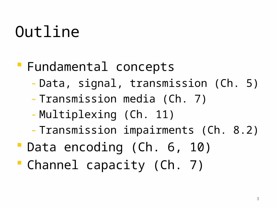
Communication System
Transmitter, receiver, medium
http://i.ehow.com/images/GlobalPhoto/Articles/4996474/illustration-main_Full.jpg
5
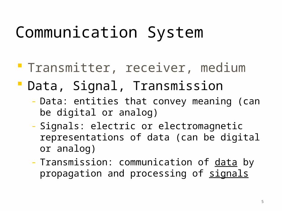
Communication System
Transmitter, receiver, medium Data, Signal, Transmission
- Data: entities that convey meaning (can be digital or analog)
- Signals: electric or electromagnetic representations of data (can be digital or analog)
- Transmission: communication of data by propagation and processing of signals
6
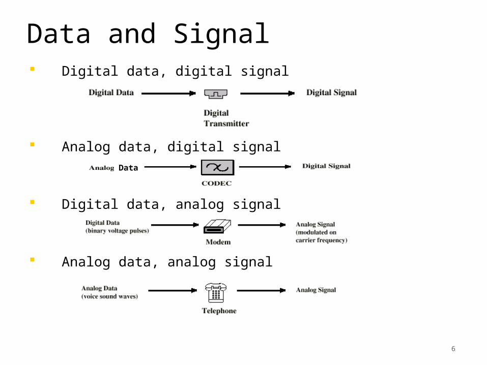
Data and Signal Digital data, digital signal
Analog data, digital signal
Digital data, analog signal
Analog data, analog signal
Data
7
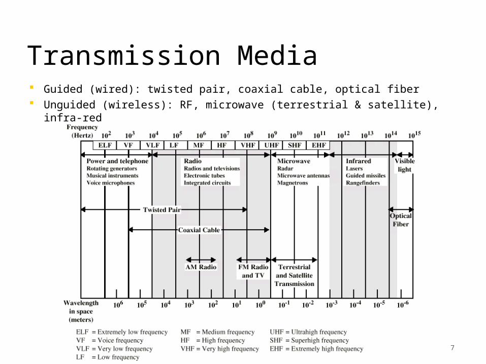
Transmission Media Guided (wired): twisted pair, coaxial cable, optical fiber Unguided (wireless): RF, microwave (terrestrial & satellite),
infra-red
8
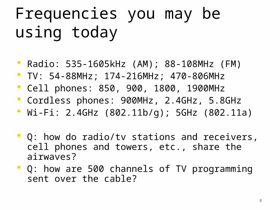
Frequencies you may be using today
Radio: 535-1605kHz (AM); 88-108MHz (FM) TV: 54-88MHz; 174-216MHz; 470-806MHz Cell phones: 850, 900, 1800, 1900MHz Cordless phones: 900MHz, 2.4GHz, 5.8GHz Wi-Fi: 2.4GHz (802.11b/g); 5GHz (802.11a)
Q: how do radio/tv stations and receivers, cell phones and towers, etc., share the airwaves?
Q: how are 500 channels of TV programming sent over the cable?
9
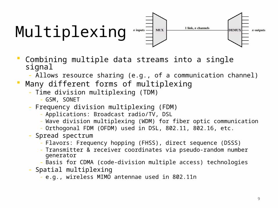
Multiplexing
Combining multiple data streams into a single signal- Allows resource sharing (e.g., of a communication channel)
Many different forms of multiplexing- Time division multiplexing (TDM)
- GSM, SONET- Frequency division multiplexing (FDM)
- Applications: Broadcast radio/TV, DSL- Wave division multiplexing (WDM) for fiber optic communication
- Orthogonal FDM (OFDM) used in DSL, 802.11, 802.16, etc.- Spread spectrum
- Flavors: Frequency hopping (FHSS), direct sequence (DSSS)- Transmitter & receiver coordinates via pseudo-random number generator
- Basis for CDMA (code-division multiple access) technologies- Spatial multiplexing
- e.g., wireless MIMO antennae used in 802.11n
10
Outline
Fundamental concepts- Data, signal, transmission (Ch. 5)- Transmission media (Ch. 7)- Multiplexing (Ch. 11)- Transmission impairments (Ch. 8.2)
Data encoding (Ch. 6, 10) Channel capacity (Ch. 7)
11
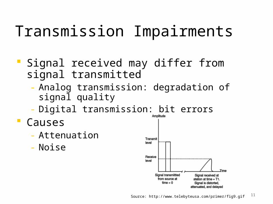
Transmission Impairments
Signal received may differ from signal transmitted- Analog transmission: degradation of signal quality
- Digital transmission: bit errors Causes
- Attenuation- Noise
Source: http://www.telebyteusa.com/primer/fig9.gif
12
Attenuation and Noise
Attenuation- Signal strength falls off with distance- Received signal strength:
- must be enough to be detected- must be sufficiently higher than noise to be received without error
- Attenuation is an increasing function of frequency Noise: additional signals inserted between transmitter and receiver- Thermal: thermal agitation of electrons (also called “white
noise”)- Intermodulation: signals that are the sum and difference of
original frequencies sharing a medium- Crosstalk: signal from one line is picked up by another- Impulse: irregular pulses or spikes that are high in amplitude
and short in duration, e.g., external electromagnetic interference
13
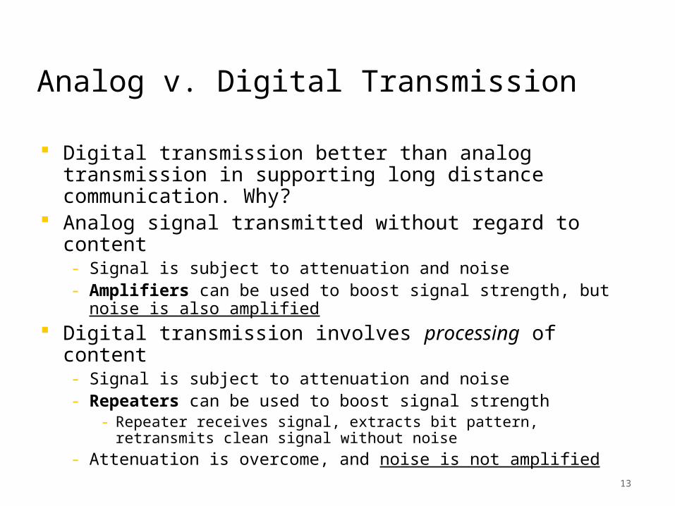
Analog v. Digital Transmission
Digital transmission better than analog transmission in supporting long distance communication. Why?
Analog signal transmitted without regard to content- Signal is subject to attenuation and noise- Amplifiers can be used to boost signal strength, but noise is also amplified
Digital transmission involves processing of content- Signal is subject to attenuation and noise- Repeaters can be used to boost signal strength
- Repeater receives signal, extracts bit pattern, retransmits clean signal without noise
- Attenuation is overcome, and noise is not amplified
14
Outline
Fundamental concepts- Data, signal, transmission (Ch. 5)- Transmission media (Ch. 7)- Multiplexing (Ch. 11)- Transmission impairments (Ch. 8.2)
Data encoding (Ch. 6, 10) Channel capacity (Ch. 7)
15
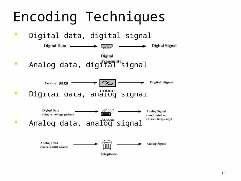
Encoding Techniques Digital data, digital signal
Analog data, digital signal
Digital data, analog signal
Analog data, analog signal
Data
16
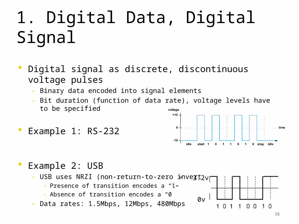
1. Digital Data, Digital Signal
Digital signal as discrete, discontinuous voltage pulses- Binary data encoded into signal elements- Bit duration (function of data rate), voltage levels
have to be specified
Example 1: RS-232
Example 2: USB- USB uses NRZI (non-return-to-zero inverted) encoding
- Presence of transition encodes a “1”- Absence of transition encodes a “0”
- Data rates: 1.5Mbps, 12Mbps, 480Mbps
0v
3.2v
17
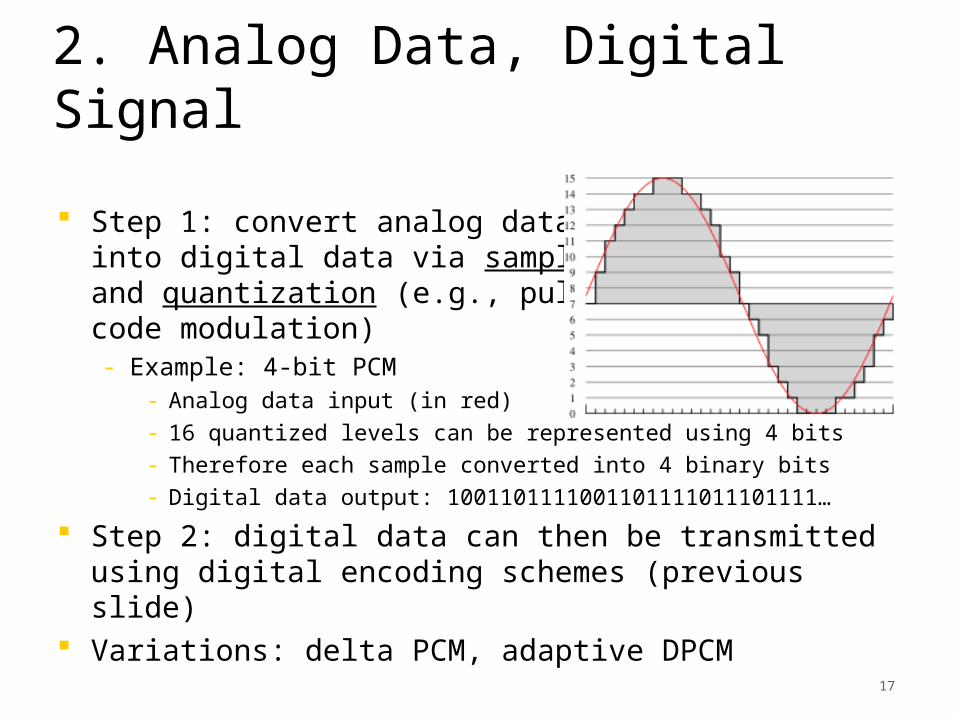
2. Analog Data, Digital Signal
Step 1: convert analog data into digital data via sampling and quantization (e.g., pulse code modulation)- Example: 4-bit PCM
- Analog data input (in red)- 16 quantized levels can be represented using 4 bits- Therefore each sample converted into 4 binary bits- Digital data output: 1001101111001101111011101111…
Step 2: digital data can then be transmitted using digital encoding schemes (previous slide)
Variations: delta PCM, adaptive DPCM
18
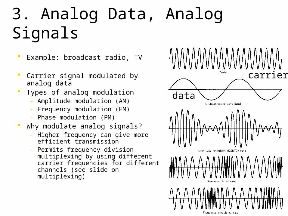
3. Analog Data, Analog Signals
Example: broadcast radio, TV
Carrier signal modulated by analog data
Types of analog modulation- Amplitude modulation (AM)- Frequency modulation (FM)- Phase modulation (PM)
Why modulate analog signals?- Higher frequency can give more
efficient transmission- Permits frequency division
multiplexing by using different carrier frequencies for different channels (see slide on multiplexing)
data
carrier
19
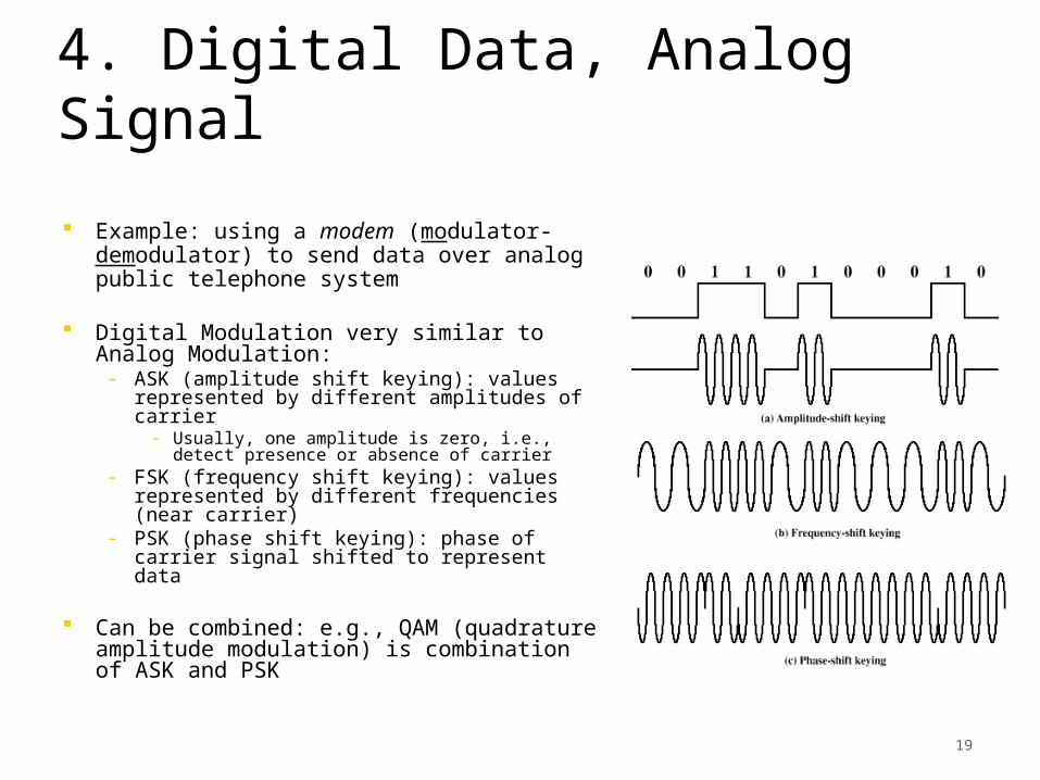
4. Digital Data, Analog Signal
Example: using a modem (modulator-demodulator) to send data over analog public telephone system
Digital Modulation very similar to Analog Modulation:- ASK (amplitude shift keying): values
represented by different amplitudes of carrier- Usually, one amplitude is zero, i.e.,
detect presence or absence of carrier- FSK (frequency shift keying): values
represented by different frequencies (near carrier)
- PSK (phase shift keying): phase of carrier signal shifted to represent data
Can be combined: e.g., QAM (quadrature amplitude modulation) is combination of ASK and PSK
20
Outline
Fundamental concepts- Data, signal, transmission (Ch. 5)- Transmission media (Ch. 7)- Multiplexing (Ch. 11)- Transmission impairments (Ch. 8.2)
Data encoding (Ch. 6, 10) Channel capacity (Ch. 7)
21
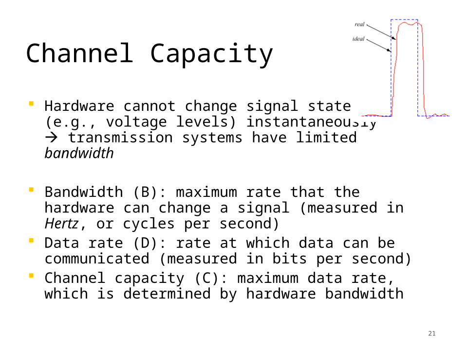
Channel Capacity
Hardware cannot change signal states (e.g., voltage levels) instantaneously transmission systems have limited bandwidth
Bandwidth (B): maximum rate that the hardware can change a signal (measured in Hertz, or cycles per second)
Data rate (D): rate at which data can be communicated (measured in bits per second)
Channel capacity (C): maximum data rate, which is determined by hardware bandwidth
22
Channel Capacity
Nyquist (1928): D < 2B- the number of independent pulses that could be put through a telegraph channel per unit time is limited to twice the bandwidth of the channel
Hartley (1928): D < 2B log2(K)- where K is the number of distinct messages that can be sent
- Nyquist result is special case of K=2
23
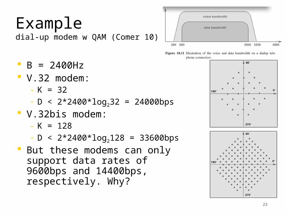
Exampledial-up modem w QAM (Comer 10)
B = 2400Hz V.32 modem:
- K = 32- D < 2*2400*log232 = 24000bps
V.32bis modem:- K = 128- D < 2*2400*log2128 = 33600bps
But these modems can only support data rates of 9600bps and 14400bps, respectively. Why?
24
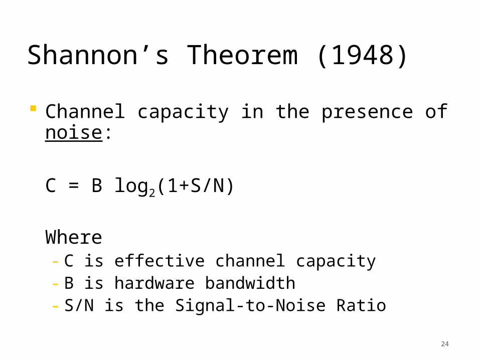
Shannon’s Theorem (1948)
Channel capacity in the presence of noise:
C = B log2(1+S/N)
Where- C is effective channel capacity- B is hardware bandwidth- S/N is the Signal-to-Noise Ratio
25
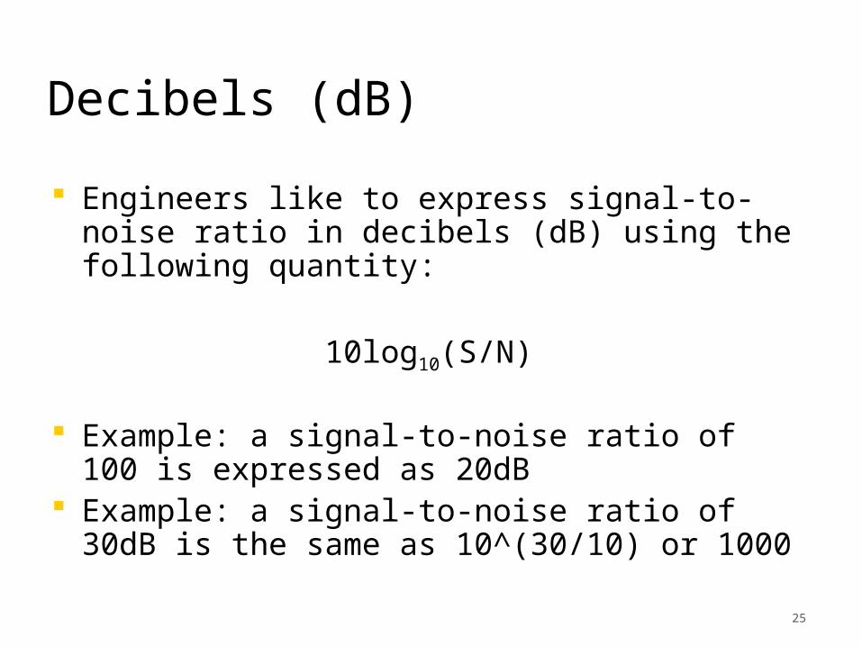
Decibels (dB)
Engineers like to express signal-to-noise ratio in decibels (dB) using the following quantity:
10log10(S/N)
Example: a signal-to-noise ratio of 100 is expressed as 20dB
Example: a signal-to-noise ratio of 30dB is the same as 10^(30/10) or 1000
26
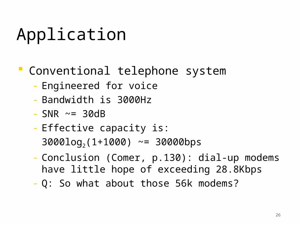
Application
Conventional telephone system- Engineered for voice- Bandwidth is 3000Hz- SNR ~= 30dB- Effective capacity is:
3000log2(1+1000) ~= 30000bps
- Conclusion (Comer, p.130): dial-up modems have little hope of exceeding 28.8Kbps
- Q: So what about those 56k modems?
27
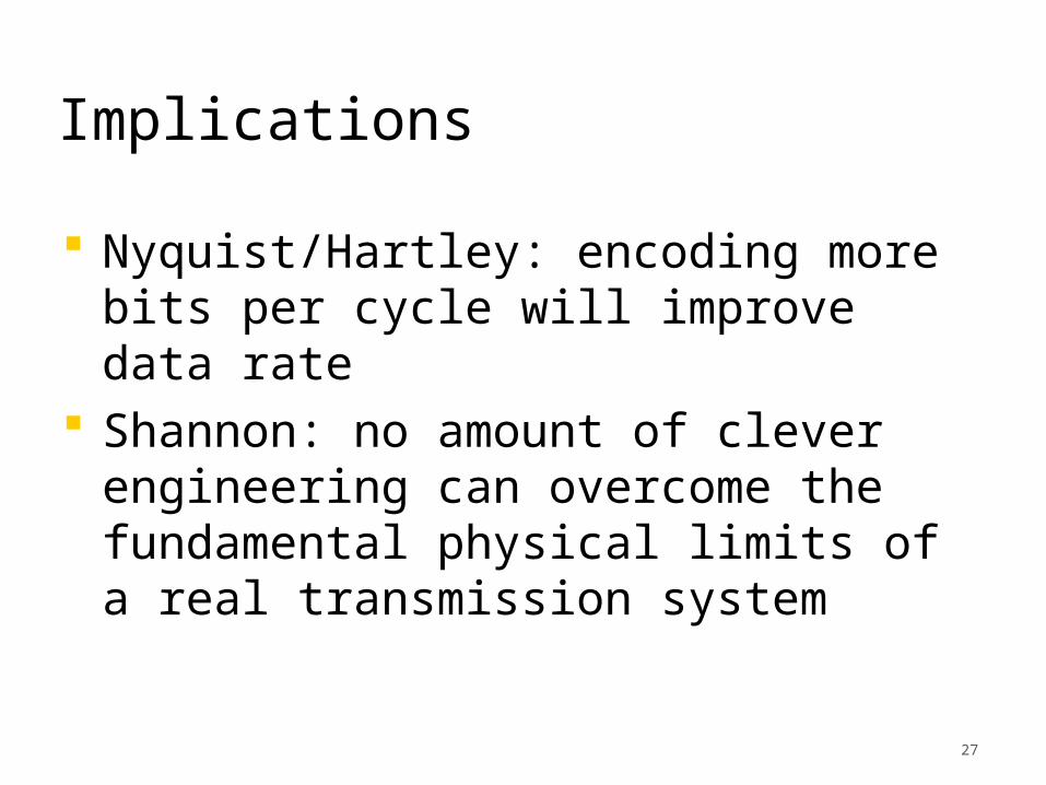
Implications
Nyquist/Hartley: encoding more bits per cycle will improve data rate
Shannon: no amount of clever engineering can overcome the fundamental physical limits of a real transmission system

28
Summary
Physical layer is concerned with the communication of data encoded as signals transmitted over a medium- Fundamental techniques: encoding, modulation, multiplexing
Channel capacity influenced by hardware bandwidth, encoding scheme, transmission impairments (noise and attenuation)