Embed Size (px)
Citation preview
Physical Layer Architecture andError Correction Codes
Rigato Lorenzo – Computer Science StudentDISI – University of Trento
Advanced Networking 2012-2013
Email: [email protected]
Introduction - Goals
SEMINAR GOALS
How a signal can be digitally transmitted over a network
Which are the main problems that engineer must solve to have an efficient network to communicate
Which are the techniques that permits error recovery when something goes wrong during communication
Let's Start!!
Introduction - Architecture of Communication System
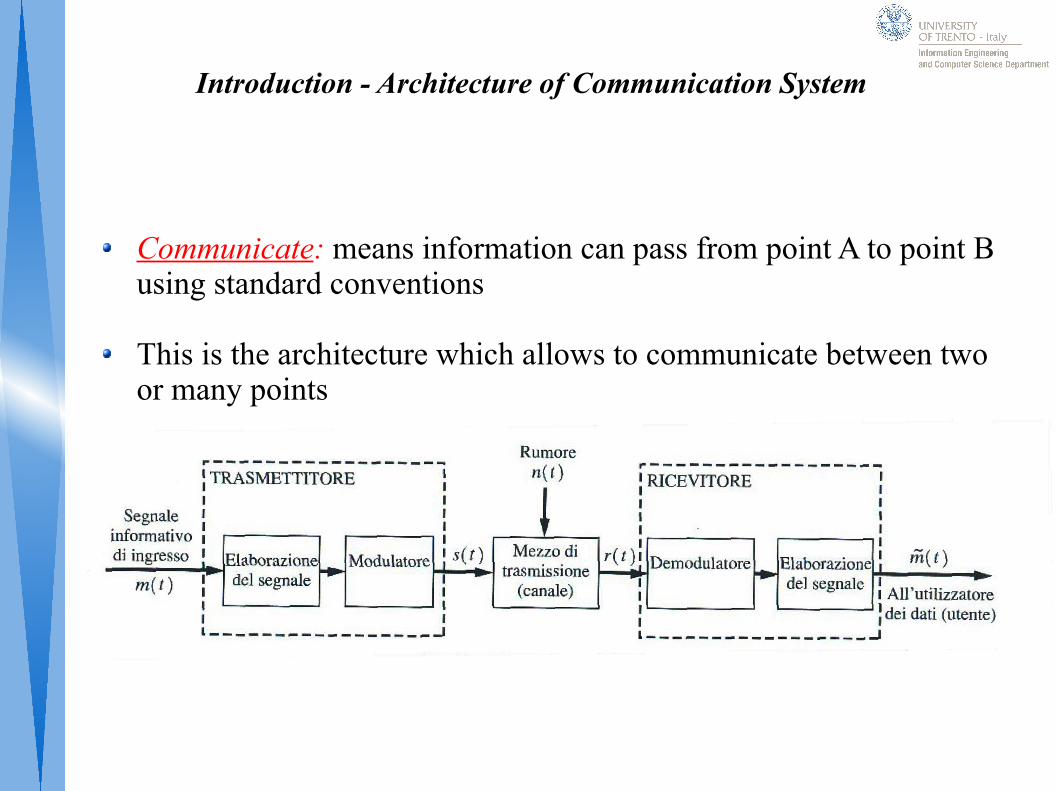
Communicate: means information can pass from point A to point B using standard conventions
This is the architecture which allows to communicate between two or many points

Chapter 1 - Signals
What is a Signal?
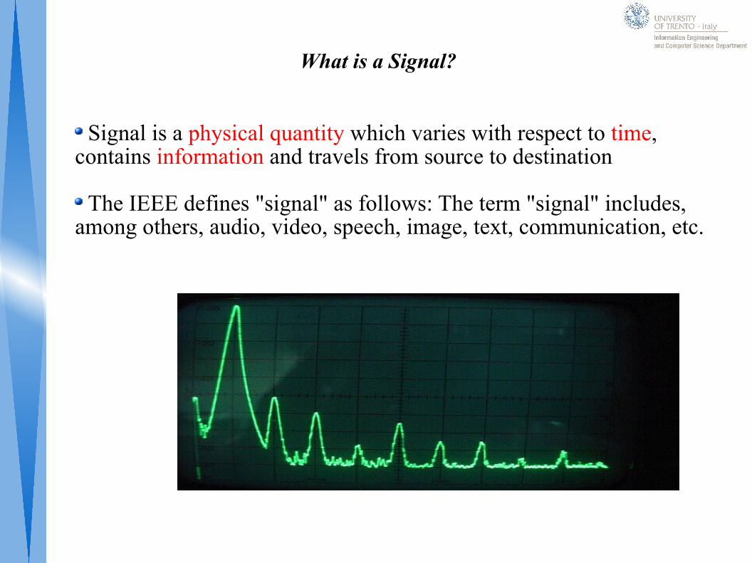
Signal is a physical quantity which varies with respect to time, contains information and travels from source to destination
The IEEE defines "signal" as follows: The term "signal" includes, among others, audio, video, speech, image, text, communication, etc.
Analog signal
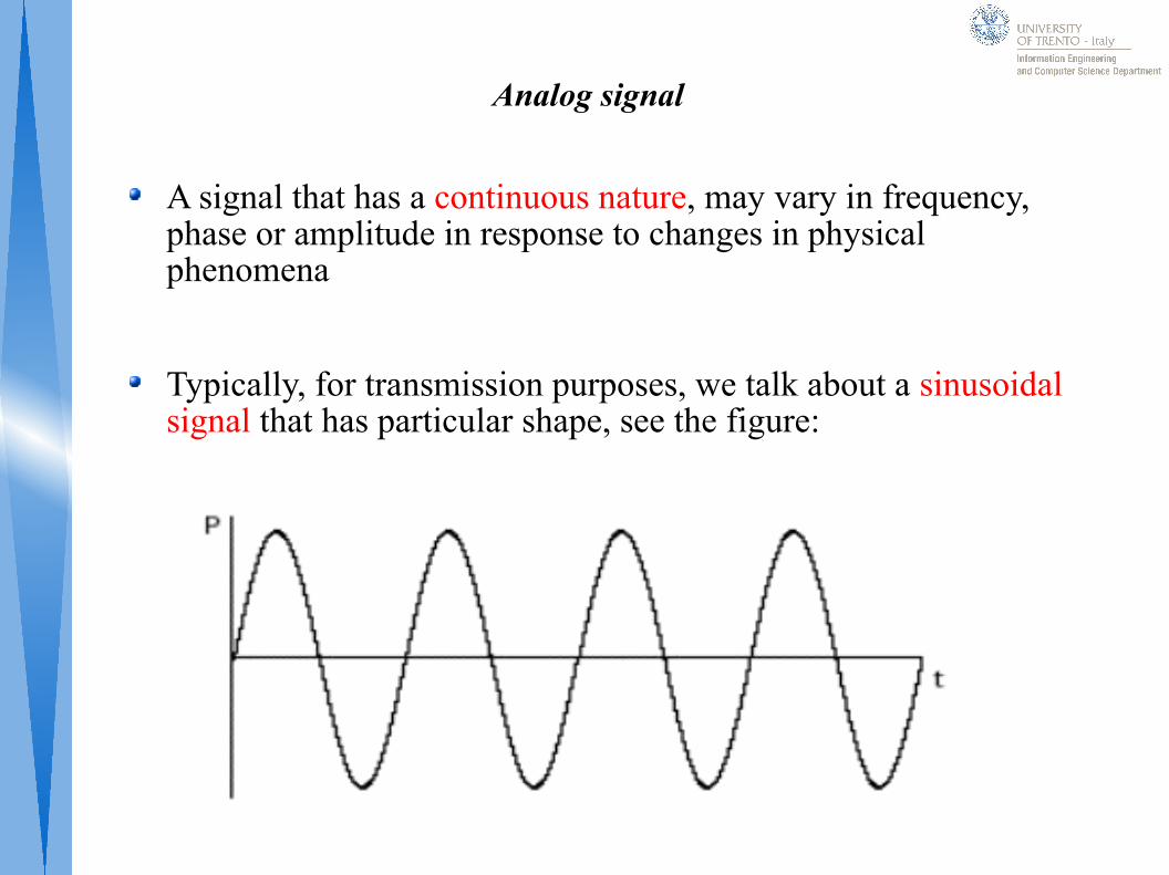
A signal that has a continuous nature, may vary in frequency, phase or amplitude in response to changes in physical phenomena
Typically, for transmission purposes, we talk about a sinusoidal signal that has particular shape, see the figure:
s(t) = A sin(2π f t) + Φ
Properties of Sinusoidal Signal
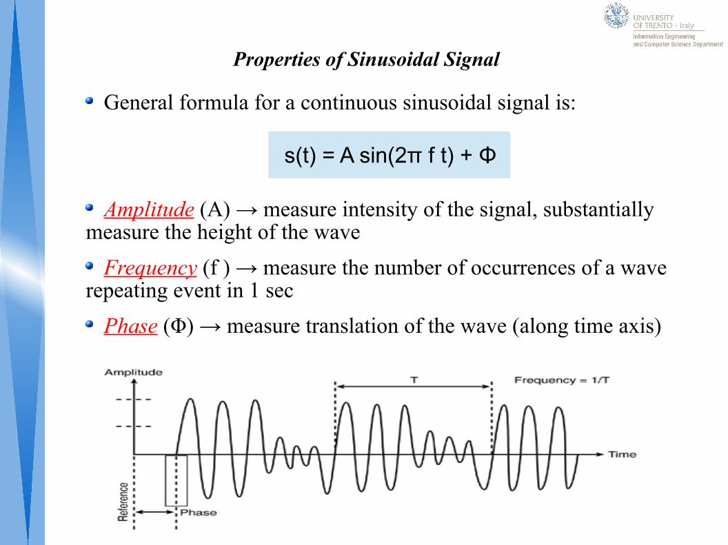
General formula for a continuous sinusoidal signal is:
Amplitude (A) → measure intensity of the signal, substantially measure the height of the wave
Frequency (f ) → measure the number of occurrences of a wave repeating event in 1 sec
Phase (Φ) → measure translation of the wave (along time axis)
Digital Signal
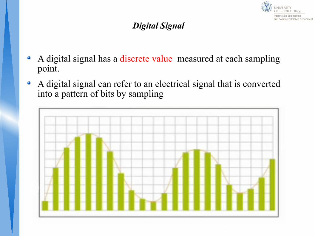
A digital signal has a discrete value measured at each sampling point.
A digital signal can refer to an electrical signal that is converted into a pattern of bits by sampling
Sampling
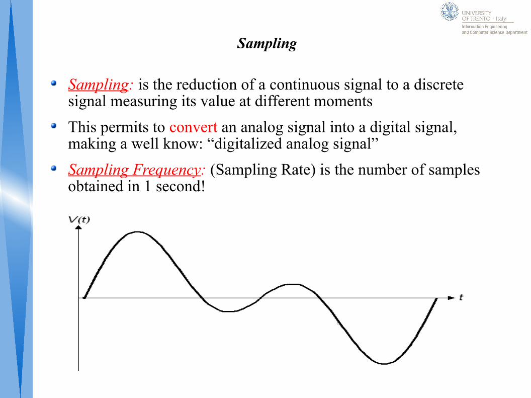
Sampling: is the reduction of a continuous signal to a discrete signal measuring its value at different moments
This permits to convert an analog signal into a digital signal, making a well know: “digitalized analog signal”
Sampling Frequency: (Sampling Rate) is the number of samples obtained in 1 second!
Chapter 2 – Transmission
Transmission
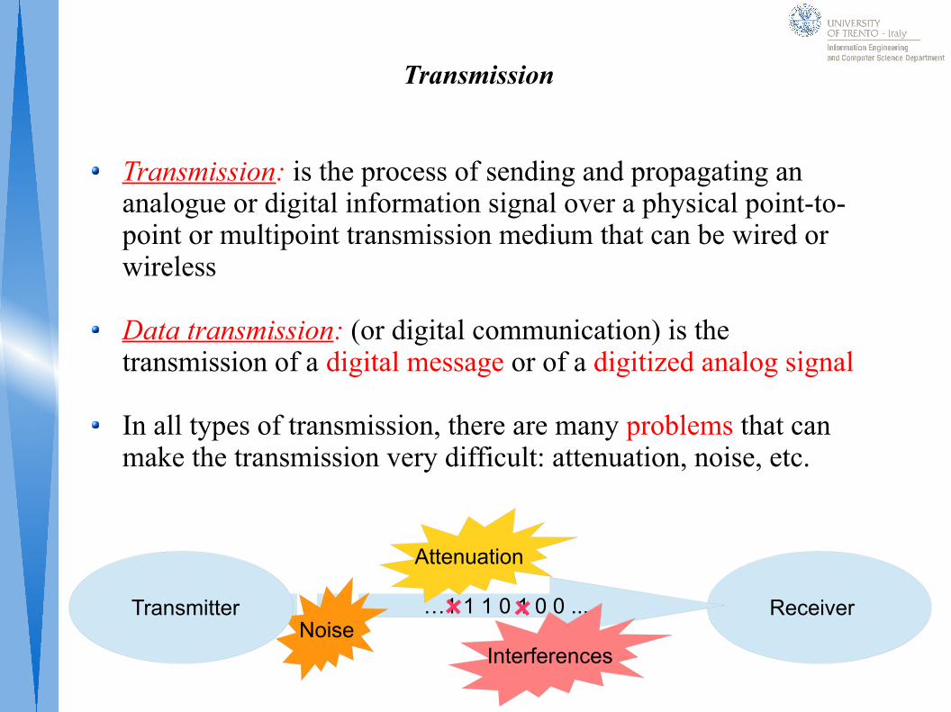
Transmission: is the process of sending and propagating an analogue or digital information signal over a physical point-to-point or multipoint transmission medium that can be wired or wireless
Data transmission: (or digital communication) is the transmission of a digital message or of a digitized analog signal
In all types of transmission, there are many problems that can make the transmission very difficult: attenuation, noise, etc.
Receiver…1 1 1 0 1 0 0 ...Noise
Transmitter
Attenuation
Interferences
Attenuation
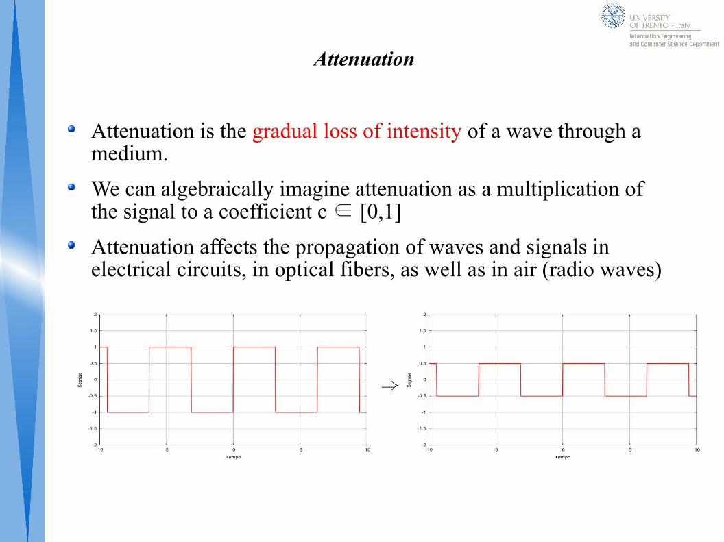
Attenuation is the gradual loss of intensity of a wave through a medium.
We can algebraically imagine attenuation as a multiplication of the signal to a coefficient c ∈ [0,1]
Attenuation affects the propagation of waves and signals in electrical circuits, in optical fibers, as well as in air (radio waves)
Interference
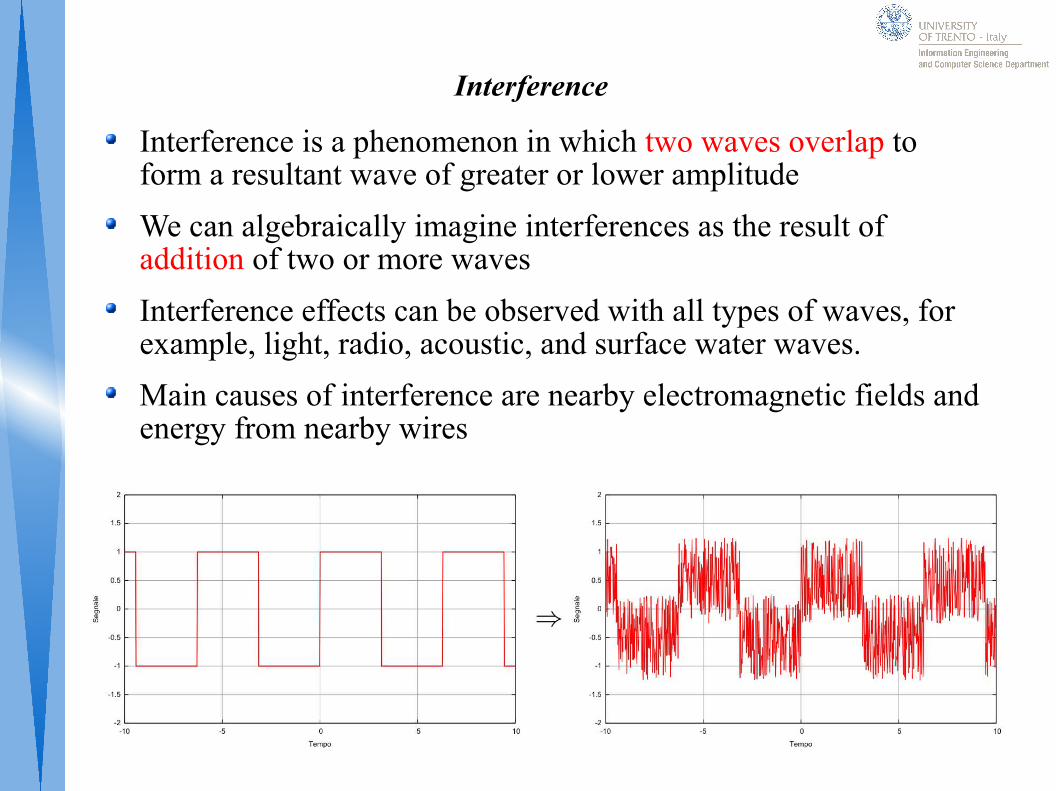
Interference is a phenomenon in which two waves overlap to form a resultant wave of greater or lower amplitude
We can algebraically imagine interferences as the result of addition of two or more waves
Interference effects can be observed with all types of waves, for example, light, radio, acoustic, and surface water waves.
Main causes of interference are nearby electromagnetic fields and energy from nearby wires
Distortion
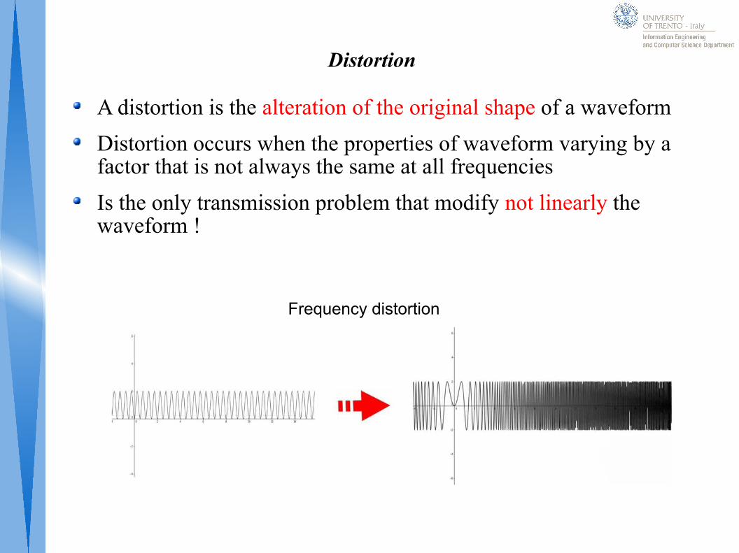
A distortion is the alteration of the original shape of a waveform
Distortion occurs when the properties of waveform varying by a factor that is not always the same at all frequencies
Is the only transmission problem that modify not linearly the waveform !
Frequency distortion
Chapter 3- Encoding
Encoding
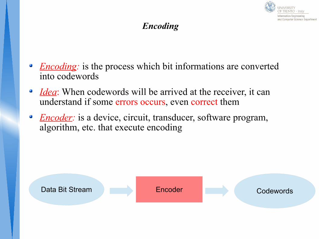
Encoding: is the process which bit informations are converted into codewords
Idea: When codewords will be arrived at the receiver, it can understand if some errors occurs, even correct them
Encoder: is a device, circuit, transducer, software program, algorithm, etc. that execute encoding
Data Bit Stream CodewordsEncoder
Decoding
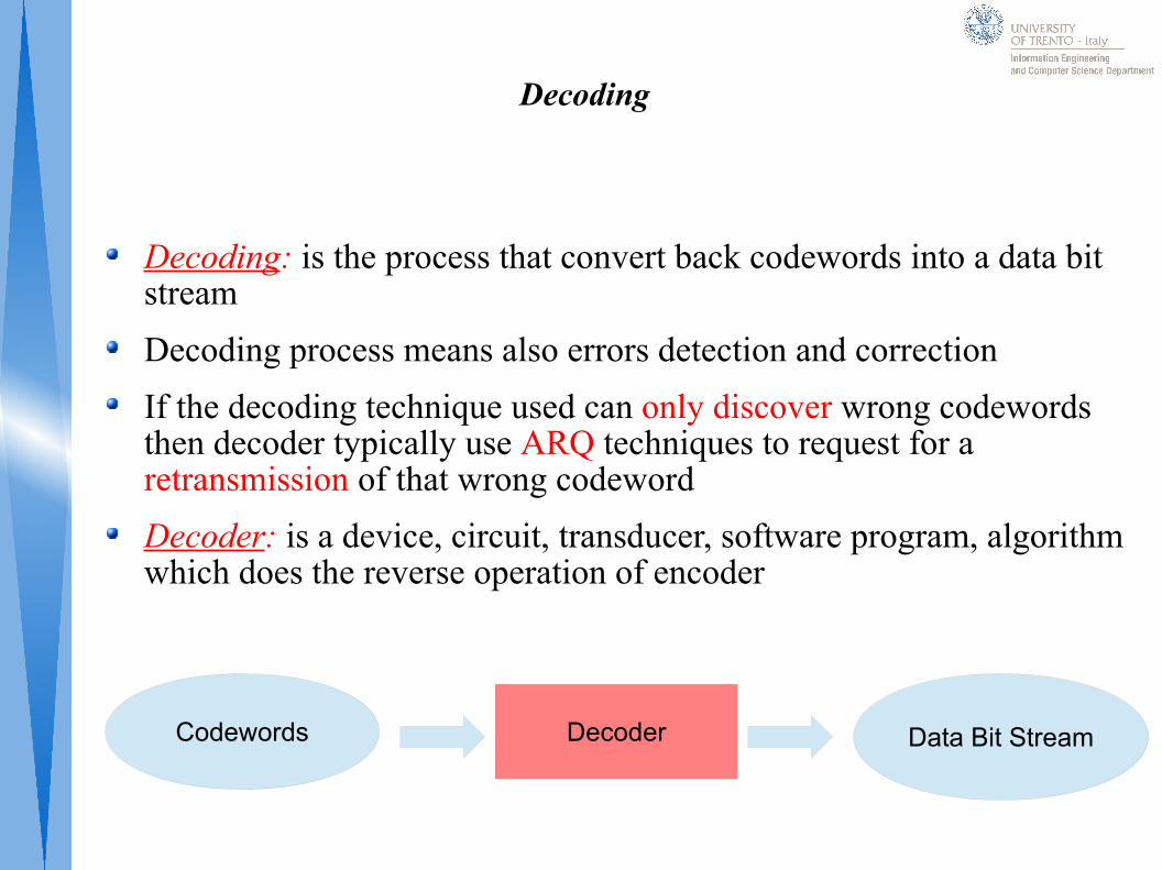
Decoding: is the process that convert back codewords into a data bit stream
Decoding process means also errors detection and correction
If the decoding technique used can only discover wrong codewords then decoder typically use ARQ techniques to request for a retransmission of that wrong codeword
Decoder: is a device, circuit, transducer, software program, algorithm which does the reverse operation of encoder
Codewords Data Bit StreamDecoder
ARQ (Automatic Repeat Re-Quest)
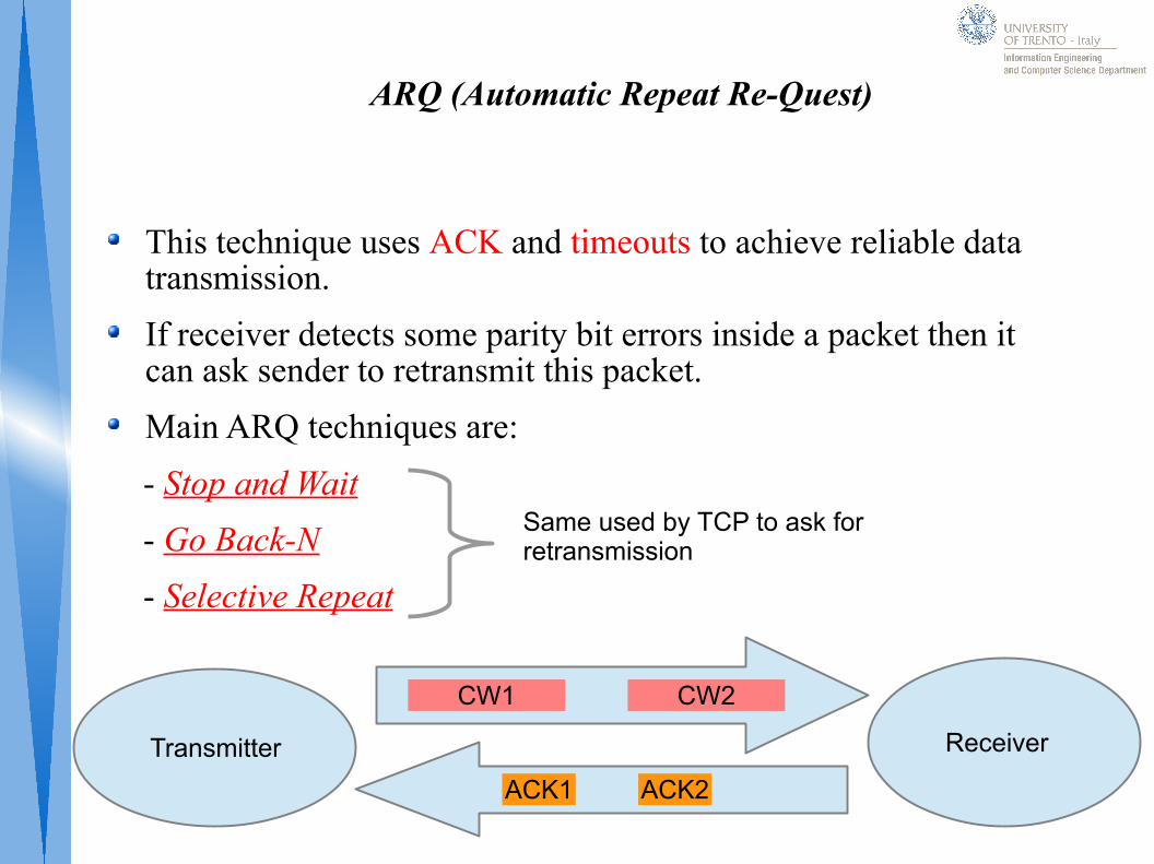
This technique uses ACK and timeouts to achieve reliable data transmission.
If receiver detects some parity bit errors inside a packet then it can ask sender to retransmit this packet.
Main ARQ techniques are:
- Stop and Wait
- Go Back-N
- Selective Repeat
Receiver Transmitter
CW2CW1
ACK1 ACK2
Same used by TCP to ask for retransmission
FEC (Forward Error Correction)
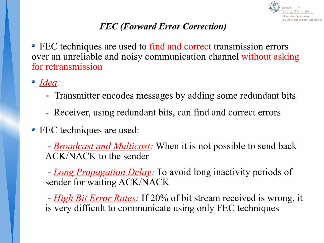
FEC techniques are used to find and correct transmission errors over an unreliable and noisy communication channel without asking for retransmission
Idea:
FEC techniques are used:
- Broadcast and Multicast: When it is not possible to send back ACK/NACK to the sender
- Long Propagation Delay: To avoid long inactivity periods of sender for waiting ACK/NACK
- High Bit Error Rates: If 20% of bit stream received is wrong, it is very difficult to communicate using only FEC techniques
- Transmitter encodes messages by adding some redundant bits
- Receiver, using redundant bits, can find and correct errors
Block Code
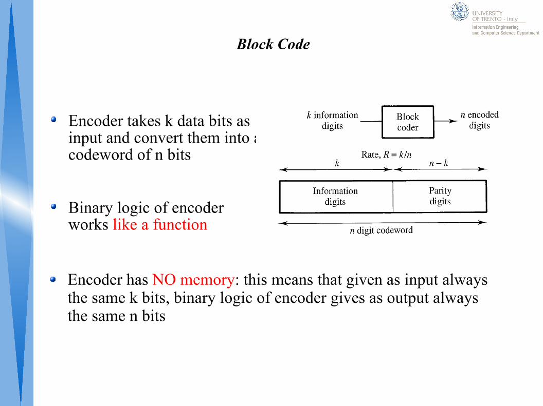
Encoder takes k data bits as input and convert them into a codeword of n bits
Binary logic of encoder works like a function
Encoder has NO memory: this means that given as input always the same k bits, binary logic of encoder gives as output always the same n bits
Hamming
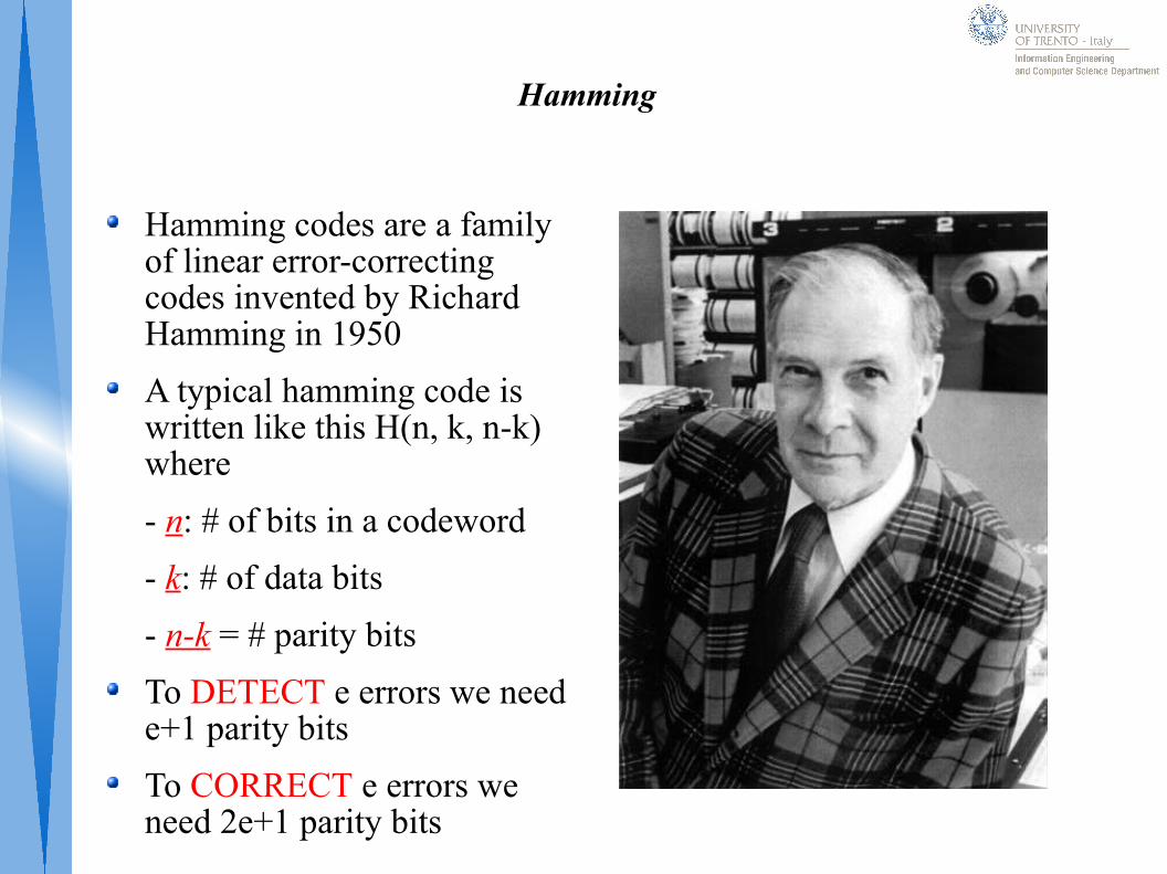
Hamming codes are a family of linear error-correcting codes invented by Richard Hamming in 1950
A typical hamming code is written like this H(n, k, n-k) where
- n: # of bits in a codeword
- k: # of data bits
- n-k = # parity bits
To DETECT e errors we need e+1 parity bits
To CORRECT e errors we need 2e+1 parity bits
Hamming Definitions
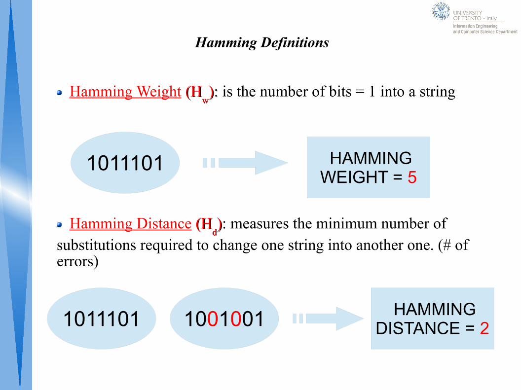
Hamming Weight (H(Hww)): : is the number of bits = 1 into a string
Hamming Distance (H(Hdd)): measures the minimum number of
substitutions required to change one string into another one. (# of errors)
1011101 1001001 HAMMINGDISTANCE = 2
1011101 HAMMINGWEIGHT = 5
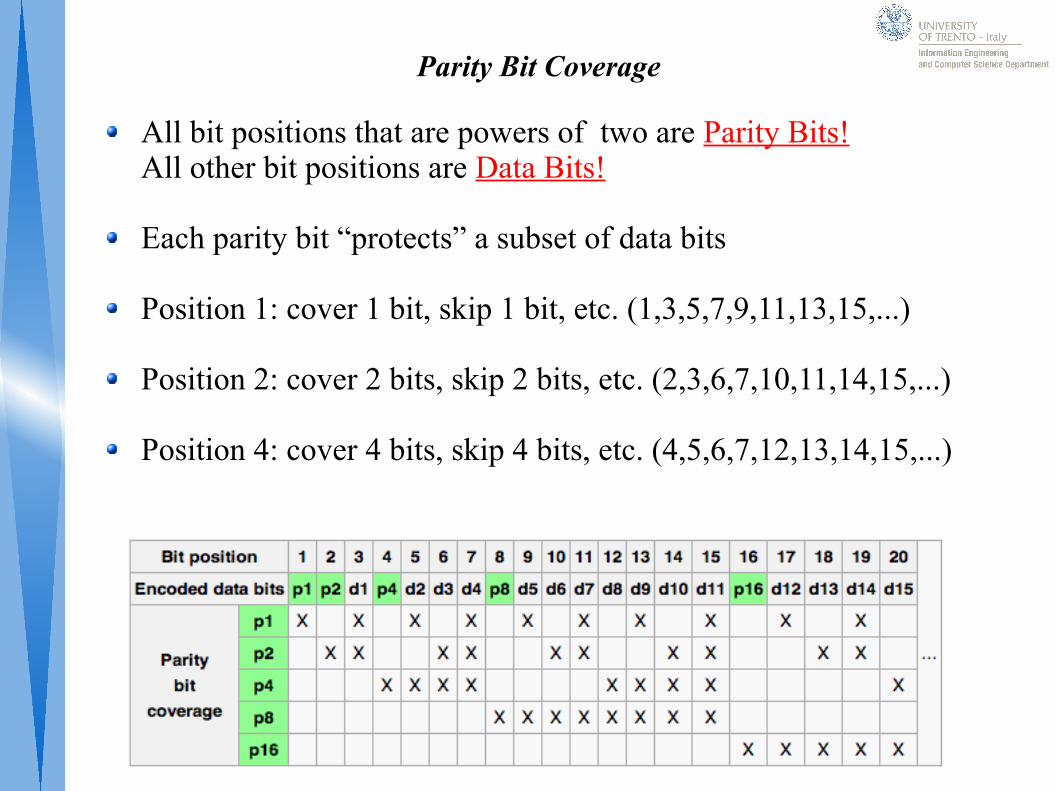
Parity Bit Coverage
All bit positions that are powers of two are Parity Bits!All other bit positions are Data Bits!
Each parity bit “protects” a subset of data bits
Position 1: cover 1 bit, skip 1 bit, etc. (1,3,5,7,9,11,13,15,...)
Position 2: cover 2 bits, skip 2 bits, etc. (2,3,6,7,10,11,14,15,...)
Position 4: cover 4 bits, skip 4 bits, etc. (4,5,6,7,12,13,14,15,...)
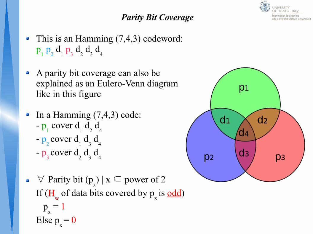
Parity Bit Coverage
This is an Hamming (7,4,3) codeword: p
1 p
2 d
1 p
3 d
2 d
3 d
4
A parity bit coverage can also be explained as an Eulero-Venn diagramlike in this figure
In a Hamming (7,4,3) code:- p
1 cover d
1 d
2 d
4
- p2 cover d
1 d
3 d
4
- p3 cover d
2 d
3 d
4
∀ Parity bit (px) | x ∈ power of 2
If (HHww of data bits covered by p
x is odd)
px = 1
Else px = 0
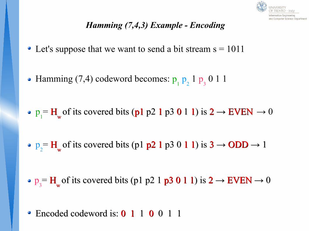
Hamming (7,4,3) Example - Encoding
Let's suppose that we want to send a bit stream s = 1011
Hamming (7,4) codeword becomes: p1 p
2 1 p
3 0 1 1
p1= HH
w w of its covered bits (of its covered bits (p1p1 p2 p2 1 1 p3p3 0 0 1 1 11) is ) is 22 → → EVENEVEN
→ 0
p2= HH
w w of its covered bits (p1 of its covered bits (p1 p2p2 1 1 p3 0 p3 0 11 11) is ) is 33 → → ODD ODD → 1→ 1
p
3= HH
w w of its covered bits (p1 p2 1 of its covered bits (p1 p2 1 p3p3 00 11 11) is ) is 22 → → EVEN EVEN → 0→ 0
Encoded codeword is: Encoded codeword is: 0 10 1 1 1 00 0 1 1 0 1 1
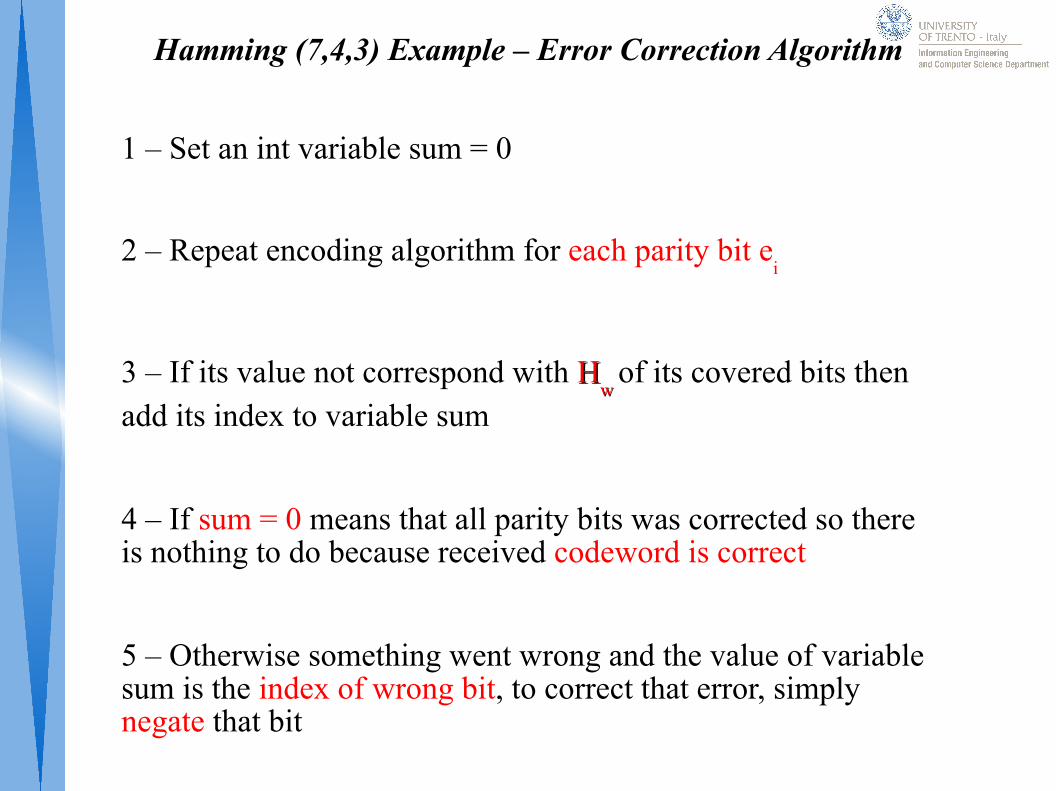
Hamming (7,4,3) Example – Error Correction Algorithm
1 – Set an int variable sum = 0
2 – Repeat encoding algorithm for each parity bit ei
3 – If its value not correspond with HHw w
of its covered bits then add its index to variable sum
4 – If sum = 0 means that all parity bits was corrected so there is nothing to do because received codeword is correct
5 – Otherwise something went wrong and the value of variable sum is the index of wrong bit, to correct that error, simply negate that bit
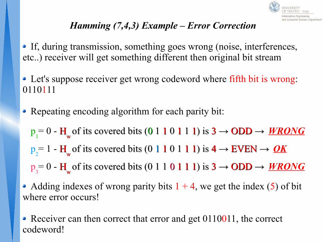
Hamming (7,4,3) Example – Error Correction
If, during transmission, something goes wrong (noise, interferences, etc..) receiver will get something different then original bit stream
Let's suppose receiver get wrong codeword where fifth bit is wrong: 0110111
Repeating encoding algorithm for each parity bit:
p1= 0 - HH
w w of its covered bits (of its covered bits (00 1 1 1 1 00 1 1 1 1 11) is ) is 33 → → ODDODD → →
WRONG
p2= 1 - HH
w w of its covered bits (0 of its covered bits (0 11 1 1 0 1 0 1 1 11 1) is ) is 44 → → EVENEVEN → →
OK
p3= 0 - HH
w w of its covered bits (0 1 1of its covered bits (0 1 1 00 11 1 11 1) is ) is 33 → → ODDODD → →
WRONG
Adding indexes of wrong parity bits 1 + 4, we get the index (5) of bit where error occurs!
Receiver can then correct that error and get 0110011, the correct codeword!
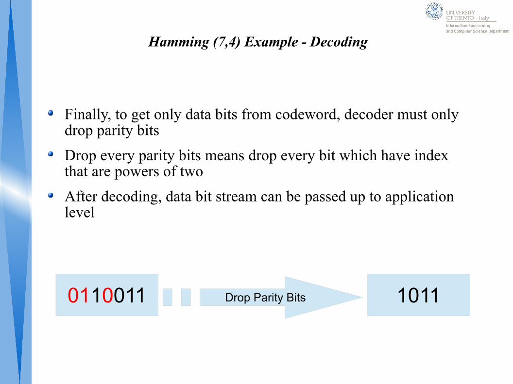
Hamming (7,4) Example - Decoding
Finally, to get only data bits from codeword, decoder must only drop parity bits
Drop every parity bits means drop every bit which have index that are powers of two
After decoding, data bit stream can be passed up to application level
0110011 Drop Parity Bits 1011
Galois Field
A Galois field GF(x): is a finite field that contains a finite number of elements, x specify cardinality of GF
A GF has these properties:- Closing under Addition and Multiplication- Associativity, Commutativity and Distributivity- Existence of neutral element: 0 for addition and 1 for multiplication- Existence for each element u of its opposite -u- Existence for each element u ≠ 0, the inverse element u-1
In Addition and Subtraction are executed with XOR operand
In Division, dividend is divisible by divisor only if it is composed by the same number of bits of divisor otherwise not!
In Multiplication the result must be divided by cardinality of Galois Field considered and take the remainder as right result!
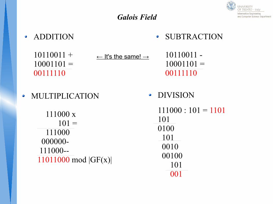
Galois Field
ADDITION
10110011 + 10001101 =00111110
SUBTRACTION
10110011 -10001101 =00111110
MULTIPLICATION
111000 x 101 = 111000 000000- 111000-- 11011000 mod |GF(x)|
DIVISION
111000 : 101 = 11011010100 101 0010 00100 101 001
← It's the same! →
CRC (Cyclic Redundancy Code)
CRC Code checks if transmission errors occurs but not correct them.
A bit stream of k bits can be converted in a polynomial of degree k-1
CRC uses Galois Field to encode messages
Es. 100110 (k = 6) can be converted in a polynomial like this: x5 + x2 + x. Degree = k-1
Generator Polynomial g(x) is an algebraic polynomial of degree r (composed by r+1 bits) where FIRST and LAST bits = 1;
g(x) is always known by transmitter and receiver
CRC – Encoding Algorithm
1. Let's suppose m(x) is message that we want encode
2. Add r zero bits to m(x) (r is degree of g(x))
3. r(x) = xrm(x) mod g(x)
4. m(x) = xrm(x) – r(x) (it is a XOR operation of last r bits)
5. Transmit this new polynomial m(x) where first m bits, data bits, are unchanged
CRC (Cyclic Redundancy Code)
Message is another polynomial m(x) of degree m-1 where m > r
IDEA: Append at m(x) a control bit string of r bits to get a polynomial divisible by g(x)
If transmission works, decoder divide m(x) by g(x) and get no rest. This means that codeword is correctly received
To decode m(x), decoder must divide m(x) by xr to get only data bits.
Otherwise, if transmission errors occurs, with very high probability, that polynomial will not be more divisible by g(x)
Decoder must ask for a retransmission of that wrong packet using ARQ
Reed Solomon – RS Code
RS-codes are non-binary cyclic error-correcting codes invented by Irving S. Reed and Gustave Solomon
Like CRC it see a bit stream like a polynomial
RS-Code use algebraically properties of Galois Field to encoding
RS-Code purpose is to find greater number of packets that contains errors.
RS-Code are used in our Digital TV
Reed Solomon - RS Code
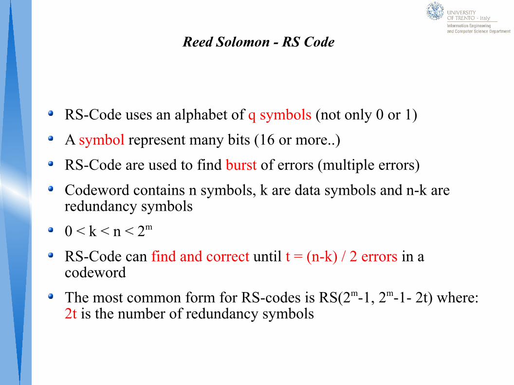
RS-Code uses an alphabet of q symbols (not only 0 or 1)
A symbol represent many bits (16 or more..)
RS-Code are used to find burst of errors (multiple errors)
Codeword contains n symbols, k are data symbols and n-k are redundancy symbols
0 < k < n < 2m
RS-Code can find and correct until t = (n-k) / 2 errors in a codeword
The most common form for RS-codes is RS(2m-1, 2m-1- 2t) where: 2t is the number of redundancy symbols
RS-Code – Encoding Algorithm
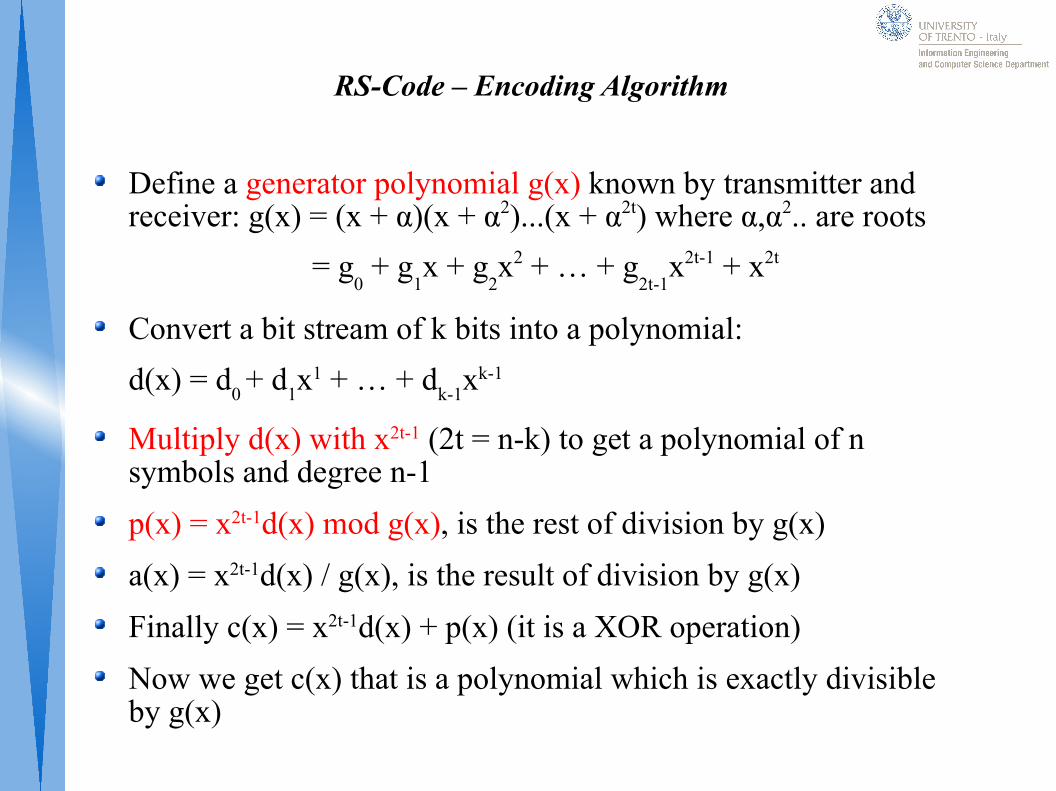
Define a generator polynomial g(x) known by transmitter and receiver: g(x) = (x + α)(x + α2)...(x + α2t) where α,α2.. are roots
= g0 + g
1x + g
2x2 + … + g
2t-1x2t-1 + x2t
Convert a bit stream of k bits into a polynomial:
d(x) = d0 + d
1x1 + … + d
k-1xk-1
Multiply d(x) with x2t-1 (2t = n-k) to get a polynomial of n symbols and degree n-1
p(x) = x2t-1d(x) mod g(x), is the rest of division by g(x)
a(x) = x2t-1d(x) / g(x), is the result of division by g(x)
Finally c(x) = x2t-1d(x) + p(x) (it is a XOR operation)
Now we get c(x) that is a polynomial which is exactly divisible by g(x)
RS Code – Decoding
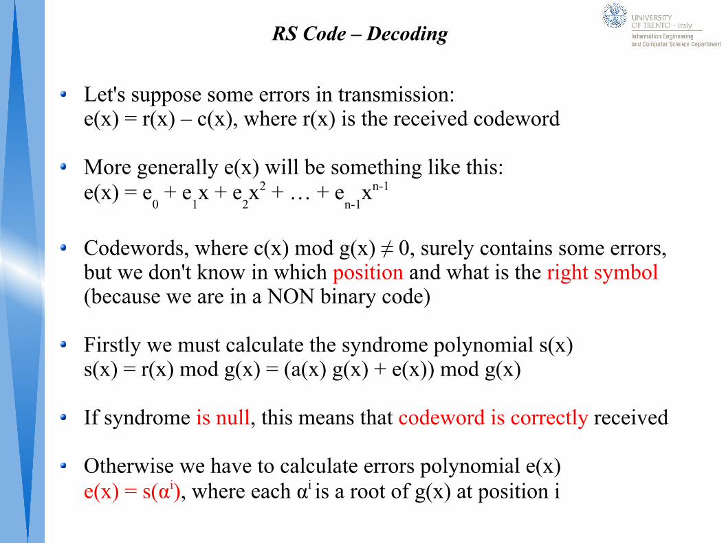
Let's suppose some errors in transmission:e(x) = r(x) – c(x), where r(x) is the received codeword
More generally e(x) will be something like this:e(x) = e
0 + e
1x + e
2x2 + … + e
n-1xn-1
Codewords, where c(x) mod g(x) ≠ 0, surely contains some errors, but we don't know in which position and what is the right symbol (because we are in a NON binary code)
Firstly we must calculate the syndrome polynomial s(x)s(x) = r(x) mod g(x) = (a(x) g(x) + e(x)) mod g(x)
If syndrome is null, this means that codeword is correctly received
Otherwise we have to calculate errors polynomial e(x)e(x) = s(αi), where each αi is a root of g(x) at position i
RS Code – Decoding
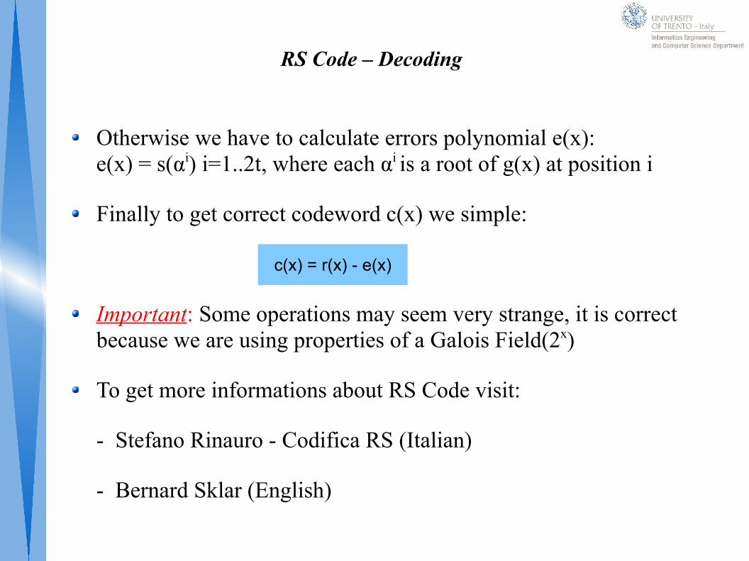
Otherwise we have to calculate errors polynomial e(x):e(x) = s(αi) i=1..2t, where each αi is a root of g(x) at position i
Finally to get correct codeword c(x) we simple:
Important: Some operations may seem very strange, it is correct because we are using properties of a Galois Field(2x)
To get more informations about RS Code visit:
- Stefano Rinauro - Codifica RS (Italian)
- Bernard Sklar (English)
c(x) = r(x) - e(x)
Convolutional Code
Encoder has a little memory to remind previous states
Encoder use a scrolling register to store until K bit stream blocks past
Constraint Length: Number of bit stream blocks (K) stored into the scrolling register
From these K-1 blocks plus the new one, binary logic calculate the new codeword
Infinite Memory: Because a convolutional encoder can remember K previous states, we say that it remember infinite previous states because each state depends by K before, and so on
Convolutional Code – Encoding Example
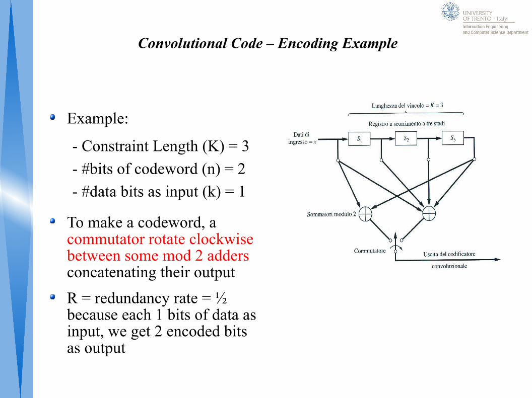
Example:
To make a codeword, a commutator rotate clockwise between some mod 2 adders concatenating their output
R = redundancy rate = ½ because each 1 bits of data as input, we get 2 encoded bits as output
- Constraint Length (K) = 3
- #bits of codeword (n) = 2
- #data bits as input (k) = 1
Convolutional Code – Encoding Example
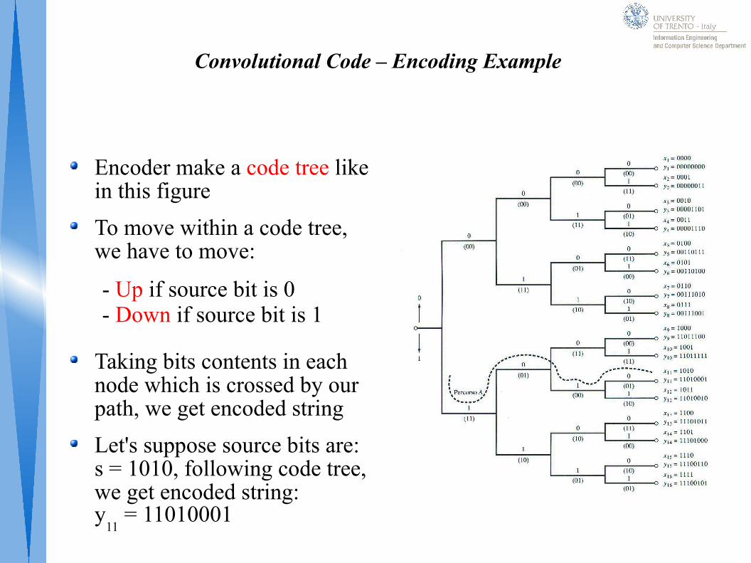
Encoder make a code tree like in this figure
To move within a code tree, we have to move:
Taking bits contents in each node which is crossed by our path, we get encoded string
Let's suppose source bits are: s = 1010, following code tree, we get encoded string: y
11 = 11010001
- Up if source bit is 0- Down if source bit is 1
Convolutional Code – Decoding Example
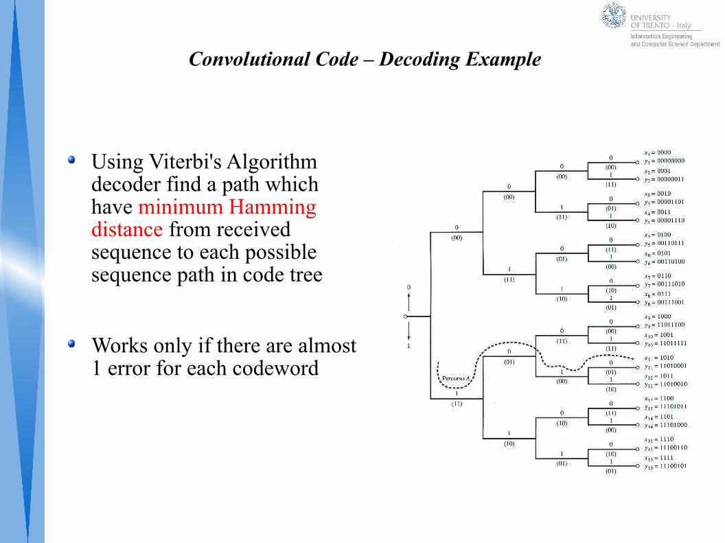
Using Viterbi's Algorithm decoder find a path which have minimum Hamming distance from received sequence to each possible sequence path in code tree
Works only if there are almost 1 error for each codeword
Chapter 4 – Modulation
Modulation
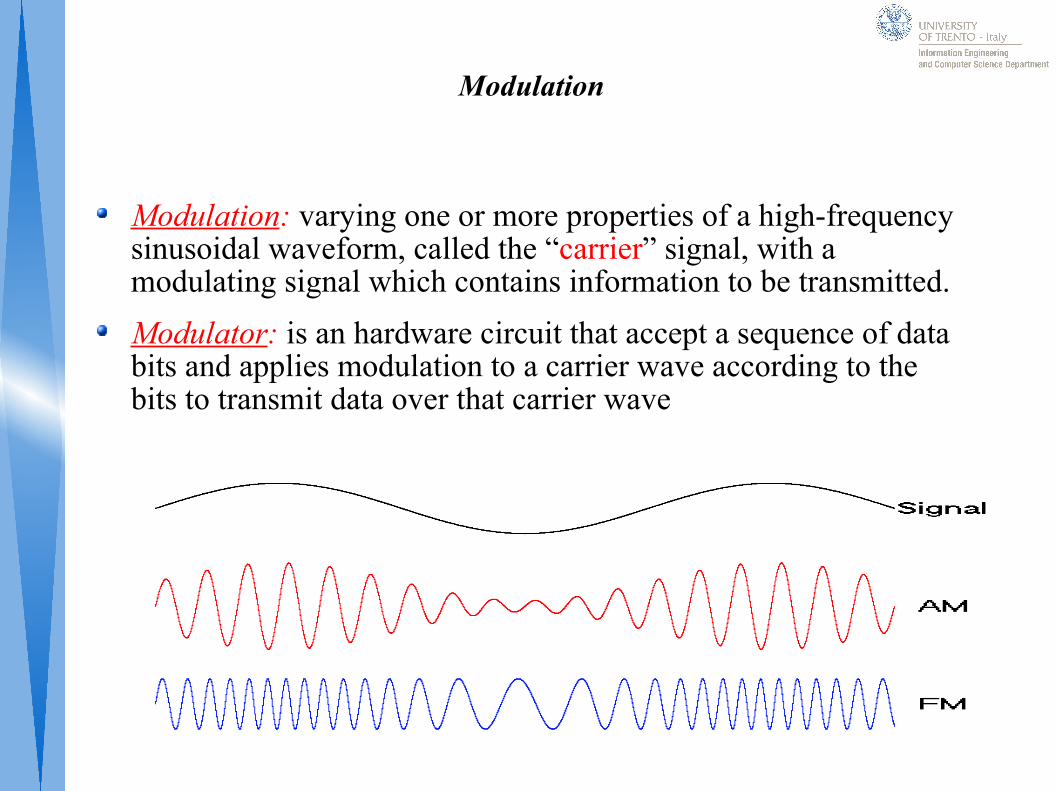
Modulation: varying one or more properties of a high-frequency sinusoidal waveform, called the “carrier” signal, with a modulating signal which contains information to be transmitted.
Modulator: is an hardware circuit that accept a sequence of data bits and applies modulation to a carrier wave according to the bits to transmit data over that carrier wave
Demodulator
Demodulator: Hardware circuit that accepts a modulated carrier wave and recreates the sequence of data bits that was used to modulate the carrier wave
To support full-duplex communication each location need both modulator and demodulator
Manufactures combine both circuits into a single device called MODEM (MOdulator-DEModulator)
Baseband Modulation (Line Code)
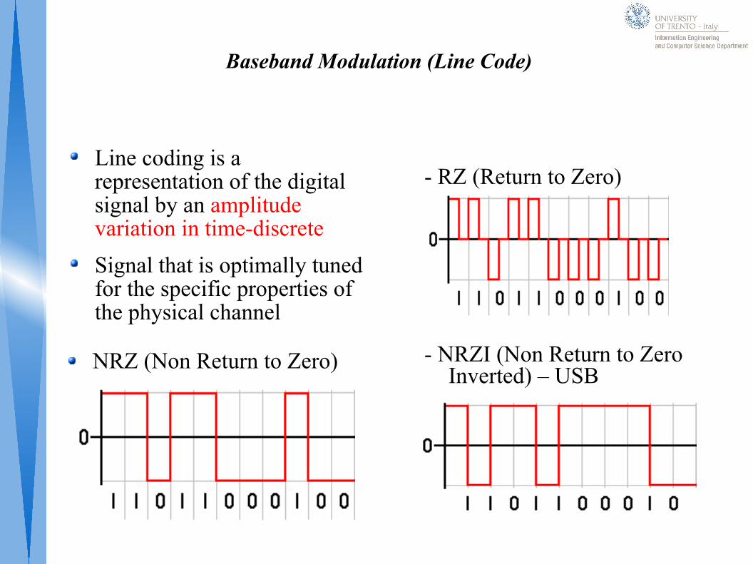
Line coding is a representation of the digital signal by an amplitude variation in time-discrete
Signal that is optimally tuned for the specific properties of the physical channel
- RZ (Return to Zero)
- NRZI (Non Return to Zero Inverted) – USB
NRZ (Non Return to Zero)
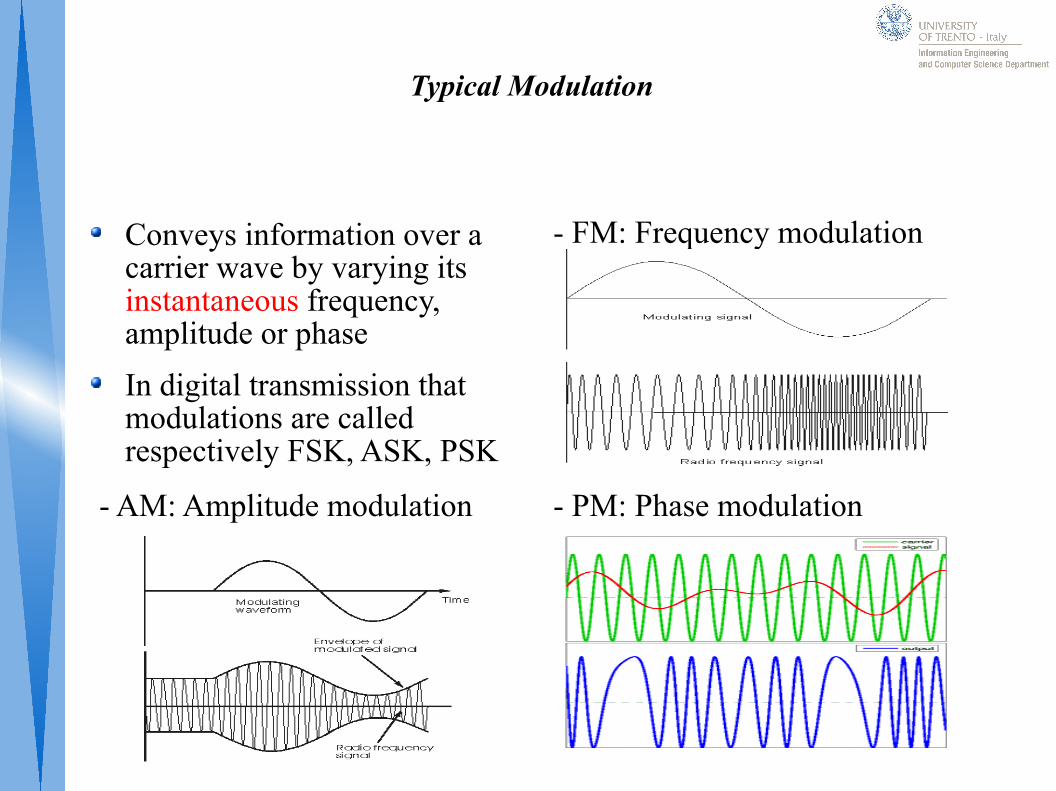
Typical Modulation
Conveys information over a carrier wave by varying its instantaneous frequency, amplitude or phase
In digital transmission that modulations are called respectively FSK, ASK, PSK
- FM: Frequency modulation
- PM: Phase modulation- AM: Amplitude modulation
Q-AM Quadrature Amplitude Modulation
Q-AM modulation permits to transmit symbols and not only a bit stream.
Data Bits are modulated as symbol
A Symbol is identified by:- Amplitude Value- Phase Value
This means that it is possible to transmit a lot of bits with a single symbol
In 16Q-AM (as in figure) each symbol transmitted conveys 4 data bits
OFDM
OFDM (Orthogonal Frequency Division Multiplexing) is a modulation used in our digital television to transmit and receive tv channels
OFDM is a multi carrier wave modulation, this means that uses a lot of carrier, each orthogonal with other
OFDM main properties:
- Splits information flow on multiple carriers
- Each carrier is modulated using QAM modulation
- In QAM modulation is used a low symbol rate
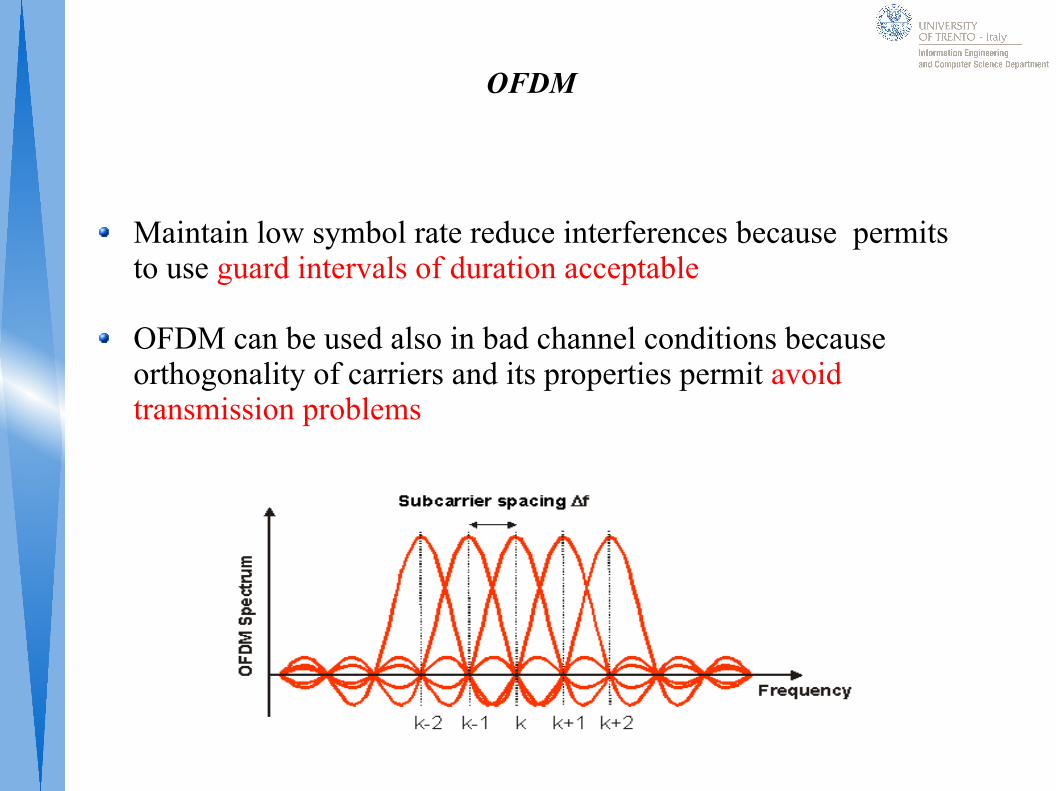
OFDM
Maintain low symbol rate reduce interferences because permits to use guard intervals of duration acceptable
OFDM can be used also in bad channel conditions because orthogonality of carriers and its properties permit avoid transmission problems
Chapter 5 - Channels
Channel
Channel: refers either a physical transmission medium such as a wire, or to a logical connection over a multiplexed medium such as a radio channel
A channel is used to convey an information signal from one or several transmitters to one or several receivers
Channel capacity: is the maximum quantity of information that can be reliably transmitted measured in:
- Bandwidth (Hz) - Data rate (bits / second)
Copper Wires
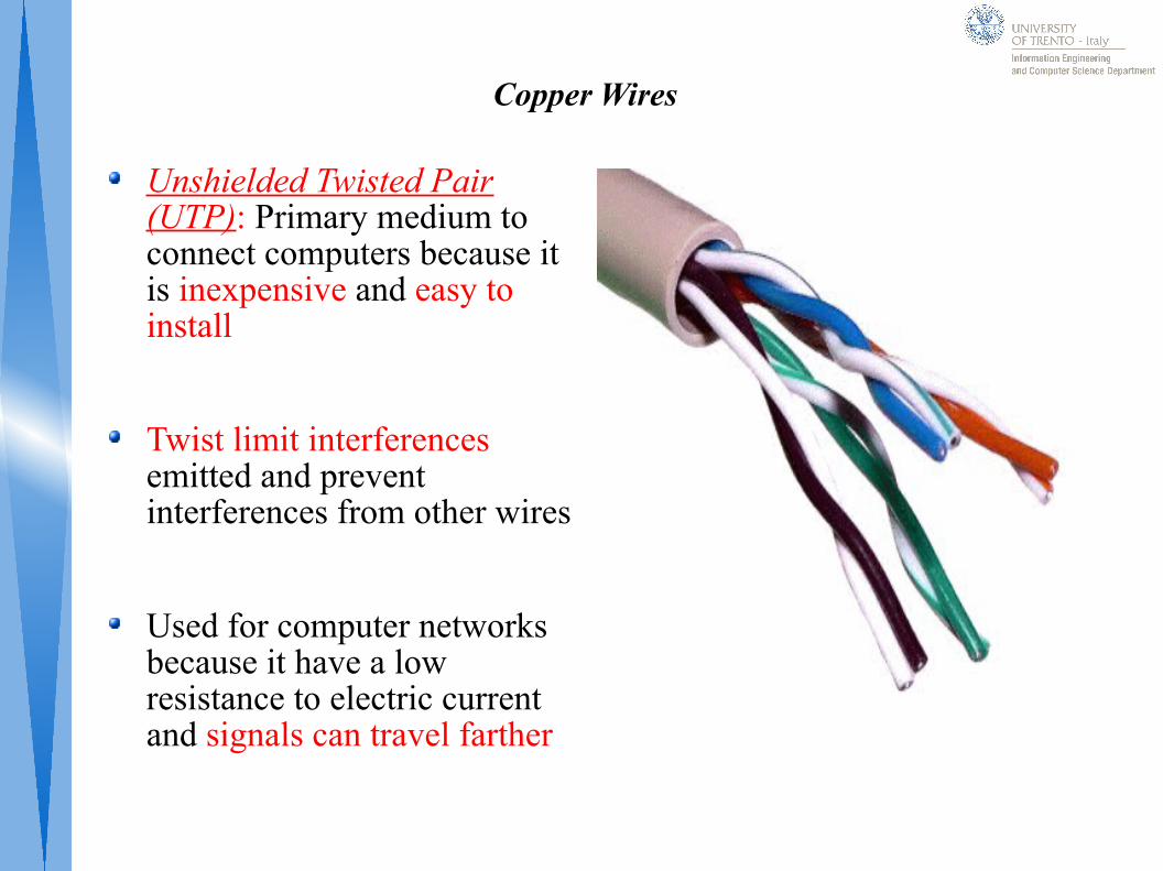
Unshielded Twisted Pair (UTP): Primary medium to connect computers because it is inexpensive and easy to install
Twist limit interferences emitted and prevent interferences from other wires
Used for computer networks because it have a low resistance to electric current and signals can travel farther
Copper Wires
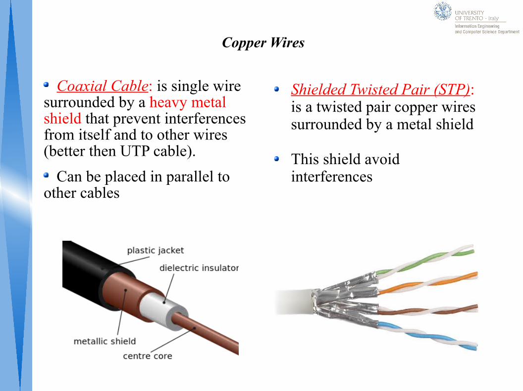
Coaxial Cable: is single wire surrounded by a heavy metal shield that prevent interferences from itself and to other wires (better then UTP cable).
Can be placed in parallel to other cables
Shielded Twisted Pair (STP): is a twisted pair copper wires surrounded by a metal shield
This shield avoid interferences
Glass Fiber
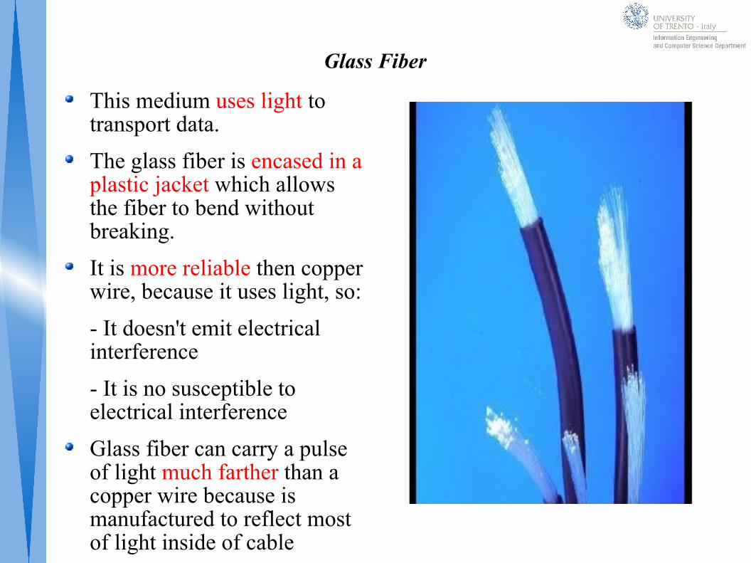
This medium uses light to transport data.
The glass fiber is encased in a plastic jacket which allows the fiber to bend without breaking.
It is more reliable then copper wire, because it uses light, so:
- It doesn't emit electrical interference
- It is no susceptible to electrical interference
Glass fiber can carry a pulse of light much farther than a copper wire because is manufactured to reflect most of light inside of cable
Radio - Wireless
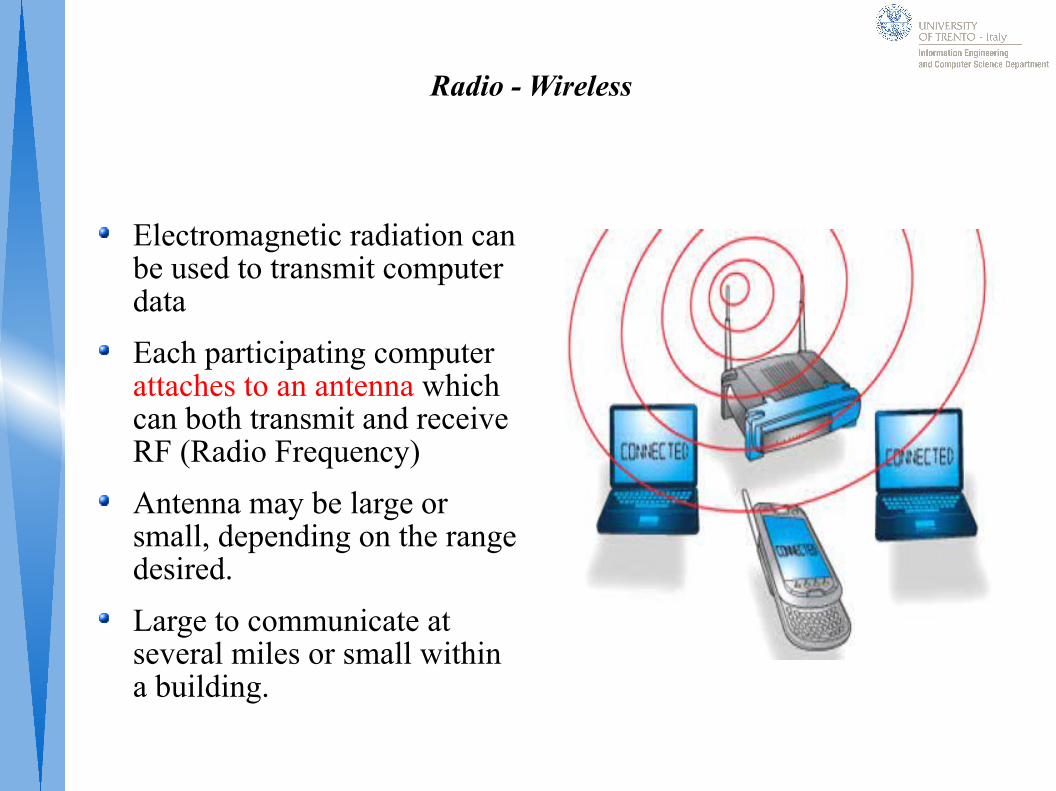
Electromagnetic radiation can be used to transmit computer data
Each participating computer attaches to an antenna which can both transmit and receive RF (Radio Frequency)
Antenna may be large or small, depending on the range desired.
Large to communicate at several miles or small within a building.
Satellite
Satellite contains a transponder that consist of a radio receiver and transmitter
Transponder accepts an incoming radio transmission, amplifies it, and re-transmits, amplified signal, back to the ground at a different angle than it arrived.
A single satellite contains multiple transponders that operate independently because place a satellite in orbit it is very expensive
Geosynchronous Satellite (GEO)
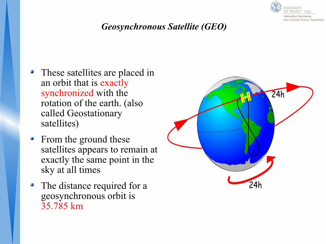
These satellites are placed in an orbit that is exactly synchronized with the rotation of the earth. (also called Geostationary satellites)
From the ground these satellites appears to remain at exactly the same point in the sky at all times
The distance required for a geosynchronous orbit is 35.785 km
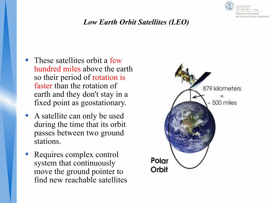
Low Earth Orbit Satellites (LEO)
These satellites orbit a few hundred miles above the earth so their period of rotation is faster than the rotation of earth and they don't stay in a fixed point as geostationary.
A satellite can only be used during the time that its orbit passes between two ground stations.
Requires complex control system that continuously move the ground pointer to find new reachable satellites
Summary
Signals
Transmission
Encoding
Hamming Codes and Example
CRC Codes
RS - Codes
Modulation
Channels
Thanks!
Rigato Lorenzo – Computer Science Student Email: [email protected]
Lo Cigno Renato – Advanced Networking Professor