Embed Size (px)
Citation preview
RESEARCH Open Access
Physical human-robot interaction of anactive pelvis orthosis: toward ergonomicassessment of wearable robotsNicolò d’Elia1,2*, Federica Vanetti2, Marco Cempini1, Guido Pasquini2, Andrea Parri1, Marco Rabuffetti3,Maurizio Ferrarin3, Raffaele Molino Lova2 and Nicola Vitiello1,2
Abstract
Background: In human-centered robotics, exoskeletons are becoming relevant for addressing needs in the healthcareand industrial domains. Owing to their close interaction with the user, the safety and ergonomics of these systems arecritical design features that require systematic evaluation methodologies. Proper transfer of mechanical power requiresoptimal tuning of the kinematic coupling between the robotic and anatomical joint rotation axes. We present themethods and results of an experimental evaluation of the physical interaction with an active pelvis orthosis (APO). Thisdevice was designed to effectively assist in hip flexion-extension during locomotion with a minimum impact on thephysiological human kinematics, owing to a set of passive degrees of freedom for self-alignment of the human androbotic hip flexion-extension axes.
Methods: Five healthy volunteers walked on a treadmill at different speeds without and with the APO under differentlevels of assistance. The user-APO physical interaction was evaluated in terms of: (i) the deviation of human lower-limbjoint kinematics when wearing the APO with respect to the physiological behavior (i.e., without the APO); (ii) relativedisplacements between the APO orthotic shells and the corresponding body segments; and (iii) the discrepancybetween the kinematics of the APO and the wearer’s hip joints.
Results: The results show: (i) negligible interference of the APO in human kinematics under all the experimentedconditions; (ii) small (i.e., < 1 cm) relative displacements between the APO cuffs and the corresponding body segments(called stability); and (iii) significant increment in the human-robot kinematics discrepancy at the hip flexion-extensionjoint associated with speed and assistance level increase.
Conclusions: APO mechanics and actuation have negligible interference in human locomotion. Human kinematics wasnot affected by the APO under all tested conditions. In addition, under all tested conditions, there was no relevant relativedisplacement between the orthotic cuffs and the corresponding anatomical segments. Hence, the physical human-robotcoupling is reliable. These facts prove that the adopted mechanical design of passive degrees of freedom allows aneffective human-robot kinematic coupling. We believe that this analysis may be useful for the definition of evaluationmetrics for the ergonomics assessment of wearable robots.
Keywords: Wearable robotics, Active pelvis orthosis, Ergonomics, Passive degrees of freedom, Series-elastic actuation
* Correspondence: [email protected] BioRobotics Institute, Scuola Superiore Sant’Anna, viale Rinaldo Piaggio,34, 56025 Pontedera, Pisa, Italy2Fondazione Don Carlo Gnocchi IRCCS, Florence, ItalyFull list of author information is available at the end of the article
© The Author(s). 2017 Open Access This article is distributed under the terms of the Creative Commons Attribution 4.0International License (http://creativecommons.org/licenses/by/4.0/), which permits unrestricted use, distribution, andreproduction in any medium, provided you give appropriate credit to the original author(s) and the source, provide a link tothe Creative Commons license, and indicate if changes were made. The Creative Commons Public Domain Dedication waiver(http://creativecommons.org/publicdomain/zero/1.0/) applies to the data made available in this article, unless otherwise stated.
d’Elia et al. Journal of NeuroEngineering and Rehabilitation (2017) 14:29 DOI 10.1186/s12984-017-0237-y
BackgroundIn the field of human-centered robotics, exoskeletonsare becoming relevant for addressing needs in thehealthcare and industrial domains [1, 2], both as toolsfor rehabilitation treatment and clinical assessment [3, 4]and for augmented reality applications (haptics [5] oraugmentation [6]). Despite the increasing interest andnumber of developed prototypes and commercial systems,the design of exoskeletons still has many open issues, suchas those related to the development of the physicalhuman-robot (HR) interface. Owing to their close inter-action with the user, safety and ergonomics are criticalfeatures that heavily influence the functionality and thedependability of a wearable robot (WR) [7]. In general,these devices are designed to generate and transfer mech-anical power to human joints: therefore, optimalkinematic coupling is required between the correspondinghuman and robot rotation axes [8].Misalignment between the human and robot joint axes
can cause undesired forces that overload human articu-lations, thus resulting in an uncomfortable or evenpainful interaction with the robot [9]. Undesired forcesoriginating from joint axis misalignments (JAxM) canalso lead the orthotic shells of the exoskeleton to slidealong the human limb segments, leading to unreliableassistive torque transmission [10] and possible skininflammation or even sores.Unfortunately, the achievement of adequate human-
robot joint axis alignment is not an easy condition to befulfilled for two main reasons. First, it is not possible toknow the exact location of the anatomical joint rotationaxis without complex imaging techniques. Second,human articulations are not ideal rotational or sphericalmechanical couplings; rather, they have more complexsubject-dependent geometries that make the rotationaxes fluctuate along the range of movement (ROM) [10].As a consequence of the above considerations, most
exoskeletons are provided with regulation mechanismsand/or passive degrees of freedom (pDoFs), in accord-ance with the guidelines proposed in [11]. In his work,Stienen and colleagues explained that it is possible tounload human articulations from undesired translationalforces by decoupling joint rotations and translations byadding a certain number of passive DoFs to exoskeletonjoints. Examples of WRs for both upper- and lower-limbassistance/rehabilitation equipped with passive DoFshave been reported in [11–14]. A more recent study alsointroduced a theoretical framework to identify theconstructive parameters of the chain of passive DoFsthat are necessary to cope with human flexion-extensionarticulations [7].However, the introduction of passive DoFs into the de-
sign of a WR is not free of drawbacks; the tradeoffbetween the degrees of laxity [15] and the system
complexity may affect the overall human-robot kinemat-ics coupling [7]. On the one hand, by increasing thedegree of laxity of the powered joints, there is a risk ofincreasing the overall inertia and friction of the movingparts. On the other hand, a lack of adequate laxity par-tially affects the human-robot joint axis self-alignmentand thus hinders the spontaneous movement of the user.As a consequence, in the development and design of anexoskeleton, the assessment of its kinematic compatibil-ity with user biomechanics is of paramount importance.Many exoskeletons constitute the current state of the
art; the variety of mechatronics designs, control systems,and human-machine interfaces are due to differences inthe targeted users and expected usage. An extensivereview of WRs, their design methodologies, and controlstrategies can be found in [16–18].A category of powered WRs that is gaining an increas-
ing level of attention is that of exoskeletons addressingthe needs of people with mild gait disturbances (e.g., gaitpost-stroke hemiparesis, unilateral lower-limb amputa-tion, senile gait, etc.), who may benefit from the use oflight-weight assistive WRs to recover more stable,efficient, and independent locomotion [17, 19–21].At The BioRobotics Institute (Scuola Superiore
Sant’Anna, Pisa, Italy), we have recently developed a revisedversion of the active pelvis orthosis (APO) presented in[22], a wearable exoskeleton aimed at improving the gaitenergy efficiency of users affected by mild impairmentsthrough the assistance of hip flexion-extension (f/e) [23].The main advancement of the new device over the previousversion is the introduction of a chain of passive DoFs thatallows the human f/e axis to align with that of the robotand simultaneously gives the user free hip abduction/ad-duction (a/a) and internal/external (i/e) rotations. The APOis interfaced with the wearer through tailored thermoplasticorthotic shells (namely, cuffs) to ensure maximum comfort.The adopted design criterion is in line with the
approaches proposed by several authors [7, 10, 11] forthe development of exoskeletons that interact smoothlywith the wearer. Nevertheless, to the best of our know-ledge, no ergonomics evaluation methodology has beenproposed in the literature and no clear definition of WRergonomics has been given. Hereafter, we refer toergonomics as the capability (of a WR) to smoothlyinteract with the user along the whole work space by“optimizing human well-being and overall systemperformance” [24] and without hindering natural kinematicsor causing discomfort and/or injury.The direct evaluation of ergonomics from ultimate
determinants, such as comfort and risk of injury, may beperformed only after long-term use. For this reason, thepossibility to define the “level of ergonomics” from easilyobtainable indirect measures that are related toergonomics is attractive.
d’Elia et al. Journal of NeuroEngineering and Rehabilitation (2017) 14:29 Page 2 of 14
In this work, we carried out an experimental validationwith healthy volunteers with the objective of assessingthe quality of the user-APO physical interaction withparticular reference to the chain of passive DoFs and therelative shifts between the APO frame and the humanbody at the physical interfacing areas. Using this specificdevice as an example, we discuss the specific design of aWR and propose a set of indicators that could berelevant for its evaluation in terms of ergonomics.First, we analyzed the alteration of lower-limb joint
kinematics by comparing the condition in which userswalked without wearing the APO and all experimentalconditions when they wore it. Human kinematics wasrecorded by means of an optoelectronic motion capturesystem. Secondly, we analyzed the stability of thephysical interaction between the users and the APO bymeasuring: (i) the displacements between the APOorthotic cuffs and the wearer’s corresponding bodysegments, and (ii) the kinematic discrepancy betweenthe APO and the wearer's hip f/e joint angle.Besides the ease of measurement, the following
hypotheses form the rationale behind the choice of thesevariables: (i) deviation from natural kinematics is recog-nized as a negative effect on the wearer; (ii) relativedisplacements at the HR interface may cause skin irrita-tions or sores and therefore discomfort or injuries; (iii)HR kinematic discrepancy together with relativedisplacements at the interface may reveal possible JAxM,which are the cause of residual forces onto articulationsand possibly pain or injuries after prolonged use.We carried out this study being aware that: (i) opto-
electronic systems have been widely used to measurehuman gait kinematics [25], also during orthosis-assisted
locomotion [26, 27], and (ii) the feasibility of measuringdisplacements in the order of millimeters (in the range3.2–6.7 mm) using a video-based motion capture system,such as that used in the present application, has beenalready demonstrated [28, 29].
MethodsParticipantsFive healthy adults (74.4 ± 6.8 kg, 1.73 ± 0.07 m, 29.2 ±6.3 years old) were enrolled for the study. All partici-pants signed an informed consent before starting theexperimental sessions. The research procedures wereconducted at the premises of Fondazione Don CarloGnocchi (Firenze, Italy) in accordance with the Dec-laration of Helsinki, after the approval of the localEthical Committee.
Active pelvis orthosisThe APO is a bilateral powered exoskeleton, and it isconstituted of three main subsystems: the mechanicalstructure, the actuation units, and the control system. Inthe following, we provide a description that summarizesits main features.The mechanical structure of the APO is symmetrical
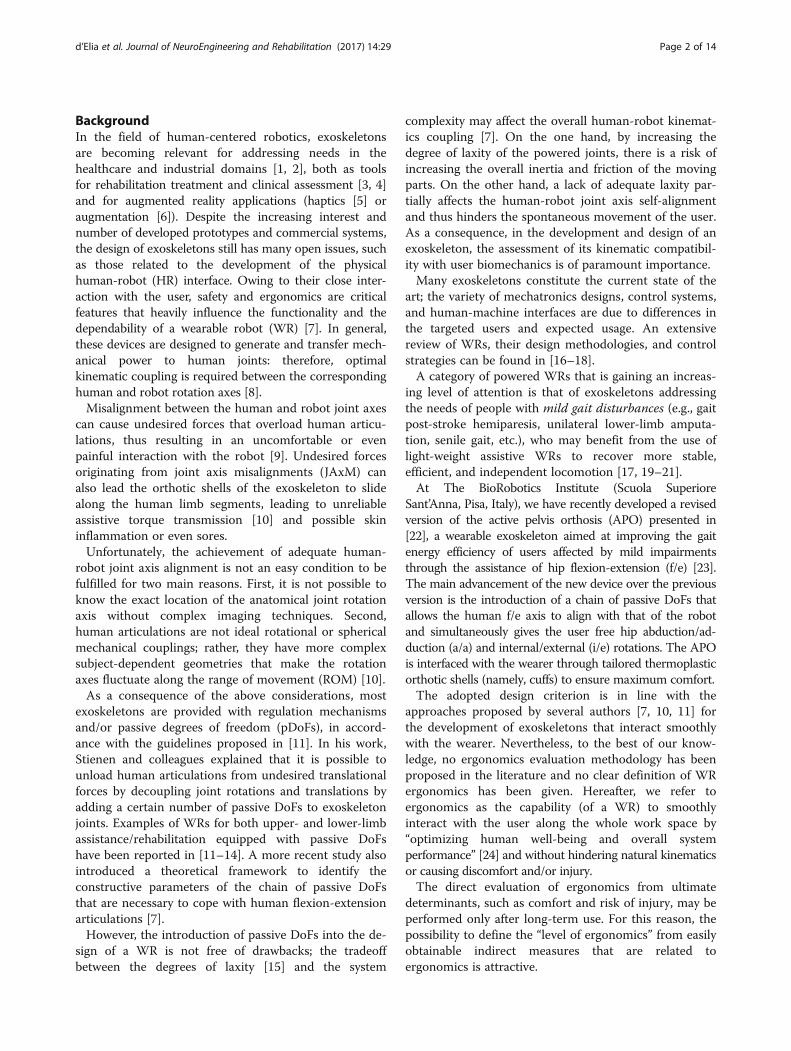
with respect to the sagittal plane (Fig. 1). Each side ofthe robot is composed of two main subsystems, namely,the chain of passive DoFs and the transmission meansthat transfer the assistive torque from the actuation unitto the human hip articulation.Each chain of passive DoFs originates from a main
posterior carbon fiber plate (i.e., the frame of the chainof passive DoFs), which connects the exoskeleton to thewearer’s trunk by means of an orthotic cuff. Another
Fig. 1 a Human skeleton covered by soft tissues. b Human body with wearable robotic chain schematic: (1) passive translational DoF, (2) abduction/adduction rotation passive DoF, (3) internal/external rotation passive DoF, (4) rotation passive DoF, (a) pelvis cuff, (d) internal/external rotation joint, (e)abduction/adduction joint, (f) flexion/extension joint. c Human body coupled with exoskeleton: b carbon-fiber plate, c sliding carbon-fiber plate, g lateralextensible arm, h thigh linkage, i thigh cuff. For the sake of clarity, only the right part of the bilateral APO is represented
d’Elia et al. Journal of NeuroEngineering and Rehabilitation (2017) 14:29 Page 3 of 14
carbon-fiber plate can slide horizontally against theframe by means of a passive translational DoF (axisnumber 1 in Fig. 1). The sliding plate houses two passiverotational DoFs, whose axes of rotation (namely, axesnumber 2 and 3 in Fig. 1) are orthogonal and cross eachother at point P. Thanks to the combined action of thetranslational passive DoF, the rotation axis number 2can be aligned with the human hip a/a axis. The rangeof motion of axis number 2, and, consequently, that ofthe user’s a/a, is restricted to −15° to +20° via mechan-ical end stops. The concomitant movement of the trans-lational passive DoF and that of axis number 3 allow theuser to also have a free hip i/e. The ROM of axisnumber 3 is restricted to –10° to +10° by mechanicalend stops. This kinematic chain of passive DoFsconnects the main carbon fiber plate to a lateral arm,also made of carbon fiber. The distance between the leftand right lateral arms on the frontal plane can bemanually adjusted to fit the width of the wearer’s pelvis.Each lateral arm is made of two telescopic shells thatcan slide against each other in order to maximally alignthe human and robot f/e axes in the sagittal plane bymanually tuning their lengths. A thigh linkage rotatesaround the f/e axis and couples with the wearer’s thighvia an orthotic shell. Finally, an additional rotationalDoF is inserted between each link and the cuff (axisnumber 4 in Fig. 1); this allows the alignment of the cuffand thigh longitudinal axes, thus providing considerablestability during movement. The APO kinematic chaindesign is patent pending [30].The transmission system connects the actuation unit
placed on the rear part of the lateral arm to a drivenpulley placed coaxially with the hip f/e axis by means ofa steel cable (U8191517, Carl Stahl®GmbH, Suessen,Germany) in a capstan configuration. The stiffness ofthe cable is 250 N/mm, equivalent to a torsional stiffnessat the hip joint of 756 Nm/rad. The rotation axis of theactuation unit is parallel to the hip f/e axis.Each actuation unit is a series elastic actuator (SEA).
Each SEA is composed of a 70 W DC motor (EC60,Maxon Motor®, Sachseln, Switzerland), a 100:1 harmonicdrive (CPL-14A-100-2A, Harmonic Drive®, Limburg,Germany), and a custom torsional spring (patent pend-ing) having a stiffness of 100 Nm/rad. Two absolute 17-bit Rotary Electric Encoder™ units (DS-37 and DS-25Netzer Precision Motion Sensors Ltd, Misgav, Israel)measure the spring deformation and the actual hip jointangle, respectively.The control system has a hierarchical structure made
of a low- and a high-level layer. For the control system,we adopted the same control architecture as thatdescribed in [22]; hereafter, its main features arerecapped for the sake of clarity. The low-level layer is aclosed-loop torque control. The controller is a 2-pole-2-
zero compensator. The closed-loop compensator allowsfor a relatively high closed-loop bandwidth (namely,15.5 Hz) and low joint residual parasitic stiffness (lowerthan 1 Nm/rad in the typical frequency range of walk-ing). The high-level assistive control aims at computinga desired assistive torque profile during the stride foreach of the two powered hip joints. It is based on themodel-free algorithm presented in [31]. It relies onadaptive oscillators, mathematical tools [32] that—whencoupled with a kernel-based non-linear filter—can track,estimate, and predict quasi-periodic signals (e.g., hipangles during gait) with zero-delay. Hence, duringground-level walking tasks, it is possible to determinethe phase φ, frequency, and envelope of each hip jointangle and to reliably predict the joint angle during thestride period thanks to an adjustable phase shift Δφ(Δφ = 0.628 rad in this work). The assistive reference
torque is provided by: τdes ¼ Kv⋅ θ̂j φþ Δφð Þ−θ̂ j φð Þh i
,
where Kv [Nm/rad] is an adjustable virtual stiffness andbθj φð Þ and bθj φþ Δφð Þ are the hip joint angle estimateand its predicted future value, respectively. This meansthat thanks to the virtual stiffness, we can attract the hip
f/e angle from the current position θ̂j φð Þ to the future θ̂jφþ Δφð Þ as a result of the application of a torque τdes.In this experiment, the parameters of the assistive con-troller were set according to [31].
Experimental protocolAll volunteers walked barefoot on a treadmill at threedifferent speeds (slow, normal, and fast, named V1, V2,and V3, respectively) and under five modalities, namely:(i) without wearing the APO mechanics, but with thepelvis orthotic cuff (natural walking, NW); (ii) wearingthe APO in the zero-torque control mode (transparentmode, TM); (iii)–(v) assistive mode with three differentlevels of assistance (low, moderate, and high assistive modes,named AM1, AM2, and AM3, respectively). The velocity V2was selected according to the principle of dynamic similar-ities [33] and was thus calculated as V2 ¼ ffiffiffiffiffiffiffiffiffiffiffiffiffi
Fr⋅g⋅Lp
, whereFr is the Froude number, g is the gravity constant, and L isthe leg length (measured from the greater trochanterprominence to the lateral malleolus). In this experi-ment, Fr = 0.1. V1 and V3 were selected to be equalto V2 ± 0.25 V2. Each subject walked in all conditions(in the order: NW, TM, AM1, AM2, and AM3) at alldifferent speeds (in the order: V1, V2, and V3). Eachtrial consisted of 20 strides.The desired assistance level was set according to the
following methodology. During a familiarization session,each volunteer was requested to walk at V3 while theexperimenter progressively increased the value of Kv.The value of Kv for AM3 was that corresponding to the
d’Elia et al. Journal of NeuroEngineering and Rehabilitation (2017) 14:29 Page 4 of 14
highest level of assistance that the subject considered ascomfortable. In fact, all subjects reported discomfort forhigh values of Kv. When the peak torque—normalized tobody weight—exceeded an across-subjects average valueof 0.14 Nm/kg, the human and robotic hip joint kine-matics difference increased, thus resulting in an assistiveaction that is not compliant with human biomechanics.We will further discuss this issue in the discussionsession. Once the Kv upper limit was identified, it wasscaled down by 33 and 66% for the AM2 and AM1conditions, respectively.Owing to the APO modular architecture, it was
possible to wear only the pelvis cuff in NW. In allother assisted conditions, including TM, thigh cuffswere also worn.
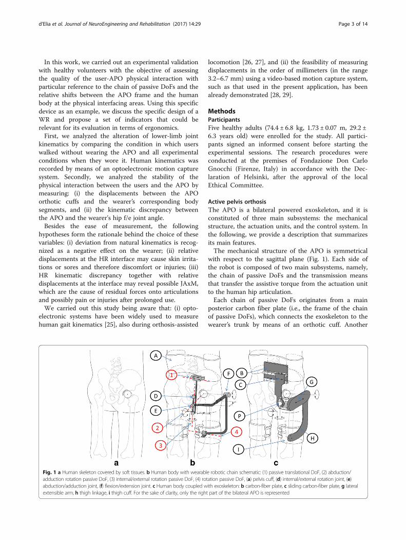
Data acquisition and processingThe APO actual hip joint angle and torque were mea-sured by using the information from the encoders.Lower-limb kinematics and the movement between theorthotic cuffs and the corresponding body segmentswere measured by means of an optoelectronic system(SmartD, BTS, Milan, Italy) detecting spherical passivemarkers placed on specific points on the robot and user.Standard software (Smart Tracker, BTS, Milan, Italy)was used to compute the 3D coordinates of the markers.Ad-hoc post-processing was performed in the MATLABenvironment (MathWorks, Natick, MA, USA). Humankinematics was calculated according to an adaptedLAMB model [34] (see Fig. 2), in which the requiredposterior superior iliac spine landmark, hidden by theexoskeleton, was reconstructed through a marker placedon top of a pelvis-anchored stick. All acquired data weresegmented according to heel strikes and resampled from0 to 100% of the stride cycle. The heel strikes weredetected with a dedicated algorithm that processes the3D coordinates of feet markers.From the collected data, we computed the following
variables, which provided a quantitative assessment of thelevel of ergonomics: (i) the root mean square (RMS) of thedifference of the hip, knee, and ankle f/e angle—measuredby the motion capture system—between the NW andTM/AM conditions; we named these variables ‘human hipangle deviation’ (H-HAD), ‘human knee angle deviation’(H-KAD), and ‘human ankle angle deviation’ (H-AAD),respectively; (ii) the RMS of the difference between theAPO hip f/e angle, recorded by the joint encoder, and theanatomical hip f/e angle, computed through the motioncapture system; we named this variable ‘human-robot hipangle deviation’ (HR-HAD); (iii) the standard deviation(SD) of the relative displacements between the markersplaced on the orthotic cuffs of the APO and those placedon their corresponding body segments; we named this setof variables ‘physical human-robot interface displacement’
(pHR-ID); (iv) the human joints’ ROM in the sagittal plane(hip, knee, and ankle) and in the frontal plane (only at thehip); and (v) spatio-temporal parameters (i.e., step length,stance time, and cadence).In the case of the pHR-ID calculation, we used the
SD instead of the RMS because it is more adequatefor measuring the relative displacements of two pointsin space, without considering the constant offset be-tween them.The reference value used to evaluate H-HAD, H-KAD,
and H-AAD in all walking conditions was the averageintra-subject variability, defined as the among-subjectsaverage of intra-subject variability. The intra-subjectvariability, calculated in each walking condition for onesubject, is here defined as the average SD in a strideperiod. Hence, the intra-subject variability quantifies thenatural differences of the f/e angles for one subject,while the average intra-subject variability captures the
Fig. 2 Adapted LAMB model marker setup. Posterior superior iliacspine landmark, hidden by the exoskeleton, was reconstructed through amarker placed on top of a pelvis-anchored stick (encircled in red). Redarrows shows which marker are used to calculate body-cuffrelative displacements
d’Elia et al. Journal of NeuroEngineering and Rehabilitation (2017) 14:29 Page 5 of 14
mean of these natural kinematic differences consideringall subjects.The relative displacement between markers placed on
the same rigid body, namely, the pelvis cuff of the APOduring walking, averaged over all conditions, was takenas the noise level of the experimental setup (2.3 ±0.8 mm).Since we verified that no significant left/right differ-
ences (p < 0.05) were present in all data, in thefollowing, only the right-side data are presented.In order to evaluate significant differences due to the
effects of speed and the walking modality, a two-wayANOVA (p < 0.05) with the Fisher LSD post-hoccomparison was performed.
ResultsAll volunteers completed the experimental tests suc-cessfully and wore the APO in the TM and AMswithout reporting discomfort. All subjects showed anaverage pelvis anteversion of 10 ± 1° when wearing theAPO with respect to not wearing it (in accordancewith [35]).
Spatio-temporal parametersTable 1 reports the spatio-temporal parameters fordifferent trials. When considering speeds, the stancetime shows a negative trend associated with speedincrease, while cadence shows a positive trend; con-versely, none of the spatio-temporal parameters showany trend associated with the assistance level. Allspatio-temporal parameters, except step length, showsignificant differences due to speed increase. Whencomparing natural walking with the TM/AMs, allspatio-temporal parameters except the stance timeshow no significant differences. In particular, theaverage stance time in AM2 is slightly larger than inNW. When comparing walking conditions in whichthe exoskeleton was worn, no statistically relevantdifferences are found, except for the stance time,which shows a difference between TM and AM2.
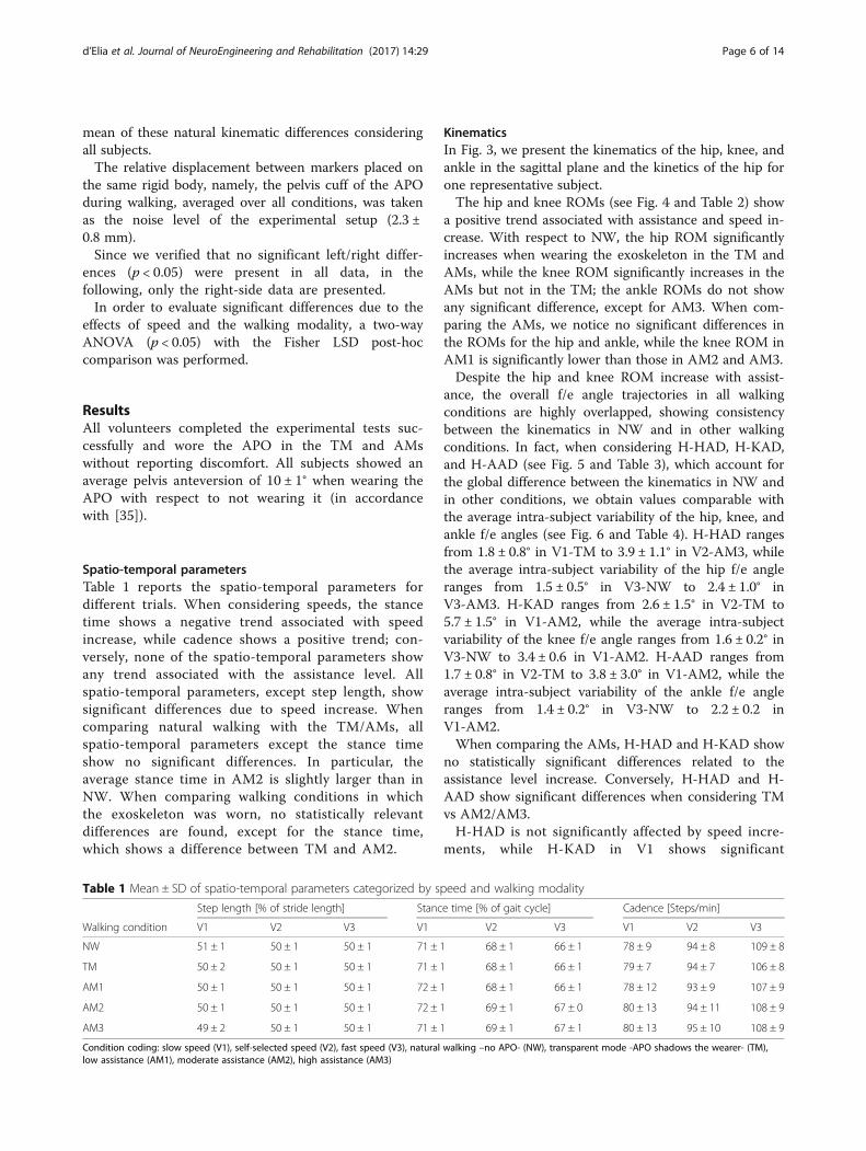
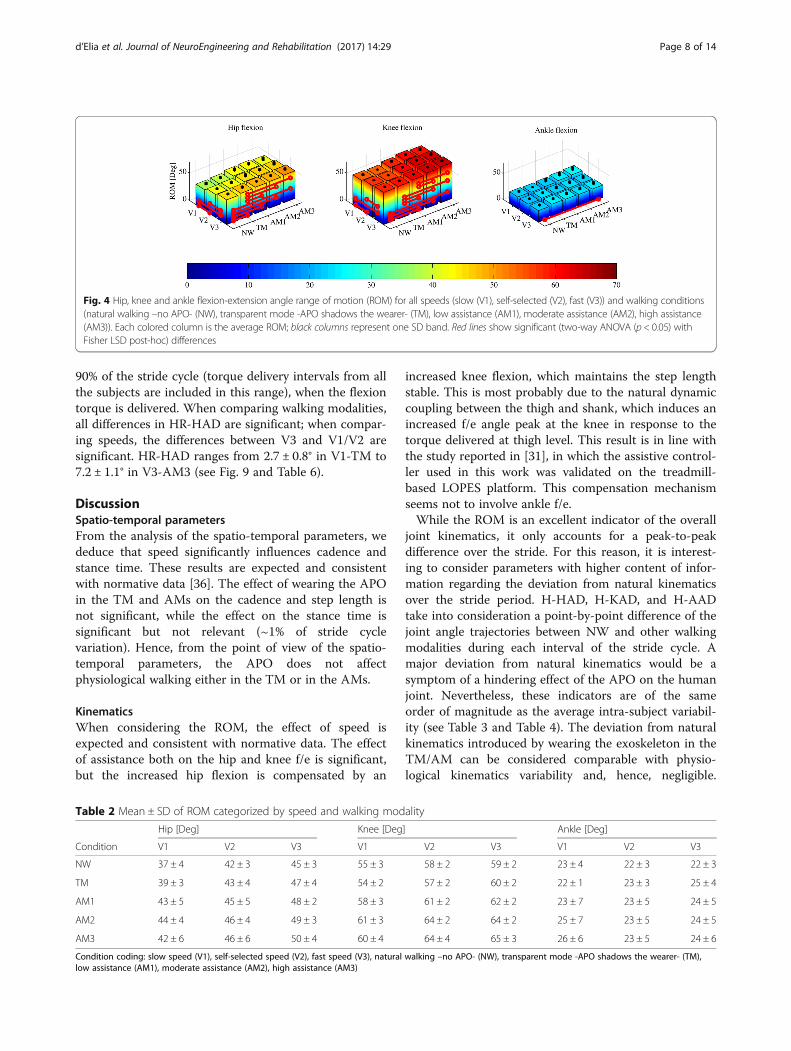
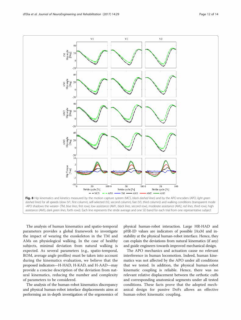
KinematicsIn Fig. 3, we present the kinematics of the hip, knee, andankle in the sagittal plane and the kinetics of the hip forone representative subject.The hip and knee ROMs (see Fig. 4 and Table 2) show
a positive trend associated with assistance and speed in-crease. With respect to NW, the hip ROM significantlyincreases when wearing the exoskeleton in the TM andAMs, while the knee ROM significantly increases in theAMs but not in the TM; the ankle ROMs do not showany significant difference, except for AM3. When com-paring the AMs, we notice no significant differences inthe ROMs for the hip and ankle, while the knee ROM inAM1 is significantly lower than those in AM2 and AM3.Despite the hip and knee ROM increase with assist-
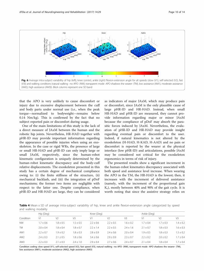
ance, the overall f/e angle trajectories in all walkingconditions are highly overlapped, showing consistencybetween the kinematics in NW and in other walkingconditions. In fact, when considering H-HAD, H-KAD,and H-AAD (see Fig. 5 and Table 3), which account forthe global difference between the kinematics in NW andin other conditions, we obtain values comparable withthe average intra-subject variability of the hip, knee, andankle f/e angles (see Fig. 6 and Table 4). H-HAD rangesfrom 1.8 ± 0.8° in V1-TM to 3.9 ± 1.1° in V2-AM3, whilethe average intra-subject variability of the hip f/e angleranges from 1.5 ± 0.5° in V3-NW to 2.4 ± 1.0° inV3-AM3. H-KAD ranges from 2.6 ± 1.5° in V2-TM to5.7 ± 1.5° in V1-AM2, while the average intra-subjectvariability of the knee f/e angle ranges from 1.6 ± 0.2° inV3-NW to 3.4 ± 0.6 in V1-AM2. H-AAD ranges from1.7 ± 0.8° in V2-TM to 3.8 ± 3.0° in V1-AM2, while theaverage intra-subject variability of the ankle f/e angleranges from 1.4 ± 0.2° in V3-NW to 2.2 ± 0.2 inV1-AM2.When comparing the AMs, H-HAD and H-KAD show
no statistically significant differences related to theassistance level increase. Conversely, H-HAD and H-AAD show significant differences when considering TMvs AM2/AM3.H-HAD is not significantly affected by speed incre-
ments, while H-KAD in V1 shows significant
Table 1 Mean ± SD of spatio-temporal parameters categorized by speed and walking modality
Step length [% of stride length] Stance time [% of gait cycle] Cadence [Steps/min]
Walking condition V1 V2 V3 V1 V2 V3 V1 V2 V3
NW 51 ± 1 50 ± 1 50 ± 1 71 ± 1 68 ± 1 66 ± 1 78 ± 9 94 ± 8 109 ± 8
TM 50 ± 2 50 ± 1 50 ± 1 71 ± 1 68 ± 1 66 ± 1 79 ± 7 94 ± 7 106 ± 8
AM1 50 ± 1 50 ± 1 50 ± 1 72 ± 1 68 ± 1 66 ± 1 78 ± 12 93 ± 9 107 ± 9
AM2 50 ± 1 50 ± 1 50 ± 1 72 ± 1 69 ± 1 67 ± 0 80 ± 13 94 ± 11 108 ± 9
AM3 49 ± 2 50 ± 1 50 ± 1 71 ± 1 69 ± 1 67 ± 1 80 ± 13 95 ± 10 108 ± 9
Condition coding: slow speed (V1), self-selected speed (V2), fast speed (V3), natural walking –no APO- (NW), transparent mode -APO shadows the wearer- (TM),low assistance (AM1), moderate assistance (AM2), high assistance (AM3)
d’Elia et al. Journal of NeuroEngineering and Rehabilitation (2017) 14:29 Page 6 of 14
differences from V2 and V3; H-AAD in V1 is signifi-cantly different from V3.
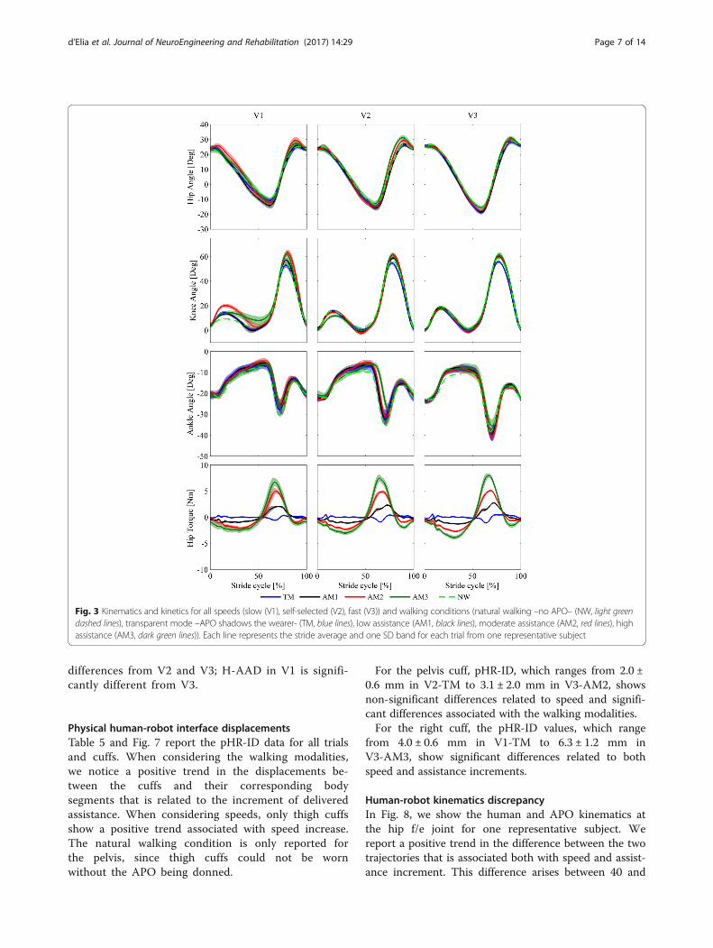
Physical human-robot interface displacementsTable 5 and Fig. 7 report the pHR-ID data for all trialsand cuffs. When considering the walking modalities,we notice a positive trend in the displacements be-tween the cuffs and their corresponding bodysegments that is related to the increment of deliveredassistance. When considering speeds, only thigh cuffsshow a positive trend associated with speed increase.The natural walking condition is only reported forthe pelvis, since thigh cuffs could not be wornwithout the APO being donned.
For the pelvis cuff, pHR-ID, which ranges from 2.0 ±0.6 mm in V2-TM to 3.1 ± 2.0 mm in V3-AM2, showsnon-significant differences related to speed and signifi-cant differences associated with the walking modalities.For the right cuff, the pHR-ID values, which range
from 4.0 ± 0.6 mm in V1-TM to 6.3 ± 1.2 mm inV3-AM3, show significant differences related to bothspeed and assistance increments.
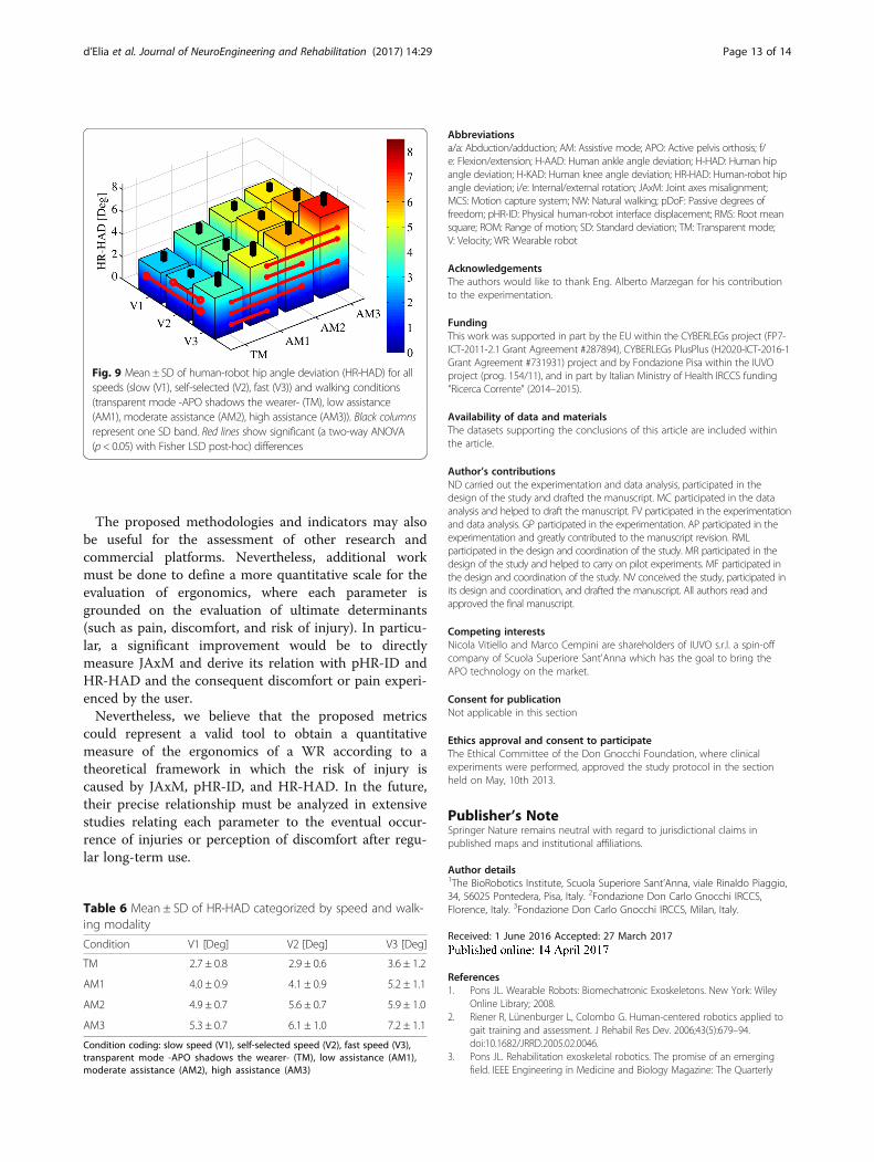
Human-robot kinematics discrepancyIn Fig. 8, we show the human and APO kinematics atthe hip f/e joint for one representative subject. Wereport a positive trend in the difference between the twotrajectories that is associated both with speed and assist-ance increment. This difference arises between 40 and
Fig. 3 Kinematics and kinetics for all speeds (slow (V1), self-selected (V2), fast (V3)) and walking conditions (natural walking –no APO– (NW, light greendashed lines), transparent mode –APO shadows the wearer- (TM, blue lines), low assistance (AM1, black lines), moderate assistance (AM2, red lines), highassistance (AM3, dark green lines)). Each line represents the stride average and one SD band for each trial from one representative subject
d’Elia et al. Journal of NeuroEngineering and Rehabilitation (2017) 14:29 Page 7 of 14
90% of the stride cycle (torque delivery intervals from allthe subjects are included in this range), when the flexiontorque is delivered. When comparing walking modalities,all differences in HR-HAD are significant; when compar-ing speeds, the differences between V3 and V1/V2 aresignificant. HR-HAD ranges from 2.7 ± 0.8° in V1-TM to7.2 ± 1.1° in V3-AM3 (see Fig. 9 and Table 6).
DiscussionSpatio-temporal parametersFrom the analysis of the spatio-temporal parameters, wededuce that speed significantly influences cadence andstance time. These results are expected and consistentwith normative data [36]. The effect of wearing the APOin the TM and AMs on the cadence and step length isnot significant, while the effect on the stance time issignificant but not relevant (~1% of stride cyclevariation). Hence, from the point of view of the spatio-temporal parameters, the APO does not affectphysiological walking either in the TM or in the AMs.
KinematicsWhen considering the ROM, the effect of speed isexpected and consistent with normative data. The effectof assistance both on the hip and knee f/e is significant,but the increased hip flexion is compensated by an
increased knee flexion, which maintains the step lengthstable. This is most probably due to the natural dynamiccoupling between the thigh and shank, which induces anincreased f/e angle peak at the knee in response to thetorque delivered at thigh level. This result is in line withthe study reported in [31], in which the assistive control-ler used in this work was validated on the treadmill-based LOPES platform. This compensation mechanismseems not to involve ankle f/e.While the ROM is an excellent indicator of the overall
joint kinematics, it only accounts for a peak-to-peakdifference over the stride. For this reason, it is interest-ing to consider parameters with higher content of infor-mation regarding the deviation from natural kinematicsover the stride period. H-HAD, H-KAD, and H-AADtake into consideration a point-by-point difference of thejoint angle trajectories between NW and other walkingmodalities during each interval of the stride cycle. Amajor deviation from natural kinematics would be asymptom of a hindering effect of the APO on the humanjoint. Nevertheless, these indicators are of the sameorder of magnitude as the average intra-subject variabil-ity (see Table 3 and Table 4). The deviation from naturalkinematics introduced by wearing the exoskeleton in theTM/AM can be considered comparable with physio-logical kinematics variability and, hence, negligible.
Fig. 4 Hip, knee and ankle flexion-extension angle range of motion (ROM) for all speeds (slow (V1), self-selected (V2), fast (V3)) and walking conditions(natural walking –no APO- (NW), transparent mode -APO shadows the wearer- (TM), low assistance (AM1), moderate assistance (AM2), high assistance(AM3)). Each colored column is the average ROM; black columns represent one SD band. Red lines show significant (two-way ANOVA (p < 0.05) withFisher LSD post-hoc) differences
Table 2 Mean ± SD of ROM categorized by speed and walking modality
Hip [Deg] Knee [Deg] Ankle [Deg]
Condition V1 V2 V3 V1 V2 V3 V1 V2 V3
NW 37 ± 4 42 ± 3 45 ± 3 55 ± 3 58 ± 2 59 ± 2 23 ± 4 22 ± 3 22 ± 3
TM 39 ± 3 43 ± 4 47 ± 4 54 ± 2 57 ± 2 60 ± 2 22 ± 1 23 ± 3 25 ± 4
AM1 43 ± 5 45 ± 5 48 ± 2 58 ± 3 61 ± 2 62 ± 2 23 ± 7 23 ± 5 24 ± 5
AM2 44 ± 4 46 ± 4 49 ± 3 61 ± 3 64 ± 2 64 ± 2 25 ± 7 23 ± 5 24 ± 5
AM3 42 ± 6 46 ± 6 50 ± 4 60 ± 4 64 ± 4 65 ± 3 26 ± 6 23 ± 5 24 ± 6
Condition coding: slow speed (V1), self-selected speed (V2), fast speed (V3), natural walking –no APO- (NW), transparent mode -APO shadows the wearer- (TM),low assistance (AM1), moderate assistance (AM2), high assistance (AM3)
d’Elia et al. Journal of NeuroEngineering and Rehabilitation (2017) 14:29 Page 8 of 14
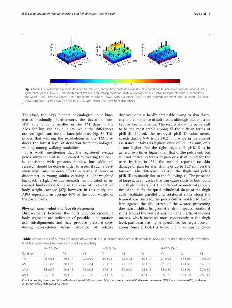
Therefore, the APO hinders physiological joint kine-matics minimally. Furthermore, the deviation fromNW kinematics is smaller in the TM than in theAMs for hip and ankle joints, while the differencesare not significant for the knee joint (see Fig. 5). Thisproves that wearing the exoskeleton in the TM pro-duces the lowest level of deviation from physiologicalwalking among walking modalities.It is worth mentioning that the registered average
pelvis anteversion of 10 ± 1° caused by wearing the APOis consistent with previous studies, but additionalresearch should be done in order to assess if such a devi-ation may cause noxious effects in terms of injury ordiscomfort in young adults carrying a light-weightedbackpack (8 kg). Previous research has indicated an in-creased lumbosacral force in the case of 15%–20% ofbody weight carriage [37]; however, in this study, theAPO represents in average 10% of the body weight ofthe participants.
Physical human-robot interface displacementsDisplacements between the cuffs and correspondingbody segments are indicators of possible joint rotationaxis misalignments and may produce pressure soresduring exoskeleton usage. Absence of relative
displacements is hardly obtainable owing to skin elasti-city and compliance of soft tissue, although they must bekept as low as possible. The results show the pelvis cuffto be the most stable among all the cuffs in terms ofpHR-ID. Indeed, the averaged pHR-ID value acrossspeeds during NW is 2.2 ± 0.2 mm, while in the case ofassistance, it takes its highest value of 3.2 ± 2.2 mm, only1 mm higher. For the right thigh cuff, pHR-ID is ingeneral two times higher than that of the pelvis cuff butstill not critical in terms of pain or risk of injury for theuser. In fact, in [38], the authors reported no skindamage or pain for skin strains of up to 11.7 mm on theforearm. The difference between the thigh and pelvispHR-IDs is mainly due to the following. (i) The presenceof large active muscles that can cause shifts of both cuffsand thigh markers. (ii) The different geometrical proper-ties of the cuffs; the quasi-cylindrical shape of the thighcuffs facilitates parallel and rotational shifts along thefemoral axis. Instead, the pelvis cuff is molded to firmlylean against the iliac crests of the wearer, preventingdownward shifts. Its geometry also impedes rotationalshifts around the vertical axis. (iii) The inertia of movingmasses, which increases more consistently at the thighlevel, particularly at higher speeds, i.e., for larger acceler-ations. Since pHR-ID is below 1 cm, we can conclude
Table 3 Mean ± SD of human hip angle deviation (H-HAD), human knee angle deviation (H-KAD) and human ankle angle deviation(H-AAD) categorized by speed and walking modality
H-HAD [Deg] H-KAD [Deg] H-AAD [Deg]
Condition V1 V2 V3 V1 V2 V3 V1 V2 V3
TM 1.8 ± 0.8 2.0 ± 1.1 2.9 ± 0.9 3.9 ± 2.6 2.6 ± 1.5 3.0 ± 1.7 2.1 ± 0.6 1.7 ± 0.8 1.9 ± 0.7
AM1 3.2 ± 0.6 2.8 ± 1.1 2.1 ± 0.4 5.1 ± 1.9 4.2 ± 2.2 2.8 ± 1.2 2.5 ± 0.9 1.8 ± 0.7 2.4 ± 0.7
AM2 3.3 ± 0.7 3.0 ± 1.3 2.5 ± 0.8 5.7 ± 1.5 3.7 ± 0.9 3.5 ± 1.3 3.8 ± 3.0 2.1 ± 0.8 2.7 ± 1.2
AM3 3.2 ± 1.0 3.9 ± 1.1 2.9 ± 1.0 5.3 ± 1.6 4.0 ± 2.1 4.1 ± 1.7 3.6 ± 3.0 2.2 ± 1.0 2.6 ± 1.1
Condition coding: slow speed (V1), self-selected speed (V2), fast speed (V3), transparent mode -APO shadows the wearer- (TM), low assistance (AM1), moderateassistance (AM2), high assistance (AM3)
Fig. 5 Mean ± SD of human hip angle deviation (H-HAD, left), human knee angle deviation (H-KAD, center) and human ankle angle deviation (H-AAD,right) for all speeds (slow (V1), self-selected (V2), fast (V3)) and walking conditions (natural walking –no APO- (NW), transparent mode -APO shadowsthe wearer- (TM), low assistance (AM1), moderate assistance (AM2), high assistance (AM3)). Black columns represent one SD band. Red linesshow significant (a two-way ANOVA (p < 0.05) with Fisher LSD post-hoc) differences
d’Elia et al. Journal of NeuroEngineering and Rehabilitation (2017) 14:29 Page 9 of 14
that the APO is very unlikely to cause discomfort orinjury due to excessive displacement between the cuffand body parts under normal use (i.e., when the peaktorque—normalized to bodyweight—remains below0.14 Nm/kg). This is confirmed by the fact that nosubject reported pain or discomfort during usage.One of the main limitations of this study is the lack of
a direct measure of JAxM between the human and therobotic hip joints. Nevertheless, HR-HAD together withpHR-ID may provide important information regardingthe appearance of possible injuries when using an exo-skeleton. In the case or rigid WRs, the presence of largeor small HR-HAD and pHR-ID can only imply large orsmall JAxM, respectively, since the human-robotkinematic configuration is uniquely determined by thehuman-robot kinematic discrepancy and the body-cuffrelative displacements. The exoskeleton presented in thisstudy has a certain degree of mechanical complianceowing to: (i) the finite stiffness of the structure, (ii)mechanical backlash, and (iii) the integration of pDoFmechanisms; the former two items are negligible withrespect to the latter one. Despite compliance, whenpHR-ID and HR-HAD are large, they can be considered
as indicators of major JAxM, which may produce painor discomfort, since JAxM is the only plausible cause oflarge pHR-ID and HR-HAD. Instead, when smallHR-HAD and pHR-ID are measured, they cannot pro-vide information regarding major or minor JAxMbecause the compliance of pDoF may absorb the para-sitic forces induced by JAxM. Nevertheless, the evalu-ation of pHR-ID and HR-HAD may provide insightregarding eventual pain or discomfort to the user.Indeed, if natural kinematics is not altered by theexoskeleton (H-HAD, H-KAD, H-AAD) and no pain ordiscomfort is reported by the wearer at the physicalinterface (low pHR-ID) and articulations, possible JAxMmay be considered not critical for the exoskeletonergonomics in terms of risk of injury.The presented results show a significant increment in
the human-robot kinematics discrepancy associated withboth speed and assistance level increase. When wearingthe APO in the TM, the HR-HAD is the lowest; then, itincreases with the increment of delivered assistance(namely, with the increment of the proportional gainKv), mostly between 40% and 90% of the gait cycle. It isworth noting that since the assistive strategy relies on
Fig. 6 Average intra-subject variability of hip (left), knee (center), ankle (right) flexion-extension angle for all speeds (slow (V1), self-selected (V2), fast(V3)) and walking conditions (natural walking –no APO- (NW), transparent mode -APO shadows the wearer- (TM), low assistance (AM1), moderate assistance(AM2), high assistance (AM3)). Black columns represent one SD band
Table 4 Mean ± SD of average intra-subject variability of hip, knee and ankle flexion-extension angle categorized by speedand walking modality
Hip [Deg] Knee [Deg] Ankle [Deg]
Condition V1 V2 V3 V1 V2 V3 V1 V2 V3
NW 1.7 ± 0.6 1.8 ± 0.5 1.5 ± 0.5 2.2 ± 0.6 2.2 ± 0.5 1.6 ± 0.2 1.7 ± 0.4 1.7 ± 0.3 1.4 ± 0.2
TM 2.0 ± 0.4 1.8 ± 0.4 1.8 ± 0.7 2.2 ± 1.4 2.2 ± 0.5 2.4 ± 1.6 2.1 ± 0.7 1.8 ± 0.3 1.6 ± 0.3
AM1 2.2 ± 0.7 1.9 ± 0.2 1.8 ± 0.3 2.8 ± 0.9 2.4 ± 0.6 2.0 ± 0.4 1.9 ± 0.5 1.8 ± 0.3 1.5 ± 0.2
AM2 2.4 ± 0.3 2.1 ± 0.5 1.8 ± 0.6 3.4 ± 0.6 2.9 ± 0.9 2.3 ± 0.7 2.2 ± 0.2 2.0 ± 0.2 1.7 ± 0.4
AM3 2.2 ± 0.3 2.1 ± 0.3 2.4 ± 1.0 2.9 ± 0.4 2.7 ± 0.6 2.4 ± 0.7 2.1 ± 0.4 1.8 ± 0.4 1.7 ± 0.4
Condition coding: slow speed (V1), self-selected speed (V2), fast speed (V3), natural walking –no APO- (NW), transparent mode -APO shadows the wearer- (TM),low assistance (AM1), moderate assistance (AM2), high assistance (AM3)
d’Elia et al. Journal of NeuroEngineering and Rehabilitation (2017) 14:29 Page 10 of 14
the APO kinematics to determine the delivered torqueprofile, the larger the HR-HAD, the worse the match ofthe delivered torque envelope with the articulationbiomechanics. Furthermore, the data show that HR-HAD is significantly dependent on the level of assistance(Kv). Thereby, exceeding a body-weight-normalizedtorque limit of 0.14 Nm/kg would result in both asuboptimal human-robot kinematic coupling and atorque profile that is not compliant with humanbiomechanics, thus perceived as uncomfortable by thewearer. Hence, the measured HR-HAD seems to be notcritical in terms of comfort and ergonomics, consideringthat the average peak torque—normalized for body-weight—is below 0.14 Nm/kg.Nevertheless, possible causes of HR-HAD are: (i)
compression of soft tissues at the thigh and pelvis leveland shifts of the orthotic shells during torque delivery
(namely, pHR-ID), (ii) compliance of the APO mechan-ical structure (pDoFs), and (iii) misalignment betweenhuman and APO hip joint rotation axes (JAxM). Regard-ing the first cause, we observe that body-relative cuffshifts coincide with pHR-ID, which is composed of twocomponents: one perpendicular to the interaction sur-face (e.g., compression of soft tissues) and one tangential(e.g., skin stretching and friction). Even in the worstcase, in which we assume pHR-ID to be equal to oneof the two components (e.g., only the tangential), theeffect on comfort and risk of injury is negligible [38],regardless of direction. The other two causes areclosely related since, in the case of JAxM, the para-sitic load on the hip articulation may be absorbed bythe chain of pDoFs, inducing a change in the APOkinematic configuration, which will be reflected by anincreased HR-HAD.Since physiological kinematics is only minimally per-
turbed by the APO (low H-HAD, H-KAD, H-AAD) andno subject reported pain during the execution of all tri-als, as confirmed by the low pHR-ID, we may considerthe APO ergonomic, regardless of actual JAxM.
ConclusionsIn this paper, we explored the problem of physicalhuman-robot interaction with a WR designed accordingto ergonomic criteria [7, 10, 11]. Furthermore, we pro-posed a metric to evaluate the quality of the interactionthrough ergonomics-related indicators such as: (i)deviation from natural kinematics and spatio-temporalparameters, (ii) human-robot kinematic discrepancy, and(iii) physical human-robot interface displacements.
Fig. 7 Physical human-robot interface displacement pHR-ID (mean ± SD) for pelvis cuff (left) and right thigh cuff (right) for all speeds (slow (V1),self-selected (V2), fast (V3)) and walking conditions (transparent mode -APO shadows the wearer- (TM), low assistance (AM1), moderate assistance(AM2), high assistance (AM3)). Black columns represent one SD band. Red lines show significant (a two-way ANOVA (p < 0.05) with Fisher LSDpost-hoc) differences
Table 5 Mean ± SD of pHR-ID categorized by speed and walk-ing modality
Pelvis [mm] Right thigh [mm]
Condition V1 V2 V3 V1 V2 V3
NW 2.4 ± 1.2 2.1 ± 0.9 2.2 ± 0.8 - - -
TM 2.2 ± 0.8 2.0 ± 0.6 2.4 ± 0.8 4.0 ± 0.6 4.4 ± 0.7 5.1 ± 1.0
AM1 2.2 ± 0.8 3.1 ± 2.2 2.6 ± 1.3 5.1 ± 1.7 5.5 ± 1.5 6.1 ± 1.9
AM2 2.8 ± 1.2 3.0 ± 1.6 3.2 ± 2.2 5.3 ± 1.3 5.8 ± 1.6 6.2 ± 1.7
AM3 2.8 ± 1.4 2.7 ± 1.3 3.1 ± 2.0 4.9 ± 1.1 5.4 ± 0.6 6.3 ± 1.2
Condition coding: slow speed (V1), self-selected speed (V2), fast speed (V3),natural walking –no APO- (NW), transparent mode -APO shadows the wearer- (TM),low assistance (AM1), moderate assistance (AM2), high assistance (AM3)
d’Elia et al. Journal of NeuroEngineering and Rehabilitation (2017) 14:29 Page 11 of 14
The analysis of human kinematics and spatio-temporalparameters provides a global framework to investigatethe impact of wearing the exoskeleton in the TM andAMs on physiological walking. In the case of healthysubjects, minimal deviation from natural walking isexpected. As several parameters (e.g., spatio-temporal,ROM, average angle profiles) must be taken into accountduring the kinematics evaluation, we believe that theproposed indicators—H-HAD, H-KAD, and H-AAD—mayprovide a concise description of the deviation from nat-ural kinematics, reducing the number and complexityof parameters to be considered.The analysis of the human-robot kinematics discrepancy
and physical human-robot interface displacements aims atperforming an in-depth investigation of the ergonomics of
physical human-robot interaction. Large HR-HAD andpHR-ID values are indicators of possible JAxM and in-stability at the physical human-robot interface. Hence, theycan explain the deviations from natural kinematics (if any)and guide engineers towards improved mechanical design.The APO mechanics and actuation cause no relevant
interference in human locomotion. Indeed, human kine-matics was not affected by the APO under all conditionsthat we tested. In addition, the physical human-robotkinematic coupling is reliable. Hence, there was norelevant relative displacement between the orthotic cuffsand corresponding anatomical segments under all testedconditions. These facts prove that the adopted mech-anical design for passive DoFs allows an effectivehuman-robot kinematic coupling.
Fig. 8 Hip kinematics and kinetics measured by the motion capture system (MCS, black dashed lines) and by the APO encoders (APO, light greendashed lines) for all speeds (slow (V1, first column), self-selected (V2, second column), fast (V3, third column)) and walking conditions (transparent mode-APO shadows the wearer- (TM, blue lines, first row), low assistance (AM1, black lines, second row), moderate assistance (AM2, red lines, third row), highassistance (AM3, dark green lines, forth row)). Each line represents the stride average and one SD band for each trial from one representative subject
d’Elia et al. Journal of NeuroEngineering and Rehabilitation (2017) 14:29 Page 12 of 14
The proposed methodologies and indicators may alsobe useful for the assessment of other research andcommercial platforms. Nevertheless, additional workmust be done to define a more quantitative scale for theevaluation of ergonomics, where each parameter isgrounded on the evaluation of ultimate determinants(such as pain, discomfort, and risk of injury). In particu-lar, a significant improvement would be to directlymeasure JAxM and derive its relation with pHR-ID andHR-HAD and the consequent discomfort or pain experi-enced by the user.Nevertheless, we believe that the proposed metrics
could represent a valid tool to obtain a quantitativemeasure of the ergonomics of a WR according to atheoretical framework in which the risk of injury iscaused by JAxM, pHR-ID, and HR-HAD. In the future,their precise relationship must be analyzed in extensivestudies relating each parameter to the eventual occur-rence of injuries or perception of discomfort after regu-lar long-term use.
Abbreviationsa/a: Abduction/adduction; AM: Assistive mode; APO: Active pelvis orthosis; f/e: Flexion/extension; H-AAD: Human ankle angle deviation; H-HAD: Human hipangle deviation; H-KAD: Human knee angle deviation; HR-HAD: Human-robot hipangle deviation; i/e: Internal/external rotation; JAxM: Joint axes misalignment;MCS: Motion capture system; NW: Natural walking; pDoF: Passive degrees offreedom; pHR-ID: Physical human-robot interface displacement; RMS: Root meansquare; ROM: Range of motion; SD: Standard deviation; TM: Transparent mode;V: Velocity; WR: Wearable robot
AcknowledgementsThe authors would like to thank Eng. Alberto Marzegan for his contributionto the experimentation.
FundingThis work was supported in part by the EU within the CYBERLEGs project (FP7-ICT-2011-2.1 Grant Agreement #287894), CYBERLEGs PlusPlus (H2020-ICT-2016-1Grant Agreement #731931) project and by Fondazione Pisa within the IUVOproject (prog. 154/11), and in part by Italian Ministry of Health IRCCS funding"Ricerca Corrente" (2014–2015).
Availability of data and materialsThe datasets supporting the conclusions of this article are included withinthe article.
Author’s contributionsND carried out the experimentation and data analysis, participated in thedesign of the study and drafted the manuscript. MC participated in the dataanalysis and helped to draft the manuscript. FV participated in the experimentationand data analysis. GP participated in the experimentation. AP participated in theexperimentation and greatly contributed to the manuscript revision. RMLparticipated in the design and coordination of the study. MR participated in thedesign of the study and helped to carry on pilot experiments. MF participated inthe design and coordination of the study. NV conceived the study, participated inits design and coordination, and drafted the manuscript. All authors read andapproved the final manuscript.
Competing interestsNicola Vitiello and Marco Cempini are shareholders of IUVO s.r.l. a spin-offcompany of Scuola Superiore Sant'Anna which has the goal to bring theAPO technology on the market.
Consent for publicationNot applicable in this section
Ethics approval and consent to participateThe Ethical Committee of the Don Gnocchi Foundation, where clinicalexperiments were performed, approved the study protocol in the sectionheld on May, 10th 2013.
Publisher’s NoteSpringer Nature remains neutral with regard to jurisdictional claims inpublished maps and institutional affiliations.
Author details1The BioRobotics Institute, Scuola Superiore Sant’Anna, viale Rinaldo Piaggio,34, 56025 Pontedera, Pisa, Italy. 2Fondazione Don Carlo Gnocchi IRCCS,Florence, Italy. 3Fondazione Don Carlo Gnocchi IRCCS, Milan, Italy.
Received: 1 June 2016 Accepted: 27 March 2017
References1. Pons JL. Wearable Robots: Biomechatronic Exoskeletons. New York: Wiley
Online Library; 2008.2. Riener R, Lünenburger L, Colombo G. Human-centered robotics applied to
gait training and assessment. J Rehabil Res Dev. 2006;43(5):679–94.doi:10.1682/JRRD.2005.02.0046.
3. Pons JL. Rehabilitation exoskeletal robotics. The promise of an emergingfield. IEEE Engineering in Medicine and Biology Magazine: The Quarterly
Fig. 9 Mean ± SD of human-robot hip angle deviation (HR-HAD) for allspeeds (slow (V1), self-selected (V2), fast (V3)) and walking conditions(transparent mode -APO shadows the wearer- (TM), low assistance(AM1), moderate assistance (AM2), high assistance (AM3)). Black columnsrepresent one SD band. Red lines show significant (a two-way ANOVA(p< 0.05) with Fisher LSD post-hoc) differences
Table 6 Mean ± SD of HR-HAD categorized by speed and walk-ing modality
Condition V1 [Deg] V2 [Deg] V3 [Deg]
TM 2.7 ± 0.8 2.9 ± 0.6 3.6 ± 1.2
AM1 4.0 ± 0.9 4.1 ± 0.9 5.2 ± 1.1
AM2 4.9 ± 0.7 5.6 ± 0.7 5.9 ± 1.0
AM3 5.3 ± 0.7 6.1 ± 1.0 7.2 ± 1.1
Condition coding: slow speed (V1), self-selected speed (V2), fast speed (V3),transparent mode -APO shadows the wearer- (TM), low assistance (AM1),moderate assistance (AM2), high assistance (AM3)
d’Elia et al. Journal of NeuroEngineering and Rehabilitation (2017) 14:29 Page 13 of 14
Magazine of the Engineering in Medicine & Biology Society. 2010;doi: 10.1109/MEMB.2010.936548.
4. Bogue R. Exoskeletons and robotic prosthetics: a review of recent developments.Industrial Robot: An International Journal. 2009; doi: 10.1108/01439910910980141.
5. Schiele A, Hirzinger G. A new generation of ergonomic exoskeletons - Thehigh-performance X-Arm-2 for space robotics telepresence. In IEEEInternational Conference on Intelligent Robots and Systems. 2011;doi: 10.1109/IROS.2011.6094868.
6. Lee H, Kim W, Han J, Han C. The technical trend of the exoskeleton robotsystem for human power assistance. Int J Precis Eng Manuf. 2012;13:1491–7.
7. Cempini M, De Rossi SMM, Lenzi T, Vitiello N, Carrozza MC. Self-AlignmentMechanisms for Assistive Wearable Robots: A Kinetostatic CompatibilityMethod. IEEE Transactions on Robotics. 2013; doi: 10.1109/TRO.2012.2226381.
8. d’Elia N, Vannetti F, Cempini M, Pasquini G, Rabuffetti M, Feerarin M, MolinoLova R, Vitiello N, Ergonomic assessment of an active pelvis orthosis. Gaitand Posture. 2015. doi: 10.1016/j.gaitpost.2015.07.042.
9. Shiele A. An Explicit Model to Predict and Interpret Constraint ForceCreation in pHRI with Exoskeletons. IEEE International Conference onRobotics and Automation. 2008. doi: 10.1109/ROBOT.2008.4543387.
10. Schiele A, et al. Kinematic design to improve ergonomics in humanmachine interaction. IEEE Transaction on Neural System and RehabilitationEngineering. 2006. doi: 10.1109/TNSRE.2006.881565.
11. Stienen A, Hekman E, Van Der Helm F, Van Der Kooij H. Self-aligningexoskeleton axes through decoupling of joint rotations and translations.IEEE Transactions on Robotics. 2009. doi: 10.1109/TRO.2009.2019147.
12. Vitiello N, Lenzi T, Roccella S, De Rossi SMM, Cattin E, Giovacchini F, Vecchi F,Carrozza MC. NEUROExos: a poweredelbow exoskeleton designed for wearability.IEEE Transactions on Robotics. 2013. doi: 10.1109/TRO.2012.2211492.
13. Rewalk. http://rewalk.com/rewalk-rehabilitation/. Accessed: 1 Dec 2015.14. Lockheed Martin. HULC. http://www.lockheedmartin.com/us/products/
exoskeleton/military.html . Accessed 1 Dec 2015.15. Vitiello N, Lenzi T, Roccella S, De Rossi SMM, Cattin E, Giovacchini F, Vecchi
F, Carrozza MC. NEUROExos: a powered elbow exoskeleton for physicalrehabilitation. IEEE Trans Robot. 2013;29(1):220–35.
16. Dollar AM, Herr H. Lower extremity exoskeletons and active orthoses:challenges and state-of-the-art. Robotics, IEEE Transactions on. 2008.doi: 10.1109/TRO.2008.915453.
17. Yan T, Cempini M, Oddo CM, Vitiello N. Review of assistive strategies inpowered lower-limb orthoses and exoskeletons. Robotics and AutonomousSystems. 2015. doi: doi:10.1016/j.robot.2014.09.032.
18. Young A, Ferris D. State-of-the-art and Future Directions for Robotic LowerLimb Exoskeletons. IEEE Trans Neural Syst Rehabil Eng. 2016.doi: 10.1109/TNSRE.2016.2521160.
19. Tucker MR, Olivier J, Pagel A, Bleuler H, Bouri M, Lambercy O, Gassert R.Control strategies for active lower extremity prosthetics and orthotics: areview. Journal of neuroengineering and rehabilitation. 2015.doi: 10.1186/1743-0003-12-1.
20. Honda walking assist device with stride management. http://world.honda.com/Walking-Assist/. Accessed 12 Dec 2015.
21. HAL CYBERDYINE HIP Module. http://www.cyberdyne.jp/english/products/LowerLimb_medical.html. Accessed 2 May 2016.
22. Giovacchini F, Vannetti F, Fantozzi M, Cempini M, Cortese M, Parri A, Yan T,Lefeber D, Vitiello N. A light-weight active orthosis for hip movementassistance. Robotics and Autonomous Systems. 2015. doi:10.1016/j.robot.2014.08.015.
23. Parri A, Yan T, Giovacchini F, Cortese M, Muscolo M, Fantozzi M, et al. APortable Active Pelvis Orthosis for Ambulatory Movement Assistance,Proceedings of the 2nd International Symposium on Wearable Robotics.Segovia: Springer; 2017. p. 75–80.
24. International Ergonomics Association: http://www.iea.cc/whats/index.html.25. Cappozzo A. Three-dimensional analysis of human walking: Experimental
methods and associated artifacts. Human Movement Science. 1991.doi:10.1016/0167-9457(91)90047-2.
26. Ferrarin M, Pedotti A, Boccardi S, Palmieri R. Biomechanical assessment ofparaplegic locomotion with hip guidance orthosis (HGO). Clinicalrehabilitation. 1993. doi: 10.1177/026921559300700406.
27. Johnson GR, Ferrarin M, Harrington M, Hermens H, Jonkers I, Mak P, StallardJ. Performance specification for lower limb orthotic devices. Clin Biomech(Bristol, Avon). 2004;19(7):711–8.
28. Cempini M, Marzegan A, Rabuffetti M, Cortese M, Vitiello N, Ferrarin M.Analysis of relative displacement between the HX wearable robotic
exoskeleton and the user’s hand. Journal of NeuroEngineering andRehabilitation. 2014. doi: 10.1186/1743-0003-11-147.
29. Ferrarin M, Stallard J, Palmieri R, Pedotti A. Estimation of deformation in awalking orthosis for paraplegic patients. Clin Biomech (Bristol, Avon).1993. doi: 10.1016/0268-0033(93)90035-G.
30. N. Vitiello, F. Giovacchini, M. Cempini, M. Fantozzi, M. Moisé, M. Muscolo, M.Cortese, “Sistema di attuazione per ortesi di anca”, Brevetto di InvenzioneIndustriale (Italian Patent), num. FI2015A000025, application date: February 9, 2015.
31. Ronsse R, Lenzi T, Vitiello N, Koopman B, van Asseldonk E, De RossiSSM, van den Kieboom J, van der Kouij H, Carrozza MC, Ijspeert AL.Oscillator-based assistance of cyclical movements: model-based andmodel-free approaches. Med Biol Eng Comput. 2011;49:1173–85.doi:10.1007/s11517-011-0816-1.
32. Righetti L, Buchli J, Ijspeert AJ. Dynamic Hebbian learning in adaptivefrequency oscillators. Phys. D. 2006; doi:10.1016/j.physd.2006.02.009.
33. Vaughan CL, et al. Froude and the contribution of the naval architecture toour understanding of bipedal locomotion. Gait Posture. 2005; doi: 10.1016/j.gaitpost.2004.01.011.
34. Rabuffetti M, Crenna P. A modular protocol for the analysis of movement inchildren. Gait Posture. 2004;20:S77–8.
35. Smith B, Ashton KM, Bohl D, Clark RC, Metheny JB, Klassen S. Influence ofcarrying a backpack on pelvic tilt, rotation, and obliquity in female collegestudents. Gait Posture. 2006;23(3):263–7.
36. Winter DA. The Biomechanics and Motor Control of Human Gait: Normal,Elderly and Pathological. 2nd ed. New York: Waterloo Biomechanics. 1991.
37. Goh JH, Thambyah A, Bose K. Effects of varying backpack loads on peak forcesin the lumbosacral spine during walking. Clin Biomech. 1998;13:S26–S3.
38. Mahmud J, Holt CA, Evans SL. An innovative application of a small-scalemotion analysis technique to quantify human skin deformation in vivo.J Biomech. 2010;43:1002–6. doi:10.1016/j.jbiomech.2009.11.009.
• We accept pre-submission inquiries
• Our selector tool helps you to find the most relevant journal
• We provide round the clock customer support
• Convenient online submission
• Thorough peer review
• Inclusion in PubMed and all major indexing services
• Maximum visibility for your research
Submit your manuscript atwww.biomedcentral.com/submit
Submit your next manuscript to BioMed Central and we will help you at every step:
d’Elia et al. Journal of NeuroEngineering and Rehabilitation (2017) 14:29 Page 14 of 14