Embed Size (px)
Citation preview
IEEE TRANSACTIONS ON ELECTROMAGNETIC COMPATIBILITY, VOL. 41, NO. 1, FEBRUARY 1999 15
Physical and Technical Bases of UsingFerromagnetic Resonance in Hexagonal Ferrites
for Electromagnetic Compatibility ProblemsAlexander A. Kitaytsev and Marina Y. Koledintseva,Member, IEEE
Abstract—Frequency-selective measurement of microwave sig-nal parameters based on application of gyromagnetic convertershas proven advantageous for the research of microwave ra-diation over a wide spectrum (several octaves) in multisignalregime in microwave path and for the solution of a numberof electromagnetic compatibility (EMC) problems. The mea-surement frequency band can be enlarged to millimeter-waveswith application of monocrystal hexagonal ferrite resonators(HFR) having high internal magnetic fields. Millimeter-wavefield interactions with the HFR having alternating resonancefrequency are analyzed. This is useful for millimeter-wave signalmodulation and demodulation. The analysis is based on thesolution of magnetization vector motion equation of the uniaxialspherical HFR with time-varying bias magnetic field or angleof the HFR orientation (for modulation problem) and withamplitude-modulated microwave signal action (for demodulationproblem). The novel principle of the HFR frequency-selectivemeasuring system based on automodulation design is discussed.
Index Terms— Automodulation, ferromagnetic resonance,frequency-selective measurements, gyromagnetic converter,hexagonal ferrite resonator, millimeter waves, multisignalregime.
I. INTRODUCTION
SERIOUS problems result from the necessity of performingadequate microwave power measurements with unknown
intensity and frequency ranges and in a multisignal regimeof active devices operation (more than three signals). Suchproblems take place, for example, with microwave signalamplification by wide-band microwave output power tubes.Even at the harmonic input signal the output spectrum maybe complicated, containing intermodulation, combination, out-of-band, or spurious oscillations. In this situation, the useof traditional measuring devices (integral power measurers,heterodyne spectrum analyzers, and measuring receivers) doesnot give adequate information on the spectrum character andthere are many problems associated with the measurementdevice power calibration with unmatched active sources andidentification of reception channels.
This paper deals with a novel frequency-selective methodof power measurement using ferromagnetic resonance (FMR).Its main purpose is to lay the theoretical basis for this methodat millimeter frequencies.
Manuscript received November 12, 1997; revised November 19, 1998.The authors are with the Ferrite Laboratory, Moscow Power Engineering
Institute (Technical University), Moscow, 111250 Russia.Publisher Item Identifier S 0018-9375(99)01533-1.
For microwave power spectrum measurements over a widefrequency range (more than two octaves), frequency-selectivepanorama (with envelope spectrum view) measurements basedon gyromagnetic converters (GC) have found application.They are used for investigation of microwave radiation ofmiddle- and high-power level (experimentally, the various con-structions of ferrogarnet GC on different types of microwavetransmission lines in decimeter and centimeter frequency bandpermit to operate at the continuous power from 10to 10 Wwith own linear dynamic range of a GC about 25 dB [1]). Dueto nonheterodyne principle of frequency and power conversion[2], the GC are free from spurious channels of receptionrelated to combination and intermodulation frequencies. Sothe devices on the GC are especially useful at multifrequencyregime in the microwave waveguide path. They have constantconversion coefficient over a broad frequency band and be-cause of their frequency selectivity can measure rather smallsignal spectrum density in presence of intensive electromag-netic interference. The demands on the preselector at the input( 60 dB loss outside the passband and minimum possibleloss in the passband) may be less stringent when using theGC because the GC has a selectivity curve similar to that ofthe four-resonator ferrite filter [3].
GC is designed on base of the ferrite resonator (FR) withelement (spiral microcoil or Hall-element) for its resonancefrequency modulation and the converted signal output. Inthe frequency range from 300 MHz to 30 GHz, mainlymonocrystal ferrogarnet resonators with narrow resonance lineare used. The FR is magnetized by the external magneticsystem used for the resonator tuning over a wide frequencyrange. However, ferrogarnets having low field of internalcrystallographic anisotropy are not used in the millimeter waveband, because they need field of FR magnetization, increasingwith the operating frequency and, thus, the external magnetsbecome too massive. Application of prospective hexagonalmonocrystal ferrites having large internal magnetic field ofcrystallographic anisotropy leads to the possibility of the GCdesign for millimeter wave band (from 30 to 200 GHz) withoutmassive external magnets [4].
The principle of the GC operation is based on stablenonlinear resonance effects (SNLRE’s) at ferromagneticresonance (FMR) and microwave power lower than thelevel that would excite spin-wave instability. Interaction ofmicrowave radiation and FR with unmodulated resonancefrequency (“resonance detection”) or modulated resonance
0018–9375/99$10.00 1999 IEEE
16 IEEE TRANSACTIONS ON ELECTROMAGNETIC COMPATIBILITY, VOL. 41, NO. 1, FEBRUARY 1999
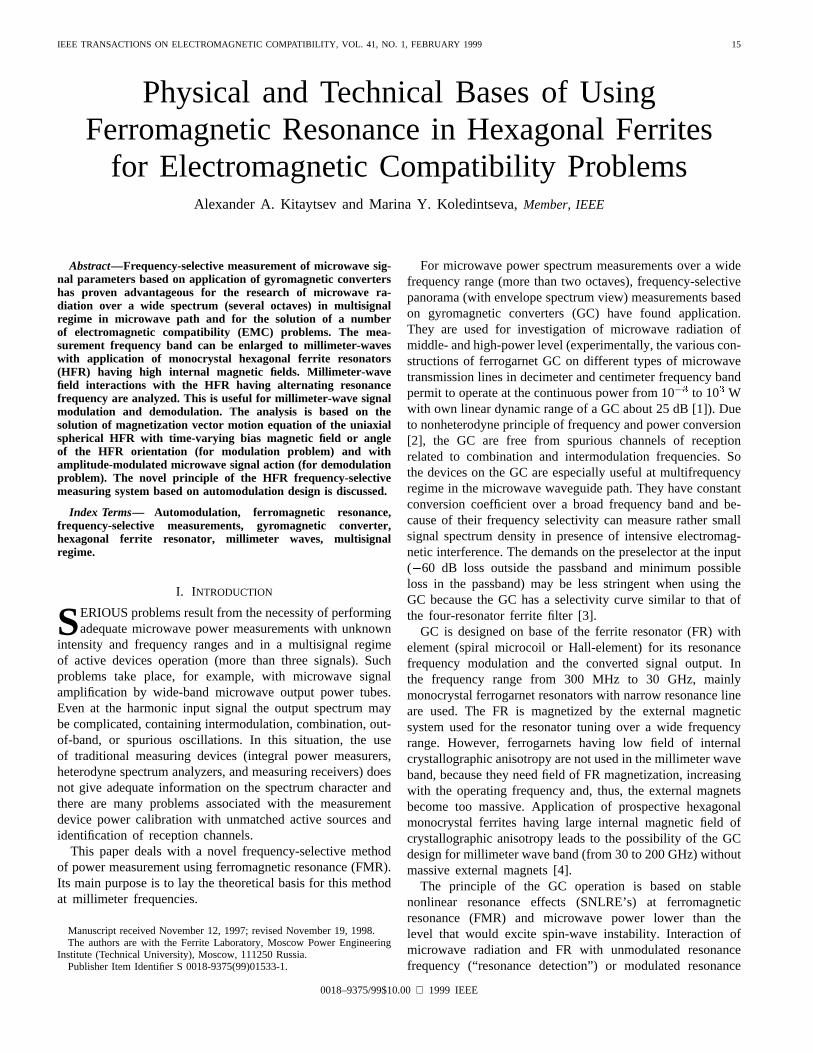
Fig. 1. Orientation of the main HFR vectors.
frequency (“cross-multiplication”) result in nonlinear relationsbetween transversal and longitudinal components of theFR magnetization vector [1], [2]. Thus, the longitudinalcomponent and envelope of microwave signal reradiated bythe FR contain information of spectrum power density ofmicrowave radiation at the resonance frequency.
At cross multiplication in the vicinity of the FMR the lon-gitudinal component of the FR magnetization vector containsthe harmonics of the modulation frequency [5]and so does the voltage in the output element (microcoil orHall element) . Each harmonic can be selected bythe proper filter of the converted signal at an intermediatefrequency. The amplitude of the harmonic depends on themicrowave signal power , relative detuning of the FRresonance frequency from that of the signal ,relative modulation frequency , normalized amplitudeof modulation , where is deviation of resonancefrequency, is frequency of modulation, and is the HFRresonance line width.
SNLRE’s have been already studied in crystallographically“isotropic” ferrogarnet FR [5]–[7]. SNLRE’s in the HFR aremore complicated, because of the large internal field of crys-tallographic anisotropy . The present paper considers theanalysis of these effects taking into account and its arbi-trary direction with respect to the constant field of externalmagnetization . It is the more general problem, and its so-lution should coincide with that for the “isotropic” case, wherethe crystallographic field and the angle .
II. THEORETICAL ANALYSIS
Theoretical analysis is based on nonlinear vector differentialmagnetization motion equation [8] with time-varying coeffi-cients. This approach is valid if the FR is a single-domain,magnetically uniaxial saturated particle of spherical form with
dimensions essentially less than the wavelength. In the generalcase of an arbitrarily oriented HFR with arbitrary modulationfrequencies, the solution of the problem is intractable. So wemake some simplifications, which correspond to real situationin GC design.
•HFR crystallographic anisotropy field is more than biasfield .
•Modulation frequency is essentially less than relaxation one.
Then we can use “quasi-static” approach based on appli-cation of the known tensor of the magnetic susceptibilityof the HFR. We consider small angles of magnetizationvector precession and small deviations of the HFR resonancefrequency, , so there is no difference on what typeof dissipation term to take into account [10]. For simplicity,we assume Landau–Lifshits damping usually used in thehexagonal ferrite susceptibility tensor [8], [11].
A. Interaction of the Harmonic Millimeter-WaveSignal with the HFR Having Alternating ResonanceFrequency—Modulation of Millimeter-Wave Signal
The HFR resonance frequency can be controlled in twoways. One way is the same as used in GC with ferrogarnets;that is, “field” control by alternating current in the microcoilsurrounding the FR [1]. The second way is specific for theHFR; it is “angular” control via deviation of the angle of
orientation. We shall consider both mentioned cases.As it follows from the condition of the uniaxial crystal
minimum magnetic energy, the equilibrium magnetic moment, the external (bias) magnetic field and the crystallo-
graphic anisotropy magnetic field are coplanar vectors [8],[10]. For definiteness, let us consider the magnetic moment
, see Fig. 1.
KITAYTSEV AND KOLEDINTSEVA: USING FERROMAGNETIC RESONANCE FOR EMC PROBLEMS 17
The components of the susceptibility tensor in general casedepend on angle [11], but here
(1)
where
(2)
(3)
where , , , is thedissipation parameter in Landau-Lifshits form [8]. The HFRresonance frequency is determined from the correspondingdeterminant set equal to zero
(4)
For both “field” and “angular” resonance frequency control wecan represent the resonance frequency at small amplitudes ofdeviation as following:
(5)
is proportional to the magnitude of bias magnetic fieldvariation at “field” control and to the deviation of the HFRorientation at “angular” control.
Since the frequency of modulation in the “quasi-static” caseis essentially less than that of the relaxation, the relationshipbetween the angles can be assumed as in the static case, whichfollows from the minimum of the magnetic energy of thecrystal [8]
(6)
(7)
Each tensor component contains real and imaginary terms
(8)
We can represent the millimeter wave transverse com-ponents of magnetization vector as oscillations with slowlyvarying amplitude and phase
at (9)
if the millimeter wave field has the components, (forinstance, mode H in rectangular waveguide with axis ofpropagation ), then [9]
(10)
where
and the amplitude can be expanded into Fourier series
(11)
Because of rather implicit form of this function, the Fourierexpansion may be evaluated numerically.
Harmonics of the envelopes of millimeter wave signals,coupled by the HFR into the waveguide (transfer and reflectioncoefficients), also carry information on the input power at thecenter frequency. They are determined via the HFR (with di-mensions essentially less than the wave length) representationas an elementary magnetic dipole radiating into the waveguide,the radiated field components depending on the magnetizationcomponents, and the latter, in their turn, depending on theradiated magnetic field (method of “self-matched field” [8]).
The envelope of millimeter wave magnetization compo-nents, taking into account coupling coefficientof the HFRwith waveguide, is expressed as [9]
(12)
where
is ferrite resonator volume, is wave norm [12], ispropagation constant of wave, are amplitudes ofthe millimeter wave magnetic field components.
The modulation coefficient of the transferred wave approxi-mately is found from the “self-matched field” problem solutionas [9]
(13)
Spectra of determine the spectra of modulation coef-ficient and, thus, the conversion coefficient at the chosenharmonic. The form of the modulation coefficient harmonicamplitudes versus the relative detuning co-incides with the form of corresponding harmonics of thesusceptibility tensor components and with the forms of anal-ogous dependencies for the “isotropic” case [5]–[7]. Theharmonic amplitudes almost linearly increase with the nor-malized amplitude of modulation growth at low
(“quasi-static” case).Amplitudes of the harmonics in the envelope of the trans-
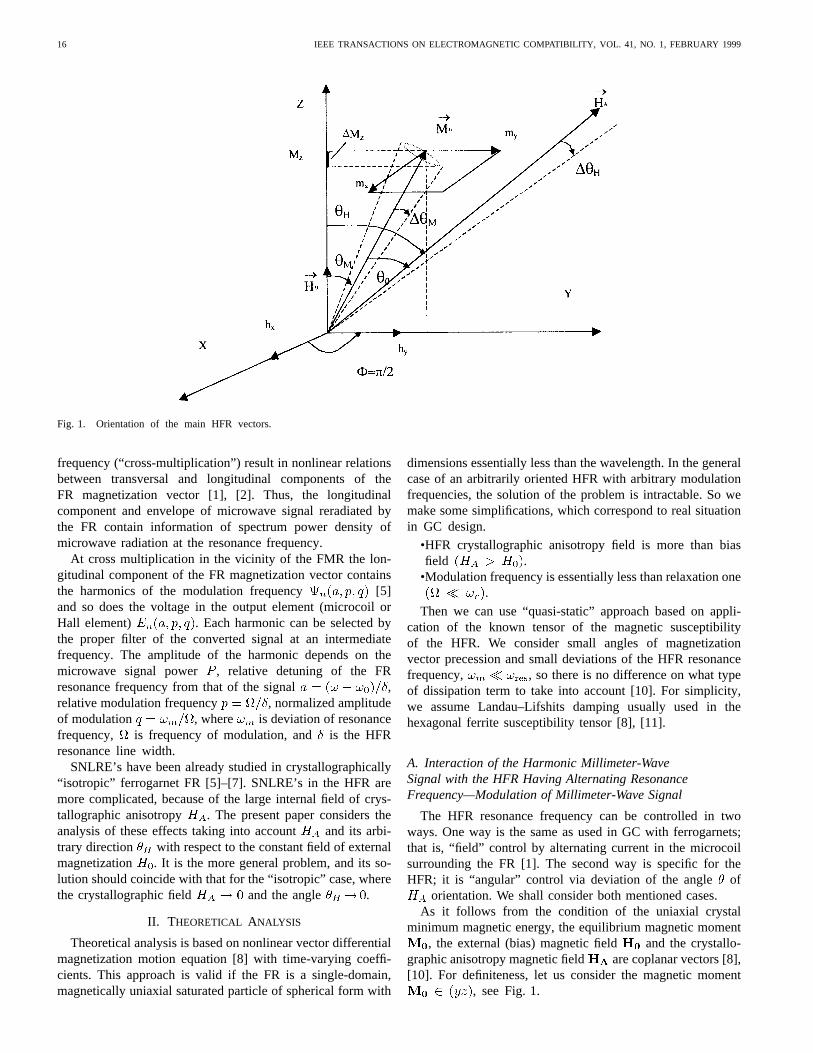
ferred signal are proportional to the intensity of the inputsignal and depend on a number of HFR physical parameters:anisotropy field, relaxation frequency, orientation, value ofthe external field of magnetization, waveguide path param-eters, and the point of the HFR placement in the waveguide.Maximum amplitude of any harmonic can be achieved atcertain combination of and angle of orientation for theferrite with given . Computations show that at the “field”control maximum amplitude of modulation on the firstharmonic of frequency corresponds to the “zero” orientation,
. At the “angular” control with fixed angular deviationmaximum amplitude of modulation is reached at the
optimum angle of orientation lying in the interval 30–70(see Fig. 2) [13].
18 IEEE TRANSACTIONS ON ELECTROMAGNETIC COMPATIBILITY, VOL. 41, NO. 1, FEBRUARY 1999
Fig. 2. Amplitude of the first harmonic of modulation frequency versus the HFR angle of orientation.
B. Interaction of the Modulated Signal withthe HFR—Demodulation
Now let us consider the case with the HFR excited bythe modulated millimeter wave signal having the followingcomponents of the magnetic field:
(14)
where , —modulated amplitude and phase, corre-spondingly.
Let us find voltage induced in spiral microcoil, surroundingthe HFR due to the variation of the longitudinal component ofthe magnetization vector. Since the relation between the varia-tion of the longitudinal component of the magnetization vectorand its transversal components is nonlinear [8], [14] then,following from the geometry of the problem, the variationof the is
(15)
and voltage induced in the microcoil is
(16)
where is the coefficient depending on the geometry andparameters of the microcoil.
Taking into account the relation between millimeter wavecomponents of the magnetization vector and the millimeterwave magnetic field via the tensor of magnetic susceptibility,we can obtain the expression for the voltagein microcoil.Derivation of the formulas is represented in the Appendix [see
(A.11), (A.15a), (A.15b)]
(17)
where
(18)
(19)
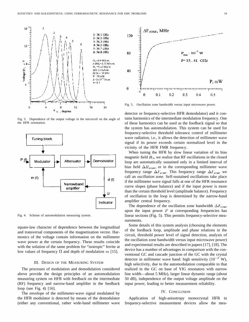
This output voltage has resonance character and achievesmaximum at the FMR by choosing proper external field ofmagnetization and angle of orientation (Fig. 3). Thevoltage increases with the reduction of the parameter, i.e.,with the decrease of the FMR line width. If the millimeterwave signal is unmodulated, the output voltage is equal tozero. If the signal has amplitude modulation with the depth
and frequency
(20)
then the voltage contains the first and the second harmonicsof the modulation frequency, because the component
in (17) is
(21)
and with the increase of the modulation frequencythevoltage rises linearly (in the limits of “quasi-static” ap-proximation at relatively low-modulation frequencies). Withthe growth of the depth of modulation the amplitudes ofthe voltage harmonics also increase: the first one linearly, thesecond one as a square.
It is important to note that there is no dependence on phaseof millimeter wave signal acting on the HFR, because of the
KITAYTSEV AND KOLEDINTSEVA: USING FERROMAGNETIC RESONANCE FOR EMC PROBLEMS 19
Fig. 3. Dependence of the output voltage in the microcoil on the angle ofthe HFR orientation.
Fig. 4. Scheme of automodulation measuring system.
square-law character of dependence between the longitudinaland transversal components of the magnetization vector. Har-monics of the voltage contain information on the millimeterwave power at the certain frequency. These results coincidewith the solution of the same problem for “isotropic” ferrite atlow values of frequency and depth of modulation [15].
III. D ESIGN OF THE MEASURING SYSTEM
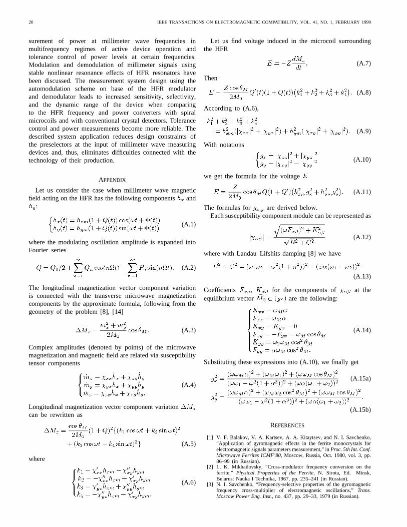
The processes of modulation and demodulation consideredabove provide the design principles of an automodulationmeasuring system on HFR with feedback on the intermediate(RF) frequency and narrow-band amplifier in the feedbackloop (see Fig. 4) [16].
The envelope of the millimeter-wave signal modulated bythe HFR modulator is detected by means of the demodulator(either any conventional, rather wide-band millimeter wave
Fig. 5. Oscillation zone bandwidth versus input microwave power.
detector or frequency-selective HFR demodulator) and it con-tains harmonics of the intermediate modulation frequency. Oneof these harmonics can be used as the feedback signal so thatthe system has automodulation. This system can be used forfrequency-selective threshold tolerance control of millimeterwave radiation, i.e., it allows the detection of millimeter wavesignal if its power exceeds certain normalized level in thevicinity of the HFR FMR frequency.
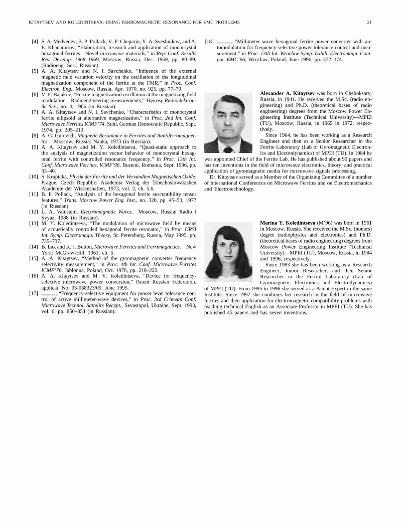
When tuning the HFR by slow linear variation of its biasmagnetic field , we realize that RF oscillations in the closedloop are automatically sustained only in a limited interval ofbias field , or in the corresponding millimeter wavefrequency range . This frequency range wecall an oscillation zone. Self-sustained oscillations take placeif the millimeter wave signal falls at one of the HFR resonancecurve slopes (phase balance) and if the input power is morethan the certain threshold level (amplitude balance). Frequencyof oscillation in the loop is determined by the narrow-bandamplifier central frequency.
The dependence of the oscillation zone bandwidthupon the input power at corresponding frequencies haslinear sections (Fig. 5). This permits frequency-selective mea-surements.
Some details of this system analysis (choosing the elementsof the feedback loop, amplitude and phase relations in thecircuit, threshold power level of signal detection, analysis ofthe oscillation zone bandwidth versus input microwave power)and experimental results are described in papers [17], [18]. Thedevice has a number of advantages in comparison with the con-ventional GC and cascade junction of the GC with the crystaldetector in millimeter wave band: high sensitivity (10W),high selectivity, due to the automodulation comparable to thatrealized in the GC on base of YIG resonators with narrowline width—about 5 MHz), larger linear dynamic range (about50 dB), independence of the output voltage amplitude on theinput power, leading to better measurement reliability.
IV. CONCLUSION
Application of high-anisotropy monocrystal HFR infrequency-selective measurement devices allow the mea-
20 IEEE TRANSACTIONS ON ELECTROMAGNETIC COMPATIBILITY, VOL. 41, NO. 1, FEBRUARY 1999
surement of power at millimeter wave frequencies inmultifrequency regimes of active device operation andtolerance control of power levels at certain frequencies.Modulation and demodulation of millimeter signals usingstable nonlinear resonance effects of HFR resonators havebeen discussed. The measurement system design using theautomodulation scheme on base of the HFR modulatorand demodulator leads to increased sensitivity, selectivity,and the dynamic range of the device when comparingto the HFR frequency and power converters with spiralmicrocoils and with conventional crystal detectors. Tolerancecontrol and power measurements become more reliable. Thedescribed system application reduces design constraints ofthe preselectors at the input of millimeter wave measuringdevices and, thus, eliminates difficulties connected with thetechnology of their production.
APPENDIX
Let us consider the case when millimeter wave magneticfield acting on the HFR has the following componentsand
:
(A.1)
where the modulating oscillation amplitude is expanded intoFourier series
(A.2)
The longitudinal magnetization vector component variationis connected with the transverse microwave magnetizationcomponents by the approximate formula, following from thegeometry of the problem [8], [14]
(A.3)
Complex amplitudes (denoted by points) of the microwavemagnetization and magnetic field are related via susceptibilitytensor components
(A.4)
Longitudinal magnetization vector component variationcan be rewritten as
(A.5)
where
(A.6)
Let us find voltage induced in the microcoil surroundingthe HFR
(A.7)
Then
(A.8)
According to (A.6),
(A.9)
With notations
(A.10)
we get the formula for the voltage
(A.11)
The formulas for are derived below.Each susceptibility component module can be represented as
(A.12)
where with Landau–Lifshits damping [8] we have
(A.13)
Coefficients , for the components of at theequilibrium vector are the following:
(A.14)
Substituting these expressions into (A.10), we finally get
(A.15a)
(A.15b)
REFERENCES
[1] V. F. Balakov, V. A. Kartsev, A. A. Kitaytsev, and N. I. Savchenko,“Application of gyromagnetic effects in the ferrite monocrystals forelectromagnetic signals parameters measurement,” inProc. 5th Int. Conf.Microwave Ferrites ICMF’80, Moscow, Russia, Oct. 1980, vol. 3, pp.86–99 (in Russian).
[2] L. K. Mikhailovsky, “Cross-modulator frequency conversion on theferrite,” Physical Properties of the Ferrite, N. Sirota, Ed. Minsk,Belarus: Nauka I Technika, 1967, pp. 235–241 (in Russian).
[3] N. I. Savchenko, “Frequency-selective properties of the gyromagneticfrequency cross-multiplier of electromagnetic oscillations,”Trans.Moscow Power Eng. Inst., no. 437, pp. 29–33, 1979 (in Russian).
KITAYTSEV AND KOLEDINTSEVA: USING FERROMAGNETIC RESONANCE FOR EMC PROBLEMS 21
[4] S. A. Medvedev, B. P. Pollack, V. P. Cheparin, Y. A. Sveshnikov, and A.E. Khanamirov, “Elaboration, research and application of monocrystalhexagonal ferrites—Novel microwave materials,” inRep. Conf. ResultsRes. Develop. 1968–1969, Moscow, Russia, Dec. 1969, pp. 80–89,(Radioeng. Sec., Russian).
[5] A. A. Kitaytsev and N. I. Savchenko, “Influence of the externalmagnetic field variation velocity on the oscillation of the longitudinalmagnetization component of the ferrite at the FMR,” inProc. Conf.Electron. Eng., Moscow, Russia, Apr. 1970, no. 925, pp. 77–79.
[6] V. F. Balakov, “Ferrite magnetization oscillation at the magnetizing fieldmodulation—Radioengineering measurements,”Voprosy Radioelektron-iki Ser., no. 4, 1966 (in Russian).
[7] A. A. Kitaytsev and N. I. Savchenko, “Characteristics of monocrystalferrite ellipsoid at alternative magnetization,” inProc. 2nd Int. Conf.Microwave Ferrites ICMF’74, Suhl, German Democratic Republic, Sept.1974, pp. 205–213.
[8] A. G. Gurevich,Magnetic Resonance in Ferrites and Aantiferromagnet-ics. Moscow, Russia: Nauka, 1973 (in Russian).
[9] A. A. Kitaytsev and M. Y. Koledintseva, “Quasi-static approach tothe analysis of magnetization vector behavior of monocrystal hexag-onal ferrite with controlled resonance frequency,” inProc. 13th Int.Conf. Microwave Ferrites, ICMF’96, Busteni, Romania, Sept. 1996, pp.33–40.
[10] S. Krupicka,Physik der Ferrite und der Vervandten Magnetischen Oxide.Prague, Czech Republic: Akademia Verlag der TshechoslowakishenAkademie der Wissenshaften, 1973, vol. 2, ch. 5.6.
[11] B. P. Pollack, “Analysis of the hexagonal ferrite susceptibility tensorfeatures,”Trans. Moscow Power Eng. Inst., no. 320, pp. 45–53, 1977(in Russian).
[12] L. A. Vainstein, Electromagnetic Waves. Moscow, Russia: Radio iSvyaz, 1988 (in Russian).
[13] M. Y. Koledintseva, “The modulation of microwave field by meansof acoustically controlled hexagonal ferrite resonator,” inProc. URSIInt. Symp. Electromagn. Theory, St. Petersburg, Russia, May 1995, pp.735–737.
[14] B. Lax and K. J. Button,Microwave Ferrites and Ferrimagnetics. NewYork: McGraw-Hill, 1962, ch. 5.
[15] A. A. Kitaytsev, “Method of the gyromagnetic converter frequencyselectivity measurement,” inProc. 4th Int. Conf. Microwave FerritesICMF’78, Jablonna, Poland, Oct. 1978, pp. 218–222.
[16] A. A. Kitaytsev and M. Y. Koledintseva, “Device for frequency-selective microwave power conversion,” Patent Russian Federation,applicat. No. 93-038323/09, June 1995.
[17] , “Frequency-selective equipment for power level tolerance con-trol of active millimeter-wave devices,” inProc. 3rd Crimean Conf.Microwave Technol. Sattelite Recept., Sevastopol, Ukraine, Sept. 1993,vol. 6, pp. 850–854 (in Russian).
[18] , “Millimeter wave hexagonal ferrite power converter with au-tomodulation for frequency-selective power tolerance control and mea-surement,” inProc. 13th Int. Wroclaw Symp. Exhib. Electromagn. Com-pat. EMC’96, Wroclaw, Poland, June 1996, pp. 372–374.
Alexander A. Kitaytsev was born in Cheboksary,Russia, in 1941. He received the M.Sc. (radio en-gineering) and Ph.D. (theoretical bases of radioengineering) degrees from the Moscow Power En-gineering Institute (Technical University)—MPEI(TU), Moscow, Russia, in 1965 in 1972, respec-tively.
Since 1964, he has been working as a ResearchEngineer and then as a Senior Researcher in theFerrite Laboratory (Lab of Gyromagnetic Electron-ics and Electrodynamics) of MPEI (TU). In 1984 he
was appointed Chief of the Ferrite Lab. He has published about 90 papers andhas ten inventions in the field of microwave electronics, theory, and practicalapplication of gyromagnetic media for microwave signals processing.
Dr. Kitaytsev served as a Member of the Organizing Committee of a numberof International Conferences on Microwave Ferrites and on Electromechanicsand Electrotechnology.
Marina Y. Koledintseva (M’96) was born in 1961in Moscow, Russia. She received the M.Sc. (honors)degree (radiophysics and electronics) and Ph.D.(theoretical bases of radio engineering) degrees fromMoscow Power Engineering Institute (TechnicalUniversity)—MPEI (TU), Moscow, Russia, in 1984and 1996, respectively.
Since 1983 she has been working as a ResearchEngineer, Junior Researcher, and then SeniorResearcher in the Ferrite Laboratory (Lab ofGyromagnetic Electronics and Electrodynamics)
of MPEI (TU). From 1995 to 1996 she served as a Patent Expert in the sameInstitute. Since 1997 she combines her research in the field of microwaveferrites and their application for electromagnetic compatibility problems withteaching technical English as an Associate Professor in MPEI (TU). She haspublished 45 papers and has seven inventions.