Embed Size (px)
Citation preview
Physical and Logical Topologies
Lecture 2Mariusz Nowostawski
INFO333
Content
• Network Architecture• Physical Topology
– Bus, Ring, Star, Mesh, Tree, Hybrid
• Logical Topology• Circuit Switching• Message Switching• Packet Switching• Ethernet
– CSMA/CD
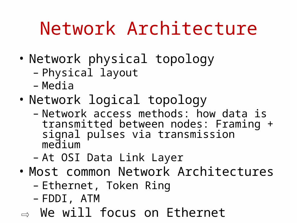
Network Architecture• Network physical topology
– Physical layout– Media
• Network logical topology– Network access methods: how data is transmitted
between nodes: Framing + signal pulses via transmission medium
– At OSI Data Link Layer• Most common Network Architectures
– Ethernet, Token Ring– FDDI, ATM
⇨ We will focus on Ethernet
Physical Topology
• Physical layout of the network nodes– Broad description of the network: no detail about
device types, connection methods, addressing, ...– 3 most common topologies: – Bus, Star, Ring– Network administrator needs to understand
physical topology• Troubleshooting, upgrading network infrastructure,
effect on chosen logical topology, etc.
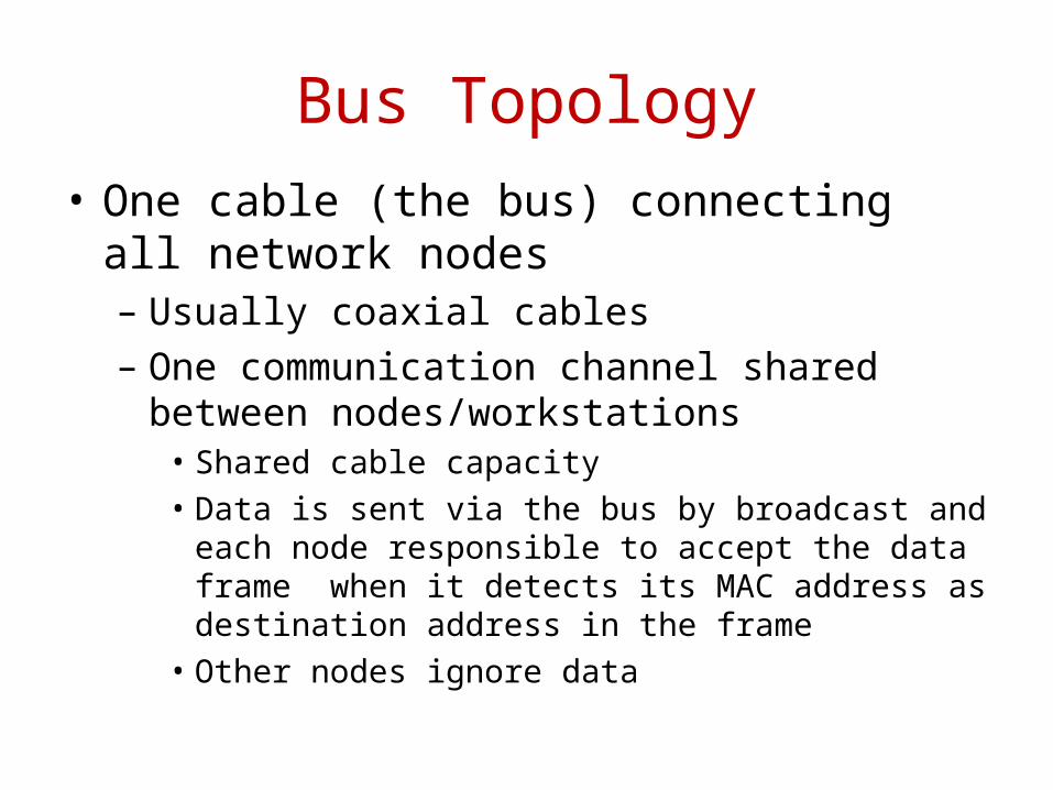
Bus Topology• One cable (the bus) connecting all network nodes
– Usually coaxial cables– One communication channel shared between
nodes/workstations • Shared cable capacity• Data is sent via the bus by broadcast and each node
responsible to accept the data frame when it detects its MAC address as destination address in the frame
• Other nodes ignore data
Bus Topology
– No connecting device– Two end-points: terminators = 50 Ohm resistors
• Terminators absorb signal ⇨ No signal reflection (noise)
Bus Topology• Advantages
– Easy and inexpensive to set-up• Disadvantages
– Lack of scalability• more nodes ⇨ performance degrades on unique channel
– Difficulty to troubleshoot• Error may occur anywhere along the bus
– No fault-tolerance• Network down if cable breaks
⇨ Usually for network limited to 10 nodes⇨ Often combined with other topologies
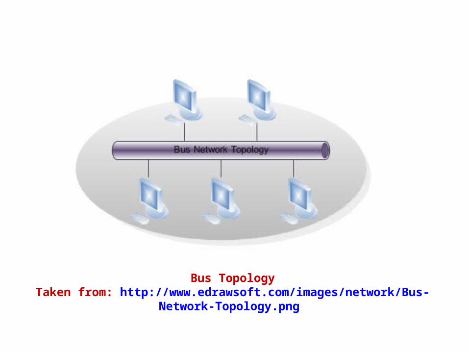
Bus TopologyTaken from: http://www.edrawsoft.com/images/network/Bus-Network-Topology.png
Star Topology
• All nodes are connected to central device called concentrator (or hub) or Multi-station Access Unit (MAU) – One cable connects two devices– No terminator
• Usually twisted-pair cables or fiber cables
Star Topology• Advantages
– Better resilience per segment: problem isolation– More expensive than Bus: hubs cost more than Bus
connectors – Easier to troubleshoot than Bus– Scalable
• Disadvantages– More cabling than Bus and Ring– More configuration– Failure at concentrator will affect all the network
⇨ Frequent topology: lots of support
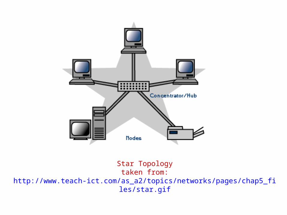
Star Topologytaken from: http://www.teach-ict.com/as_a2/topics/networks/pages/chap5_files/star.gif
Ring Topology
• Similar to the Bus but all the devices connected to a common cable forming a closed loop: no begin/end
• Usually twisted-pair cables or fiber optic cables
Ring Topology
• Packets are transmitted in one direction of ring– Each node accepts/responds to its packets and forward
remaining packets to next node in ring– Usually a token (3-byte packet) is used
• Sending node with token transmits: data + token through ring• Destination node picks-up data frame and returns ACK via ring
to sending node• Sending node releases token to next node in ring
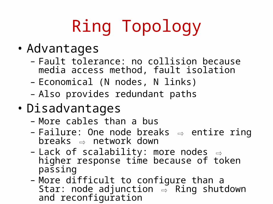
Ring Topology• Advantages
– Fault tolerance: no collision because media access method, fault isolation
– Economical (N nodes, N links)– Also provides redundant paths
• Disadvantages– More cables than a bus– Failure: One node breaks ⇨ entire ring breaks ⇨ network
down– Lack of scalability: more nodes ⇨ higher response time
because of token passing– More difficult to configure than a Star: node adjunction ⇨
Ring shutdown and reconfiguration
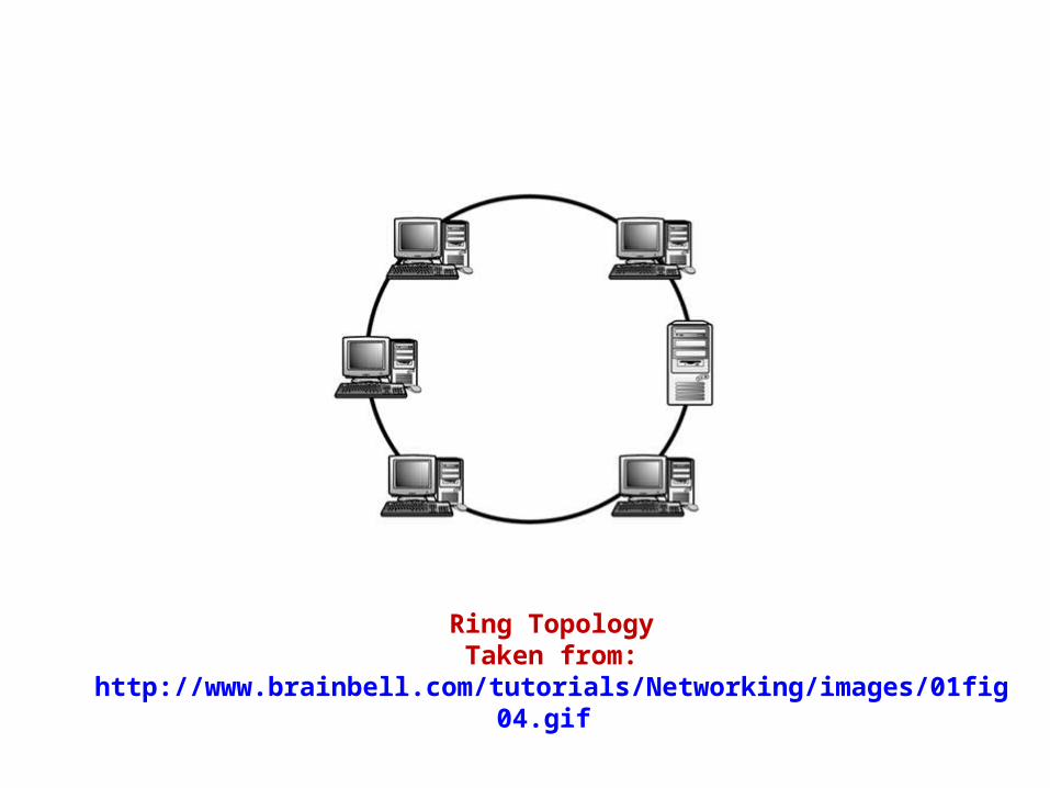
Ring TopologyTaken from: http://www.brainbell.com/tutorials/Networking/images/01fig04.gif
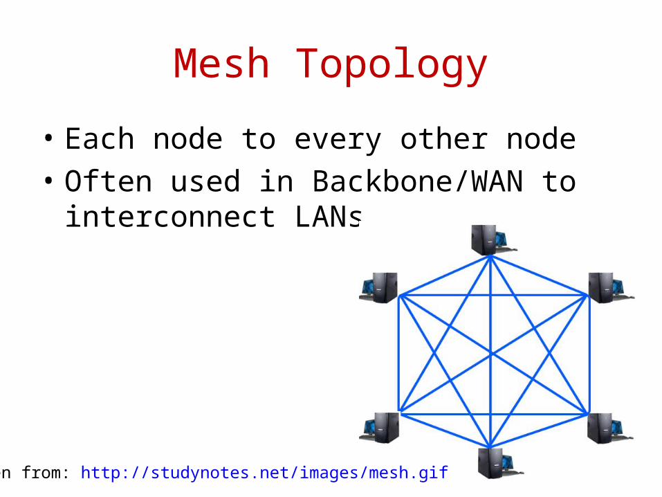
Mesh Topology
• Each node to every other node• Often used in Backbone/WAN to interconnect
LANs
Taken from: http://studynotes.net/images/mesh.gif
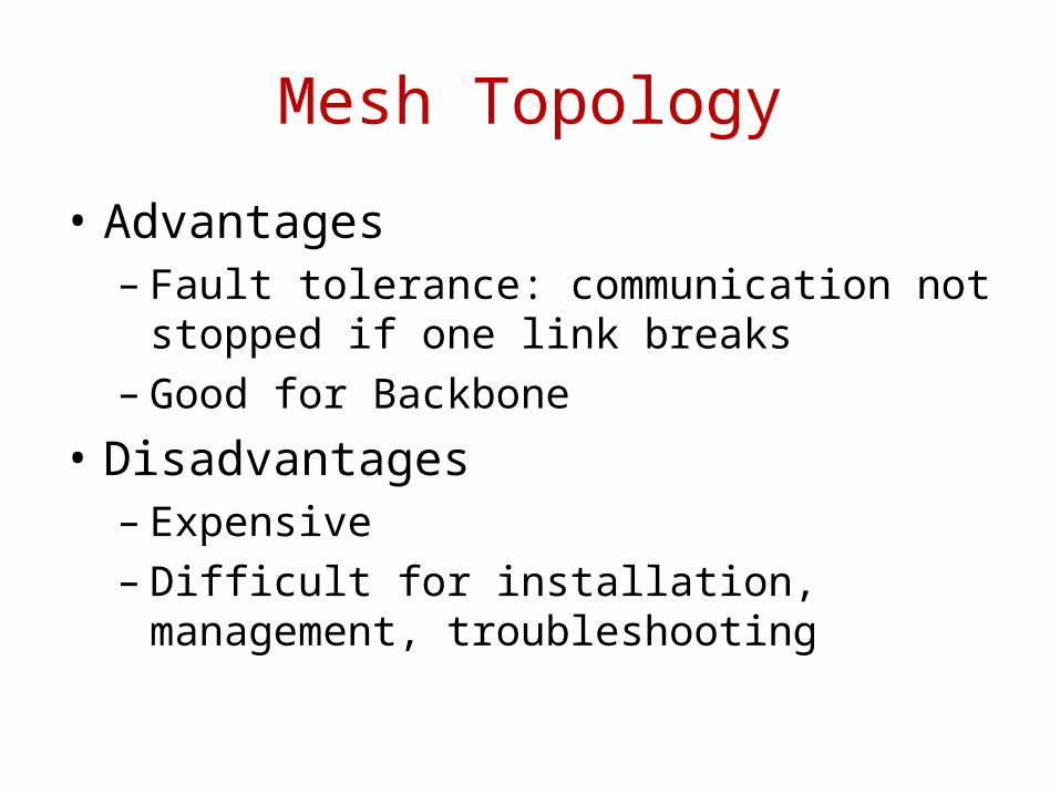
Mesh Topology
• Advantages– Fault tolerance: communication not stopped if
one link breaks– Good for Backbone
• Disadvantages– Expensive– Difficult for installation, management,
troubleshooting
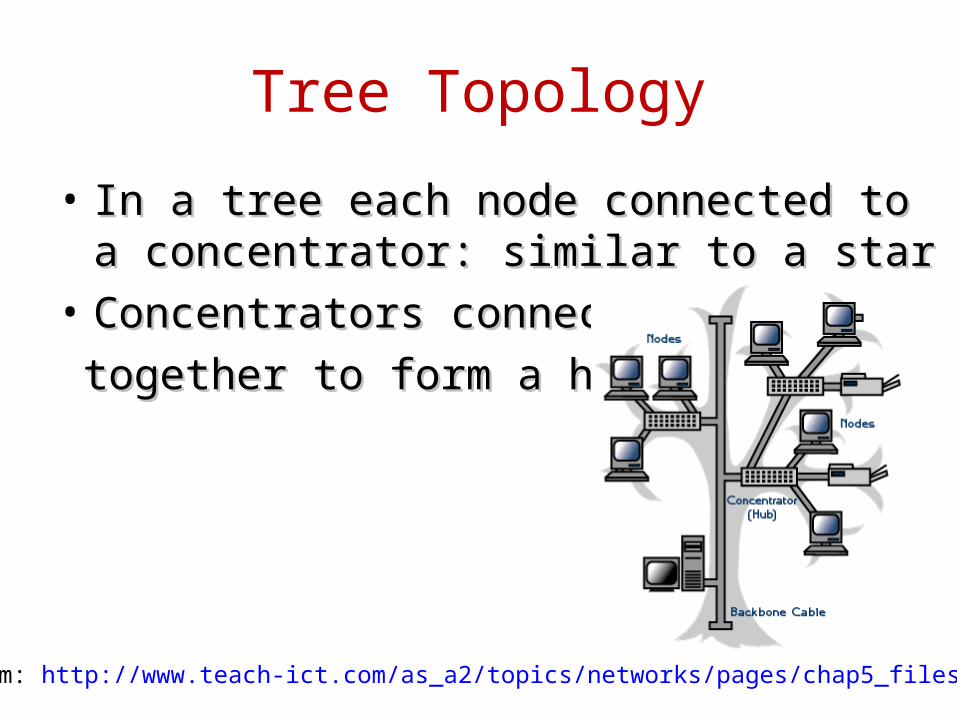
Tree Topology
• In a tree each node connected to a concentrator: In a tree each node connected to a concentrator: similar to a starsimilar to a star
• Concentrators connectedConcentrators connected together to form a hierarchytogether to form a hierarchy
Taken from: http://www.teach-ict.com/as_a2/topics/networks/pages/chap5_files/tree.gif
Hybrid Topologies
• Simple topology are too restrictive– Scalability, performance, etc.
• Usually physical topology combines Bus, Star and Ring
• Two examples– Star-Wired Bus
• Groups of nodes are star-connected hubs• Hubs are connected together via a Bus
– Star-Wired Ring• Physically nodes are connected via a Star• Data is transmitted between node using token passing method
Logical Topology
• Network access methods– How data is transmitted between nodes
• Three methods used for all network architectures for connection creation– Circuit switching– Message switching– Packet switching
Circuit Switching
• Connection between two nodes is created before nodes transmit: circuit
• Bandwidth is dedicated to the circuit until end of connection– Not economical: waste of bandwidth
• Data follows the same circuit– Dedicated path ideal for audio and video
applications
• Used by ISDN and ATM

Message Switching
• Uses the store and forward principle– Connections is established between two nodes– Information is sent from node 1 to node 2– Connection is broken between node 1 and node 2– Node 2 stored and forward the information it
received to node 3• Nodes need to have enough resources: memory and
processing to store and forward data
Packet Switching• Data is broken as packets• Packets are transported using any path of the
network to the destination– Usually the fastest path is used based on routing
method• No bandwidth waste due to open connection
– Use of destination address and sequence number to get and rebuild packets at destination node
• Takes time: may be not suitable for live data (audio and video)
• Intermediary nodes do not process data
• Internet is a packet-switched network
Ethernet• Ethernet originally developed by Xerox in 1970s
• Widely used today for network architectures• IEEE 802 standards– Data Link and Physical layers– LAN, WAN and Wireless networks• Several specifications of 802 standards– 802.3: CSMA/CD (see next slides)– 803.5: Token Ring– 802.11: Wireless technologies– not exhaustive: Evolving specifications⇨ We will focus on 802.3 since it is used by
most Ethernet networks
802.3: CSMA/CD (1)
• Carrier Sense Multiple Access with Collision Detection– Defines Ethernet network access method– Developed in 1960s at University of Hawaii– Adopted by Xerox in 1970 and further developed by
Xerox, DEC and Intel– Standardized at beginning of 1980s by IEEE
• Specifications precise transmission rates, cable types, maximum and minimum cable lengths
802.3: CSMA/CD (2)• Carrier Sense
– NICs listen to network to sense if a signal (carrier) is detected another node is transmitting⇨
– If no signal, channel is free the node can send data⇨
• Multiple Access– Several nodes can access the media and sense signal
simultaneously• Collision Detection
– Nodes NICs can detect collision: when two nodes transmit data in the network at the same time
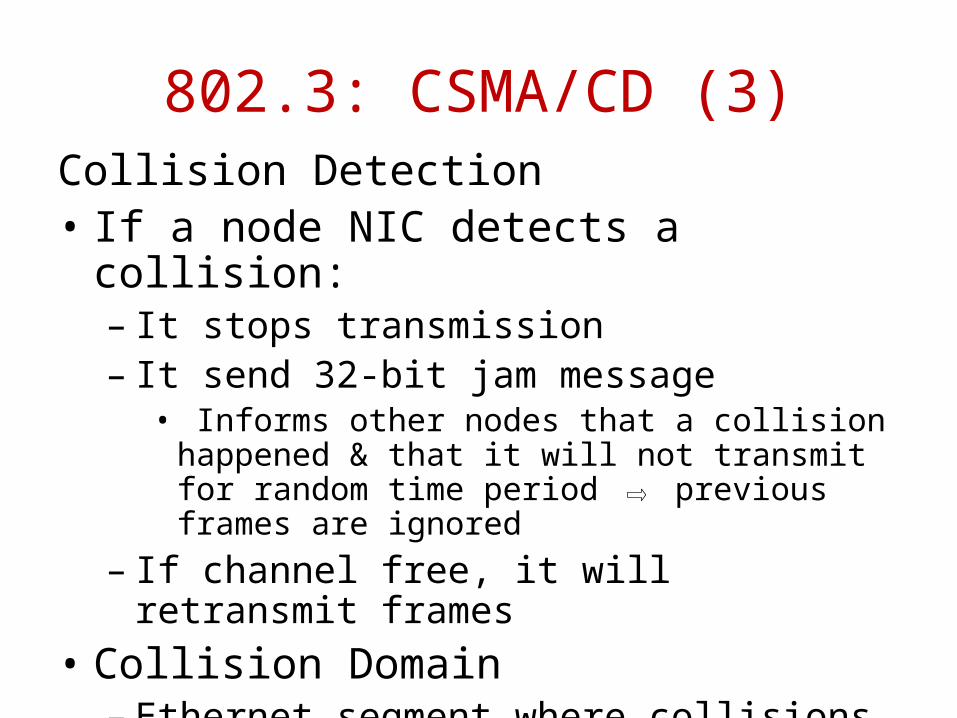
802.3: CSMA/CD (3)Collision Detection• If a node NIC detects a collision:
– It stops transmission– It send 32-bit jam message
• Informs other nodes that a collision happened & that it will not transmit for random time period previous ⇨frames are ignored
– If channel free, it will retransmit frames• Collision Domain
– Ethernet segment where collisions can happen
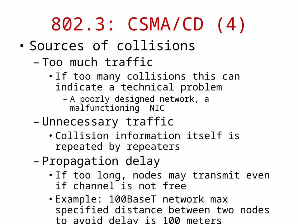
802.3: CSMA/CD (4)• Sources of collisions
– Too much traffic• If too many collisions this can indicate a technical
problem– A poorly designed network, a malfunctioning NIC
– Unnecessary traffic• Collision information itself is repeated by repeaters
– Propagation delay• If too long, nodes may transmit even if channel is not
free• Example: 100BaseT network max specified distance
between two nodes to avoid delay is 100 meters
802.3: CSMA/CD (5)
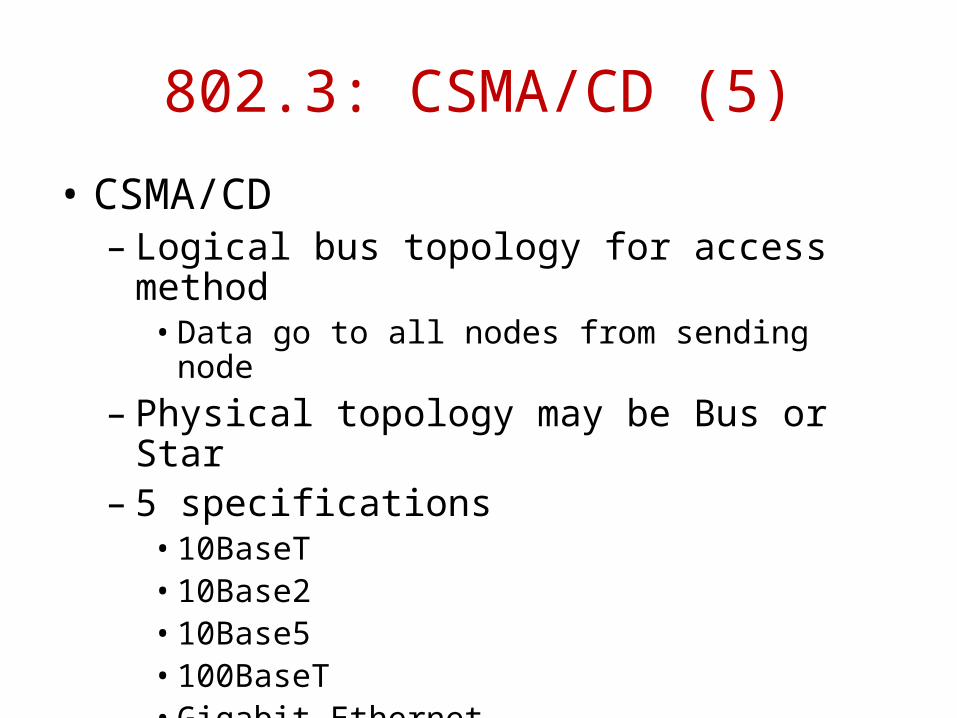
• CSMA/CD– Logical bus topology for access method
• Data go to all nodes from sending node– Physical topology may be Bus or Star– 5 specifications
• 10BaseT• 10Base2• 10Base5• 100BaseT• Gigabit Ethernet

802.3: CSMA/CD (6)• 10BaseT
– Twisted-pair cables– Transmission rate: 10 Mbps baseband– Physical topology: Star– Segment length: 2 to 100 meters
• 10Base2 (Thin Ethernet)– Coaxial cables– Transmission rate: 10 Mbps baseband– Physical topology: Bus– Max segment length: 185 meters– Max: 30 hosts per segment
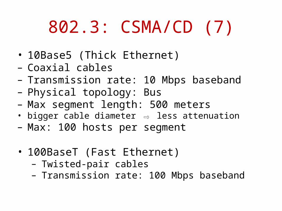
802.3: CSMA/CD (7)• 10Base5 (Thick Ethernet)– Coaxial cables– Transmission rate: 10 Mbps baseband– Physical topology: Bus– Max segment length: 500 meters • bigger cable diameter ⇨ less attenuation– Max: 100 hosts per segment
• 100BaseT (Fast Ethernet)– Twisted-pair cables– Transmission rate: 100 Mbps baseband
802.3: CSMA/CD (8)
• Gigabit Ethernet– Transmission rate: 1 Gbps baseband– IEEE 802.3ab Gigabit Ethernet over UDP
(1000BaseT)– IEEE 802.3z Gigabit Ethernet over fiber
(1000BaseX)
References
• CCNA – Guide to Cisco Networking – Third edition – Kelly Claude and Kelly Cannon