Embed Size (px)
Citation preview

Phys 0175 Midterm Exam III Solutions Apr 3, 2008
1. (8 pts) A particular capacitor has a separation between its plates of 0.03 mm. The
area of one plate is 16 m2. The capacitor is initially uncharged.
(a) (4 pts) Draw a graph of the amount of charge on one plate of the capacitor vs.
time, starting from the moment the capacitor is connected to a bulb and two
ordinary 1.5 V batteries. Your graph should extend slightly past the time when
the bulb goes out.
time
char
ge
(b) (4 pts) The circuit remains connected several minutes after the bulb has gone
out. How much charge is now on the positive plate of the capacitor? Start from
physics principles. Show your work clearly.
The potential decrease across the capacitor will become the same as the potential
increase across the batteries, which is 3.0 V. The electric field inside a capacitor
E =Q/A
ε0=
∆V
d
=⇒ Q =ε0A∆V
d
=8.85× 10⁻¹² C2/(N ·m2)× 16 m2 × 3.0 V
0.03× 10⁻³ m
= 1.4× 10⁻⁵ C .
1
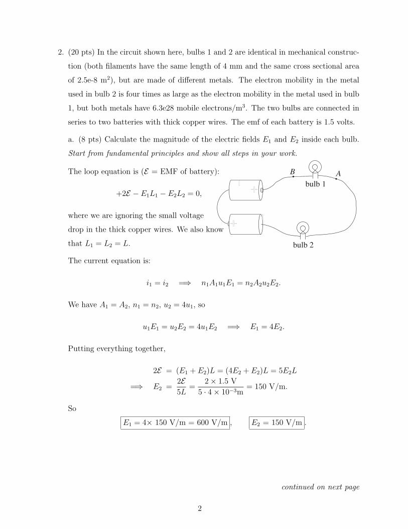
2. (20 pts) In the circuit shown here, bulbs 1 and 2 are identical in mechanical construc-
tion (both filaments have the same length of 4 mm and the same cross sectional area
of 2.5e-8 m2), but are made of different metals. The electron mobility in the metal
used in bulb 2 is four times as large as the electron mobility in the metal used in bulb
1, but both metals have 6.3e28 mobile electrons/m3. The two bulbs are connected in
series to two batteries with thick copper wires. The emf of each battery is 1.5 volts.
a. (8 pts) Calculate the magnitude of the electric fields E1 and E2 inside each bulb.
Start from fundamental principles and show all steps in your work.
+ -
+- bulb 1
bulb 2
B AThe loop equation is (E = EMF of battery):
+2E − E1L1 − E2L2 = 0,
where we are ignoring the small voltage
drop in the thick copper wires. We also know
that L1 = L2 = L.
The current equation is:
i1 = i2 =⇒ n1A1u1E1 = n2A2u2E2.
We have A1 = A2, n1 = n2, u2 = 4u1, so
u1E1 = u2E2 = 4u1E2 =⇒ E1 = 4E2.
Putting everything together,
2E = (E1 + E2)L = (4E2 + E2)L = 5E2L
=⇒ E2 =2E5L
=2× 1.5 V
5 · 4× 10−3m= 150 V/m.
So
E1 = 4× 150 V/m = 600 V/m , E2 = 150 V/m .
continued on next page
2
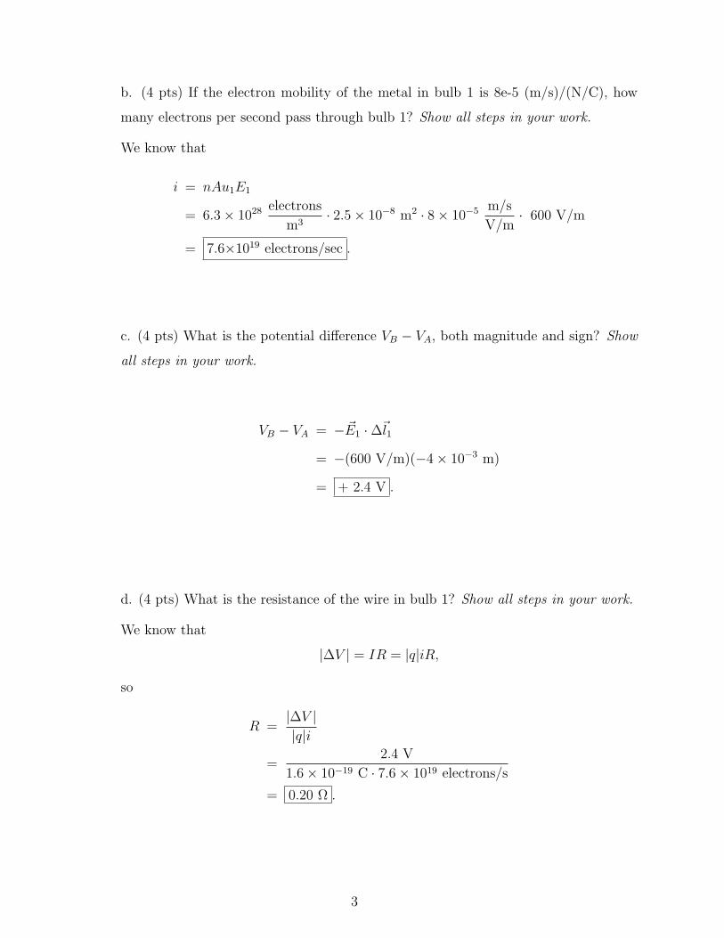
b. (4 pts) If the electron mobility of the metal in bulb 1 is 8e-5 (m/s)/(N/C), how
many electrons per second pass through bulb 1? Show all steps in your work.
We know that
i = nAu1E1
= 6.3× 1028 electrons
m3· 2.5× 10−8 m2 · 8× 10−5 m/s
V/m· 600 V/m
= 7.6×10¹⁹ electrons/sec .
c. (4 pts) What is the potential difference VB − VA, both magnitude and sign? Show
all steps in your work.
VB − VA = − ~E1 ·∆~l1
= −(600 V/m)(−4× 10−3 m)
= + 2.4 V .
d. (4 pts) What is the resistance of the wire in bulb 1? Show all steps in your work.
We know that
|∆V | = IR = |q|iR,
so
R =|∆V ||q|i
=2.4 V
1.6× 10−19 C · 7.6× 1019 electrons/s
= 0.20 Ω .
3
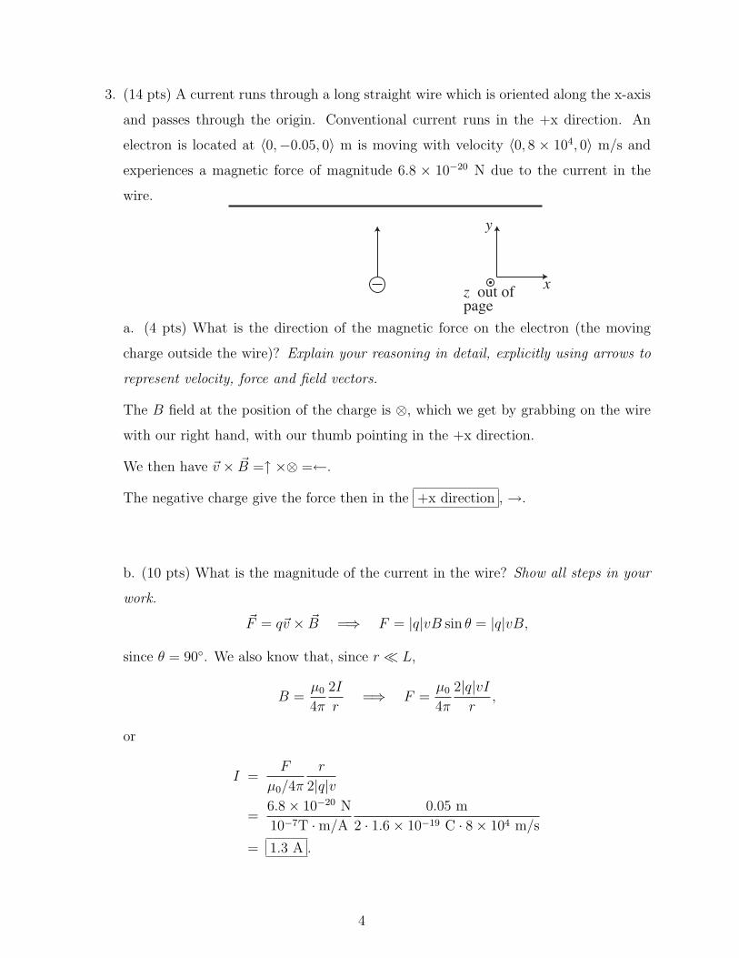
3. (14 pts) A current runs through a long straight wire which is oriented along the x-axis
and passes through the origin. Conventional current runs in the +x direction. An
electron is located at 〈0,−0.05, 0〉 m is moving with velocity 〈0, 8 × 10⁴, 0〉 m/s and
experiences a magnetic force of magnitude 6.8 × 10⁻²⁰ N due to the current in the
wire.
y
xz out ofpage
a. (4 pts) What is the direction of the magnetic force on the electron (the moving
charge outside the wire)? Explain your reasoning in detail, explicitly using arrows to
represent velocity, force and field vectors.
The B field at the position of the charge is ⊗, which we get by grabbing on the wire
with our right hand, with our thumb pointing in the +x direction.
We then have ~v × ~B =↑ ×⊗ =←.
The negative charge give the force then in the +x direction , →.
b. (10 pts) What is the magnitude of the current in the wire? Show all steps in your
work.
~F = q~v × ~B =⇒ F = |q|vB sin θ = |q|vB,
since θ = 90. We also know that, since r L,
B =µ0
4π
2I
r=⇒ F =
µ0
4π
2|q|vIr
,
or
I =F
µ0/4π
r
2|q|v
=6.8× 10⁻²⁰ N
10−7T ·m/A0.05 m
2 · 1.6× 10−19 C · 8× 104 m/s
= 1.3 A .
4
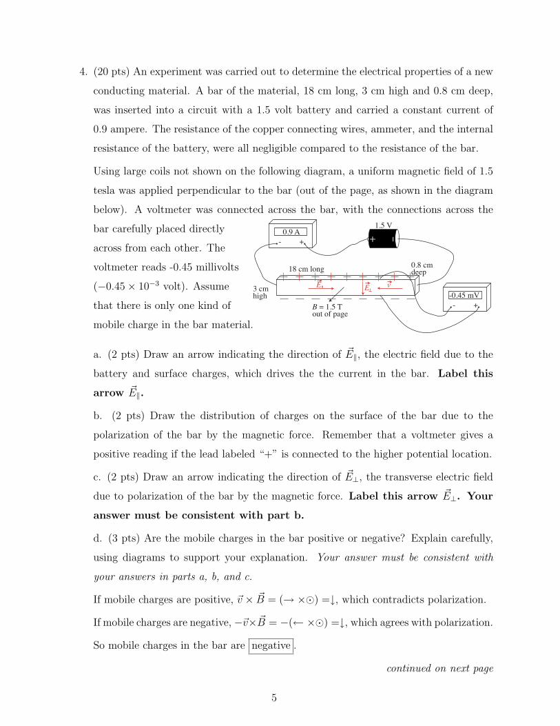
4. (20 pts) An experiment was carried out to determine the electrical properties of a new
conducting material. A bar of the material, 18 cm long, 3 cm high and 0.8 cm deep,
was inserted into a circuit with a 1.5 volt battery and carried a constant current of
0.9 ampere. The resistance of the copper connecting wires, ammeter, and the internal
resistance of the battery, were all negligible compared to the resistance of the bar.
Using large coils not shown on the following diagram, a uniform magnetic field of 1.5
tesla was applied perpendicular to the bar (out of the page, as shown in the diagram
below). A voltmeter was connected across the bar, with the connections across the
bar carefully placed directly
across from each other. The
voltmeter reads -0.45 millivolts
(−0.45× 10⁻³ volt). Assume
that there is only one kind of
mobile charge in the bar material.
+ -
0.9 A- +
1.5 V
-0.45 mV- +B = 1.5 T
out of page
18 cm long
3 cmhigh
0.8 cmdeep
E E v
a. (2 pts) Draw an arrow indicating the direction of ~E‖, the electric field due to the
battery and surface charges, which drives the the current in the bar. Label this
arrow ~E‖.
b. (2 pts) Draw the distribution of charges on the surface of the bar due to the
polarization of the bar by the magnetic force. Remember that a voltmeter gives a
positive reading if the lead labeled “+” is connected to the higher potential location.
c. (2 pts) Draw an arrow indicating the direction of ~E⊥, the transverse electric field
due to polarization of the bar by the magnetic force. Label this arrow ~E⊥. Your
answer must be consistent with part b.
d. (3 pts) Are the mobile charges in the bar positive or negative? Explain carefully,
using diagrams to support your explanation. Your answer must be consistent with
your answers in parts a, b, and c.
If mobile charges are positive, ~v × ~B = (→ ×) =↓, which contradicts polarization.
If mobile charges are negative, −~v× ~B = −(← ×) =↓, which agrees with polarization.
So mobile charges in the bar are negative .
continued on next page
5
e. (2 pts) Draw an arrow indicating the direction ~v, the drift velocity of the mobile
charges in the bar. Label this arrow ~v. Your answer must be consistent with your
answers in parts a, b, c, d.
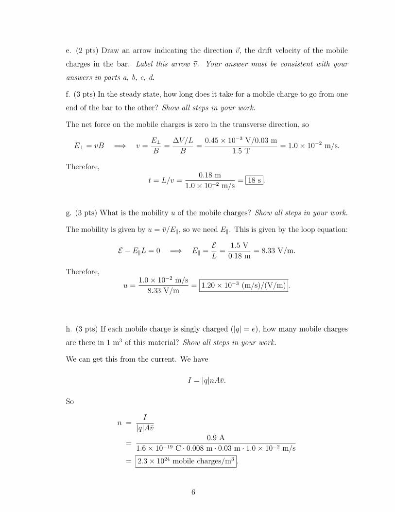
f. (3 pts) In the steady state, how long does it take for a mobile charge to go from one
end of the bar to the other? Show all steps in your work.
The net force on the mobile charges is zero in the transverse direction, so
E⊥ = vB =⇒ v =E⊥B
=∆V/L
B=
0.45× 10⁻³ V/0.03 m
1.5 T= 1.0× 10⁻² m/s.
Therefore,
t = L/v =0.18 m
1.0× 10⁻² m/s= 18 s .
g. (3 pts) What is the mobility u of the mobile charges? Show all steps in your work.
The mobility is given by u = v/E‖, so we need E‖. This is given by the loop equation:
E − E‖L = 0 =⇒ E‖ =EL
=1.5 V
0.18 m= 8.33 V/m.
Therefore,
u =1.0× 10⁻² m/s
8.33 V/m= 1.20× 10⁻³ (m/s)/(V/m) .
h. (3 pts) If each mobile charge is singly charged (|q| = e), how many mobile charges
are there in 1 m3 of this material? Show all steps in your work.
We can get this from the current. We have
I = |q|nAv.
So
n =I
|q|Av
=0.9 A
1.6× 10−19 C · 0.008 m · 0.03 m · 1.0× 10−2 m/s
= 2.3× 1024 mobile charges/m3 .
6
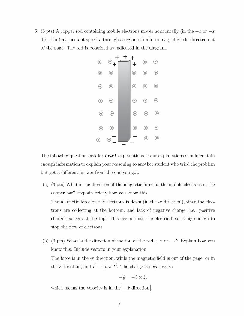
5. (6 pts) A copper rod containing mobile electrons moves horizontally (in the +x or −x
direction) at constant speed v through a region of uniform magnetic field directed out
of the page. The rod is polarized as indicated in the diagram.
The following questions ask for brief explanations. Your explanations should contain
enough information to explain your reasoning to another student who tried the problem
but got a different answer from the one you got.
(a) (3 pts) What is the direction of the magnetic force on the mobile electrons in the
copper bar? Explain briefly how you know this.
The magnetic force on the electrons is down (in the -y direction), since the elec-
trons are collecting at the bottom, and lack of negative charge (i.e., positive
charge) collects at the top. This occurs until the electric field is big enough to
stop the flow of electrons.
(b) (3 pts) What is the direction of motion of the rod, +x or −x? Explain how you
know this. Include vectors in your explanation.
The force is in the -y direction, while the magnetic field is out of the page, or in
the z direction, and ~F = q~v × ~B. The charge is negative, so
−y = −v × z,
which means the velocity is in the −x direction .
7

6. (12 pts) A U-shaped piece of wire hangs from supports as shown, and is connected to a
battery , as shown. The bottom piece of the wire is 15 mm long, and is oriented along
the z axis. The vertical sides of the U are 3 cm long. Under the wire is a bar magnet,
oriented along the y axis. When the circuit is connected, a conventional current of 7.5
A runs through the wire, and the 15 mm section of the wire is acted on by a force
〈−4× 10⁻², 0, 0〉 N in the -x direction.
a. (2 pts) What is the direction of the conventional current through the 15 mm section
of the wire?
Circle one: +x -x +y - y + z -z
b. (3 pts) On the diagram label the North and South poles of the bar magnet. Explain
clearly how you decided, using diagrams that include vectors.y
xz
3 cm
15 mm
N
S
We have (for the directions, ignoring the
magnitudes) ~F = −x, ∆~l = −z, and the equation
is ∆~F = I∆~l × ~B, so we need
−x = −z × B.
We therefore get ~B in the −y direction, which
means the north pole of the magnet is down.
c. (7 pts) What is the magnitude of the magnetic field at the location of the 15 mm
length of wire, due to the bar magnet? Show all steps in your work.
We have
|~F | = I|∆~l × ~B| = I∆lB =⇒ B =F
I∆l.
So
B =4× 10⁻² N
7.5 A× 0.015 m= 0.36 T .
8
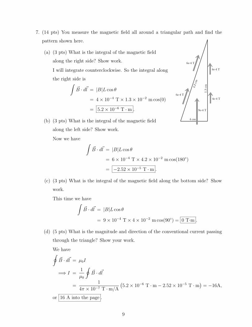
7. (14 pts) You measure the magnetic field all around a triangular path and find the
pattern shown here.
4 cm
1.3
cm4.2
cm
6e-4 T4e-4 T
9e-4 T
4e-4 T
6e-4 T
(a) (3 pts) What is the integral of the magnetic field
along the right side? Show work.
I will integrate counterclockwise. So the integral along
the right side is∫~B · d~l = |B|L cos θ
= 4× 10−4 T× 1.3× 10−2 m cos(0)
= 5.2× 10⁻⁶ T ·m .
(b) (3 pts) What is the integral of the magnetic field
along the left side? Show work.
Now we have ∫~B · d~l = |B|L cos θ
= 6× 10−4 T× 4.2× 10−2 m cos(180)
= −2.52× 10⁻⁵ T ·m .
(c) (3 pts) What is the integral of the magnetic field along the bottom side? Show
work.
This time we have∫~B · d~l = |B|L cos θ
= 9× 10−4 T× 4× 10−2 m cos(90) = 0 T·m .
(d) (5 pts) What is the magnitude and direction of the conventional current passing
through the triangle? Show your work.
We have∮~B · d~l = µ0I
=⇒ I =1
µ0
∮~B · d~l
=1
4π × 10−7 T ·m/A(5.2× 10−6 T ·m− 2.52× 10⁻⁵ T ·m
)= −16A,
or 16 A into the page .
9

8. (6 pts) Charged particles traveling through a bubble chamber leaves visible trails
behind them. A photograph taken in a bubble chamber showed the tracks of three
particles. The particles were traveling in the directions indicated by arrows on the
diagram, and there was a strong uniform magnetic field pointing out of the page
throughout the region.
On the diagram, identify the sign of the charge of each particle. Explain your reasoning
below, explicitly using arrows to represent velocity, field, and force vectors.
B throughoutregion
vF
vF
1
1
2
2
vF33
1
2
3
Using the right-hand rule,
• For particle 1: ~v1 × ~B will give ~F1 as shown for a negative charge .
• For particle 2: ~v2 × ~B will give ~F2 as shown for a negative charge .
• For particle 3: ~v3 × ~B will give ~F3 as shown for a positive charge .
10
Things you must know
Relationship between electric field and electric force Conservation of charge
Electric field of a point charge The Superposition Principle
Magnetic field of a moving point charge
Other Fundamental Concepts
∆Uel = q∆V ∆V = −∫ f
i
~E · d~l ≈ −Σ(Ex∆x+ Ey∆y + Ez∆z)
Φel =
∫~E · n dA Φmag =
∫~B · n dA∮
~E · n dA =
∑qinside
ε0
∮~B · n dA = 0
Ampere without Maxwell (no displacement current)∮~B · d~l = µ0
∑Iinside path
Specific Results
~E due to uniformly charged spherical shell: outside like point charge; inside zero
| ~Edipole, axis| ≈1
4πε0
2qs
r3(on axis, r s) | ~Edipole, ⊥| ≈
1
4πε0
qs
r3(on ⊥ axis, r s)
| ~Erod| =1
4πε0
Q
r√r2 + (L/2)2
(r ⊥ from center) | ~Erod| ≈1
4πε0
2Q/L
r(if r L)
Electric dipole moment p = qs | ~Ering| =1
4πε0
qz
(z2 +R2)3/2(z alongaxis)
| ~Edisk| =Q/A
2ε0
[1− z√
z2 +R2
](z alongaxis) | ~Edisk| ≈
Q/A
2ε0
[1− z
R
]≈ Q/A
2ε0(if z R)
| ~Ecapacitor| ≈Q/A
ε(+Q and−Q disks) | ~Efringe| ≈
Q/A
ε
( s
2R
)(just outside capacitor)
∆ ~B =µ0
4π
I∆~l × ~rr2
(shortwire)
| ~Bwire| =µ0
4π
LI
r√r2 + (L/2)2
≈ µ0
4π
2I
r(r L)
| ~Bloop| =µ0
4π
2IπR2
(z2 +R2)3/2≈ µ0
4π
2IπR2
z3(on axis, z R) µ = IA = IπR2
| ~Bdipole, axis| ≈µ0
4π
2µ
r3(on axis, r s) | ~Bdipole, ⊥| ≈
µ0
4π
µ
r3(on ⊥ axis, r s)
11
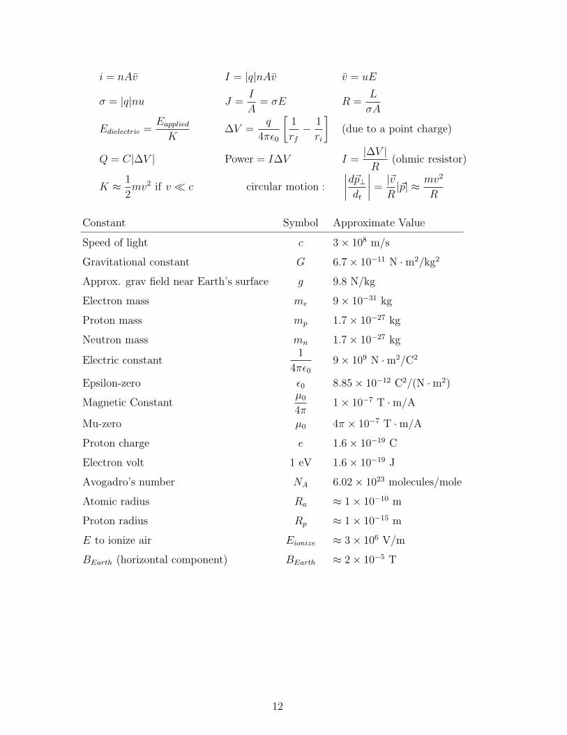
i = nAv I = |q|nAv v = uE
σ = |q|nu J =I
A= σE R =
L
σA
Edielectric =Eapplied
K∆V =
q
4πε0
[1
rf
− 1
ri
](due to a point charge)
Q = C|∆V | Power = I∆V I =|∆V |R
(ohmic resistor)
K ≈ 1
2mv2 if v c circular motion :
∣∣∣∣d~p⊥dt
∣∣∣∣ =|~vR|~p| ≈ mv2
R
Constant Symbol Approximate Value
Speed of light c 3× 10⁸ m/s
Gravitational constant G 6.7× 10⁻¹¹ N ·m2/kg2
Approx. grav field near Earth’s surface g 9.8 N/kg
Electron mass me 9× 10⁻³¹ kg
Proton mass mp 1.7× 10⁻²⁷ kg
Neutron mass mn 1.7× 10⁻²⁷ kg
Electric constant1
4πε09× 109 N ·m2/C2
Epsilon-zero ε0 8.85× 10⁻¹² C2/(N ·m2)
Magnetic Constantµ0
4π1× 10⁻⁷ T ·m/A
Mu-zero µ0 4π × 10−7 T ·m/A
Proton charge e 1.6× 10⁻¹⁹ C
Electron volt 1 eV 1.6× 10⁻¹⁹ J
Avogadro’s number NA 6.02× 10²³ molecules/mole
Atomic radius Ra ≈ 1× 10⁻¹⁰ m
Proton radius Rp ≈ 1× 10⁻¹⁵ m
E to ionize air Eionize ≈ 3× 10⁶ V/m
BEarth (horizontal component) BEarth ≈ 2× 10⁻⁵ T
12