Embed Size (px)
Citation preview
1
Düsseldorf, 15 – 19 June 2015
TEMPCORE®, the most convenient process to produce low cost high strength rebars from 8 to 75 mm J.F. Noville, Centre for Research in Metallurgy (CRM), Liège, Belgium Contact data Noville Jean-François, CRM Group – CRM, Avenue du Bois Saint-Jean, 21 (P59) B-4000 Liege – Belgium, Phone +32 4254 6425, Fax +32 4254 6444, [email protected] Summary Since its first industrial application 40 years ago, the Tempcore® process has become a very popular solution for producing high strength and weldable reinforcing concrete bars (rebars) from low C/Mn steel without requiring costly addition of V or Nb for most of the grades to produce. The Tempcore installation is in-line connected to the hot rolling mill, directly after the finishing stand. The three stages of the treatment are the quenching (intense cooling of the surface layer during a fixed time to obtain a controlled layer of martensite under the bar skin), the tempering of this martensite layer (through the heat released from the core of the rebar) and the transformation of the core from austenite into fine ferrite and perlite (+ bainite). To correctly apply the process, the tailor-made design of Tempcore cooling installation is of prime importance to meet the customer requests. This design is achieved by CRM on the basis of precise calculation and simulation tools, complemented by a very large expertise (more than 70 mills equipped around the world), taking into account the rolling data (dia, speed, finishing temperature, slit-rolling,…), the grades to produce, the mill layout, the specific mill constraints and the controllability of the process. Today, the Tempcore process is implemented in new or existing mills to produce economically the requested grades in a wide range of diameters. Up to 4 strands (slit-rolling) with individual cooling control per line has been designed for small diameters, as well as special development to preserve the cooling uniformity along the billet for large diameters up to 75 mm. Key Words Tempcore, high strength rebars, reinforcing concrete bars, quench and self-tempering, QST, thermal treatment, quenching, martensite. Introduction Since the beginning of the eighties years, the quench and self-tempering process (QST) has become an absolute must to produce weldable high strength reinforcing bars at low cost. Thus, this process has been introduced in hundreds of rolling mills, directly at the exit of their finishing stands. For new rolling mills, the length available for the quenching equipment between the last stand and the cooling bed is often high enough and a “standard” quenching device can be proposed by manufacturers with cooling lengths sometime twice longer than necessary and/or with unadapted water flow rate. For existing rolling mills, the situation is by far more complicated due to environment constraints (length and/or width available to introduce the quenching device) and sometime, the supplied equipment is not correctly adapted to the local production, leading to rolling speed reduction or addition of expensive micro-alloys to obtain the desired steel grade ! Moreover, even with a cooling machine correctly designed, its use (set-up and operating conditions) can be far from optimal.
In the design of quenching installation, there are several criteria to take into account to optimize its functioning and its controllability, allowing to meet the customer requirements. The tailor-made design of Tempcore installations able to meet all these specifications will be described as well as the correct way to use and control the process. Principle of the Tempcore process The Tempcore process has been thoroughly described in other publications [1][2][3]:
The rebar leaving the last stand of the hot rolling mill passes through a special water cooling section. The cooling efficiency of this installation is such that a surface layer of the bar is quenched into martensite, the core remaining austenitic. The quenching treatment is stopped when a determined thickness of martensite has been formed under the skin (outer part of the bar section dropping below the martensite transformation starting temperature Ms);

2
Düsseldorf, 15 – 19 June 2015
When the rebar leaves the intense cooling section, the temperature gradient established in its cross section causes heat to release from the centre to the surface. This increasing of the surface layer temperature results in the self-tempering of the martensite. The name TEMPCORE has been chosen to illustrate the fact that the martensitic layer is TEMPered by the heat left in the CORE at the end of the quenching stage;
Finally, during the slow cooling of the rebar on the cooling bed, the austenitic core transforms into ferrite and perlite or into bainite, ferrite and perlite.
The temperature time history of the rebar is shown in Figure 1.
Figure 1: Principle of Tempcore process The three stages of the Tempcore process clearly appear:
Quenching of the surface layer; Self-tempering of the martensite; Transformation of the core.
An important feature of the Tempcore process is its great versatility: for a given diameter and steel composition, the properties can be varied to a large extent by correctly choosing the duration of the first stage (cooling time) and the water flow in the quenching installation (intensity of cooling). Properly applied, the process allows an increase of the yield strength of 150-230 MPa without a prohibitive and significant decrease in ductility. High strength (weldable) grades & gain in steel composition Tempcore saves alloying elements for most of the high strength rebar standards over the world:
DIN488-IVS, BS4449:2005-B500, UNE36065:2000-B500SD, ASTM-A615-gr60, JIS-G3112-SD490, CNS-SD50, IS1786:2008-500D & 550D, AS4671:2001-500N, SANS920:2005, etc. This process is able to produce high strength weldable rebars with low carbon and low manganese contents [4]. No addition of costly micro alloying elements such as vanadium or niobium is necessary, saving today about 30-35 €/ton of product. Since the same billet composition can be used for different steel grades and diameters, a significant rationalization takes place in the plant. The water quenching and self-tempering treatment is applied directly in line after the finishing stand without any reduction of rolling speed or loss of productivity. By a judicious combination of Tempcore treatment and micro alloying chemistry, new higher grades (YS > 700 MPa, TS > 800 MPa) can be realized, especially for large diameters up to 75 mm. Tempcore tailor-made design Thanks to the experience on more than 70 installations designed and commissioned by CRM, two Tempcore models have been developed [5] and are continuously used and improved with new commissioning results. The first model is used for the design of installations. It computes the quenching time necessary to obtain the grade to produce (minimum yield strength, YS + safety margin) from the rebar data (diameter, finishing temperature), by selection of the internal diameter of cooling nozzles and the specific water flow rate:
The second model links the mechanical properties to the chemical composition of the steel:
with:
= quenching time (s) = rebar diameter (mm) T0 = rebar entry temperature (°C) YS = yield strength (MPa) TS = tensile strength (MPa) q = linear water flow rate (m³/h per m of line) F = filling coefficient, F= ²/ID² where ID = internal diameter of the cooling nozzle C = carbon content of the steel (%) Mn = manganese content of the steel (%) (K1, K2, a, b, c, d, e, α, β, γ, δ = constants)

3
Düsseldorf, 15 – 19 June 2015
When the rebar leaves the intense cooling section, the temperature gradient established in its cross section causes heat to release from the centre to the surface. This increasing of the surface layer temperature results in the self-tempering of the martensite. The name TEMPCORE has been chosen to illustrate the fact that the martensitic layer is TEMPered by the heat left in the CORE at the end of the quenching stage;
Finally, during the slow cooling of the rebar on the cooling bed, the austenitic core transforms into ferrite and perlite or into bainite, ferrite and perlite.
The temperature time history of the rebar is shown in Figure 1.
Figure 1: Principle of Tempcore process The three stages of the Tempcore process clearly appear:
Quenching of the surface layer; Self-tempering of the martensite; Transformation of the core.
An important feature of the Tempcore process is its great versatility: for a given diameter and steel composition, the properties can be varied to a large extent by correctly choosing the duration of the first stage (cooling time) and the water flow in the quenching installation (intensity of cooling). Properly applied, the process allows an increase of the yield strength of 150-230 MPa without a prohibitive and significant decrease in ductility. High strength (weldable) grades & gain in steel composition Tempcore saves alloying elements for most of the high strength rebar standards over the world:
DIN488-IVS, BS4449:2005-B500, UNE36065:2000-B500SD, ASTM-A615-gr60, JIS-G3112-SD490, CNS-SD50, IS1786:2008-500D & 550D, AS4671:2001-500N, SANS920:2005, etc. This process is able to produce high strength weldable rebars with low carbon and low manganese contents [4]. No addition of costly micro alloying elements such as vanadium or niobium is necessary, saving today about 30-35 €/ton of product. Since the same billet composition can be used for different steel grades and diameters, a significant rationalization takes place in the plant. The water quenching and self-tempering treatment is applied directly in line after the finishing stand without any reduction of rolling speed or loss of productivity. By a judicious combination of Tempcore treatment and micro alloying chemistry, new higher grades (YS > 700 MPa, TS > 800 MPa) can be realized, especially for large diameters up to 75 mm. Tempcore tailor-made design Thanks to the experience on more than 70 installations designed and commissioned by CRM, two Tempcore models have been developed [5] and are continuously used and improved with new commissioning results. The first model is used for the design of installations. It computes the quenching time necessary to obtain the grade to produce (minimum yield strength, YS + safety margin) from the rebar data (diameter, finishing temperature), by selection of the internal diameter of cooling nozzles and the specific water flow rate:
The second model links the mechanical properties to the chemical composition of the steel:
with:
= quenching time (s) = rebar diameter (mm) T0 = rebar entry temperature (°C) YS = yield strength (MPa) TS = tensile strength (MPa) q = linear water flow rate (m³/h per m of line) F = filling coefficient, F= ²/ID² where ID = internal diameter of the cooling nozzle C = carbon content of the steel (%) Mn = manganese content of the steel (%) (K1, K2, a, b, c, d, e, α, β, γ, δ = constants)
The optimization of each new Tempcore installation (well described by P. Simon [5]), takes into account the mill constraints, the rebar straightness and the controllability of the process, and supplies the best compromise between:
Overall length of the equipment; Total cooling water flow rate (at nominal
pressure of 12 bars); Number of ranges of cooling nozzles
required to cover the whole range of rebars diameters.
Another important point is to reduce the time and manpower required during changes in diameter or to produce non-Tempcore products. When the available space is sufficient, a laterally movable water collecting box is chosen (Figure 2).
Figure 2: Quick change of Tempcore cooling line For long cooling line, a segmentation in two or three water boxes (each individually laterally movable) is also possible as for this recent installation of 54 m for large rebars up to 75 mm diameter. It is divided in 3 sections of 18 m each (Figure 3) and equipped with remote ON/OFF valve on each cooling nozzle.
Figure 3: Longest Tempcore installation (3 x 18 m) When the available space (width, pass line level) is the main constraint, the water collecting box could be fixed with one range of cooling nozzles. Figure 4 shows such a case comprising additional constraints by the large roll shafts crossing the cooling box imposing to select correctly the length and repartition of cooling nozzles (no piping in shaft location,
accessibility of valves) and an efficient draining of water into the pit.
Figure 4: Tempcore design for a narrow space Another recent tailor-made Tempcore installation has been designed with 4 parallel cooling lines (slit-rolled diameters of 8 to 12 mm) in a compact stainless steel water collecting box, equipped on each strand with individual control of cooling length and water flow rate (Figure 5).
Figure 5: Tempcore design for slitting (4 lines) Some other specific features are also used such as:
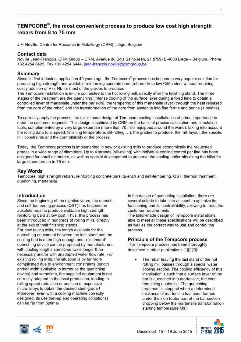
The protection of the un-used cooling nozzles against overheating (mainly at entry of the cooling line) by external full cone nozzles (Figure 2) or by means of water jackets along the downstream cooling tubes with water going by 2 full cone nozzles to cool the injector (Figure 6);
The anti-sucking device used in front of cooling nozzle (for rebar diameters from 25 mm) to prevent sucking of air by the nozzles and to avoid the corresponding decrease in
4
Düsseldorf, 15 – 19 June 2015
cooling efficiency at the front end of the billets (figure 6);
Figure 6: Cooling nozzle with anti-sucking device Control of the Tempcore process The control procedure is based on the Yield Strength/Tempering Temperature relationships obtained from the results of the commissioning trials. An example of such results is given for rebar of diameter 40 mm (Figure 7). It shows also clearly the variation of the thickness of martensite layer versus the yield strength. The cooling power of the quenching lines has to be adjusted in order to obtain the value required for the yield strength (YS from grade + safety margin). The pyrometers are the heart of the control of the process. The location of the tempering pyrometer is of prime importance to get measurements as close as possible to the maximum recovery temperature (maximum reached by the surface: Figure 1). The pyrometer located at the entry of the Tempcore box is also important to measure the variation of finishing temperature along the billet or between successive billets. A variation of 50°C of the finishing temperature corresponds to a variation of about 8% of the cooling length at equal specific water flow rate, and thus to variation of the tensile properties after treatment.
Figure 7: YS-Tempering temperature relationships The control of the cooling power of a Tempcore line is performed in two steps:
In the first step (main control), the length of the quenching line (i.e. the number of nozzles in use) is adjusted. In order to
perform an efficient control and to maintain a good homogeneity of the cooling, the nozzles to be switched off are the upstream ones.
In the second step (fine tuning), the water
flow rate is adjusted by acting on the main modulating valve.
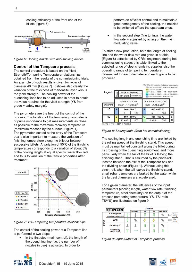
To start a new production, both the length of cooling line and the water flow rate are given in a table (Figure 8) established by CRM’ engineers during hot commissioning stage: this table, linked to the selected range of steel chemistry, supplies also the operating range of tempering temperature determined for each diameter and each grade to be produced.
Figure 8: Setting table (from hot commissioning) The cooling length and quenching time are linked by the rolling speed at the finishing stand. This speed must be maintained constant along the billet during its crossing of the quenching equipment, and more particularly when the tail of the billet is leaving the finishing stand. That is assumed by the pinch-roll located between the exit of the Tempcore box and the dividing shear (Figure 1). Without using this pinch-roll, when the tail leaves the finishing stand, small rebar diameters are braked by the water while the largest diameters are accelerated. For a given diameter, the influences of the input parameters (cooling length, water flow rate, finishing temperature, steel chemistry) on the output of the process (tempering temperature, YS, TS, ratio TS/YS) are illustrated on figure 9.
Figure 9: Input-Output of Tempcore process

5
Düsseldorf, 15 – 19 June 2015
cooling efficiency at the front end of the billets (figure 6);
Figure 6: Cooling nozzle with anti-sucking device Control of the Tempcore process The control procedure is based on the Yield Strength/Tempering Temperature relationships obtained from the results of the commissioning trials. An example of such results is given for rebar of diameter 40 mm (Figure 7). It shows also clearly the variation of the thickness of martensite layer versus the yield strength. The cooling power of the quenching lines has to be adjusted in order to obtain the value required for the yield strength (YS from grade + safety margin). The pyrometers are the heart of the control of the process. The location of the tempering pyrometer is of prime importance to get measurements as close as possible to the maximum recovery temperature (maximum reached by the surface: Figure 1). The pyrometer located at the entry of the Tempcore box is also important to measure the variation of finishing temperature along the billet or between successive billets. A variation of 50°C of the finishing temperature corresponds to a variation of about 8% of the cooling length at equal specific water flow rate, and thus to variation of the tensile properties after treatment.
Figure 7: YS-Tempering temperature relationships The control of the cooling power of a Tempcore line is performed in two steps:
In the first step (main control), the length of the quenching line (i.e. the number of nozzles in use) is adjusted. In order to
perform an efficient control and to maintain a good homogeneity of the cooling, the nozzles to be switched off are the upstream ones.
In the second step (fine tuning), the water
flow rate is adjusted by acting on the main modulating valve.
To start a new production, both the length of cooling line and the water flow rate are given in a table (Figure 8) established by CRM’ engineers during hot commissioning stage: this table, linked to the selected range of steel chemistry, supplies also the operating range of tempering temperature determined for each diameter and each grade to be produced.
Figure 8: Setting table (from hot commissioning) The cooling length and quenching time are linked by the rolling speed at the finishing stand. This speed must be maintained constant along the billet during its crossing of the quenching equipment, and more particularly when the tail of the billet is leaving the finishing stand. That is assumed by the pinch-roll located between the exit of the Tempcore box and the dividing shear (Figure 1). Without using this pinch-roll, when the tail leaves the finishing stand, small rebar diameters are braked by the water while the largest diameters are accelerated. For a given diameter, the influences of the input parameters (cooling length, water flow rate, finishing temperature, steel chemistry) on the output of the process (tempering temperature, YS, TS, ratio TS/YS) are illustrated on figure 9.
Figure 9: Input-Output of Tempcore process
Case of slit rolling: After the dividing shear located downstream the quenching equipment, there can be some twisting of the different strands. Therefore, it is not always possible to know which strand is measured at the tempering pyrometer location. To solve this problem, additional pyrometers (either one on each line or only one scanning pyrometer for all lines) will be installed at a place (“3” in Figure 10) where the different strands are still separated.
Figure 10: control of treatment for slit-rolling The measurements of these additional pyrometers are used to "balance" the water flow (measured by flowmeter) between the different lines by action on the corresponding balancing valves (Figure 11). This feature allows the operator to control and adjust the cooling power on each cooling line. This method ensures equal and uniform mechanical properties of rebars produced on each strand, even if some variations occur between the different slit-rebars (size, finishing temperature) or between the different cooling lines (clogging or wear of some nozzles …).
Figure 11: Balancing valves with flowmeters for slit-rolling Correct use of the Tempcore installation To obtain a homogenous treatment, the intensity of the cooling (given by the water flow rate per meter of line) must be high enough to obtain a complete and
regular martensite outer ring, constant along the billet.
Figure 12 shows the good results obtained during commissioning of diameter 75 mm).
Figure 12: Homogenity of rebar dia. 75 mm
The good straightness of the rebars is obtained with homogenous Tempcore treatment (Figure 13). If the martensite ring is open, wavy bars are observed on the cooling bed.
Figure 13: Straightness of slit-rebars dia 12 mm Here is a non-exhaustive list of what to not do:
Rebar of too small diameter treated through too large cooling nozzle: filling coefficient F is too low, leading to an open martensite ring.. That is also observed when the cooling nozzles present an excessive wear, often due to misalignment of these cooling nozzles!
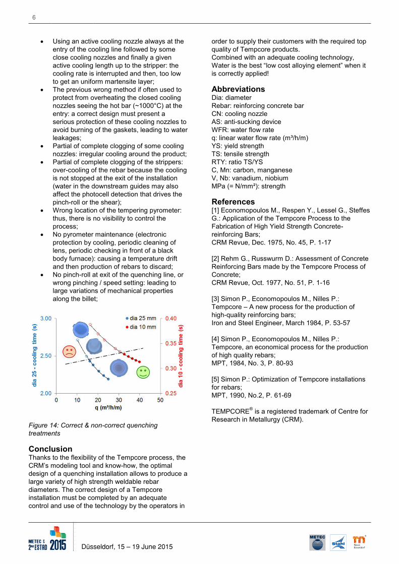
Using of the full cooling length available with low water flow rate per meter: cooling intensity is then too low (Figure 14 shows correct and bad treatments);
The previous method is more dramatic when the designed cooling length is more than twice the necessary one;
6
Düsseldorf, 15 – 19 June 2015
Using an active cooling nozzle always at the entry of the cooling line followed by some close cooling nozzles and finally a given active cooling length up to the stripper: the cooling rate is interrupted and then, too low to get an uniform martensite layer;
The previous wrong method if often used to protect from overheating the closed cooling nozzles seeing the hot bar (~1000°C) at the entry: a correct design must present a serious protection of these cooling nozzles to avoid burning of the gaskets, leading to water leakages;
Partial of complete clogging of some cooling nozzles: irregular cooling around the product;
Partial of complete clogging of the strippers: over-cooling of the rebar because the cooling is not stopped at the exit of the installation (water in the downstream guides may also affect the photocell detection that drives the pinch-roll or the shear);
Wrong location of the tempering pyrometer: thus, there is no visibility to control the process;
No pyrometer maintenance (electronic protection by cooling, periodic cleaning of lens, periodic checking in front of a black body furnace): causing a temperature drift and then production of rebars to discard;
No pinch-roll at exit of the quenching line, or wrong pinching / speed setting: leading to large variations of mechanical properties along the billet;
Figure 14: Correct & non-correct quenching treatments Conclusion Thanks to the flexibility of the Tempcore process, the CRM’s modeling tool and know-how, the optimal design of a quenching installation allows to produce a large variety of high strength weldable rebar diameters. The correct design of a Tempcore installation must be completed by an adequate control and use of the technology by the operators in
order to supply their customers with the required top quality of Tempcore products. Combined with an adequate cooling technology, Water is the best “low cost alloying element” when it is correctly applied! Abbreviations Dia: diameter Rebar: reinforcing concrete bar CN: cooling nozzle AS: anti-sucking device WFR: water flow rate q: linear water flow rate (m³/h/m) YS: yield strength TS: tensile strength RTY: ratio TS/YS C, Mn: carbon, manganese V, Nb: vanadium, niobium MPa (= N/mm²): strength References [1] Economopoulos M., Respen Y., Lessel G., Steffes G.: Application of the Tempcore Process to the Fabrication of High Yield Strength Concrete-reinforcing Bars; CRM Revue, Dec. 1975, No. 45, P. 1-17 [2] Rehm G., Russwurm D.: Assessment of Concrete Reinforcing Bars made by the Tempcore Process of Concrete; CRM Revue, Oct. 1977, No. 51, P. 1-16 [3] Simon P., Economopoulos M., Nilles P.: Tempcore – A new process for the production of high-quality reinforcing bars; Iron and Steel Engineer, March 1984, P. 53-57 [4] Simon P., Economopoulos M., Nilles P.: Tempcore, an economical process for the production of high quality rebars; MPT, 1984, No. 3, P. 80-93 [5] Simon P.: Optimization of Tempcore installations for rebars; MPT, 1990, No.2, P. 61-69 TEMPCORE® is a registered trademark of Centre for Research in Metallurgy (CRM).