Embed Size (px)
Citation preview

PHOTOVOLTAICS IN THE SMART GRID
Tamás Kerekes PhD
Department of Energy Technology
Aalborg University

Overview
Renewable energy 2011
PhotoVoltaics 2011
PV systems
Technical challenges
Conclusion
5-10-2012 Aalborg University: A One-Stop Shop to the Research on Smart-Grid Slide 2

European power capacity
Ref: Wind in power: 2011 European statistics, Feb. 2012
5-10-2012 Aalborg University: A One-Stop Shop to the Research on Smart-Grid Slide 3

New electricity installations in 2011
• In Europe 45GW of new electricity
generating capacity has been installed
• Solar PV installed 21,000 MW (46.7%
of total installed capacity in 2011)
• Gas installations have a share of 21.6%
• Wind installations 21.4%
Ref: Wind in power: 2011 European statistics, Feb. 2012
5-10-2012 Aalborg University: A One-Stop Shop to the Research on Smart-Grid Slide 4

Share of Renewable installations in 2011
• In Europe 32GW of renewable has
been installed in 2011
• New PV installations represent 66%
Ref: Wind in power: 2011 European statistics, Feb. 2012
5-10-2012 Aalborg University: A One-Stop Shop to the Research on Smart-Grid Slide 5

PV capacity worldwide
According to EPIA: According to IEA-PVPS:
• Worldwide 29GW of PV installed in 2011
• Total capacity up to almost 70GW of PV in the world at the end of 2011 Ref: EPIA and IEA-PVPS, 2012
5-10-2012 Aalborg University: A One-Stop Shop to the Research on Smart-Grid Slide 6

Grid-Connected PV systems Distributed Generation
5-10-2012 Aalborg University: A One-Stop Shop to the Research on Smart-Grid Slide 7

Grid-Connected PV systems
Power ConverterGrid
SunDC
AC
PV Generator Electrical Power
Source: PoweOne Ultra 1400; tomorrowisgreener.com; danfoss.com
Residential systems:
• up to 30kW
• connected to LV grid (400V)
Photovoltaic plants:
• several MW
• connected to MV grid (20kV)
5-10-2012 Aalborg University: A One-Stop Shop to the Research on Smart-Grid Slide 8
PV inverter structures
PV Strings
Central inverter
AC bus AC bus
String inverters
PV Strings
AC bus AC bus
Multi-string inverters
PV Strings
AC bus
5-10-2012 Aalborg University: A One-Stop Shop to the Research on Smart-Grid Slide 9
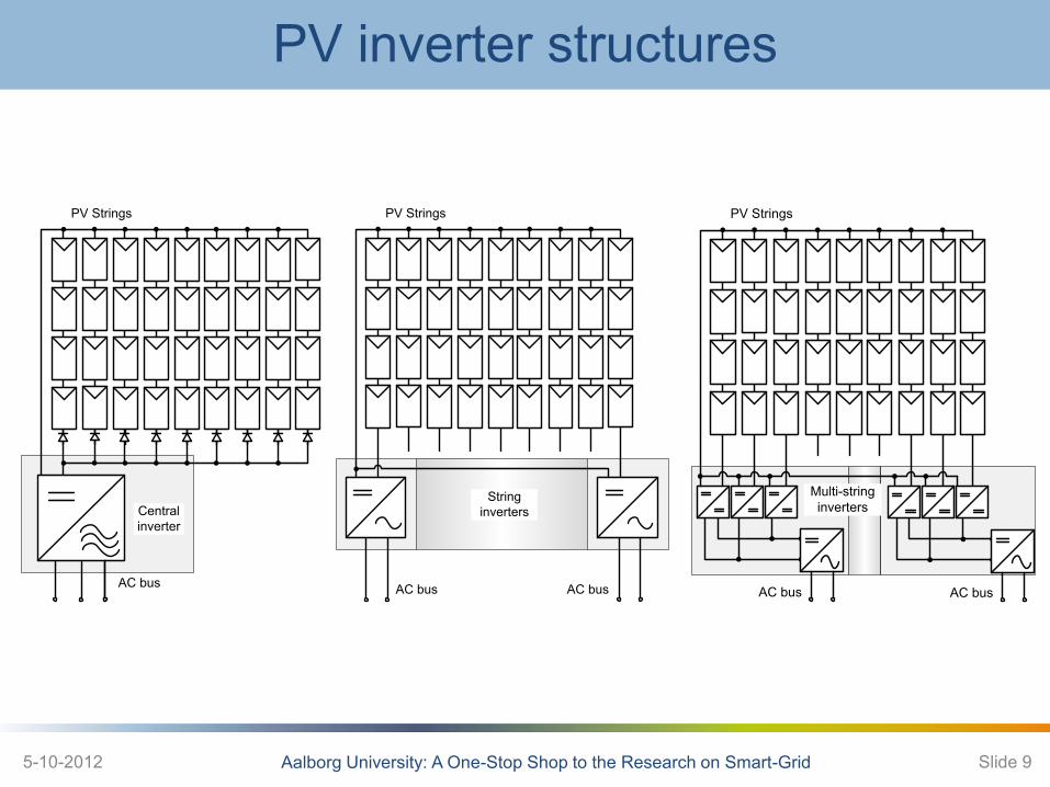
PV inverter structures: Central Inverters
• High Performance for Large PV Plant, High Level Monitoring ,
High Level Intelligence, Reliability
• High Efficiency (up 97%), Competitive prize/performance ratio.
• Typical structure – String inverter, 3-phase FB proven technology
(more parallel) with transformer to MV
• Manufacturers:
– Aero Sharp, Aros (Sirio), Conergy, Control Techniques, EEI - Equipaggiamenti
Elettronici Industriali Srl, Eurener, Green Power, Helios System, Hyunday
Heavy, Integral Drive Systems AG, Ingeteam, Jema, Kaco, Layer, Leonics, Lti,
Padcon, Pairan, Power One, PV Powered, Refu, Elettronica Santerno, SatCon,
Schneider Electric, Siel, Siemens, Siliken, SMA, Sputnik, Voltwerk, Zigor
Central Inverter
Power FlowDC
Connection
Grid SideAC
Connection
PV INVERTERPV Generator
Data Flow
Data Flow
3-phaseTransformer
MEDIUMVOLTAGE
Monitoring Center
ABB – PVS800 • Multi-level achieved by dual inverter
configuration
• 100-500 kW
• 450-750Vdc input
• 400Vac out
• Efficiency > 97.5%
• Modular design, Long life-time,PF Comp
5-10-2012 Aalborg University: A One-Stop Shop to the Research on Smart-Grid Slide 10

Structures: Central Inverters -Learn from Wind Power
• 690VAC is standard in the wind industry
• Standard-components for up to 3MW + are cost-effective and reliable
• Inverter cost (approx.) proportional to AC current
• Up to 1500VDC is enabled for PV components by DIN VDE0100
• Reduces installation time
• Reduces copper costs and cabling losses
• Nominal power: 333kW @
3AC690V+N
• Max. efficiency:>98,5% with
UltraEta®topology
• MPP voltage range: 600-1200VDC
• Max. DC Voltage: 1400V
• Weight: approx. 400kg (1,20kg/kW)
• Outdoor-qualified housing
5-10-2012 Aalborg University: A One-Stop Shop to the Research on Smart-Grid Slide 11

Structures: Central Inverters
Efficient • Without low voltage transformer Higher system
efficiency due to direct connection to the medium
voltage Grid
Turnkey Delivery • With medium-voltage transformer and concrete
substation for outdoor installation
Optional • Grid management
• Control of reactive power
• Medium-voltage switching stations for a flexible
structure of large solar parks
• AC transfer station with measurement
• Medium-voltage transformers for other grid
voltages (deviating from 20 kV)
SUNNY CENTRAL up to 1250MV (2x Sunny Central 630HE)
5-10-2012 Aalborg University: A One-Stop Shop to the Research on Smart-Grid Slide 12

Structures: Central Inverters
Economic • Direct deployment in the field due to outdoor enclosure
• Simplified shipping without concrete substation
Efficient • Full nominal power at ambient temperatures up to 50 °C
• 10 % additional power for constant operation at ambient
temperatures up to 25 °C
• Max. efficiency: 98.6 % (w/o internal power supply)
• Euro ETA: 98.4 %
Flexible • Powerful grid management functions (including LVRT)
– Remote controlled power reduction in case of grid overload
– Frequency-dependent control of active power
– Static voltage support based on reactive power
– Dynamic Grid Support
• DC voltage range configurable
Reliable
• Easy and safe installation due to a separate connection area
• Optional: extended input voltage range up to 1,100 V
SUNNY CENTRAL 800CP (up to 800kVA)
5-10-2012 Aalborg University: A One-Stop Shop to the Research on Smart-Grid Slide 13

Voltage Rise and Overloading Problems 1. What constraints are more influential on LV networks ? 2. What is the most effective solution ?
Critical networks
Rural networks
Available space for PV installation
Load density
Suburban networks
Urban networks
• Low load density • Higher areas for PV installation • Longer distances to the substation
• High load density • Limited and common areas for PV installation • Short distances to the substation
5-10-2012 Aalborg University: A One-Stop Shop to the Research on Smart-Grid Slide 14 Ref: Erhan Demirok, AAU

Simulation Study
Low voltage (230/400V) Radial Feeder Model
Grid Dyn5, 1:1Rp,Rs
Lp,Ls
PV1 PV2
0.4 kVRg,Lg
R, L R, L R, L
PV3
R1, L1
PV4
R, L
PV7
R1, L1
PV8
R, L
PV11
Transformer
Grid resistance Rg 0.034 ohm
Grid inductance Lg 0.5 mH
Transf. Primary and secondary resistance Rp, Rs 0.5 ohm
Transf. primary and secondary leak. inductance Lp, Ls 1 mH
Line resistance R 0.025 ohm
Line inductance L 0.04 mH
Line resistance R1 0.25 ohm
Line inductance L1 0.4 mH
Radial feeder simulation parameters
11 inverters
Average inverter model
SOGI PLL
Fixed DC voltage at 700 V
Stationary-frame proportional-resonant digital
current controller
5-10-2012 Aalborg University: A One-Stop Shop to the Research on Smart-Grid Slide 15 Ref: Erhan Demirok, AAU
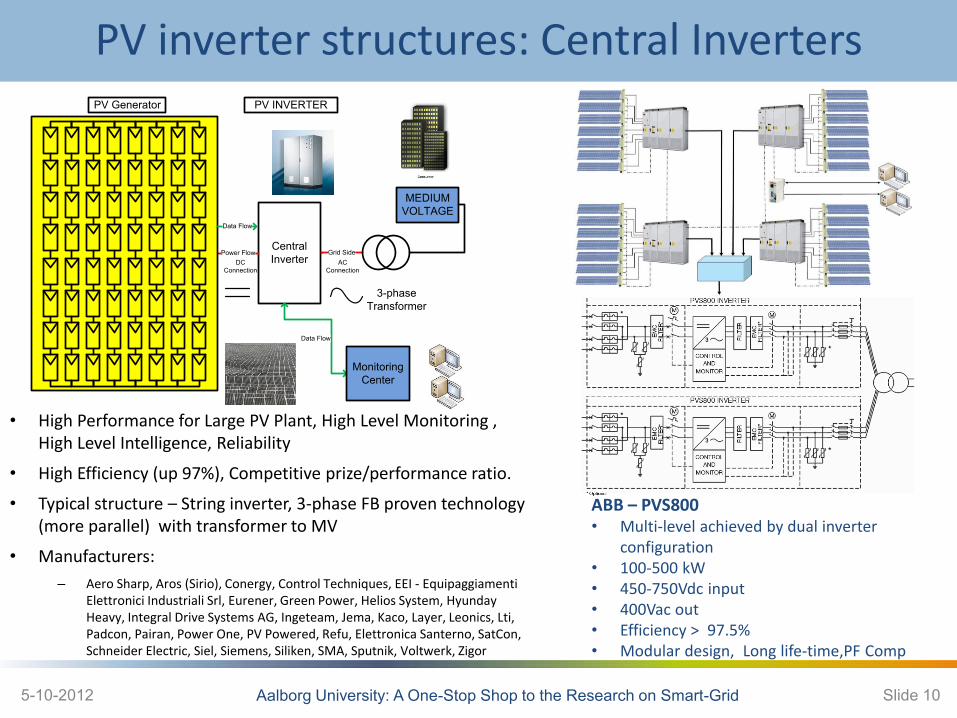
Braedstrup Grid Model
Trafo
PV60
PV1
Loop lines
Grid characteristics
Type of network suburban
Type of settlement residential
Number of houses 60
Type of houses Detached, single- or two-family
Transformer rated power 400 kVA
Grid topology radial for the simulation, meshed in real
Average distance between transformer and houses 415.5 m
Feeder cable types Al 3x240, Al 3x150, Al 3x95 mm2 (simulation), underground
Service cable types (between houses and feeder connection points) Al 50 mm2 underground
TABLE I
Summary of The Grid Characteristic
5-10-2012 Aalborg University: A One-Stop Shop to the Research on Smart-Grid Slide 16 Ref: Erhan Demirok, AAU

Braedstrup Grid Model
PV60
transformer
PV1
loop lines
5-10-2012 Aalborg University: A One-Stop Shop to the Research on Smart-Grid Slide 17
LVGridP
MV Grid
U
Length
ΔU
Q Q P Q P
ΔU
Qinductive
P max
P
φ
Qcapacitive
Plim
Qmax
S max
Ref: Erhan Demirok, AAU
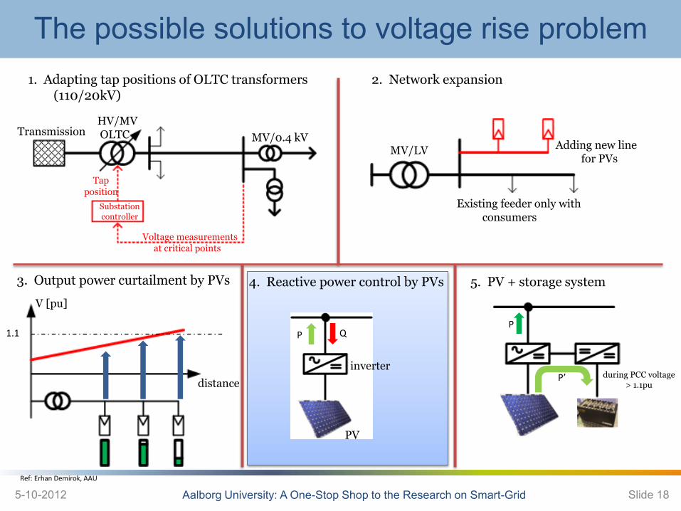
The possible solutions to voltage rise problem 1. Adapting tap positions of OLTC transformers
(110/20kV) 2. Network expansion
3. Output power curtailment by PVs
Existing feeder only with consumers
Adding new line for PVs
MV/LV
Voltage measurements at critical points
Tap position
HV/MV OLTC Transmission MV/0.4 kV
Substation controller
V [pu]
distance
1.1
4. Reactive power control by PVs
P Q
5. PV + storage system
PV
inverter
P
P’ during PCC voltage > 1.1pu
5-10-2012 Aalborg University: A One-Stop Shop to the Research on Smart-Grid Slide 18 Ref: Erhan Demirok, AAU

State-of-the-art Reactive Power Control (RPC) Methods
0.0
Q/Pn (%)
U (p.u.)
Q/Pn (%)
PV noPV1 PV2 PV3 PV4
PV3
PV4
PV1
closer to the transformer
PV2
1.0
cosφ
P/Pn (p.u.)PV1 PV2 PV3 PV4
PV1-PV4
closer to the transformer
cosφ
0.9
1.0
proposedstandard
proposedstandard
Main drawbacks of P dependent Q control methods:
• Absorbing unnecessary reactive power when the
produced real power is consumed locally and the
grid voltage is in the admissible range
• Voltage sensitivities are not taken into
consideration. The inverters with the leas voltage
sensitivity and with the highest voltage sensitivity
may utilize the same amount of Q.
Drawback of U dependent Q control methods:
• The inverters closer to the transformer may not
react to the overvoltage emergency condition that
is occurred at the end of feeders.
Following modifications are proposed:
• Power factor level of the nearest inverters to the transformer is increased at certain amounts for fixed cosφ and cosφ(P) methods
• Reactive power amount of the inverters nearest to the transformer is forced to be higher for Q(U) method.
5-10-2012 Aalborg University: A One-Stop Shop to the Research on Smart-Grid Slide 19 Ref: Erhan Demirok, AAU

Grid Interface Requirements - LV
PhotoVoltaic Power System - PVPS Course, Aalborg University 5-Oct-12 20
Voltage Deviations
IEEE 1574 IEC 61727 VDE 0126-1-1
Voltage range (%)
Disconnection
time (sec)
Voltage range
(%)
Disconnection
time (sec)
Voltage range
(%)
Disconnection
time (sec)
V < 50 0.16 V < 50 0.10 V < 85 0.20
50 ≤ V < 88 2.00 50 ≤ V < 85 2.00 V ≥ 110 0.20
110 < V < 120 1.00 110 < V < 135 2.00
V ≥ 120 0.16 V ≥ 135 0.05
Obs. The purpose of the allowed time delay is to ride through short-term disturbances to avoid
excessive nuisance tripping (LVRT)
VDE 0126-1-1 VDE-AR-N 4105 Voltage range
[Hz] Disconnection time
[s]
Voltage range
[Hz]
Disconnection time
[s]
V < 85
V ≥ 110 0.20
V < 80
V ≥ 110 0.10
VDE 0126-1-1 VDE-AR-N 4105
Frequency range [Hz] Disconnection time
[s] Frequency range [Hz]
Disconnection time
[s] 47.5 < f < 50.2 0.20 47.5 < f < 51.5 0.10

LVRT for PV inverters
Aalborg University: A One-Stop Shop to the Research on Smart-Grid 5-10-2012 Slide 21
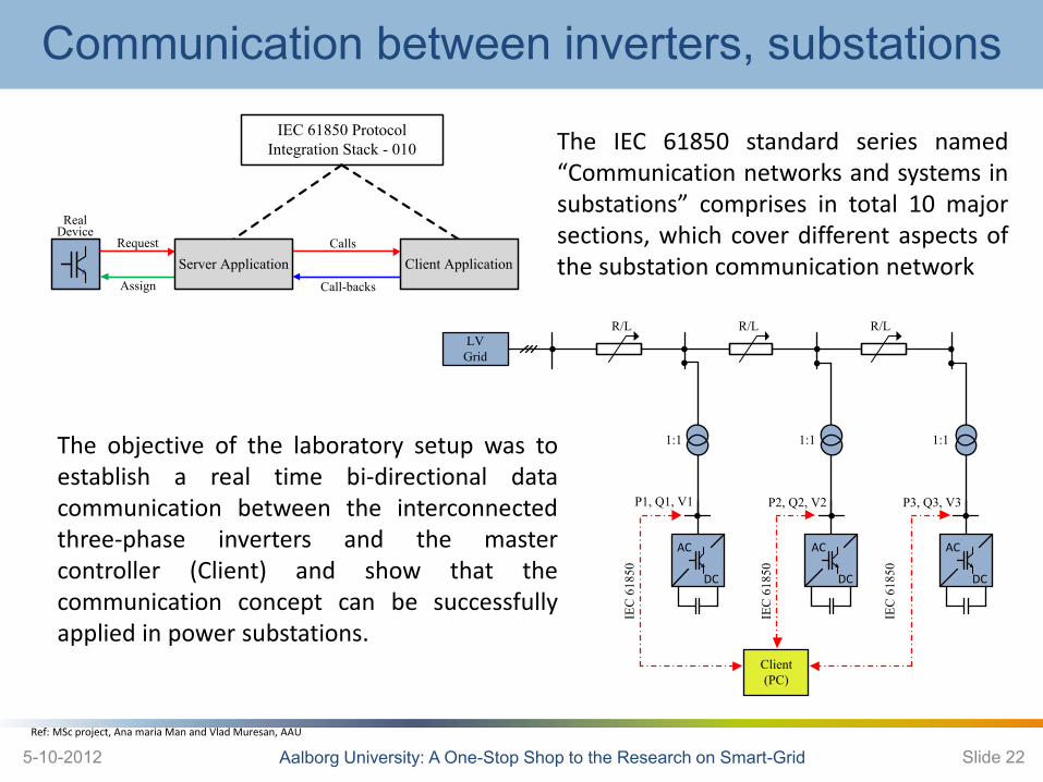
Communication between inverters, substations
Aalborg University: A One-Stop Shop to the Research on Smart-Grid 5-10-2012 Slide 22
IEC 61850 Protocol Integration Stack - 010
RealDevice
Request
Assign
Calls
Call-backs
Server Application Client Application
LVGrid
R/L R/L R/L
AC
DC
AC
DC
AC
DC
Client(PC)
P2, Q2, V2P1, Q1, V1
IEC
618
50
IEC
618
50
IEC
618
50
P3, Q3, V3
1:1 1:1 1:1The objective of the laboratory setup was to
establish a real time bi-directional data
communication between the interconnected
three-phase inverters and the master
controller (Client) and show that the
communication concept can be successfully
applied in power substations.
Ref: MSc project, Ana maria Man and Vlad Muresan, AAU
The IEC 61850 standard series named
“Communication networks and systems in
substations” comprises in total 10 major
sections, which cover different aspects of
the substation communication network

Conclusion
• PV systems have had a significant increase in the last years
• Around 70GW of PV installed worldwide
• High PV penetration can become a challenge for LV grid operators, but solutions are there to overcome these limitations
• Grid support from PV inverters (Q and LVRT)
• Communication between inverters is a requirement in case of a Smart Grid
5-10-2012 Aalborg University: A One-Stop Shop to the Research on Smart-Grid Slide 23
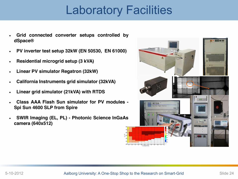
Laboratory Facilities
Aalborg University: A One-Stop Shop to the Research on Smart-Grid 5-10-2012 Slide 24
Grid connected converter setups controlled by dSpace®
PV inverter test setup 32kW (EN 50530, EN 61000)
Residential microgrid setup (3 kVA)
Linear PV simulator Regatron (32kW)
California Instruments grid simulator (32kVA)
Linear grid simulator (21kVA) with RTDS
Class AAA Flash Sun simulator for PV modules - Spi Sun 4600 SLP from Spire
SWIR Imaging (EL, PL) - Photonic Science InGaAs camera (640x512)

PhD/Industrial Courses - 2013
Aalborg University: A One-Stop Shop to the Research on Smart-Grid 5-10-2012 Slide 25
Power Electronics for Renewable Energy Systems - in Theory and Practice (3 days)
Photovoltaic Power Systems - in Theory and Practice (3 days)
AC Microgrids - in Theory and Practice (2 days)
DC Microgrids- in Theory and Practice (2 days)
Power Quality in Microgrids - in Theory and Practice (2 days)
Communications for Microgrids - in Theory and Practice (2 days)