Embed Size (px)
Citation preview

Photonic tractor beams: a reviewWeiqiang Ding,a,* Tongtong Zhu,a,b Lei-Ming Zhou,b and Cheng-Wei Qiub,*aHarbin Institute of Technology, Department of Physics, Harbin, ChinabNational University of Singapore, Department of Electrical and Computer Engineering, Singapore
Abstract. Usually, an unfocused light beam, such as a paraxial Gaussian beam, can exert a force on an objectalong the direction of light propagation, which is known as light pressure. Recently, however, it was found thatan unfocused light beam can also exert an optical pulling force (OPF) on an object toward the source direction;the beam is accordingly named an optical tractor beam. In recent years, this intriguing force has attracted muchattention and a huge amount of progress has been made both in theory and experiment. We briefly reviewrecent progress achieved on this topic. We classify the mechanisms to achieve an OPF into four different kindsaccording to the dominant factors. The first one is tailoring the incident beam. The second one is engineeringthe object’s optical parameters. The third one is designing the structured material background, in which thelight–matter interaction occurs, and the fourth one is utilizing the indirect photophoretic force, which is related tothe thermal effect of light absorption. For all the methods, we analyze the basic principles and review therecent achievements. Finally, we also give a brief conclusion and an outlook on the future development ofthis field.
Keywords: optical pulling force; optical tractor beam; optical manipulation; Bessel beam; nanophotonic structures; photophoresis;photophoretic force.
Received Oct. 12, 2018; accepted for publication Feb. 27, 2019; published online Mar. 27, 2019.
© The Authors. Published by SPIE and CLP under a Creative Commons Attribution 4.0 Unported License. Distribution orreproduction of this work in whole or in part requires full attribution of the original publication, including its DOI.
[DOI: 10.1117/1.AP.1.2.024001]
1 IntroductionSince the pioneering works by Ashkin,1–3 optical manipulationutilizing the mechanical effect of light has developed exten-sively in various contexts. Optical tweezers and other relatedmanipulation technologies have become indispensable invarious disciplines, including biology,4–7 chemistry,8 quantumscience and technology,9–11 and nanotechnology.12–14 One re-markable trend amid this progress is that optical manipulationhas been extended, from the initial single freedom of trappingusing the conservative optical force, to multiple freedoms usingboth conservative and nonconservative forces,15 including push-ing,16 pulling,17 lateral shifting, rotating,18–21 and spinning.22
Among all the newly developed manipulation freedoms,optical pulling is one of the most interesting and has attractedmuch attention,23–26 due to the potential applications and in-triguing physics behind it. Usually, when illuminated by atightly focused beam, the intensity gradient resorting force canovercome the scattering force, and the object can be trappednear the focus spot.2 On the other hand, when illuminated by
an unfocused beam, the intensity gradient force vanishes andthe object is expected to be pushed away.1 However, about10 years ago, researchers found that the object may experiencean optical pulling force (OPF) toward the source direction whenilluminated by an unfocused beam, such as a diffraction-free(nondiffraction) Bessel beam,27,28 which is named an opticaltractor beam (OTB). Although it seems counterintuitive, OPFhas been theoretically proved and experimentally demonstratedwithin recent years, as will be reviewed in this paper.
The pulling force by a single beam was first noticed byMarston in acoustics,29,30 who found that the axial radiation forceof a Bessel acoustic beam on a sphere could be inverted (frompushing to pulling) for some carefully designed objects, whichsuppressed the scattering to the back hemisphere. Since theacoustic and optical waves share many common features,it is not surprising to find pulling force in optics using similarmethods. Shortly after Marston, optical pulling phenomenawere predicted by Lee et al.24 in an optical solenoid beam, whichis a diffractionless beam with in-plane intensity peak spiralsaround the optical axis. In the same year, the concept of OTBwas confirmed by Sukhov and Dogariu.26 Following, anothertwo theoretical works published independently by Chen et al.27
*Address all correspondence toWeiqiang Ding, E-mail: [email protected]; Cheng-Wei Qiu, E-mail: [email protected]
Review Article
Advanced Photonics 024001-1 Mar∕Apr 2019 • Vol. 1(2)

and Novitsky et al.28 gave a clear analysis of the criteria andmethod to obtain an OPF. Since then, the OTB began to attractmore and more attention due to the interesting phenomena andphysics involved and possible applications in optical manipula-tion technology. What is more, the concept of OTB and pullingforce has been extended to other forms of wave, includingthe water wave31 and quantum matter wave,32 which are beyondthe scope of this paper.
Here we would like to make a clear and consistent definitionof the OPF. Usually, pulling means that the object moves against(or the force is reverse to) the direction of light propagation.However, the “direction of light propagation” is ambiguous insome cases since the directions of wavevector and Poyntingvector may be different, especially in structured optical beamsand nanostructures related to OPF. Due to this reason, in thispaper, OPF is defined relative to the relative position of the opticalsource and object, as shown in Fig. 1(a). Suppose the source islocated at A and the object is at B, then the center-to-center vectorAB (the blue dashed arrow) defines the axis of the force. Thepulling force means that the angle θ between the optical forceF (the thick red arrow) and the axis AB is larger than π∕2, asshown in Fig. 1(a). In this case, the projection of optical forceonAB is directed from B to A. On the contrary, the pushing forcemeans that the force projection is from A to B, or θ < π∕2. Sincethe relative position of the source and object can be determinedexplicitly, this definition is reasonable and acceptable.
In this work, we aim to make a brief review on the progress-ing topic of OPF. From the viewpoint of linear momentumconservation, in order to get an OPF, the effective forwardmomentum of the incident light should be enhanced when scat-tered by the object. Due to this reason, many works in this topicare about tailoring the momentums of light beams when they
impinge on and are scattered by the object using various me-chanics. In order to make this review clear and easy to follow,we classify the mechanisms of OPF into four kinds based onthe predominant factor in the pulling process, as shown inFigs. 1(b)–1(d). The first one is using structured beams, the sec-ond is using objects with exotic structures and parameters, thethird one is using a structured background that supports specialmodes, and the last one is using the photophoretic force thatresults from light absorption. Certainly, this classificationmethod is not rigorous and not unique, because in some casesmore than one effect is involved simultaneously.
Before discussing OPF, we would like to address the theo-retical and numerical methods used to investigate the OPF.Basically, the calculation methods of OPF are exactly the sameas those used in optical trapping.15 For objects much smallerthan the wavelength of the trapping light, dipole approximationcould be used to obtain analytical formulas for the opticalforces,33 from which the OPF can be identified. In this case,the outstanding angular scattering features of magnetic or largerdielectric particles determine the direction of the optical force,and the Kerker scattering conditions are useful in exploring theOPF.34–36 For objects much larger than the wavelength, the raytracing method could be used to calculate the optical forces.37,38
For the objects with moderate size comparable to the wave-length, an integration of Maxwell’s stress tensor on a closedsurface surrounding the object is necessary to calculate theoptical force,39 and some numerical simulation methods, suchas the finite-difference time-domain method or finite-elementmethods, are typically used to obtain the electromagnetic fieldsaround the object. Since those methods can be found easily inthe literature, we will skip these detailed methods, and readersmay refer to the references when necessary.
Fig. 1 (a) Definition of the OPF used in this paper. The source and object are centered at A and B,respectively, and the center-to-center vector AB (dashed blue) defines the pulling or pushing forceaxis. When the angle θ between the optical force F (the black thick arrow) and the axis AB is largerthan π∕2, the force is a pulling one. The special case of θ ¼ π is the most desirable in practice.When θ is less than π∕2, the force is a pushing one and the special case of θ ¼ 0 is widelyinvestigated in practice. (b)–(e) Four different mechanisms for achieving the OPF, where thespecial case of θ ¼ π is shown for clarity and S shows the energy flow. OPF (b) using structuredlight beams, (c) using objects with exotic optical parameters, (d) using structured backgroundmedia, and (e) using the photophoresis effect.
Ding et al.: Photonic tractor beams: a review
Advanced Photonics 024001-2 Mar∕Apr 2019 • Vol. 1(2)

2 Optical Pulling Force Achieved byStructured Beams
Using a structured light beam beyond the plane wave and theparaxial Gaussian beam is the first method proposed for achiev-ing OPF.24 There are several different specific configurationsin this mechanism. The first one is using a single-structureddiffraction-free beam, such as the Bessel beam and solenoidbeam. The second one is using the interferences of two or morestructured waves, such as two Bessel beams, two Gaussianbeams, or multiple plane waves.
2.1 Optical Pulling by a Single-Structured Beam
Lee et al.24 found a diffraction-free solution for the Helmholtzequation, i.e., the optical solenoid beam, in which the principalintensity peak spirals around the optical axis and its wavefrontare characterized by an independent helical pitch, as shown inFig. 2(a1). In this beam, the intensity gradient force traps a smallobject to the maximum intensity, whereas the scattering forcecan drive the object around the spiral, which is determined bythe phase gradient force.41 When the wavefront’s pitch relativeto propagation direction is tuned from forward to retrograde,OPF will be obtained. Finally, the combination of those twoforces pulls the object to the source direction, as indicated bythe experimental demonstration depicted in Fig. 2(a3). Anothersimilar helical tractor beam was also reported by Carreteroet al.42
Another kind of structured beam for generating an OPF is theBessel beam,27,28,43 which is also diffraction-free within a limited
region in propagation. Different from the solenoid beam, theintensity peak in this beam is along a straight line, which canbe obtained using an axicon44 or an optical metasurface.45,46
When a properly designed particle is illuminated by such abeam, multipoles (not only the dipole) may be excited simulta-neously, and the interferences between them can maximize theforward scattering while suppressing the backward scattering.27,40
Finally, the net linear momentum propagation along the direc-tion of propagation is increased, and in turn the object is recoiledtoward the light source, as shown in Fig. 2(b). For some valuesof particle size, the pulling is stable for a transparent and lossyobject, marked by the thick black curve in Fig. 2(b).
The pulling force can also be understood from the directionof the wavevector of Bessel beams.28 A Bessel beam can be re-garded as the superposition of a series of plane waves, in whichthe wavevectors lie on a cone with an apex angle α relative tothe propagation direction (such as the z axis), as shown inFig. 2(c1). When scattered by a carefully designed object, thewavevector kmay be realigned forcedly to the z direction due tothe scattering of the object. Since the amplitude of k is related tothe linear momentum of photons, the momentum projectionalong the z direction is enhanced, and the extra momentumsare balanced by the backward force on the object, as shown inFigs. 2(c2) and 2(c3). What is more, the transverse stability isalso guaranteed in this configuration, due to the restoring inten-sity gradient force provided by the Bessel beam.
One disadvantage of using a Bessel beam to generate OPF isthe sensitivity to the object size and optical parameters of theobject, perturbation of which may disturb or even destroy theoptical traction completely. (Certainly, this feature is also quite
Fig. 2 OPF by structured light beams: (a) experimental demonstration of OPF by a solenoidbeam:24 (a1) the spiral intensity peak pattern in experiment, (a2) wave vector back down the spiral,and (a3) experimental measurement of the pushing and pulling trace. (b) Theoretical proposal ofOPF achieved by the excitation of multipoles in the object,27,40 and (c1) theoretical proposal of OPFby a Bessel beam with a cone angle of α. (c2) and (c3) OPF changes with the relative permittivityand permeability of the object.28
Ding et al.: Photonic tractor beams: a review
Advanced Photonics 024001-3 Mar∕Apr 2019 • Vol. 1(2)

useful, such as in particle sorting, since the pulling force is sizeand optical parameters dependent.27,28) In order to overcome thisshortcoming, Novitsky et al.43 proposed universal criteria for thematerial-independent or size-independent OTB and found that thenonparaxial Bessel beam is an excellent candidate for this kind ofrobust tractor beam. Pfeiffer and Grbic47 reported an interestingmethod to realize the needed Bessel beam using a practical meta-surface. The designed silicon metasurface can convert the linearlypolarized Gaussian beam into the superposition of transverse-electric and transverse-magnetic polarized Bessel beams, whichcan stably pull a polystyrene sphere within the diffraction-freerange. Recently, the core–shell structure was proved to have po-tential power in the tailoring of light scattering,48,49 and thus it isalso used in the generation of enhanced OPF, even in the Rayleighregion using Bessel beams, which is also transversely stable.50
Also a cylindrical shape of dielectric particles can effectivelymitigate the nonparaxiality requirements to the Bessel beam.51
A more comprehensive analysis of stable pulling by a Besselbeam is provided in Ref. 52. Interestingly, except for cylindricalobjects, other kinds of elongated objects, such as opticallybound particles, can also be used to enhance the OPF.53,54
2.2 Optical Pulling by Interferences of Multiple Beams
Although a single-structured beam can act as a tractor beam,multiple beams cooperating together can make the OPF more
flexible. In the supplementary materials of Ref. 27, Chen et al.theoretically proposed that two plane waves are possible to pullsome small object. Later, Sukhov and Dogariu55 theoreticallyproposed the general mechanism to realize optical pulling forarbitrary objects using multiple plane waves. The method isto launch a series of plane waves (such as 24 waves) propagatingalong a cone surface (with the apex angle of θ ¼ 84 deg) withthe same amplitude but optimized relative polarizations andphases, as shown in Fig. 3(a). In this scheme, all the plane wavecomponents have the same longitudinal wavevector, thus form adiffraction-free beam suitable for long-range pulling. For the op-timized incident waves, a pulling force of −0.24 pN is obtained.Actually, this latter method based on multiple-plane wave inter-faces is more powerful and could be optimized to get an almostarbitrary scattering pattern and various kinds of optical forces,such as the transverse optical force.
While the multiple-plane wave interference method is power-ful, handling so many waves is not easy in practice. Is it possibleto get an OPF using fewer waves? Brzobohatý et al.54 theoreti-cally proposed and experimentally demonstrated the OPF on apolystyrene particle with a radius of 410 nm using two Gaussianbeams, or using one Gaussian beam and a reflection mirror, asshown in Fig. 3(b). The key point in this geometry is the largeangle between the two incident waves (the angle between wave-vector k1 and k2 ranges from 152 deg to 180 deg), which makesthe majority of the beam scatter in a forward direction for
Fig. 3 OPF by the interference of multiple beams. (a) Using the interference of a series of planewaves,55 and (b) using the interference of two Gaussian beams:54 (b1) schematic illustration of theconfiguration, (b2) the s-polarization can get forward scattering enhancement, and thus a pullingforce, and (b3) the p-polarization cannot. (c) OPF using the interference of two codirectionalBessel beams:56 (c1) schematic illustration of the Bessel beam by an SLM and a lens, (c2) volu-metric reconstruction of the Bessel beam, (c3) phase hologram encoding the optical conveyor, and(c4) volumetric reconstruction of the beam projected by the hologram in (c3).
Ding et al.: Photonic tractor beams: a review
Advanced Photonics 024001-4 Mar∕Apr 2019 • Vol. 1(2)

s-polarization. When the transverse forces are cancelled witheach other, a final net force is left reverse to the direction ofk1 þ k2, i.e., an OPF. For the p-polarization, however, the forceis always pushing. Since the direction of the force is size-depen-dent and polarization-dependent, this method is also efficient inparticle sorting and can be switched by polarization.
Another mechanism for OPF achieved by Ruffner et al.54
seems more flexible, as shown in Fig. 3(c). The directions ofthe particle could be tuned actively and it behaves as an opticalconveyor.57,58 They launched two coherent Bessel beams alongthe same direction with slightly different longitudinal wavevec-tors and tunable relative phases, and an active tractor beam wasobtained. Since the wavevectors of the two beams are different,a series of intensity peaks are obtained, and thus a particle couldbe trapped by the intensity gradient force. Then by tuning therelative phases ϕðtÞ of the two beams, the positions of the peakscould shift forward or backward, and the trapped object can betransported upstream or downstream. Actually, this principle hasbeen investigated by Cižmár59 for submicron particle organizationand bidirectional shift. Basically, this method is a little differentfrom those mentioned above, because the scattering is not the keyissue in this case, but the shift of the trapping center.57,60
3 Optical Pulling Force Achieved byExotic Object Parameters
3.1 Optical Pulling Force by Optical Gain and Loss
Except for using one or more structured light beams, OPF isalso possible to achieve using an object with proper opticalfeatures. The first one that comes to mind is the optical gainobject.25,61–65 For example, Mizrahi and Fainman25 reportedthe idea of negative radiation pressure using gain media, suchas slabs, spheres, and deep subwavelength structures, as shownin Fig. 4(a). The underlying physics is not difficult to understand.Since the object is with optical gain, the incident photon number(the total light momentum) may be amplified by the gain objectwhen stimulated emission occurs. According to the principle oflinear momentum conservation, the object will get a pulling force.
According to the analysis above, it can be understood easilythat a lossy object is not likely to be pulled. However, Novitskyand Qiu66 found that the pulling force is still possible in case oflossy object, as shown in Fig. 4(b). Using a metal-dielectricmultilayer, a hyperbolic object with loss is fabricated. Whenilluminating a dipole sphere made of the hyperbolic materialusing a nonparaxial beam, OPF can be obtained when the lossis relatively small. More interestingly, Alaee et al.67 recentlyreported the optical pulling on a parity-time-symmetric bilayer,which is the combination of gain and loss. The pushing orpulling is dependent on the direction of the light incident onthis structure. Moreover, light can exert asymmetric pulling,pushing, or zero forces on parity-time-symmetric metasurfaces,which are composed of arrays of meta-atoms (coupled spheres),by balanced loss and gain constituents.68
3.2 Optical Pulling Force Related to Chirality
Another theoretical proposal to get an OPF is using the inter-action of a chiral object with chiral light.61,69–72 Comparing withthe achiral medium, there is a chiral-dependent optical force,which provides extra freedom to realize the OPF, by couplingthe linear momentum of a chiral object with the spin angularmomentum of light.
The chirality-related OPF was first explored by Ding et al.69
The chirality of light is defined by the handedness of the circularpolarization. For the left- and right-circularly polarized beams,the chirality is opposite. The chirality object used here is madeof a series of metallic spheres (ε ¼ −5þ 0.13i of gold at wave-length λ ¼ 337 nm) arranged on a left-handed spiral, as shownin Fig. 5(a1). Using two incoherent plane waves with counterpropagation, the force components unrelated to chirality arecancelled out. Results show that both the positive and negativespin angular density fluxes can generate a pulling force (depen-dent on the size of the particles), as shown in Fig. 5(a2).
Another novel scheme for OPF using chirality is proposed byFernandes et al., as depicted in Fig. 5(b1). The most interestingthing found by the authors is that the optical force on the chiralobject can be independent of its location relative to the mirror,
Fig. 4. Theoretical proposals of OPF by objects with exotic optical parameters: (a) OPF onan object with optical gain,25 (b) OPF on an extremely anisotropic lossy object,66 and (c) OPFon a PT-bilayer object with loss and gain.67
Ding et al.: Photonic tractor beams: a review
Advanced Photonics 024001-5 Mar∕Apr 2019 • Vol. 1(2)
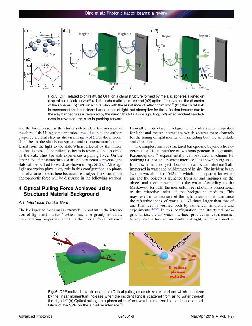
and the basic reason is the chirality-dependent transmission ofthe chiral slab. Using some optimized metallic units, the authorsproposed a chiral slab, as shown in Fig. 5(b1). For the incidentchiral beam, the slab is transparent and no momentum is trans-ferred from the light to the slab. When reflected by the mirror,the handedness of the reflection beam is reversed and absorbedby the slab. Thus the slab experiences a pulling force. On theother hand, if the handedness of the incident beam is reversed, theslab will be pushed forward, as shown in Fig. 5(b2).70 Althoughlight absorption plays a key role in this configuration, no photo-phoretic force appears here because it is analyzed in vacuum; thephotophoretic force will be discussed in the following sections.
4 Optical Pulling Force Achieved usingStructured Material Background
4.1 Interfacial Tractor Beam
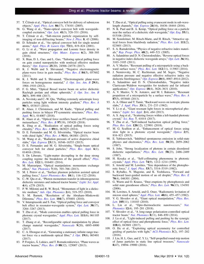
The background medium is extremely important in the interac-tion of light and matter,73 which may also greatly modulatethe scattering properties, and thus the optical force behavior.
Basically, a structured background provides richer propertiesfor light and matter interaction, which ensures more channelsfor the tuning of light momentum, including both the amplitudeand directions.
The simplest form of structured background beyond a homo-geneous one is an interface of two homogeneous backgrounds.Kajorndejnukul38 experimentally demonstrated a scheme forrealizing OPF on an air–water interface,74 as shown in Fig. 6(a).In this scheme, the object floats on the air–water interface (half-immersed in water and half-immersed in air). The incident beam(with a wavelength of 532 nm, which is transparent for water,air, and the object) is launched from air and impinges on theobject and then transmits into the water. According to theMinkowski formula, the momentum per photon is proportionalto the refractive index of the background medium. Thismay result in an increase of the light linear momentum sincethe refractive index of water is 1.33 times larger than that ofair. This idea is verified both by numerical simulation andexperiments.38,74,76 In this configuration, the structured back-ground, i.e., the air–water interface, provides an extra channelto amplify the forward momentum of light, which is absent in
Fig. 6 OPF realized on an interface. (a) Optical pulling on an air–water interface, which is realizedby the linear momentum increase when the incident light is scattered from air to water throughthe object.38 (b) Optical pulling on a plasmonic surface, which is realized by the directional exci-tation of the SPP on the air–silver interface.75
Fig. 5 OPF related to chirality. (a) OPF on a chiral structure formed by metallic spheres aligned ona spiral line (black curve):69 (a1) the schematic structure and (a2) optical force versus the diameterof the spheres. (b) OPF on a chiral slab with the assistance of reflection mirror:70 (b1) the chiral slabis transparent for the incident handedness of light, but absorptive for the reflection beams; due tothe way handedness is reversed by the mirror, the total force is pulling; (b2) when incident handed-ness is reversed, the slab is pushing forward.
Ding et al.: Photonic tractor beams: a review
Advanced Photonics 024001-6 Mar∕Apr 2019 • Vol. 1(2)

a homogeneous background. Apart from obtaining the OPF,this scheme is also valuable for distinguishing the validation ofdifferent forms of stress tensor and force density and helps toilluminate the Abraham–Minkowski debate (the detailed analy-sis of this debate is out of the scope of our topic; readersmay refer to papers by Pfeifer et al.,39 Milonni and Boyd,77
and Barnett78).Another interesting theoretical proposal on an interface is
using the plasmonic interface by Petrov et al.,75 as shown inFig. 6(b). In this scheme, two key factors result in the extremelyasymmetric excitation of the surface plasmon polariton (SPP) onthe plasmonic interface. The first one is the excitation of a rotat-ing dipole in the particle due to the interference of incident andreflected fields. The second one is the strongly asymmetricdirectional excitation of the SPP wave by the spin–orbital cou-pling of the rotating dipole and the SPP wave, which increasesthe linear momentum of the scattered wave along the interfacedirection. As a result, the object on the plasmonic interface isrecoiled in a backward direction.
4.2 Optical Pulling Force in Waveguide Channels
Another kind of structured background is the optical channels,which support various modes. Intaraprasonk and Fan79 reportedthe pulling force in a ring-waveguide system, as shown inFig. 7(a). In this scheme, the optical waveguide supports boththe zeroth-order and first-order modes, and the zeroth mode hasa larger effective forward momentum (i.e., the larger propaga-tion constant) than the first mode. When the waveguide is ex-cited using the first mode, and scattered resonantly by the ringresonator, part of the energy will transfer to the zeroth modeadiabatically without energy reflection, thus the momentum of
guiding mode is increased. As a result, the object (i.e., the ringresonator) experiences an OPF. In this scheme, the transversestability is also possible when the incident frequency is carefullytuned. Similarly, the pulling force can also be obtained viaa multimode fiber and particle system.82
Since the ring (as particles) is outside the multimode wave-guide (fiber) and couples with the guiding mode through theevanescent wave only, the scattering efficiency is low. Due tothis reason, another different configuration has been proposedby Zhu et al.,80 where a hollow core photonic crystal (PC) wave-guide is used, and the object is set inside the waveguide just atthe intensity peak locations. The PC waveguide also supportsboth the zeroth and first modes. When the first-order mode islaunched, part of it is scattered into the forward zeroth-ordermode (the reflections can be neglected by the optimization ofthe objects). Since the effective linear momentum of the guidingmode is increased, the object is recoiled naturally by the con-servation law of linear momentum. Actually, OPF is generic in alarge class of systems where more than one mode with differentmomentum densities exists, even in the scattering of heavy bary-ons into light leptons on cosmic strings.83
Except for the optical guiding mode, it is also possible toachieve the OPF using the mode near the cutting frequency.81,84,85
For an optical waveguide, it is known that the mode will be cutwhen the frequency is less than some critical value. For thosefrequencies below the cutting point, the launched source cannotpropagate but decays exponentially along the waveguide. Thisdecaying feature generates an intensity gradient force towardthe source direction. Thus an object will be pulled in such amode. On the other hand, when the frequency is tuned slightly,the mode can be switched between guiding and decaying,
Fig. 7 OPF realized in waveguide channels: (a) optical resonant pulling of a ring resonator bya dual-mode optical waveguide,79 (b) OPF in a hollow core photonic crystal waveguide,80 and(c) tunable optical pushing and pulling using a waveguide made of phase change material ofGe2Sb2Te5 (GST).81
Ding et al.: Photonic tractor beams: a review
Advanced Photonics 024001-7 Mar∕Apr 2019 • Vol. 1(2)

and the force can be switched accordingly between pushing andpulling.
More interestingly, Zhang et al.81 proposed a new method todynamically tune the direction of the optical force at the sameincident frequency, as shown in Fig. 7(c). The key point is thatthe waveguide is made of a phase change material ofGe2Sb2Te5(GST), which can change between the amorphous phase andcrystalline phase.81 When the waveguide is in the amorphousphase, a guiding mode with negligible decaying is obtained,which pushes the object along the waveguide. When the wave-guide is in the crystalline phase (illuminated by a pump light),the loss of GST increases greatly, the guiding mode becomesexponentially decaying, and the intensity gradient force willpull the object to the source direction. Using a similar decayingfeature, atoms around a hot object can be pulled due to theblackbody radiation.86
4.3 Optical Pulling Force in Waveguides with NegativeMode Index
Metamaterial with negative refractive index (NRI) is an interest-ing artificial optical material that has a refractive index of <0.87
The most interesting feature in this kind of material is the anti-parallel between the energy flow and the wavevector direction.Due to this property, it seems possible to generate OPF usingNRI material. However, an ideal NRI metamaterial exists onlyin theory (at least at the present time), and it is also inconvenientto pull an object in a solid NRI background made of subwave-length units. In this circumstance, researchers88–90 found that theeffective mode indices of some wave guiding modes are nega-tive and can be used to achieve OPF.
Salandrino and Christodoulides88 proposed a method to getan effective NRI background using a 2 × 3 dielectric waveguidearray, as shown in Fig. 8(a). The waveguide array is translationinvariant along the z axis (out-of-plane-direction); the wave-guide boundaries are shown by the six smaller squares. Thiswaveguide array is made of germanium square rods in air andis designed to mimic the Clarricoats-Waldron waveguide.91 Therefractive index of germanium is 4, and the side length andperiod are 600 and 850 nm, respectively. The effective modeindex of about −0.27 could be achieved at the wavelength of2 μm. In this case, the object (not shown) is placed insidethe empty region between the squares and can be pulled to thesource direction (out of the plane direction) continuously.
Fig. 8 OPF in waveguide channels with effective negative mode index: (a) a square dielectricwaveguide array, which mimics the Clarricoats-Waldron waveguide with negative mode index;88
(b1) and (b2) a plasmonic film in vacuum, which supports backward wave and can resonantly pulla dielectric sphere above it with very high-momentum-to-force efficiency;89 and (c) optical pulling ina biaxial slab layered structure.90
Ding et al.: Photonic tractor beams: a review
Advanced Photonics 024001-8 Mar∕Apr 2019 • Vol. 1(2)

In fact, the proposal reported in Ref. 88 is not easy to achievein practice, because infinitely periodic waveguide arrays or aperfect electrical conductor outer boundary is needed. Is it pos-sible to get an effective NRI mode in a more flexible structure?Using a plasmonic film embedded in air, the backward guidingmode with the phase velocity and energy velocity (the Poyntingvector) antiparallel can be obtained at proper frequencies,89,92,93 asshown in Fig. 8(b). For the scattering by a dielectric sphere ofthe backward wave, efficient momentum-to-force conversionappears, and pulling force reverse to the power flow isobtained.94 The peaks in Fig. 8(b) denote the resonant whisper-ing gallery mode of the spherical object. Also, an effective NRIcan be acquired by two biaxial dielectric slabs with a hollowlayer (for the setting of guiding particles) between them,90 asshown in Fig. 8(c). It is noted that the effective negative refrac-tive mode in a PC does not guarantee a pulling force, at least fora dipole object.95
4.4 Optical Pulling by the Self-Collimation Mode inPhotonic Crystals
Most recently, another quite interesting scheme for achievingOPF is theoretically proposed in a periodic PC.96 It is knownthat a PC can support different kinds of Bloch modes, whichprovide more possibilities for tailoring the interaction of light
and matter.97–99 The self-collimation (SC) mode is a uniqueBloch mode that can propagate infinitely long without diffrac-tion with a finite-transverse size, due to the coherent interactionof light with the periodic background.100 When an object isembedded in an SC mode, a continuous and robust OPF maybe exerted on it.
For an elongated object introduced into the SC beam, it scat-ters the SC mode adiabatically and forms a local intensity gra-dient on the object itself, as shown in Figs. 9(a) and 9(b). Thismeans that the light intensities in the fore part and rear part ofthe elongated object are sharply different, which generates anobvious negative intensity gradient force and contributes tothe pulling force greatly, as shown in Figs. 9(c) and 9(d). Onthe other hand, the scattering force component is extremelysmall in this case since the SC mode almost keeps its originalshape when scattered by the object. Actually, the SC mode canrecover itself within some distance after the scattering, whichensures the pulling ability of multiple objects.
Essentially, the intensity gradient pulling force here is thesame as those in traditional tweezers when the object is behindthe beam focus. However, the details and the final result arequite different. Here the intensity gradient field is generatedby the scattering of the object itself and shifts with the objectsynchronously, which is the reason for the continuous pullingforce over an infinitely long range. In optical tweezers, the
Fig. 9 OPF in a PC structure by the SC mode.96 (a) Scattering of the SC mode by an embeddedobject. (b) Intensity profile along the beam symmetry axis; a negative intensity gradient across theobject can be observed clearly, which is the physical origin for the OPF. (c) and (d) Intensity profileof the beam around the object at two different positions.
Ding et al.: Photonic tractor beams: a review
Advanced Photonics 024001-9 Mar∕Apr 2019 • Vol. 1(2)

intensity gradient is formed by an external focusing lens, whichis independent of the object. Thus an object will be trapped nearthe focus and can only be pulled when the external focusing lensis shifted mechanically. In other words, for the pulling in thismethod, the object acts as the focusing lens as well as the targetto be pulled. In this sense, the pulling force is self-induced, andthe object is “pulled” by itself.
5 Optical Pulling Force by PhotophoresisEffect
In addition to those direct OPF mentioned above, there are alsoreports of using the indirect optical force, i.e., the photophoresiseffect, which has been noticed by researchers for a longtime.101,102 Recently, this effect has captured the attention of
researchers again due to the rapid development of nanotechnol-ogy, which can finely control the absorption properties of micro-and nano-objects. In fluidic (both liquid and gaseous) environ-ments, when a laser beam illuminates an absorptive object,a temperature gradient appears on the object and bounces offthe molecules of the fluidic background asymmetrically. Asa result, the object may get a net force. Theoretically, the photo-phoretic force could be about 105 times larger than the directoptical force,103,104 which makes this force extremely importantin giant optical manipulation.105 Briefly, photophoretic force isinduced by inhomogeneous temperature distribution on an ob-ject when it absorbs incident light and bounces off the moleculesof a fluidic background asymmetrically. Recently, it has beensuccessfully used to enhance the trapping efficiency of a nano-object.106 Here, we discuss long-range pulling manipulation bythis force.
Fig. 10 Experimental demonstrations of OPF assisted by photophoretic force. (a) Stable pullingand pushing of a coated empty glass sphere using vector beams with a doughnut intensitypattern.107 For azimuthally polarized beam, the force is pulling, while for radially polarized beam,the force is pushing. (b) Pulling and pushing of a metallic plate on a fiber taper.108
Ding et al.: Photonic tractor beams: a review
Advanced Photonics 024001-10 Mar∕Apr 2019 • Vol. 1(2)

Shvedov et al.107 demonstrated stable long-range (at the scaletens of centimeters) polarization-controlled OTB. The objectused was a hollow glass sphere coated with a thin gold film(thickness of the coating layer was 7 to 15 nm, thickness ofthe glass sphere was about 300 nm, and the outer radius ofthe glass sphere was about 25 μm), which exemplifies a semi-transparent particle. The light beam used was a doughnut vectorbeam, which not only transported the object but also providedrestoring transverse force for stable trapping. The fluidic back-ground was air. Results showed that, for the radially polarizedincident beam, the sphere was pushed forward (at a speed about0.4 mm · s−1); for an azimuthally polarized beam, the spherewas pulled back stably (at a speed about 0.8 mm · s−1) at theincident power of 200 mW, as shown in Fig. 10(a). The physicalorigin of the force was the concomitant redistribution of theabsorbed light energy over the particle surface (defined asJ-factor), which depends not only on the thickness of each layer(the glass shell, the gold coating) but also on the polarization ofincident light. At the optimized particle parameters, the azimu-thally polarized beam generated a pulling force while the radi-ally polarized beam generated a pushing force.
Recently, Lu et al.108 reported the pushing and pulling ofa gold disk by the synergy of optical force and photophoreticforce, as shown in Fig. 10(b). Their experiment used a hexago-nal gold plate (side length 5.4 μm and thickness of 30 nm)sitting on a tapered fiber (with a cone angle of 6 deg), whichfocused the supercontinuum incident light gradually. When theAu-plate was located at the end of the taper, it was heated bythe light and was pulled backward by the photophoretic force.On the other hand, when the Au-plate was far from the taperedend, the radiation pressure pushed the object forward. Atthe incident power of 1.3 mW, the moving velocity was about30 to 40 μm∕s.
With the development of nanofabrication technology, re-searchers can now fabricate Janus microspheres or othershaped structures, which means that the absorptive feature isasymmetric.109–113 This kind of structure has been used to getcontrollable directional motion beyond the scope of opticalpulling operation. For example, using a trapped particle, thephotophoresis may also be used for a true three-dimensionaldisplay by scanning.114
6 Conclusions and OutlookFrom science fiction to the first theoretical proposal and the firstexperimental demonstration, OPF has witnessed rapid develop-ment within recent years. On the one hand, OPF has stimulated avast number of theoretical investigations of light–matter inter-action. On the other hand, this force provides a new freedom foroptical manipulation technology. Now we are able to opticallymanipulate all the freedoms of motion of a micro–object, whichinclude trapping (fixed at some point), translating (pushing,pulling, and lateral shifting), and rotating (orbital and spin).
We roughly classify the mechanisms of optical pulling intofour different kinds, and each mechanism has its own strengthand weakness. Generally speaking, most of the objects to bepulled are comparable to or smaller (dipole approximation) thanthe wavelengths, whereas those operated in a geometrical opticsregion and photophoretic force dominated operations can pulllarger objects of tens of micrometers. The pulling of abovemillimeter scale is still challenging. For the first one by engi-neering the incident beam, the Bessel beam and solenoid beamwith spiral intensity profiles are the most promising beams.
In practice, however, generating such beams is not easy. In com-parison, the method using the interference of multiple beamsseems more flexible, such as the interference of plane waves,Bessel beams, and Gaussian beams. For the second methodof tailoring the object’s electromagnetic parameters, one usuallyshould resort to objects with exotic optical parameters, such asoptical gain, chirality, and anisotropy. Also, the assistance of astructured light beam is always required in this mechanism. Forthe third method of using a structured background, the waveguiding channels supporting multiple modes and backwardmodes with an effective NRI are the most promising candidates.At the same time, a single interface of different medium, such asair–water and air–metal interfaces, is a simple enough model,which can increase the forward light momentum along theinterface direction, and in turn get an OPF. Also the periodicPC backgrounds support various Bloch modes, such as theSC mode, and provide more channels for tailoring the momen-tum exchange between light and object, which is also a goodcandidate for OPF. Finally, OPF using the cooperation of opticalforce and photophoretic force can achieve larger force andlonger operation distance, which shows potential applicationsin optical manipulation.
As a rapid progressing domain, the OPF is expected to attractmore and more attention in the following years. More intriguingoptical pulling mechanisms and experiments will be proposedand demonstrated. Structured nanophotonic structures, includingthe PCs,96 plasmonics, and metamaterials/metasurfaces,115,116
can support novel modes (Bloch modes, surface mode, andsubwavelength confinement); therefore, these systems deservefurther exploring. Recently, photonic topological structures, inwhich the propagating and scattering behavior of light is uniqueand interesting optical force may be possible, have been inves-tigated intensively.117 When integrated with microfluidic envi-ronment, the photophoresis effect may come into being due tolight absorption, and the manipulation capacity will be greatlyenhanced. When vector and vortex beams are combined withspecial objects, such as chirality, phase change material, andnanoresonant materials, OPF can be achieved in a flexible andhighly efficient way. Without a doubt, developments in thisrealm will continuously reveal more and more novel phenomenain light–matter interaction and bring new technologies forbiology, medical science, chemistry, and nanotechnology.
Acknowledgments
This work was supported by the National Natural ScienceFoundation of China (Grant Nos. 11874134 and 11474077).
References
1. A. Ashkin, “Acceleration and trapping of particles by radiationpressure,” Phys. Rev. Lett. 24(4), 156–159 (1970).
2. A. Ashkin et al., “Observation of a single-beam gradient forceoptical trap for dielectric particles,” Opt. Lett. 11(5), 288–290(1986).
3. A. Ashkin and J. M. Dziedzic, “Optical trapping and manipula-tion of viruses and bacteria,” Science 235(4795), 1517–1520(1987).
4. F. M. Fazal and S. M. Block, “Optical tweezers study life undertension,” Nat. Photonics 5, 318–321 (2011).
5. M. Koch and A. Rohrbach, “Object-adapted optical trappingand shape-tracking of energy-switching helical bacteria,” Nat.Photonics 7, 680–690 (2013).
Ding et al.: Photonic tractor beams: a review
Advanced Photonics 024001-11 Mar∕Apr 2019 • Vol. 1(2)

6. Y. Pang et al., “Optical trapping of individual human immuno-deficiency viruses in culture fluid reveals heterogeneity withsingle-molecule resolution,” Nat. Nanotechnol. 9(8), 624–630(2014).
7. K. Svoboda et al., “Direct observation of kinesin steppingby optical trapping interferometry,” Nature 365, 721–727(1993).
8. L. R. Liu et al., “Building one molecule from a reservoir oftwo atoms,” Science 360(6391), 900–903 (2018).
9. J. Chan et al., “Laser cooling of a nanomechanical oscillatorinto its quantum ground state,” Nature 478, 89–92 (2011).
10. C. H. Metzger, “Cavity cooling of a microlever,” Nature 432,1002–1005 (2004).
11. A. Schliesser et al., “Resolved-sideband cooling and positionmeasurement of a micromechanical oscillator close to theHeisenberg uncertainty limit,” Nat. Phys. 5, 509–514 (2009).
12. N. Descharmes et al., “Observation of backaction and self-induced trapping in a planar hollow photonic crystal cavity,”Phys. Rev. Lett. 110(12), 123601 (2013).
13. M. Righini et al., “Surface plasmon optical tweezers: tunable op-tical manipulation in the femtonewton range,” Phys. Rev. Lett.100(18), 186804 (2008).
14. M. L. Juan et al., “Self-induced back-action optical trapping ofdielectric nanoparticles,” Nat. Phys. 5(12), 915–919 (2009).
15. S. Sukhov and A. Dogariu, “Non-conservative optical forces,”Rep. Progr. Phys. 80(11), 112001 (2017).
16. C. Zensen et al., “Pushing nanoparticles with light—a femtonew-ton resolved measurement of optical scattering forces,” APLPhotonics 1(2), 026102 (2016).
17. A. Dogariu, S. Sukhov, and J. J. Sáenz, “Optically induced‘negative forces’,” Nat. Photonics 7, 24–27 (2013).
18. M. Nieto-Vesperinas, “Optical torque: electromagnetic spin andorbital-angular-momentum conservation laws and their signifi-cance,” Phys. Rev. A 92(4), 043843 (2015).
19. J. Ahn et al., “Optically levitated nanodumbbell torsion balanceand GHz nanomechanical rotor,” Phys. Rev. Lett. 121(3), 033603(2018).
20. F. Borghese et al., “Radiation torque and force on opticallytrapped linear nanostructures,” Phys. Rev. Lett. 100(16), 163903(2008).
21. R. Reimann et al., “GHz rotation of an optically trapped nano-particle in vacuum,” Phys. Rev. Lett. 121(3), 033602 (2018).
22. M. P. J. Lavery et al., “Detection of a spinning object usinglight’s orbital angular momentum,” Science 341(6145), 537–540 (2013).
23. H. Lina and O. J. F. Martin, “Reversal of the optical force ina plasmonic trap,” Opt. Lett. 33(24), 3001–3003 (2008).
24. S.-H. Lee, Y. Roichman, and D. G. Grier, “Optical solenoidbeams,” Opt. Express 18(7), 6988–6993 (2010).
25. A. Mizrahi and Y. Fainman, “Negative radiation pressure on gainmedium structures,” Opt. Lett. 35(20), 3405–3407 (2010).
26. S. Sukhov and A. Dogariu, “On the concept of ‘tractor beams’,”Opt. Lett. 35(22), 3847–3849 (2010).
27. J. Chen et al., “Optical pulling force,” Nat. Photonics 5, 531–534(2011).
28. A. Novitsky, C.-W. Qiu, and H. Wang, “Single gradient less lightbeam drags particles as tractor beams,” Phys. Rev. Lett. 107(20),203601 (2011).
29. P. L. Marston, “Axial radiation force of a Bessel beam on a sphereand direction reversal of the force,” J. Acoust. Soc. Am. 120(6),3518–3524 (2006).
30. P. L. Marston, “Negative axial radiation forces on solid spheresand shells in a Bessel beam,” J. Acoust. Soc. Am. 122(6), 3162–3165 (2007).
31. H. Punzmann et al., “Generation and reversal of surface flows bypropagating waves,” Nat. Phys. 10(9), 658–663 (2014).
32. A. A. Gorlach et al., “Matter-wave tractor beams,” Phys. Rev.Lett. 118(18), 180401 (2017).
33. Y. Harada and T. Asakura, “Radiation forces on a dielectricsphere in the Rayleigh scattering regime,” Opt. Commun.124(5–6), 529–541 (1996).
34. M. Nieto-Vesperinas, R. Gomez-Medina, and J. J. Saenz,“Angle-suppressed scattering and optical forces on submicrom-eter dielectric particles,” J. Opt. Soc. Am. A 28(1), 54–60(2011).
35. J. M. Geffrin et al., “Magnetic and electric coherence in forward-and back-scattered electromagnetic waves by a single dielectricsubwavelength sphere,” Nat. Commun. 3, 1171 (2012).
36. R. Gómez-Medina et al., “Electric and magnetic optical responseof dielectric nanospheres: optical forces and scattering anisotropy,”Photonics Nanostruct. Fundam. Appl. 10(4), 345–352 (2012).
37. A. Ashkin, “Forces of a single-beam gradient laser trap on a di-electric sphere in the ray optics regime,” J. Biophys. 61, 569–582(1992).
38. V. Kajorndejnukul et al., “Linear momentum increase andnegative optical forces at dielectric interface,” Nat. Photonics7(10), 787–790 (2013).
39. R. N. C. Pfeifer et al., “Momentum of an electromagnetic wave indielectric media,” Rev. Mod. Phys. 79(4), 1197–1216 (2007).
40. J. J. Sáenz, “Optical forces: laser tractor beams,” Nat. Photonics5(9), 514–515 (2011).
41. Y. Roichman et al., “Optical forces arising from phase gradients,”Phys. Rev. Lett. 100(1), 013602 (2008).
42. L. Carretero et al., “Helical tractor beam: analytical solution ofRayleigh particle dynamics,” Opt. Express 23(16), 20529–20539(2015).
43. A. Novitsky, C.-W. Qiu, and A. Lavrinenko, “Material-indepen-dent and size-independent tractor beams for dipole objects,”Phys. Rev. Lett. 109(2), 023902 (2012).
44. Z. Xie, V. Armbruster, and T. Grosjean, “Axicon on a gradientindex lens (AXIGRIN): integrated optical bench for Bessel beamgeneration from a point-like source,” Appl. Opt. 53(26), 6103–6107 (2014).
45. I. Moreno et al., “Nondiffracting Bessel beams with polarizationstate that varies with propagation distance,” Opt. Lett. 40(23),5451–5454 (2015).
46. W. T. Chen et al., “Generation of wavelength-independent sub-wavelength Bessel beams using metasurfaces,” Light: Sci. Appl.6(5), e16259 (2017).
47. C. Pfeiffer and A. Grbic, “Generating stable tractor beams withdielectric metasurfaces,” Phys. Rev. B 91(11), 115408 (2015).
48. B. Liao et al., “Cloaking core-shell nanoparticles from con-ducting electrons in solids,” Phys. Rev. Lett. 109(12), 126806(2012).
49. S. Xu et al., “Experimental demonstration of a free-space cylin-drical cloak WITHOUT superluminal propagation,” Phys. Rev.Lett. 109(22), 223903 (2012).
50. N. Wang et al., “Optimized optical “tractor beam” for core-shellnanoparticles,” Opt. Lett. 39(8), 2399–2402 (2014).
51. A. Novitsky et al., “Pulling cylindrical particles using a soft-nonparaxial tractor beam,” Sci. Rep. 7, 652 (2017).
52. N. Wang et al., “Dynamical and phase-diagram study on stableoptical pulling force in Bessel beams,” Phys. Rev. A 87(6),063812 (2013).
53. J. Damková et al., “Enhancement of the ‘tractor-beam’ pullingforce on an optically bound structure,” Light: Sci. Appl. 7(1),17135 (2018).
54. O. Brzobohatý et al., “Experimental demonstration of opticaltransport, sorting and self-arrangement using a ‘tractor beam’,”Nat. Photonics 7(2), 123–127 (2013).
55. S. Sukhov and A. Dogariu, “Negative nonconservative forces:optical ‘tractor beams’ for arbitrary objects,” Phys. Rev. Lett.107(20), 203602 (2011).
56. D. B. Ruffner and D. G. Grier, “Optical conveyors: a classof active tractor beams,” Phys. Rev. Lett. 109(16), 163903(2012).
Ding et al.: Photonic tractor beams: a review
Advanced Photonics 024001-12 Mar∕Apr 2019 • Vol. 1(2)
57. T. Cižmár et al., “Optical conveyor belt for delivery of submicronobjects,” Appl. Phys. Lett. 86(17), 174101 (2005).
58. G. Wang et al., “Nano-optical conveyor belt with waveguide-coupled excitation,” Opt. Lett. 41(3), 528–531 (2016).
59. T. Cižmár et al., “Sub-micron particle organization by self-imaging of non-diffracting beams,” New J. Phys. 8, 43 (2006).
60. D. Schrader et al., “An optical conveyor belt for single neutralatoms,” Appl. Phys. B: Lasers Opt. 73(8), 819–824 (2001).
61. G. Li et al., “Wave propagation and Lorentz force density ingain chiral structures,” Opt. Mater. Express 6(2), 388–395(2016).
62. X. Bian, D. L. Gao, and L. Gao, “Tailoring optical pulling forceon gain coated nanoparticles with nonlocal effective mediumtheory,” Opt. Express 25(20), 24566–24578 (2017).
63. K. J. Webb and S. Shivanand, “Negative electromagneticplane-wave force in gain media,” Phys. Rev. E 84(5), 057602(2011).
64. K. J. Webb and S. Shivanand, “Electromagnetic plane-waveforces on homogeneous material,” J. Opt. Soc. Am. B 29(8),1904–1910 (2012).
65. F. G. Mitri, “Optical Bessel tractor beam on active dielectricRayleigh prolate and oblate spheroids,” J. Opt. Soc. Am. B34(5), 899–908 (2017).
66. A. Novitsky and C.-W. Qiu, “Pulling extremely anisotropic lossyparticles using light without intensity gradient,” Phys. Rev. A90(5), 053815 (2014).
67. R. Alaee, J. Christensen, and M. Kadic, “Optical pulling andpushing forces in bilayer PT-symmetric structures,” Phys. Rev.Appl. 9(1), 014007 (2018).
68. R. Alaee et al., “Optical force rectifiers based on PT-symmetricmetasurfaces,” Phys. Rev. B 97(19), 195420 (2018).
69. K. Ding et al., “Realization of optical pulling forces usingchirality,” Phys. Rev. A 89(6), 063825 (2014).
70. D. E. Fernandes and M. G. Silveirinha, “Optical tractor beamwith chiral light,” Phys. Rev. A 91(6), 061801 (2015).
71. M. Wang et al., “Radiation pressure of active dispersive chiralslabs,” Opt. Express 23(13), 16546–16553 (2015).
72. D. E. Fernandes and M. G. Silveirinha, “Single-beam opticalconveyor belt for chiral particles,” Phys. Rev. Appl. 6(1),014016 (2016).
73. S. De Liberato, “Light-matter decoupling in the deep strongcoupling regime: the breakdown of the purcell effect,” Phys.Rev. Lett. 112(1), 016401 (2014).
74. M. Mansuripur, “Optical manipulation: momentum exchangeeffect,” Nat. Photonics 7(10), 765–766 (2013).
75. M. I. Petrov et al., “Surface plasmon polariton assisted opticalpulling force,” Laser Photonics Rev. 10(1), 116–122 (2016).
76. C.-W. Qiu et al., “Photon momentum transfer in inhomogeneousdielectric mixtures and induced tractor beams,” Light: Sci. Appl.4(4), e278 (2015).
77. P. W. Milonni and R. W. Boyd, “Momentum of light in a dielec-tric medium,” Adv. Opt. Photonics 2(4), 519–553 (2010).
78. S. M. Barnett, “Resolution of the Abraham–MinkowskiDilemma,” Phys. Rev. Lett. 104(7), 070401 (2010).
79. V. Intaraprasonk and S. Fan, “Optical pulling force and conveyorbelt effect in resonator-waveguide system,” Opt. Lett. 38(17),3264–3267 (2013).
80. T. Zhu et al., “Mode conversion enables optical pulling force inphotonic crystal waveguides,” Appl. Phys. Lett. 111(6), 061105(2017).
81. T. Zhang et al., “Reconfigurable optical manipulation by phasechange material waveguides,” Nanoscale 9(20), 6895–6900(2017).
82. C. A. Ebongue et al., “Generating a stationary infinite range trac-tor force via a multimode optical fibre,” J. Opt. 19(6), 065401(2017).
83. P. Forgács, Á. Lukács, and T. Romanczukiewicz, “Plane waves astractor beams,” Phys. Rev. D 88(12), 125007 (2013).
84. T. Zhu et al., “Optical pulling using evanescent mode in sub-wave-length channels,” Opt. Express 24(16), 18436–18444 (2016).
85. N. K. Paul and B. A. Kemp, “Optical pulling force on a particlenear the surface of a dielectric slab waveguide,” Opt. Eng. 55(1),015106 (2016).
86. M. Sonnleitner, M. Ritsch-Marte, and H. Ritsch, “Attractive op-tical forces from blackbody radiation,” Phys. Rev. Lett. 111(2),023601 (2013).
87. S. A. Ramakrishna, “Physics of negative refractive index materi-als,” Rep. Progr. Phys. 68(2), 449–521 (2005).
88. A. Salandrino and D. N. Christodoulides, “Reverse optical forcesin negative index dielectric waveguide arrays,” Opt. Lett. 36(16),3103–3105 (2011).
89. A. V. Maslov, “Resonant pulling of a microparticle using a back-ward surface wave,” Phys. Rev. Lett. 112(11), 113903 (2014).
90. J. Nemirovsky, M. C. Rechtsman, and M. Segev, “Negativeradiation pressure and negative effective refractive index viadielectric birefringence,” Opt. Express 20(8), 8907–8914 (2012).
91. A. Salandrino and D. N. Christodoulides, “Negative indexClarricoats-Waldron waveguides for terahertz and far infraredapplications,” Opt. Express 18(4), 3626–3631 (2010).
92. A. V. Maslov, V. N. Astratov, and M. I. Bakunov, “Resonantpropulsion of a microparticle by a surface wave,” Phys. Rev. A87(5), 053848 (2013).
93. A. A. Oliner and T. Tamir, “Backward waves on isotropic plasmaslabs,” J. Appl. Phys. 33(1), 231–233 (1962).
94. Y. Li et al., “Giant resonant light forces in microspherical pho-tonics,” Light: Sci. Appl. 2(4), e64 (2013).
95. A. S. Ang et al., “Scattering forces within a left-handed photoniccrystal,” Sci. Rep. 7, 41014 (2017).
96. T. Zhu et al., “Self-induced backaction optical pulling force,”Phys. Rev. Lett. 120(12), 123901 (2018).
97. M. G. Scullion et al., “Enhancement of optical forces usingslow light in a photonic crystal waveguide,” Optica 2(9),816–821 (2015).
98. E. Yablonovitch, “Inhibited spontaneous emission in solid-statephysics and electronics,” Phys. Rev. Lett. 58(20), 2059–2062(1987).
99. S. John, “Strong localization of photons in certain disordereddielectric superlattices,” Phys. Rev. Lett. 58(23), 2486–2489(1987).
100. H. Kosaka et al., “Self-collimating phenomena in photoniccrystals,” Appl. Phys. Lett. 74(9), 1212–1214 (1999).
101. S. Arnold and M. Lewittes, “Size dependence of the photopho-retic force,” J. Appl. Phys. 53(7), 5314–5319 (1982).
102. S. Rybalko, N. Magome, and K. Yoshikawa, “Forward andbackward laser-guided motion of an oil droplet,” Phys. Rev. E70(4), 046301 (2004).
103. G. Wurm and O. Krauss, “Dust eruptions by photophoresis andsolid state greenhouse effects,” Phys. Rev. Lett. 96(13), 134301(2006).
104. M. Lewittes, S. Arnold, and G. Oster, “Radiometric levitation ofmicron sized spheres,” Appl. Phys. Lett. 40(6), 455–457 (1982).
105. V. G. Shvedov et al., “Giant optical manipulation,” Phys. Rev.Lett. 105(11), 118103 (2010).
106. L. Lin et al., “Opto-thermoelectric nanotweezers,” Nat.Photonics 12(4), 195–201 (2018).
107. V. Shvedov et al., “A long-range polarization-controlled opticaltractor beam,” Nat. Photonics 8(11), 846–850 (2014).
108. J. Lu et al., “Light-induced pulling and pushing by the synergiceffect of optical force and photophoretic force,” Phys. Rev. Lett.118(4), 043601 (2017).
109. O. Ilic et al., “Exploiting optical asymmetry for controlledguiding of particles with light,” ACS Photonics 3(2), 197–202(2016).
110. J. Liu, H. L. Guo, and Z. Y. Li, “Self-propelled round-trip motionof Janus particles in static line optical tweezers,” Nanoscale8(47), 19894–19900 (2016).
Ding et al.: Photonic tractor beams: a review
Advanced Photonics 024001-13 Mar∕Apr 2019 • Vol. 1(2)

111. H. Eskandarloo, A. Kierulf, and A. Abbaspourrad, “Light-harvesting synthetic nano- and micromotors: a review,”Nanoscale 9(34), 12218–12230 (2017).
112. V. Sridhar, B.-W. Park, and M. Sitti, “Light-driven Janus hollowmesoporous TiO2-Au microswimmers,” Adv. Funct. Mater. 28,1704902 (2018).
113. H. Zeng et al., “Light-fueled microscopic walkers,” Adv. Mater.27(26), 3883–3887 (2015).
114. D. E. Smalley et al., “A photophoretic-trap volumetric display,”Nature 553, 486–490 (2018).
115. F. Ding, A. Pors, and S. I. Bozhevolnyi, “Gradient metasurfaces:a review of fundamentals and applications,” Rep. Progr. Phys.81(2), 026401 (2018).
116. M. L. Tseng et al., “Metalenses: advances and applications,”Adv. Opt. Mater. 6, 1800554 (2018).
117. L. Lu, J. D. Joannopoulos, and M. Soljačić, “Topological pho-tonics,” Nat. Photonics 8, 821–829 (2014).
Weiqiang Ding is a full professor at the Physics Department of HarbinInstitute of Technology. His research focuses on optical manipulationand nanophotonics, including novel optical manipulation using the
Bloch modes in periodic photonic lattices, optical pulling force, and em-bedded metasurface in nanophotonic structures.
Tongtong Zhu is a PhD candidate at Harbin Institute of Technology,China. He works on optical manipulation and tries to combine optical forcewith other physical mechanics. His research interests include structuredlight, topological photonics, and light momentum in complex media.
Lei-Ming Zhou joined National University of Singapore as a researchfellow in 2018. His research interests include optical manipulation withvortex beam, novel optical force, and angular momentum conversion oflight beams.
Cheng-Wei Qiu received his BEng and PhD degrees in 2003 and 2007,respectively. After a postdoc at MIT, he joined NUS as an assistant pro-fessor in Dec 2009 and was promoted to associate professor with tenurein Jan 2017. In January of 2018, he was promoted to dean’s chair inthe Faculty of Engineering, NUS. His research is known for structuredlight for beam and nanoparticle manipulation and metasurfaces.
Ding et al.: Photonic tractor beams: a review
Advanced Photonics 024001-14 Mar∕Apr 2019 • Vol. 1(2)


![Novel Design for Photonic Crystal Ring Resonators Based ...jopn.miau.ac.ir/article_3046_01eb01affabdaa909e9328069782f311.pdf · employing photonic crystals [4]. In recent years, photonic](https://img.pdfslide.us/doc/110x75/5e7ed386707cf3599e6c8522/novel-design-for-photonic-crystal-ring-resonators-based-jopnmiauacirarticle304601eb01affabd.jpg)