Embed Size (px)
Citation preview

Photonic encoder and decoder for opticalcode-division multiplexing with time-to-spaceconverters and angle-multiplexed holograms
Hiroyuki Tsuda and Hirokazu Takenouchi
A photonic encoder–decoder pair for optical code-division multiplexing �OCDM� that uses time-to-spaceconverters and angle-multiplexed holograms is proposed. The encoder converts the pulse from eachinput port into a specific code and multiplexes input signals into the output port. The hologram in thedecoder generates a correlation waveform between the transmitted code and the recorded code. Theperformance of the OCDM system with the encoder–decoder pair is estimated. The maximum spectralefficiency for 8-bit length orthogonal codes in the worst case at a bit-error rate of 10�9 is 0.17 �bits�s��Hzwhen the number of channels is 8. © 2002 Optical Society of America
OCIS codes: 060.0060, 060.4230, 070.6020, 090.4220, 200.4560.
1. Introduction
A large-capacity photonic backbone network of morethan several terabits per second will be required formeeting increasing demands for capacity in commu-nication. Recent reports have shown that such anetwork can be achieved by use of the entire band-width of an optical fiber. One could accomplish thisby �1� extending the bandwidths of optical amplifiersand increasing the number of wavelength-divisionmultiplexing �WDM� channels, �2� improving spectralefficiency with high-speed �40 Gbits�s or more� andefficient modulation schemes �non-return-to-zero,duobinary, carrier suppression return-to-zero, etc.�,and �3� introducing photonic routing functions intooptical nodes to reduce optical-to-electrical andelectrical-to-optical converters and to increase theutilization of the channel bandwidth. The first andthe second procedures are finding steadily improvingimplementation, but ways with which to accomplishthe third are not clear. Wavelength converters arekey devices for WDM-based photonic routing; how-ever, a practical wavelength converter has not yet
H. Tsuda �[email protected]� is with Keio University, 3-14-1Hiyoshi, Kohoku-ku, Yokohama, Kanagawa 223-8522, Japan. H.Takenouchi is with NTT Photonics Laboratories, 3-1 Morinosato-Wakamiya, Atsugi, Kanagawa 243-0198, Japan.
Received 1 September 2000; revised manuscript received 21 Sep-tember 2001.
0003-6935�02�020290-08$15.00�0© 2002 Optical Society of America
290 APPLIED OPTICS � Vol. 41, No. 2 � 10 January 2002
been developed, and most proposed wavelength con-verters could not independently handle eachwavelength-multiplexed signal. The use of opticalcode-division multiplexing �OCDM� is attractive be-cause it is relatively easy to convert codes with pas-sive optical code converters. Furthermore, opticalcodes are rich in variety and are not directly relatedto physical parameters. OCDM would be used incombination with time-division multiplexing, spatial-division multiplexing, and WDM to enhance the flex-ibility of the photonic network in both backbone andsubscriber networks. To provide a practical OCDMsystem, however, requires the development of an ef-ficient photonic encoder–decoder with high spectralefficiency. We have calculated the spectral effi-ciency of the proposed device and confirmed its per-formance.
There are two principal kinds of optical encodingmethod, coding in the frequency domain �spectral en-coding� and coding in the time domain. Frequency-domain OCDM was proposed and successfullydemonstrated by Weiner and co-workers.1–3 Binaryphase encoding of the spectrum of an optical pulsewith a maximum length sequence �M sequence� wasused. Frequency-domain OCDM has the advan-tages that control of the amplitude and the phase ofeach pulse is not necessary and that all the signals ofthe channels are encoded or decoded simultaneously.However, an ultrafast all-optical threshold device hasto be used for the discrimination of pulses. A time-domain OCDM and pattern matching of the opticalheaders of the optical cells of an asynchronous trans-

fer mode system have been studied for more than 10years by many researchers.4–7 The time-domainOCDM does not require a high-speed threshold de-vice, but every channel requires one transversal filterpair so a multiplexer would become bulky even ifplanar lightwave circuits �PLCs� were used. Fur-thermore, stable and accurate control of the phases ofoptical pulses is difficult to achieve with transversalfilters.
We propose a novel configuration of an optical en-coder and decoder in which time-to-space convertersand an angle-multiplexed hologram are used. Theproposed encoder manipulates the spectrum of theinput pulse by using the angle-multiplexed hologramin the spectral plane to generate multiplexed time-domain orthogonal signals, and the decoder gener-ates correlation waveforms between the input signalsand the recorded signals. The proposed device hasthe advantages of both frequency-domain OCDM andtime-domain OCDM. The use of spectral hologra-phy for coding and decoding of temporal waveformwas proposed by Mazurenko.8,9 We modified hisconcept to configure a photonic encoder–decoder pairthat has multiplexing and demultiplexing functionsby using optical orthogonal codes. Furthermore, theconcept can be integrated in a PLC with arrayedwaveguides. Previously Kurokawa et al. developeda time-to-space conversion–based photonic signalprocessor, using PLC technology.10 A spectralencoder–decoder pair for frequency–domain OCDMwas fabricated, and error-free, 40-km transmission ofencoded signals was successfully demonstrated.11–13
These previous papers showed that part of the newlyproposed photonic encoder–decoder could be fabri-cated by use of the same technology. The proposedphotonic encoder–decoder with angle-multiplexedholograms has several advantages compared with aconventional encoder–decoder: �1� Optical orthogo-nal codes can be generated stably without fine controlof the phase of each waveguide, �2� all the channelsignals are processed simultaneously to facilitatesynchronization of the channels, and �3� an all-opticalthreshold device is not necessary.
In this paper we briefly explain the concept of ourencoder–decoder �Section 2�. In Section 3 we studyanalytically the functions of the proposed encoder–decoder with a two-dimensional configuration. InSection 4 we estimate the performance of the OCDMsystem with the proposed device and discuss theproblems to be solved to design a practical device.
2. Configuration of Photonic Encoder and Decoder byUse of Angle-Multiplexed Holograms
Figure 1 shows schematically the dispersive elementintegrated on the substrate by use of PLC technology.The dispersive element converts the temporal wave-form into a spatiotemporal waveform. The arrayedwaveguide is commonly used for wavelength-divisionmultiplexers and demultiplexers. Input temporalwaveform fin�t� is distributed to each waveguide thatis part of the arrayed waveguide with an envelopeamplitude distribution of w
t. The number ofwaveguides is usually 100–1000, and the time delaybetween adjacent waveguides is 0.1–1.0 ps. wt de-notes the time window of the dispersive element, andthe delay between the longest waveguide and theshortest waveguide determines the maximum timeduration of the signal. The inverse of the time delaybetween adjacent waveguides defines the width of thespectral window and determines the shortest pulsewidth of the signal. A spatiotemporal waveform,fout�x, t�, is generated on the output of the arrayedwaveguide. It is given by
fout� x, t� � wt� x� fin� x � t���, (1)
� �m
p�0, (2)
where � is the figure of the merit of the dispersiveelement, p is the pitch of the arrayed waveguide onthe output, �0 is the center frequency of the pulse, andm is the diffraction order. The output waveformmoves at a velocity of 1�� in the x direction.
The configuration of the photonic encoder is shownin Fig. 2�a�. The dispersive elements are used forgenerating spatiotemporal waveforms. Each encod-ing signal–reference signal pair has a different angleof intersection. The reference signals and the encod-ing signals should move at the same velocity for re-cording the interference patterns among them. Thesame interference patterns can be obtained by use ofstationary spatial patterns with the same envelope,or a computer-generated hologram can be used. Theencoded signal is generated by illumination of thehologram with the corresponding spatiotemporal ref-erence signal. The encoded signal is multiplexed byuse of several reference signals at the same time.The dispersive element at the output of the system
Fig. 1. Dispersive element integrated upon a substrate by PLCtechnology. The input temporal waveform fin�t� is distributed toeach waveguide of the arrayed waveguide with an envelope am-plitude distribution of wt. The number of waveguides is usually100–1000, and the time delay between adjacent waveguides is0.1–1.0 ps. The spatiotemporal waveform, fout�x, t�, is generatedon the output of the arrayed waveguide. The output waveformmoves at a velocity of 1�� in the x direction.
10 January 2002 � Vol. 41, No. 2 � APPLIED OPTICS 291

2
converts the spatiotemporal waveform again into atemporal waveform.
Figure 2�b� illustrates the configuration of the pho-tonic decoder �demultiplexer�. Analogously to opti-cal signal processing with a conventional hologram,the light diffracted by illumination of a spatiotempo-ral signal includes correlation and convolution wave-forms between the input signal and the recordedsignals. If we use an optical orthogonal signal, theautocorrelation waveform will be diffracted in direc-tions determined by the recording orientation. Thediscrimination between 1 and 0 will be made aftergating of the center part of the correlation wave-forms.
92 APPLIED OPTICS � Vol. 41, No. 2 � 10 January 2002
3. Analysis of Encoding and Decoding of theOptical Pulses
From a practical viewpoint, three-dimensional ar-rangements, as shown in Fig. 2, are too bulky. Fig-ures 3�a� and 3�b� show schematic configurationsof a photonic encoder and a photonic decoder, re-spectively, in a two-dimensional arrangement.Several dispersive elements are integrated uponthe same substrate. If an efficient mirror or a lenscan be fabricated in a PLC, the entire system will beintegrated. The hologram can be attached by ahybrid integration technique that is already usedfor inserting photonic elements �laser diode, retar-
Fig. 2. �a� Configuration of the photonic encoder �multiplexer� of the three-dimensional arrangement. The dispersive elements are usedfor converting a temporal waveform into a spatiotemporal waveform and vice versa. Each encoding signal and reference signal pair hasa different angle of intersection. A computer-generated hologram instead of a recording optical system may be used. The encoded signalis generated by illumination of the hologram with the corresponding spatiotemporal reference signal. �b� Configuration of the photonicdecoder �demultiplexer�. The light diffracted by illumination of the spatiotemporal signal includes correlation and convolution waveformsbetween the input signal and the recorded signals. If we use an optical orthogonal signal, the autocorrelation waveform will be diffractedto directions determined by the recording orientation.

dation plate, polarizer, etc.� into a PLC. In thisanalysis, an ideal angle-multiplexed hologram wasassumed.
The orthogonal signal, hk�x�, is recorded in the ho-logram by the angle-multiplexed technique. It isbased on an n-bit-length orthogonal code, hk�. hk�x�is given by
hk� x� � �l�1
N
hk,l�p� x � lTA�, (3)
where hk,l� is the lth element of hk� �1 or �1�, p�x� isa peaked function, and TA is the spacing of the peaks.The input reference pulse waveform is assumed to beg0�t�exp�2i�0t�, and it is converted into a spatiotem-poral waveform by the input dispersive elements.The spatiotemporal reference waveform, gk�x, t�, isgiven by
gk� x, t� � wt x � �k � 1��� g0 x � �k � 1�� � t���
� exp�2i�0 t�, (4)
� � L , (5)
Fig. 3. �a� Schematic of the proposed photonic encoder for the two-upon the same substrate. gk�x, t� is a spatiotemporal reference waLf is the focal length of the lenses. �b� Schematic configuration oek�x�, t� is the diffracted spatiotemporal correlation waveform. Thby optical gating and is discriminated for determination of the sig
f
where � is the pitch of the dispersive element and Lfis the focal length of the lens. The total width of thetime window should be narrower than � but widerthan the code sequence. For a simple analysis it isassumed that the hologram is thin and the transmit-tance is modulated. The amplitude transmittanceof the angle-multiplexed hologram is given by
T��x� � A0 � A1 �k�1
N
Hk��x� Hk*��x� � G0��x�G0*��x��
� A1 �k�1
N
Hk��x�G0*��x�exp�2ik��x�
� G0��x� Hk*��x�exp��2ik��x��, (6)
where A0 and A1 are constants and Hk��x� and G0��x�are Fourier transforms of hk�x� and g0�x�, respec-tively. The first-order diffracted light, illuminatedby ¥k�1
N gk�x, t�, is given by
� �k�1
N
Ws��s� Hk��x�G0��x� � Wt��x��G0*��x�
� exp�2i�� �exp�2i� t���exp�2i� t�, (7)
nsional arrangement. Several dispersive elements are integratedm, hk�x� is an orthogonal waveform recorded in the hologram, andproposed photonic decoder of the two-dimensional arrangement.
ht near the center of the waveform �correlation peak� is extractedevel.
dimeveforf thee lignal l
x x 0
10 January 2002 � Vol. 41, No. 2 � APPLIED OPTICS 293

ynch
2
where � means convolution, Ws��x� is the spectralwindow function, and Wt��x� is the Fourier transformof wt�x�. If the reference signal, gk�x�, is approxi-mated to a delta function and both window functionsare sufficiently wide, the spatiotemporal waveformon the x� axis will be
� �k�1
N �wt� x�hk�x � � �t��� � ws� x�exp�2i�0 t�
� � �k�1
N
hk�x � � �t��exp�2i�0 t�, (8)
where � is a constant. The output dispersive ele-ment converts the spatiotemporal waveforms into atemporal multiplexed signal:
� �k�1
N
hk�t�exp�2i�0 t�. (9)
The multiplexed orthogonal signal is transmittedthrough an optical fiber and launched into a photonicdecoder, as shown in Fig. 3�b�. The output spatio-temporal waveform on the x� axis is given by
ek� x�, t� � ���(�l�1
N
Ws��x�G0��x�Hl��x� � Wt��x��
� Hk*��x�exp��2i�x�k � 1�� � t����
� exp�2i�0 t�)� �� �
l�1
N
hl x� � �k � 1�� � t���
� hk* x� � �k � 1�� � t���exp�2i�0 t�,
(10)
where � and � mean Fourier transform and corre-lation, respectively. Those spatiotemporal wave-forms are again converted into temporal waveforms.The output waveform from port k is given by
�� �l�1
N
hl�t� � hk*�t�exp�2i�0 t�. (11)
Fig. 4. Time-domain s
94 APPLIED OPTICS � Vol. 41, No. 2 � 10 January 2002
The correlation peak appears �l � k� or does notappear �l � k� at t � 0, depending on the orthogonal-ity of hk�t�. The light near t � 0 is extracted byoptical gating and discriminated for selection of thesignal level.
The cross talk among signals comes from Braggdegeneracy in the angle-multiplexed hologram, scat-tering from media imperfections, and incomplete or-thogonality among signals as a result of the time andspectral windowing of signals in the dispersive ele-ments. The order of the signal-to-noise ratio of theoptical storage system, in which the reference beamsare almost perpendicular to the signal beams, isgiven by
SNR �2nm Lm Lf�0
N�c, (12)
where nm is the refractive index of the holographicmedium, Lm is the length of the hologram, and c is the
ronous OCDM system.
Fig. 5. Timing chart of the OCDM system. �T is the pulsewidth, TA is the time slot duration for one pulse, TB is the time slotduration for one bit, and TC is the guard time between adjacentbits.

tral window; �0, the center frequency.
1, 2, �1, 0, 1, �2, �1, 4, �1, �2, 1, 0�.
velocity of light.14 If nm, Lm, Lf, N, �, and �0 are 1.5,5, 50, 16, and 1.5 mm and 193 THz, respectively, thesignal-to-noise ratio will be �20,000. It should benoted that the amount of information stored in thehologram is quite small compared with the size of theholographic storage system. If the number ofwaveguides in the arrayed waveguide of the disper-sive elements is 200 and the code length is 16 bits�N � 16� with a 16-bit level, the total amount ofinformation to be recorded in the hologram will beonly 51,200 bits. Therefore both low cross talk anda high signal-to-noise ratio can be achieved by the
mature angle-multiplexed holography technique.15
Consequently, the major source of noise is incompleteorthogonality if background scattering is negligible.It is difficult to estimate the cross talk theoretically;therefore we used the analytical approach to investi-gate the performance of the OCDM system by using
Fig. 6. Profiles of �a� the time window and �b� the spectral win-dow. TB, time-slot duration for 1 bit; BW, bandwidth of the spec-
Fig. 7. �a� Simulated waveform for the orthogonal code of h4� � �1,�1, �1, 1, 1, �1, �1, 1�. �b� Correlation waveform at output port4 for the input orthogonal code of h4� that corresponds to theautocorrelation h4� � h4�* � �0, 1, �2, �1, 4, 1, �6, �1, 8, �1, �6,1, 4, �1, �2, 1, 0�. �c� Correlation waveform at output port 4 forthe input orthogonal code of h8� � �1, �1, �1, 1, �1, 1, 1, �1� thatcorresponds to the cross correlation, h8� � h4�* � �0, �1, 2, 1, �4,
the device that we propose in Section 4 below.
10 January 2002 � Vol. 41, No. 2 � APPLIED OPTICS 295
2
4. Performance Simulation
Figure 4 illustrates the OCDM system, which con-sists of a short-pulse light source, intensity modula-tors for the data signal, a photonic encoder, atransmission line, a photonic decoder, optical gates,and optical-to-electrical �O�E� converters. The opti-cal pulse train is divided into intensity modulators,and ON–OFF-keyed data signals are generated. Eachsignal is input into the photonic encoder, encodedwith a different code, and multiplexed. The trans-mitted signals are input into the photonic decoder,and correlation waveforms between the transmittedsignals and the recoded codes are generated. Thecenter of the demultiplexed correlation waveform isextracted by the optical gate and detected by the O�Econverter. A timing chart for the on–off-keying datasignal, the encoded signal, the decoded signal, andthe pulse received at the O�E converter is shown inFig. 5. �T is the pulse width, TA is the time slotduration for one pulse, TB is the time slot duration forone bit �one orthogonal code sequence�, and TC is theguard time between adjacent bits. Addition ofguard time is required for preventing intersymbolinterference after decoding, and TC should satisfy thefollowing formula:
Tc � TA�2. (13)
We estimated the performance of the OCDM sys-tem by using the proposed photonic encoder–decoderpair on the assumption of the existence of a timewindow and a spectral window as shown in Figs. 6�a�and 6�b�, respectively. Both window profiles arecombinations of Gaussian and rectangular functions.BW is the bandwidth of the spectral window, and �0 isthe center frequency. The orthogonal codes with 2k-bit length were obtained from a Hadamard matrix of
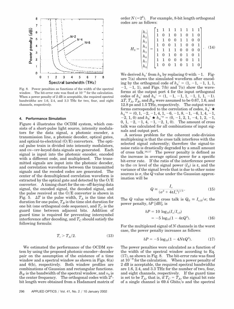
Fig. 8. Power penalties as functions of the width of the spectralwindow. The bit-error rate was fixed at 10�9 for the calculation.When a power penalty of 2 dB is acceptable, the required spectralbandwidths are 1.6, 2.4, and 3.3 THz for two, four, and eightchannels, respectively.
96 APPLIED OPTICS � Vol. 41, No. 2 � 10 January 2002
order N ��2k�. For example, 8-bit length orthogonalcodes are as follows:
H8 � �h1
h2
h3
h4
h5
h6
h7
h8
� � 1 1 1 1 1 1 1 11 0 1 0 1 0 1 01 1 0 0 1 1 0 01 0 0 1 1 0 0 11 1 1 1 0 0 0 01 0 1 0 0 1 0 11 1 0 0 0 0 1 11 0 0 1 0 1 1 0
. (14)
We derived hk� from hk by replacing 0 with �1. Fig-ure 7�a� shows the simulated waveform after encod-ing by the orthogonal code of h4� � �1, �1, �1, 1, 1,�1, �1, 1�, and Figs. 7�b� and 7�c� show the wave-forms at the output port 4 for the input orthogonalcodes of h4� and h8� � �1, �1, �1, 1, �1, 1, 1, �1�.�T, TA, TB, and BW were assumed to be 0.67, 1.6, and12.8 ps and 1.5 THz, respectively. The output wave-forms corresponded to the correlation of codes, h4� �h4�* � �0, 1, �2, �1, 4, 1, �6, �1, 8, �1, �6, 1, 4, �1,�2, 1, 0� and h8� � h4�* � �0, �1, 2, 1, �4, 1, 2, �1,0, 1, �2, �1, 4, �1, �2, 1, 0�. The amount of crosstalk was calculated for all combinations of input sig-nals and output port.
A serious problem for the coherent code-divisionmultiplexing is that the cross talk interferes with theselected signal coherently; therefore the signal-to-noise ratio is drastically degraded by a small amountof cross talk.16,17 The power penalty is defined asthe increase in average optical power for a specificbit-error rate. If the ratio of the interference powerto the ON level of the signal power �IS� is ε, and thevariance of the signal levels that is due to other noisesources is �, the Q value under the Gaussian approx-imation will be
Q �Is
��2 � 4εIs2�1�2 . (15)
The Q value without cross talk is Q0 � Is,0��; thepower penalty, �P dB�, is
�P � 10 log10�Is�Is,0�
� �5 log10�1 � 4εQ2�. (16)
For the multiplexed signal of N channels in the worstcase, the power penalty increases as follows:
�P � �5 log10�1 � 4NεQ2�. (17)
The power penalties were calculated as a function ofthe width of the spectral window according to Eq.�17�, as shown in Fig. 8. The bit-error rate was fixedat 10�9 for the calculation. When a power penalty of2 dB is acceptable, the required spectral bandwidthsare 1.6, 2.4, and 3.3 THz for the number of two, four,and eight channels, respectively. If the guard timeis set to be TA, that is, if TC � TA, the signal bit rateof a single channel is 69.4 Gbits�s and the spectral

efficiencies are 0.087, 0.12, 0.17 �bits�s��Hz when thenumber of channels is two, four, and eight, respec-tively.
5. Conclusions
We have proposed a photonic encoder–decoder pairfor a time-domain optical code-division multiplexingsystem. Without precise control, the encoder cangenerate optical orthogonal codes that are recorded ina hologram and can multiplex those codes from eachinput port. The decoder generates the correlationwaveform between the input code and the recordedcode and demultiplexes input signals with differentcodes into different output ports.
The origin of cross talk is imperfect orthogonalitythat is due to the time window and the spectral win-dow of the dispersive element. The spectral effi-ciency of the OCDM with the proposed device wasdetermined by the cross talk. The simulated resultsindicate that a spectral efficiency of �0.17 �bits�s��Hz at a bit-error rate of 10�9 would be obtained for8-bit length orthogonal signals in the worst case.This value is almost the same value as that of recentWDM systems �10 Gbits�s with 50-GHz spacing or 40Gbits�s with 200-GHz spacing�. Therefore the pro-posed OCDM can be used to configure a more-flexiblenetwork in combination with other multiplexingschemes.
For long orthogonal signals, such as those with 32or more bits per signal, the high signal-to-noise ratiocan be obtained by use of three-dimensional orienta-tion, as shown in Fig. 2. One can maintain the crosstalk that is due to imperfect orthogonality at a lowerlevel by broadening the widths of the time windowand the spectral window according to the lengths ofthe codes. The main problem in using a long code isthat the dispersion of the transmission fiber shouldbe accurately compensated for owing to the presenceof a wider bandwidth for a given bit rate. Thereforea long optical code �many multiplexing channels� isnot practical for use in a backbone network but issuitable for a subscriber network because the lengthof the fiber is usually a mile or less. Furthermore,the OCDMA system in a subscriber network requiresa terminal encoder to distinguish whether the inputsignal is matched, so only one code is recorded in thehologram.
This research was supported by research grantsfrom the Matsuda Foundation, the U.S.–Japan JointOptoelectronics Project �Real World Computing Part-nership�, and the Casio Science Promotion Founda-tion. We are grateful to T. Kurokawa of the TokyoUniversity of Agriculture & Technology for fruitful
discussions.References1. A. M. Weiner, J. P. Heritage, and J. A. Salehi, “Encoding and
decoding of femtosecond pulses,” Opt. Lett. 13, 300–302�1988�.
2. J. A. Salehi, A. M. Weiner, and J. P. Heritage, “Coherentultrashort light pulse code-division multiple access communi-cation systems,” J. Lightwave Technol. 8, 478–491 �1990�.
3. H. P. Sardesai, C.-C. Chang, and A. M. Weiner, “A femtosecondcode-division multiple access communication system test bed,”J. Lightwave Technol. 16, 1953–1964 �1998�.
4. P. R. Prucnal, M. A. Santoro, and S. K. Sehgal, “Ultrafastall-optical synchronous multiple access fiber networks,” IEEEJ. Sel. Areas Commun. SAC-4, 1484–1493 �1986�.
5. J. Nishikido, M. Okuno, and A. Himeno, “4.65 Gbit�s opticalfour-bit pattern matching using silica-based waveguide cir-cuit,” Electron. Lett. 26, 1766–1767 �1990�.
6. R. A. Griffin, D. D. Sampson, and D. A. Jackson, “Optical phasecoding for code-division multiple access networks,” IEEE Pho-ton. Technol. Lett. 4, 1401–1404 �1992�.
7. N. Wada and K. Kitayama, “A 10 Gb�s optical code divisionmultiplexing using 8-chip optical bipolar code and coherentdetection,” J. Lightwave Technol. 17, 1758–1765 �1999�.
8. Y. T. Mazurenko, “Detection and reconstruction of ultrashortpulses by interference of spectrally dispersed light,” Sov. J.Quantum Electron. 15, 815–818 �1985�.
9. Y. T. Mazurenko, “Interference of spectrally dispersed light,”Opt. Spectrosc. �USSR� 56, 357 �1984�.
10. T. Kurokawa, H. Tsuda, K. Okamoto, K. Naganuma, H. Take-nouchi, Y. Inoue, and M. Ishii, “Time–space-conversion opticalsignal processing using arrayed-waveguide grating,” Electron.Lett. 33, 1890–1891 �1997�.
11. H. Tsuda, H. Takenouchi, A. Hirano, T. Kurokawa, and K.Okamoto, “Performance analysis of a dispersion compensatorusing arrayed-waveguide gratings,” J. Lightwave Technol. 18,1139–1147 �2000�.
12. H. Tsuda, H. Takenouchi, T. Ishii, K. Okamoto, T. Goh, K.Sato, A. Hirano, T. Kurokawa, and C. Amano, “Photonic spec-tral encoder�decoder using an arrayed-waveguide grating forcoherent optical code division multiplexing,” in WDM Compo-nents, D. A. Nolan, ed., Vol. 29 of OSA Trends in Optics andPhotonics Series �Optical Society of America, Washington,D.C., 1999�, pp. 206–212.
13. H. Tsuda, H. Takenouchi, T. Ishii, K. Okamoto, T. Goh, K.Sato, A. Hirano, T. Kurokawa, and C. Amano, “Spectral en-coding of 10 Gbit�s femtosecond pulses using a high resolutionarrayed-waveguide grating,” Electron. Lett. 35, 1186–1188�1999�.
14. M. C. Bashaw, J. F. Heanue, A. Aharoni, J. F. Walkup, and L.Hesselink, “Cross-talk considerations for angular and phase-encoded multiplexing in volume holography,” J. Opt. Soc. Am.B 11, 1820–1835 �1994�.
15. J. E. Ford, Y. Fainman, and S. H. Lee, “Reconfigurable arrayinterconnection by photorefractive correlation,” Appl. Opt. 33,5363–5377 �1994�.
16. J. L. Gimlett and N. K. Cheung, “Effects of phase-to-intensitynoise conversion by multiple reflections on gigabit-per-secondDFB laser transmission systems,” J. Lightwave Technol. 7,888–895 �1989�.
17. E. L. Goldstein, L. Eskildsen, and A. F. Elrefaie, “Performanceimplications of component crosstalk in transparent lightwavenetworks,” IEEE Photon. Technol. Lett. 6, 657–660 �1994�.
10 January 2002 � Vol. 41, No. 2 � APPLIED OPTICS 297
![Donut PCR: a rapid, portable, multiplexed, and ... · 24/04/2020 · but low multiplexing platforms (qPCR [7, 8] and isothermal amplification [9, 10]). Two notable exceptions to](https://img.pdfslide.us/doc/110x75/5f87cc4751b4e01afa751a94/donut-pcr-a-rapid-portable-multiplexed-and-24042020-but-low-multiplexing.jpg)