Embed Size (px)
Citation preview
photon science2010ªHighlights and HASYLAB Annual Report
Accelerators | Photon Science | Particle Physics
Deutsches Elektronen-Synchrotron
A Research Centre of the Helmholtz Association
Imprintpublishing and contact:Hamburger Synchrotronstrahlungslabor HASYLABat Deutsches Elektronen-Synchrotron DESYA Research Centre of the Helmholtz AssociationNotkestr. 85D-22607 HAMBURG, Germany
Phone: +49 40 8998-2304Fax: +49 40 8998-4475
E-mail: [email protected]. and hasylab.desy.de
ISBN 978-3-935702-50-8
online version:hasylab.desy.de/annual_report
Realisation:Wiebke Laasch, Ralf Röhlsberger
editing:Stefan Düsterer, Rainer Gehrke, Heinz Graafsma, Christian Gutt, Wiebke Laasch, Wolfgang Morgenroth, Ralf Röhlsberger, Ulla Vainio, Martin von Zimmermann
Layout: Britta Liebaug, Heike Becker
printing: Heigener Europrint GmbH, Hamburg
copy deadline: December 2010
Reproduction including extracts is permitted subject to crediting the source.
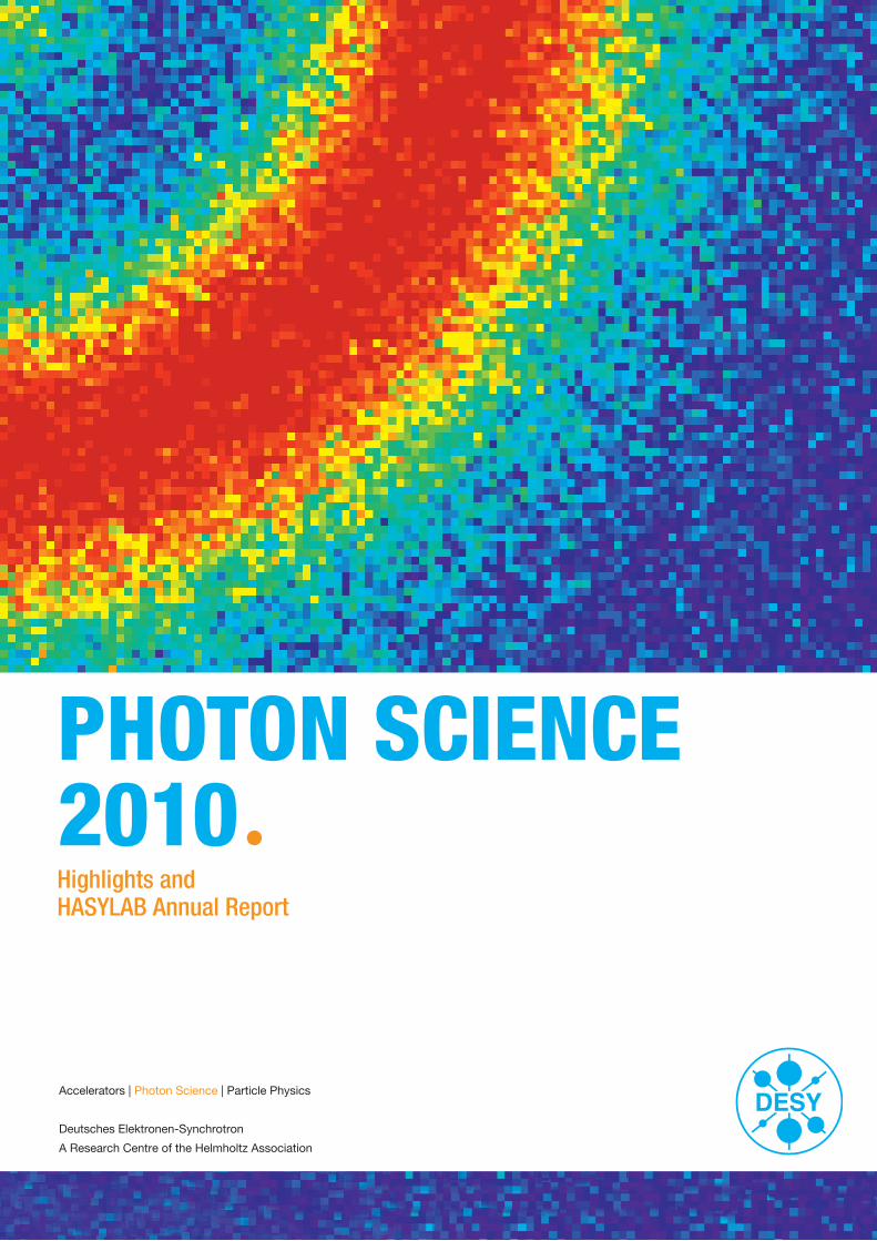
CoverMagnetic small angle scattering pattern of a Co/Pt multilayer recorded with a single 30 fs FLASH pulse. The photon energy was in resonance with the Co M2,3 edge at 20.8 nm. More information about this measurement can be found in the contribution “Femtosecond snapshots of magnetic domains” on page 26.
Highlights and HASYLAB Annual Report
photon science2010ª

2 | Contents
Contents | 3
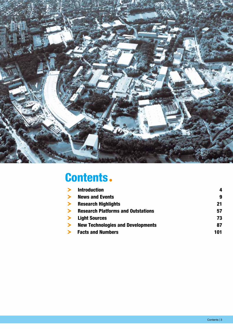
contentsªº introduction 4º news and events 9º Research highlights 21º Research platforms and outstations 57º Light sources 73º new technologies and Developments 87º Facts and numbers 101
4 | Introduction
50 years ago, on 16 May 1960, Theodore H. Maiman at Hughes Research Labs announced a breakthrough in photon science: the construction of the first optical laser, which produced red light at 694 nm. Since then, lasers have revolutionised our world in a similar way to integrated circuits, with both technologies belonging to the high-tech strategy of every modern society.
50 years later, researchers have made another bold leap into the future: the extension of lasers into the X-ray regime by the FEL principle. At DESY, the first test facility “TTF-1” demon-strated in early 2000 the feasibility of so-called SASE-FELs in the VUV range, and then showed saturation in September 2001. This pioneering work carried out by DESY has sparked a world-wide boom in FEL research. TTF-1 has turned into the FEL user facility FLASH, which has demonstrated FEL user operation for many years while pushing the FEL limits forward, making headlines with new performance records almost every year.
Today, in 2010, the world-wide FEL race is in full swing. FLASH operates now at 4.12 nm wavelength and thus allows ultrafast science in the magic “water window”. The European XFEL is in its second year of construction, while the LCLS at Stanford has started operation at 1 angstrom wavelength and has de-livered in recent months the first breathtaking insights into the new world of ultrafast phenomena with angstrom resolution.
For the European XFEL and its shareholders the message is clear: FEL technology is a moving target, expanding its parameter space continuously. Thus, in order to ensure that the European XFEL will be the world’s best X-ray FEL when it is switched on in 2014, we cannot afford to make any compromises about its technical scope, performance and schedule. We must push for the ultimate technology, even if it is costly, and deliver the world’s best facility without any delays in construction and commissioning.
There is a consensus among the experts world-wide that the most clever photon science strategy is to pursue the complemen tary development of highly brilliant synchrotron radiation facilities and XFEL sources—covering all the expected needs in the future exploration of nanospace at all relevant length and time
the year 2010 at DesYªChairman’s foreword
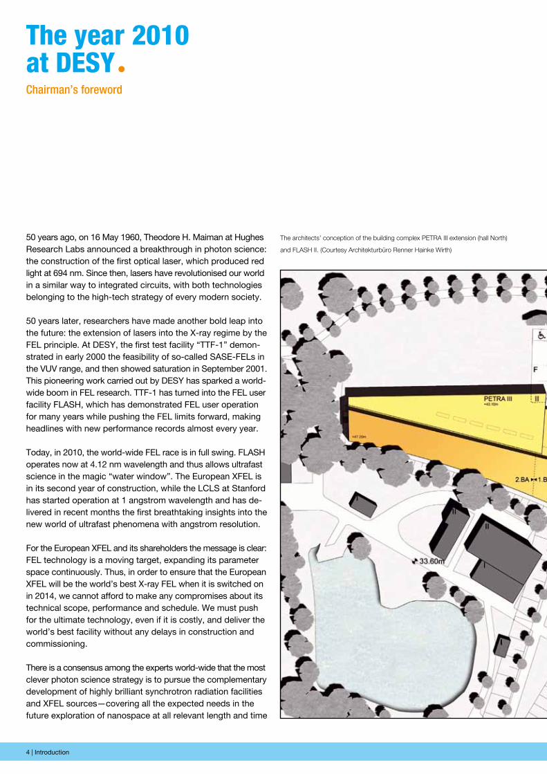
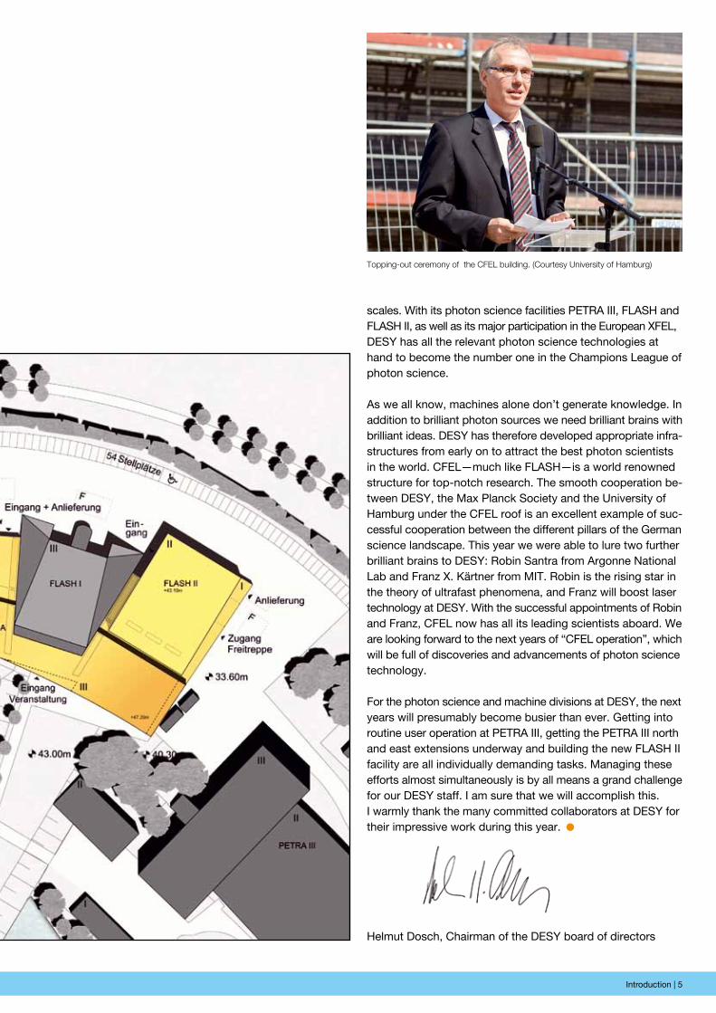
The architects’ conception of the building complex PETRA III extension (hall North)
and FLASH II. (Courtesy Architekturbüro Renner Hainke Wirth)
Introduction | 5
scales. With its photon science facilities PETRA III, FLASH and FLASH II, as well as its major participation in the European XFEL, DESY has all the relevant photon science technologies at hand to become the number one in the Champions League of photon science.
As we all know, machines alone don’t generate knowledge. In addition to brilliant photon sources we need brilliant brains with brilliant ideas. DESY has therefore developed appropriate infra-structures from early on to attract the best photon scientists in the world. CFEL—much like FLASH—is a world renowned structure for top-notch research. The smooth cooperation be-tween DESY, the Max Planck Society and the University of Ham burg under the CFEL roof is an excellent example of suc-cessful cooperation between the different pillars of the German science landscape. This year we were able to lure two further brilliant brains to DESY: Robin Santra from Argonne National Lab and Franz X. Kärtner from MIT. Robin is the rising star in the theory of ultra fast phenomena, and Franz will boost laser technology at DESY. With the successful appointments of Robin and Franz, CFEL now has all its leading scientists aboard. We are looking forward to the next years of “CFEL operation”, which will be full of discoveries and advancements of photon science technology.
For the photon science and machine divisions at DESY, the next years will presumably become busier than ever. Getting into routine user operation at PETRA III, getting the PETRA III north and east exten sions underway and building the new FLASH II facility are all individually demanding tasks. Managing these efforts almost simultaneously is by all means a grand challenge for our DESY staff. I am sure that we will accomplish this.I warmly thank the many committed collaborators at DESY for their impressive work during this year.ª
Helmut Dosch, Chairman of the DESY board of directors
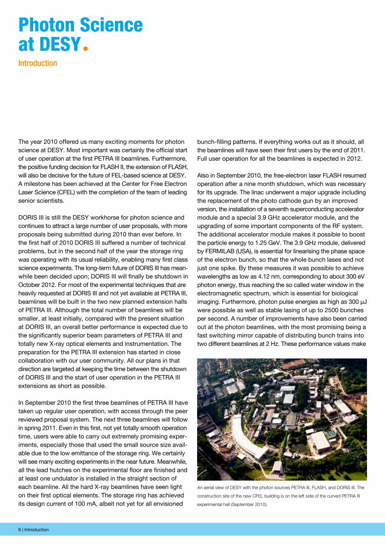
Topping-out ceremony of the CFEL building. (Courtesy University of Hamburg)
6 | Introduction
bunch-filling patterns. If everything works out as it should, all the beamlines will have seen their first users by the end of 2011. Full user operation for all the beamlines is expected in 2012.
Also in September 2010, the free-electron laser FLASH resumed operation after a nine month shutdown, which was necessary for its upgrade. The linac underwent a major upgrade including the replacement of the photo cathode gun by an improved version, the installation of a seventh superconducting accelerator module and a special 3.9 GHz accelerator module, and the upgrading of some important components of the RF system. The additional accelerator module makes it possible to boost the particle energy to 1.25 GeV. The 3.9 GHz module, delivered by FERMILAB (USA), is essential for linearising the phase space of the electron bunch, so that the whole bunch lases and not just one spike. By these measures it was possible to achieve wavelengths as low as 4.12 nm, corresponding to about 300 eV photon energy, thus reaching the so called water window in the electromagnetic spectrum, which is essential for biological imaging. Furthermore, photon pulse energies as high as 300 µJ were possible as well as stable lasing of up to 2500 bunches per second. A number of improvements have also been carried out at the photon beamlines, with the most promising being a fast switching mirror capable of distributing bunch trains into two different beamlines at 2 Hz. These performance values make
The year 2010 offered us many exciting moments for photon science at DESY. Most important was certainly the official start of user operation at the first PETRA III beamlines. Furthermore, the positive funding decision for FLASH II, the extension of FLASH, will also be decisive for the future of FEL-based science at DESY. A milestone has been achieved at the Center for Free Electron Laser Science (CFEL) with the completion of the team of leading senior scientists.
DORIS III is still the DESY workhorse for photon science and continues to attract a large number of user proposals, with more proposals being submitted during 2010 than ever before. In the first half of 2010 DORIS III suffered a number of technical problems, but in the second half of the year the storage ring was operating with its usual reliability, enabling many first class science experiments. The long-term future of DORIS III has mean-while been decided upon; DORIS III will finally be shutdown in October 2012. For most of the experimental techniques that are heavily requested at DORIS III and not yet available at PETRA III, beamlines will be built in the two new planned extension halls of PETRA III. Although the total number of beamlines will be smaller, at least initially, compared with the present situation at DORIS III, an overall better performance is expected due to the significantly superior beam parameters of PETRA III and totally new X-ray optical elements and instrumentation. The preparation for the PETRA III extension has started in close collaboration with our user community. All our plans in that direction are targeted at keeping the time between the shutdown of DORIS III and the start of user operation in the PETRA III extensions as short as possible.
In September 2010 the first three beamlines of PETRA III have taken up regular user operation, with access through the peer reviewed proposal system. The next three beamlines will follow in spring 2011. Even in this first, not yet totally smooth operation time, users were able to carry out extremely promising exper-iments, especially those that used the small source size avail-able due to the low emittance of the storage ring. We certainly will see many exciting experiments in the near future. Meanwhile, all the lead hutches on the experimental floor are finished and at least one undulator is installed in the straight section of each beamline. All the hard X-ray beamlines have seen light on their first optical elements. The storage ring has achieved its design current of 100 mA, albeit not yet for all envisioned
photon science at DesYªIntroduction
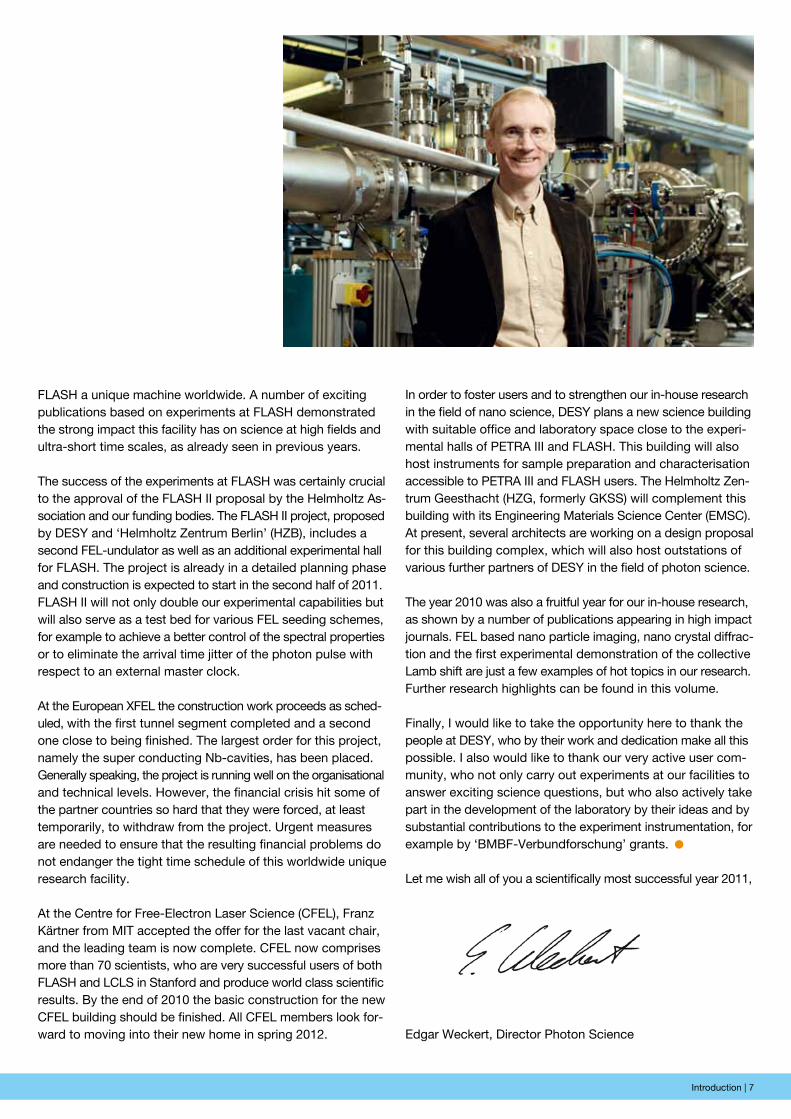
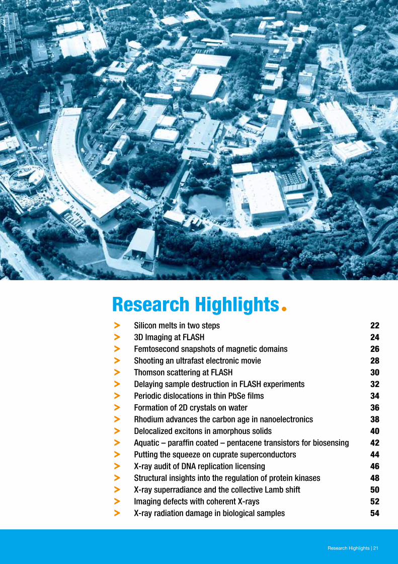
An aerial view of DESY with the photon sources PETRA III, FLASH, and DORIS III. The
construction site of the new CFEL building is on the left side of the curved PETRA III
experimental hall (September 2010).
Introduction | 7
FLASH a unique machine worldwide. A number of exciting publications based on experiments at FLASH demonstrated the strong impact this facility has on science at high fields and ultra-short time scales, as already seen in previous years.
The success of the experiments at FLASH was certainly crucial to the approval of the FLASH II proposal by the Helmholtz As-sociation and our funding bodies. The FLASH II project, proposed by DESY and ‘Helmholtz Zentrum Berlin’ (HZB), includes a second FEL-undulator as well as an additional experimental hall for FLASH. The project is already in a detailed planning phase and construction is expected to start in the second half of 2011. FLASH II will not only double our experimental capabilities but will also serve as a test bed for various FEL seeding schemes, for example to achieve a better control of the spectral properties or to eliminate the arrival time jitter of the photon pulse with respect to an external master clock.
At the European XFEL the construction work proceeds as sched-uled, with the first tunnel segment completed and a second one close to being finished. The largest order for this project, namely the super conducting Nb-cavities, has been placed. Generally speaking, the project is running well on the organisational and technical levels. However, the financial crisis hit some of the partner countries so hard that they were forced, at least temporarily, to withdraw from the project. Urgent measures are needed to ensure that the resulting financial problems do not endanger the tight time schedule of this worldwide unique research facility.
At the Centre for Free-Electron Laser Science (CFEL), Franz Kärtner from MIT accepted the offer for the last vacant chair, and the leading team is now complete. CFEL now comprises more than 70 scientists, who are very successful users of both FLASH and LCLS in Stanford and produce world class scientific results. By the end of 2010 the basic construction for the new CFEL building should be finished. All CFEL members look for-ward to moving into their new home in spring 2012.
In order to foster users and to strengthen our in-house research in the field of nano science, DESY plans a new science building with suitable office and laboratory space close to the experi-mental halls of PETRA III and FLASH. This building will also host instruments for sample preparation and characterisation accessible to PETRA III and FLASH users. The Helmholtz Zen-trum Geesthacht (HZG, formerly GKSS) will complement this building with its Engineering Materials Science Center (EMSC). At present, several architects are working on a design proposal for this building complex, which will also host outstations of various further partners of DESY in the field of photon science.
The year 2010 was also a fruitful year for our in-house research, as shown by a number of publications appearing in high impact journals. FEL based nano particle imaging, nano crystal diffrac-tion and the first experimental demonstration of the collective Lamb shift are just a few examples of hot topics in our research. Further research highlights can be found in this volume.
Finally, I would like to take the opportunity here to thank the people at DESY, who by their work and dedication make all this possible. I also would like to thank our very active user com-munity, who not only carry out experiments at our facilities to answer exciting science questions, but who also actively take part in the development of the laboratory by their ideas and by substantial contributions to the experiment instrumentation, for example by ‘BMBF-Verbundforschung’ grants.ª
Let me wish all of you a scientifically most successful year 2011,
Edgar Weckert, Director Photon Science

8 | News and Events

News and Events | 9
news and eventsª
10 | News and Events
January
January 26: peak Brightness collaboration Meeting
The “Peak Brightness Collaboration on FLASH Experiments” was formed in 2002 on the occasion of the first call for proposals for the new soft X-ray FEL user facility. The scientific topics of this international collaboration are related to the investigation of dense matter and biological samples under extreme conditions. Investigated systems include solids exposed by focused FEL radiation or plasmas generated by intense optical laser radiation. Within the collaboration also physical processes are investigated which are of importance to the quest for biological imaging. In 2010, two meetings were held in January and September. During these half-day meetings at each occasion over fifty scientists from more than ten countries met at DESY to review the results of recent experiments at FLASH and at LCLS, to discuss ideas for the next experiments, possibilities of future collaboration, and to gather information about upcoming activities at future FEL facilities, e.g. the FLASH II facility, the HED (high-energy density) station at European XFEL and the MEC station (matter at extreme conditions) at LCLS.
news and eventsªA busy year 2010
The audience seemed to appreciate the fact that all sessions left ample time for discussions and questions. The active participation of the attendees in the discussions, in the lecture hall as well as outside, during the poster session and the breaks, was very stimulating.
January 27: Joint european XFeL and hAsYLAB Users’ Meeting
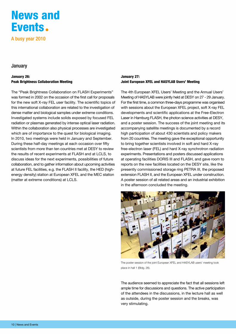
The 4th European XFEL Users’ Meeting and the Annual Users’ Meeting of HASYLAB were jointly held at DESY on 27 - 29 January. For the first time, a common three-days programme was organised with sessions about the European XFEL project, soft X-ray FEL developments and scientific applications at the Free-Electron Laser in Hamburg FLASH, the photon science activities at DESY, and a poster session. The success of the joint meeting and its accompanying satellite meetings is documented by a record high participation of about 430 scientists and policy makers from 20 countries. The meeting gave the exceptional opportunity to bring together scientists involved in soft and hard X-ray free-electron laser (FEL) and hard X-ray synchrotron radiation experiments. Presentations and posters discussed applications at operating facilities DORIS III and FLASH, and gave room to reports on the new facilities located on the DESY site, like the presently commissioned storage ring PETRA III, the proposed extension FLASH II, and the European XFEL under construction. A poster session of all related areas and an industrial exhibition in the afternoon concluded the meeting.
The poster session of the joint European XFEL and HASYLAB users’ meeting took
place in hall 1 (Bldg. 26).
News and Events | 11
March
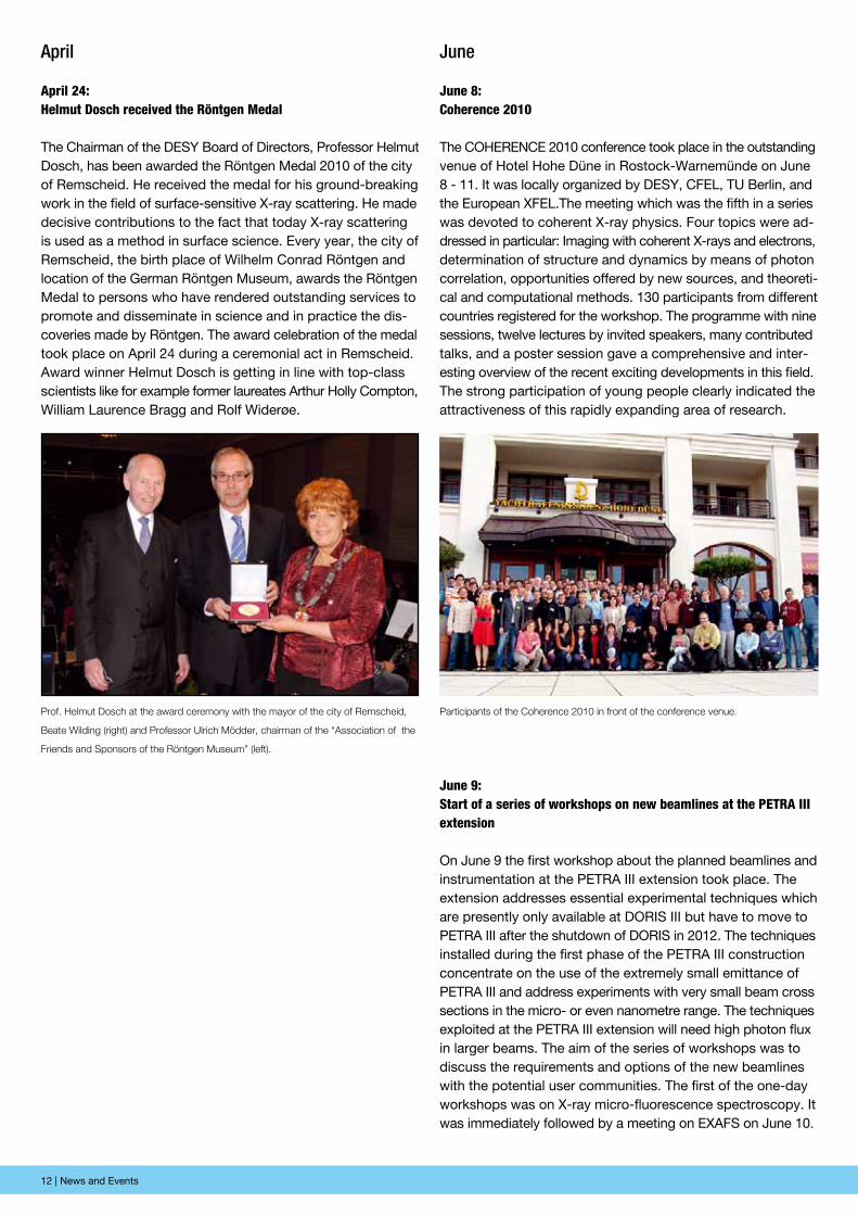
March 29: Workshop on synchrotron Radiation for Bio-imaging at petRA iii
The workshop was intended to bring scientists from bio-medical backgrounds together with synchrotron staff to establish a new interdisciplinary user community around the new high resolution bio-imaging beamlines P06 and P11 at PETRA III. The workshop attracted more than 50 participants. Twenty speakers from ten countries reported on their actual research and perspectives by using X-ray techniques. This was an ex-cellent opportunity for a hands-on introduction into the new possibilities for bio-imaging on the micro- and especially nano-scale at this facility. Furthermore new experiments and collab-orations as well as future developments or requirements from the users were discussed. Scientists from the PETRA III bio-imaging group presented possibilities at beamlines P06 and P11: In-situ measurements using non-invasive preparation of bio-logical samples, under cryogenic conditions with high brilliance micro- and nano-beams and high resolution down to about 10 nm, by using X-ray fluorescence, X-ray absorption and phase contrast, X-ray absorption spectroscopy and X-ray dif-fraction for 2D mapping and 3D tomography. The community discussed important issues of sample preparation and on-site data analysis.
Disordered Materials in Synchrotron and XFEL X-ray lightªIX. Research Course on New X-Ray SciencesFebruary 17-19, 2010 at DESY Hamburg
http://hasylab.desy.de/course2010
Accelerators | Photon Science | Particle Physics
Deutsches Elektronen-SynchrotronA Research Centre of the Helmholtz Association
Speakers:L. Cipelletti (University Montpellier), H. Franz (DESY), D.K. Saldin (University Wisconsin), A. Nilsson (Stanford), P. Wochner (MPI Stuttgart), O. Shpyrko (UC San Diego), G. Monaco (ESRF), G. Ruocco (University Rome), J. Roth (Univer-sity Stuttgart), R. Röhlsberger (DESY), H. Sinn (European-XFEL)
ORGANIZING COMMITTEE: C. Gutt (DESY), G. Grübel (DESY) and HASYLAB [email protected]
Free-electron laser for short wavelength radiation and the latest generation of storage rings for the generation of hard X-ray synchrotron radiation are new light sources providing extremely high brilliance radiation. These novel sources allow for new experimental techniques, therefore enabling new scienti c results. The DESY course shall provide basic knowledge about new directions of X-ray research and address Diploma (Master), PhD student and young research fellows. Detailed information about the program and how to apply can be found on the web.The 9th course is dedicated to the structure and dynamics of disordered materials using the properties of highly brilliant X-ray sources. Modern experimental techniques and scienti c applications will be discussed.
The number of participants is limited. Applications for this course should be made no later than January 22, 2010.
º Structure and Dynamics of Liquids and Glasses
º Challenges in Disordered Materials
º New Theoretical Developments
º Coherent X-ray Scattering
º Surfaces of Disordered Materials
º Disorder in Soft Materials
º New X-ray Sources for Disordered Systems
February
February 17: iX. Research course on new X-ray science - Disordered materials
The aim of the periodic DESY research courses is to provide basic knowledge about new directions of X-ray research to Diploma (Master) and PhD students and to young research fellows. The 9th course of this series was dedicated to the in-vestigation of structural and dynamical properties of disordered materials using the properties of highly brilliant X-ray sources. Modern experimental techniques and scientific applications were introduced and discussed covering topics like structure and dynamics of liquids and glasses, challenges in disordered materials, new theoretical developments, opportunities with coherent X-rays, surfaces of disordered materials, and disorder in soft matter.
50 participants attended the Workshop on Synchrotron Radiation for Bio-Imaging at PETRA III.
12 | News and Events
April
April 24: helmut Dosch received the Röntgen Medal
The Chairman of the DESY Board of Directors, Professor Helmut Dosch, has been awarded the Röntgen Medal 2010 of the city of Remscheid. He received the medal for his ground-breaking work in the field of surface-sensitive X-ray scattering. He made decisive contributions to the fact that today X-ray scattering is used as a method in surface science. Every year, the city of Remscheid, the birth place of Wilhelm Conrad Röntgen and location of the German Röntgen Museum, awards the Röntgen Medal to persons who have rendered outstanding services to promote and disseminate in science and in practice the dis-coveries made by Röntgen. The award celebration of the medal took place on April 24 during a ceremonial act in Remscheid. Award winner Helmut Dosch is getting in line with top-class scientists like for example former laureates Arthur Holly Compton, William Laurence Bragg and Rolf Widerøe.
June
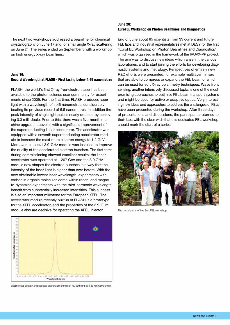
June 8: coherence 2010
The COHERENCE 2010 conference took place in the outstanding venue of Hotel Hohe Düne in Rostock-Warnemünde on June 8 - 11. It was locally organized by DESY, CFEL, TU Berlin, and the European XFEL.The meeting which was the fifth in a series was devoted to coherent X-ray physics. Four topics were ad-dressed in particular: Imaging with coherent X-rays and electrons, determination of structure and dynamics by means of photon correlation, opportunities offered by new sources, and theoreti-cal and computational methods. 130 participants from different countries registered for the workshop. The programme with nine sessions, twelve lectures by invited speakers, many contributed talks, and a poster session gave a comprehensive and inter-esting overview of the recent exciting developments in this field. The strong participation of young people clearly indicated the attractiveness of this rapidly expanding area of research.
Participants of the Coherence 2010 in front of the conference venue.Prof. Helmut Dosch at the award ceremony with the mayor of the city of Remscheid,
Beate Wilding (right) and Professor Ulrich Mödder, chairman of the “Association of the
Friends and Sponsors of the Röntgen Museum” (left).
June 9: start of a series of workshops on new beamlines at the petRA iii extension
On June 9 the first workshop about the planned beamlines and instrumentation at the PETRA III extension took place. The extension addresses essential experimental techniques which are presently only available at DORIS III but have to move to PETRA III after the shutdown of DORIS in 2012. The techniques installed during the first phase of the PETRA III construction concentrate on the use of the extremely small emittance of PETRA III and address experiments with very small beam cross sections in the micro- or even nanometre range. The techniques exploited at the PETRA III extension will need high photon flux in larger beams. The aim of the series of workshops was to discuss the requirements and options of the new beamlines with the potential user communities. The first of the one-day workshops was on X-ray micro-fluorescence spectroscopy. It was immediately followed by a meeting on EXAFS on June 10.
News and Events | 13
The participants of the EuroFEL workshop.
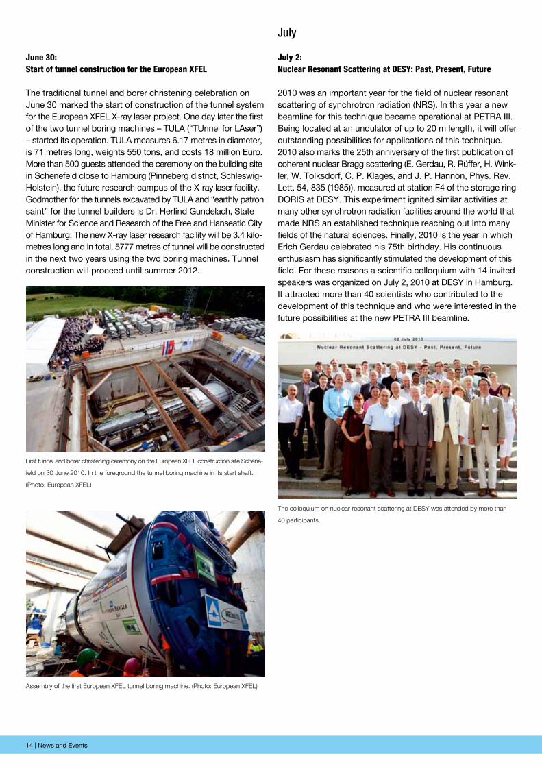
Beam cross section and spectral distribution of the first FLASH light at 4.45 nm wavelength.
The next two workshops addressed a beamline for chemical crystallography on June 17 and for small angle X-ray scattering on June 24. The series ended on September 8 with a workshop on high energy X-ray beamlines.
June 16: Record Wavelength at FLAsh - First lasing below 4.45 nanometres
FLASH, the world’s first X-ray free-electron laser has been available to the photon science user community for experi-ments since 2005. For the first time, FLASH produced laser light with a wavelength of 4.45 nanometres, considerably beating its previous record of 6.5 nanometres. In addition the peak intensity of single light pulses nearly doubled by achiev-ing 0.3 milli-Joule. Prior to this, there was a five-month ma-chine upgrade, above all with a significant improvement of the superconducting linear accelerator. The accelerator was equipped with a seventh superconducting accelerator mod-ule to increase the maxi-mum electron energy to 1.2 GeV. Moreover, a special 3.9-GHz module was installed to improve the quality of the accelerated electron bunches. The first tests during commissioning showed excellent results: the linear accelerator was operated at 1.207 GeV and the 3.9 GHz module now shapes the electron bunches in a way that the intensity of the laser light is higher than ever before. With the now obtainable lowest laser wavelength, experiments with carbon in organic molecules come within reach, and magne-to-dynamics experiments with the third-harmonic wavelength benefit from substantially increased intensities. This success is also an important milestone for the European XFEL. The accelerator module recently built-in at FLASH is a prototype for the XFEL accelerator, and the properties of the 3.9-GHz module also are decisive for operating the XFEL injector.
June 28: euroFeL Workshop on photon Beamlines and Diagnostics
End of June about 85 scientists from 33 current and future FEL labs and industrial representatives met at DESY for the first “EuroFEL Workshop on Photon Beamlines and Diagnostics” which was organised in the framework of the IRUVX-PP project. The aim was to discuss new ideas which arise in the various laboratories, and to start joining the efforts for developing diag-nostic systems and metrology. Perspectives of entirely new R&D efforts were presented, for example multilayer mirrors that are able to compress or expand the FEL beam or which can be used for soft X-ray polarimetry techniques. Wave front sensing, another intensively discussed topic, is one of the most promising approaches to optimise FEL beam transport systems and might be used for active or adaptive optics. Very interest-ing new ideas and approaches to address the challenges of FELs have been presented during the workshop. After three days of presentations and discussions, the participants returned to their labs with the clear wish that this dedicated FEL workshop should mark the start of a series.
14 | News and Events
June 30: start of tunnel construction for the european XFeL
The traditional tunnel and borer christening celebration on June 30 marked the start of construction of the tunnel system for the European XFEL X-ray laser project. One day later the first of the two tunnel boring machines – TULA (“TUnnel for LAser”) – started its operation. TULA measures 6.17 metres in diameter, is 71 metres long, weights 550 tons, and costs 18 million Euro. More than 500 guests attended the ceremony on the building site in Schenefeld close to Hamburg (Pinneberg district, Schles wig-Holstein), the future research campus of the X-ray laser facility. Godmother for the tunnels excavated by TULA and “earthly patron saint” for the tunnel builders is Dr. Herlind Gundelach, State Minister for Science and Research of the Free and Hanseatic City of Hamburg. The new X-ray laser research facility will be 3.4 kilo-metres long and in total, 5777 metres of tunnel will be construc ted in the next two years using the two boring machines. Tunnel construction will proceed until summer 2012.
First tunnel and borer christening ceremony on the European XFEL construction site Schene-
feld on 30 June 2010. In the foreground the tunnel boring machine in its start shaft.
(Photo: European XFEL)
The colloquium on nuclear resonant scattering at DESY was attended by more than
40 participants.
Assembly of the first European XFEL tunnel boring machine. (Photo: European XFEL)
July
July 2: nuclear Resonant scattering at DesY: past, present, Future
2010 was an important year for the field of nuclear resonant scattering of synchrotron radiation (NRS). In this year a new beamline for this technique became operational at PETRA III. Being located at an undulator of up to 20 m length, it will offer outstanding possibilities for applications of this technique. 2010 also marks the 25th anniversary of the first publication of coherent nuclear Bragg scattering (E. Gerdau, R. Rüffer, H. Wink-ler, W. Tolksdorf, C. P. Klages, and J. P. Hannon, Phys. Rev. Lett. 54, 835 (1985)), measured at station F4 of the storage ring DORIS at DESY. This experiment ignited similar activities at many other synchrotron radiation facilities around the world that made NRS an established technique reaching out into many fields of the natural sciences. Finally, 2010 is the year in which Erich Gerdau celebrated his 75th birthday. His continuous enthusiasm has significantly stimulated the development of this field. For these reasons a scientific colloquium with 14 invited speakers was organized on July 2, 2010 at DESY in Hamburg. It attracted more than 40 scientists who contributed to the development of this technique and who were interested in the future possibilities at the new PETRA III beamline.
News and Events | 15
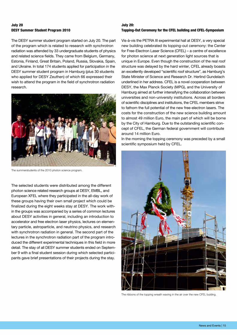
The summerstudents of the 2010 photon science program.
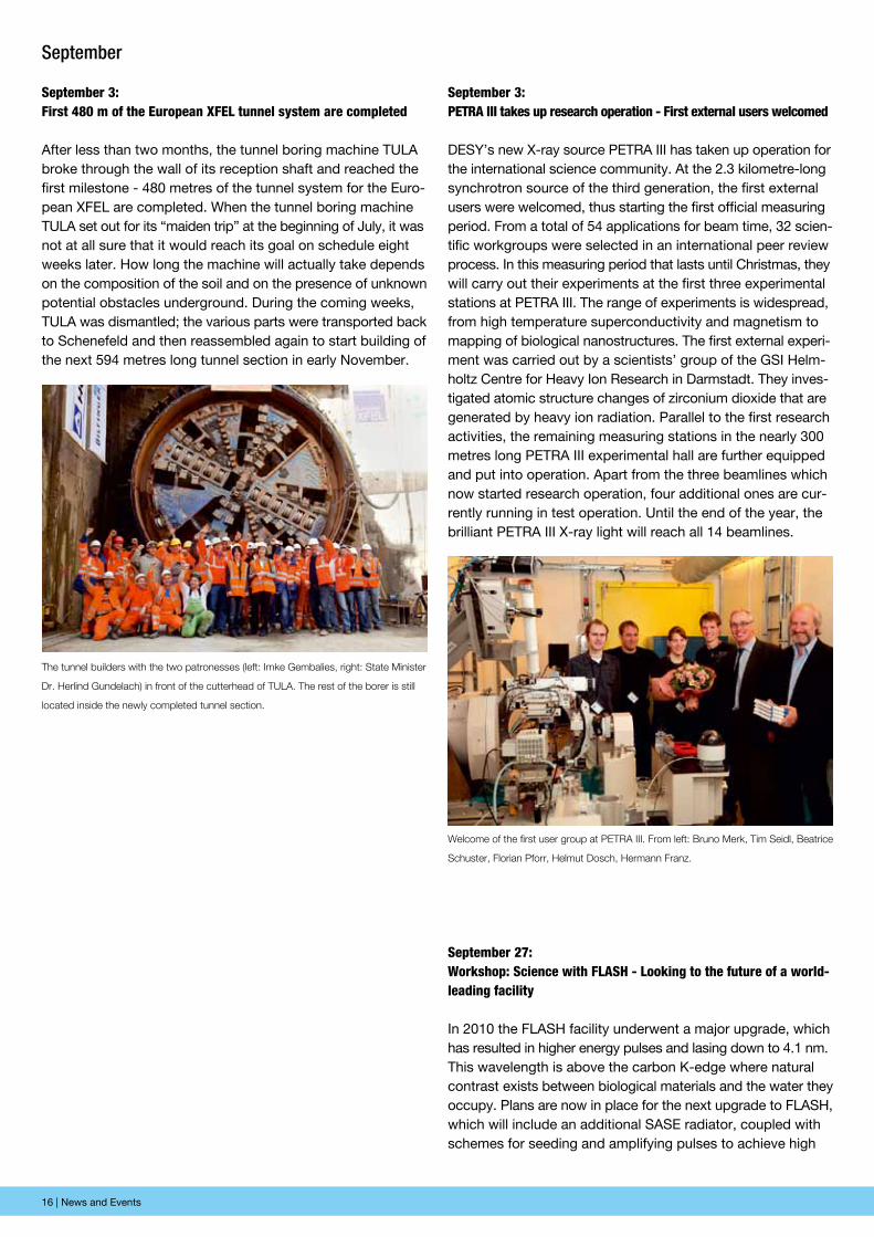
The ribbons of the topping wreath waving in the air over the new CFEL bulding.
July 20DesY summer student program 2010
The DESY summer student program started on July 20. The part of the program which is related to research with synchrotron radiation was attended by 33 undergraduate students of physics and related science fields. They came from Belgium, Germany, Estonia, Finland, Great Britain, Poland, Russia, Slovakia, Spain, and Ukraine. In total 174 students applied for participation in the DESY summer student program in Hamburg (plus 30 students who applied for DESY Zeuthen) of which 66 expressed their wish to attend the program in the field of synchrotron radiation research.
The selected students were distributed among the different photon science related research groups at DESY, EMBL, and Euro pean XFEL where they participated in the all-day work of these groups having their own small project which could be finalized during the eight weeks stay at DESY. The work with-in the groups was accompanied by a series of common lectures about DESY activities in general, including an introduction to accelerator and free electron laser physics, lectures on elemen-tary particle, astroparticle, and neutrino physics, and research with synchrotron radiation in general. The second part of the lectures in the synchrotron radiation part of the program intro-duced the different experimental techniques in this field in more detail. The stay of all DESY summer students ended on Septem-ber 9 with a final student session during which selected partici-pants gave brief presentations of their projects during the stay.
July 20: topping-out ceremony for the cFeL building and cFeL-symposium
Vis-à-vis the PETRA III experimental hall at DESY, a very special new building celebrated its topping-out ceremony: the Center for Free-Electron Laser Science (CFEL) – a centre of excellence for photon science at next generation light sources that is unique in Europe. Even though the construction of the real roof structure was delayed by the hard winter, CFEL already boasts an excellently developed “scientific roof structure”, as Hamburg’s State Minister of Science and Research Dr. Herlind Gundelach underlined in her address. CFEL is a novel cooperation between DESY, the Max Planck Society (MPG), and the University of Hamburg aimed at further intensifying the collaboration between universities and non-university institutions. Across all borders of scientific disciplines and institutions, the CFEL members strive to fathom the full potential of the new free-electron lasers. The costs for the construction of the new science building amount to almost 49 million Euro, the main part of which will be borne by the City of Hamburg. Due to the outstanding scientific con-cept of CFEL, the German federal government will contribute around 14 million Euro.In the morning the topping ceremony was preceded by a small scientific symposium held by CFEL.
16 | News and Events
September
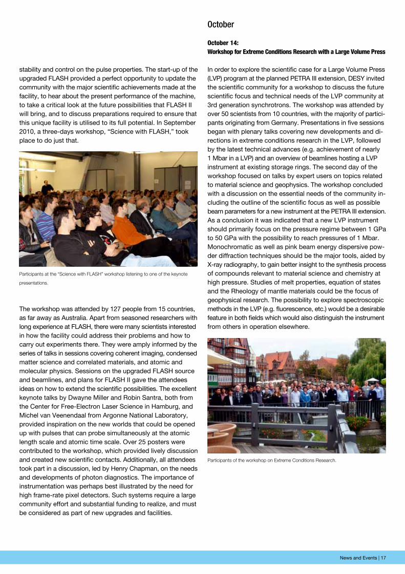
september 3: First 480 m of the european XFeL tunnel system are completed
After less than two months, the tunnel boring machine TULA broke through the wall of its reception shaft and reached the first milestone - 480 metres of the tunnel system for the Euro-pean XFEL are completed. When the tunnel boring machine TULA set out for its “maiden trip” at the beginning of July, it was not at all sure that it would reach its goal on schedule eight weeks later. How long the machine will actually take depends on the composition of the soil and on the presence of unknown potential obstacles underground. During the coming weeks, TULA was dismantled; the various parts were transported back to Schenefeld and then reassembled again to start building of the next 594 metres long tunnel section in early November.
The tunnel builders with the two patronesses (left: Imke Gembalies, right: State Minister
Dr. Herlind Gundelach) in front of the cutterhead of TULA. The rest of the borer is still
located inside the newly completed tunnel section.
Welcome of the first user group at PETRA III. From left: Bruno Merk, Tim Seidl, Beatrice
Schuster, Florian Pforr, Helmut Dosch, Hermann Franz.
september 3: petRA iii takes up research operation - First external users welcomed
DESY’s new X-ray source PETRA III has taken up operation for the international science community. At the 2.3 kilometre-long synchrotron source of the third generation, the first external users were welcomed, thus starting the first official measuring period. From a total of 54 applications for beam time, 32 scien-tific workgroups were selected in an international peer review process. In this measuring period that lasts until Christmas, they will carry out their experiments at the first three experimental stations at PETRA III. The range of experiments is widespread, from high temperature superconductivity and magnetism to mapping of biological nanostructures. The first external experi-ment was carried out by a scientists’ group of the GSI Helm-holtz Centre for Heavy Ion Research in Darmstadt. They inves-tigated atomic structure changes of zirconium dioxide that are generated by heavy ion radiation. Parallel to the first research activities, the remaining measuring stations in the nearly 300 metres long PETRA III experimental hall are further equipped and put into operation. Apart from the three beamlines which now started research operation, four additional ones are cur-rently running in test operation. Until the end of the year, the brilliant PETRA III X-ray light will reach all 14 beamlines.
september 27: Workshop: science with FLAsh - Looking to the future of a world-leading facility
In 2010 the FLASH facility underwent a major upgrade, which has resulted in higher energy pulses and lasing down to 4.1 nm. This wavelength is above the carbon K-edge where natural contrast exists between biological materials and the water they occupy. Plans are now in place for the next upgrade to FLASH, which will include an additional SASE radiator, coupled with schemes for seeding and amplifying pulses to achieve high
News and Events | 17
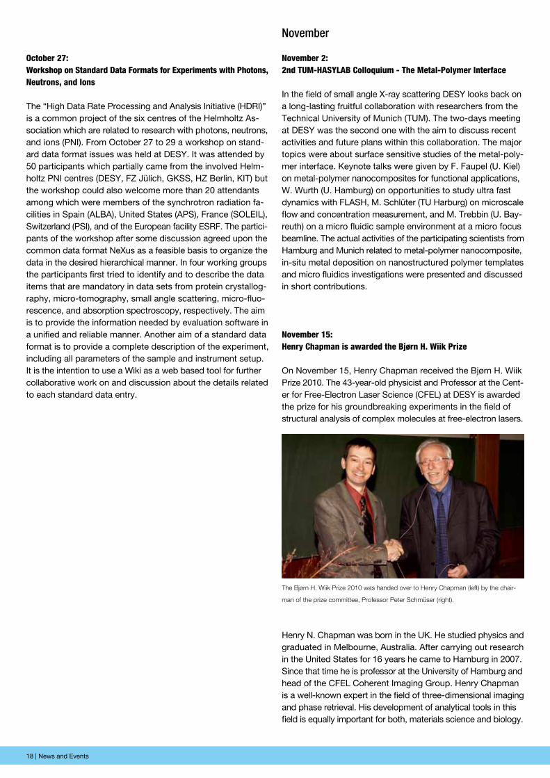
Participants at the “Science with FLASH” workshop listening to one of the keynote
presentations.
Participants of the workshop on Extreme Conditions Research.
stability and control on the pulse properties. The start-up of the upgraded FLASH provided a perfect opportunity to update the community with the major scientific achievements made at the facility, to hear about the present performance of the machine, to take a critical look at the future possibilities that FLASH II will bring, and to discuss preparations required to ensure that this unique facility is utilised to its full potential. In September 2010, a three-days workshop, “Science with FLASH,” took place to do just that.
The workshop was attended by 127 people from 15 countries, as far away as Australia. Apart from seasoned researchers with long experience at FLASH, there were many scientists interested in how the facility could address their problems and how to carry out experiments there. They were amply informed by the series of talks in sessions covering coherent imaging, condensed matter science and correlated materials, and atomic and mole cular physics. Sessions on the upgraded FLASH source and beamlines, and plans for FLASH II gave the attendees ideas on how to extend the scientific possibilities. The excellent keynote talks by Dwayne Miller and Robin Santra, both from the Center for Free-Electron Laser Science in Hamburg, and Michel van Veenendaal from Argonne National Laboratory, provided inspiration on the new worlds that could be opened up with pulses that can probe simultaneously at the atomic length scale and atomic time scale. Over 25 posters were contributed to the workshop, which provided lively discussion and created new scientific contacts. Additionally, all attendees took part in a discussion, led by Henry Chapman, on the needs and develop ments of photon diagnostics. The importance of instrumentation was perhaps best illustrated by the need for high frame-rate pixel detectors. Such systems require a large community effort and substantial funding to realize, and must be considered as part of new upgrades and facilities.
October
october 14: Workshop for extreme conditions Research with a Large Volume press
In order to explore the scientific case for a Large Volume Press (LVP) program at the planned PETRA III extension, DESY invited the scientific community for a workshop to discuss the future scientific focus and technical needs of the LVP community at 3rd generation synchrotrons. The workshop was attended by over 50 scientists from 10 countries, with the majority of partici-pants originating from Germany. Presentations in five sessions began with plenary talks covering new developments and di-rections in extreme conditions research in the LVP, followed by the latest technical advances (e.g. achievement of nearly 1 Mbar in a LVP) and an overview of beamlines hosting a LVP instrument at existing storage rings. The second day of the workshop focused on talks by expert users on topics related to material science and geophysics. The workshop concluded with a discussion on the essential needs of the community in-cluding the outline of the scientific focus as well as possible beam parameters for a new instrument at the PETRA III extension. As a conclusion it was indicated that a new LVP instrument should primarily focus on the pressure regime between 1 GPa to 50 GPa with the possibility to reach pressures of 1 Mbar. Monochromatic as well as pink beam energy dispersive pow-der diffraction techniques should be the major tools, aided by X-ray radiography, to gain better insight to the synthesis process of compounds relevant to material science and chemistry at high pressure. Studies of melt properties, equation of states and the Rheology of mantle materials could be the focus of geophysical research. The possibility to explore spectroscopic methods in the LVP (e.g. fluorescence, etc.) would be a desirable feature in both fields which would also distinguish the instrument from others in operation elsewhere.
18 | News and Events
october 27: Workshop on standard Data Formats for experiments with photons, neutrons, and ions
The “High Data Rate Processing and Analysis Initiative (HDRI)” is a common project of the six centres of the Helmholtz As-sociation which are related to research with photons, neutrons, and ions (PNI). From October 27 to 29 a workshop on stand-ard data format issues was held at DESY. It was attended by 50 participants which partially came from the involved Helm-holtz PNI centres (DESY, FZ Jülich, GKSS, HZ Berlin, KIT) but the workshop could also welcome more than 20 attendants among which were members of the synchrotron radiation fa-cilities in Spain (ALBA), United States (APS), France (SOLEIL), Switzerland (PSI), and of the European facility ESRF. The partici-pants of the workshop after some discussion agreed upon the common data format NeXus as a feasible basis to organize the data in the desired hierarchical manner. In four working groups the participants first tried to identify and to describe the data items that are mandatory in data sets from protein crystallog-raphy, micro-tomography, small angle scattering, micro-fluo-rescence, and absorption spectroscopy, respectively. The aim is to provide the information needed by evaluation software in a unified and reliable manner. Another aim of a standard data format is to provide a complete description of the experiment, including all parameters of the sample and instrument setup. It is the intention to use a Wiki as a web based tool for further collaborative work on and discussion about the details related to each standard data entry.
November
november 2: 2nd tUM-hAsYLAB colloquium - the Metal-polymer interface
In the field of small angle X-ray scattering DESY looks back on a long-lasting fruitful collaboration with researchers from the Technical University of Munich (TUM). The two-days meeting at DESY was the second one with the aim to discuss recent activities and future plans within this collaboration. The major topics were about surface sensitive studies of the metal-poly-mer interface. Keynote talks were given by F. Faupel (U. Kiel) on metal-polymer nanocomposites for functional applications, W. Wurth (U. Hamburg) on opportunities to study ultra fast dynamics with FLASH, M. Schlüter (TU Harburg) on microscale flow and concentration measurement, and M. Trebbin (U. Bay-reuth) on a micro fluidic sample environment at a micro focus beamline. The actual activities of the participating scientists from Hamburg and Munich related to metal-polymer nanocomposite, in-situ metal deposition on nanostructured polymer templates and micro fluidics investigations were presented and discussed in short contributions.
november 15:henry chapman is awarded the Bjørn h. Wiik prize
On November 15, Henry Chapman received the Bjørn H. Wiik Prize 2010. The 43-year-old physicist and Professor at the Cent-er for Free-Electron Laser Science (CFEL) at DESY is awarded the prize for his groundbreaking experiments in the field of structural analysis of complex molecules at free-electron lasers.
The Bjørn H. Wiik Prize 2010 was handed over to Henry Chapman (left) by the chair-
man of the prize committee, Professor Peter Schmüser (right).
Henry N. Chapman was born in the UK. He studied physics and graduated in Melbourne, Australia. After carrying out research in the United States for 16 years he came to Hamburg in 2007. Since that time he is professor at the University of Hamburg and head of the CFEL Coherent Imaging Group. Henry Chapman is a well-known expert in the field of three-dimensional imaging and phase retrieval. His development of analytical tools in this field is equally important for both, materials science and biology.
News and Events | 19
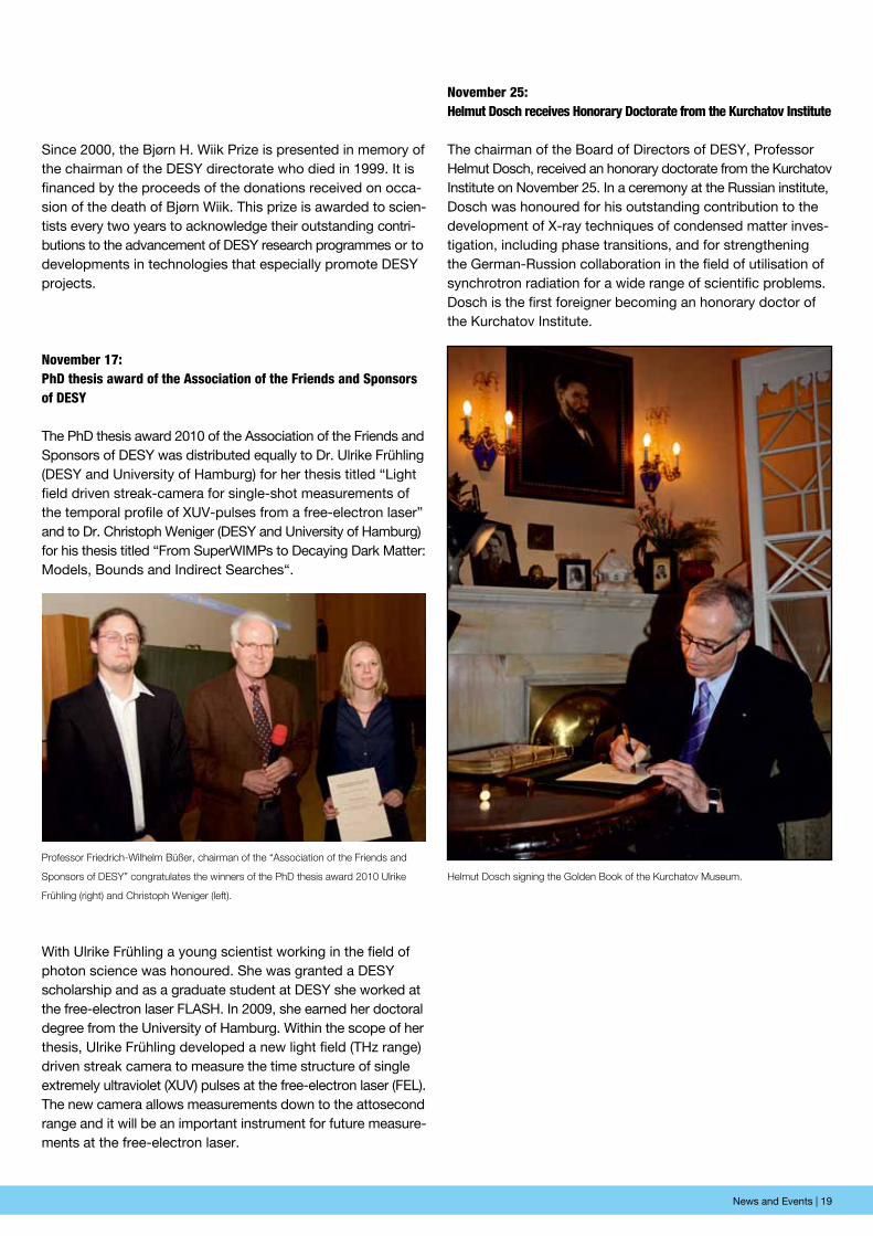
Professor Friedrich-Wilhelm Büßer, chairman of the “Association of the Friends and
Sponsors of DESY” congratulates the winners of the PhD thesis award 2010 Ulrike
Frühling (right) and Christoph Weniger (left).
Helmut Dosch signing the Golden Book of the Kurchatov Museum.
Since 2000, the Bjørn H. Wiik Prize is presented in memory of the chairman of the DESY directorate who died in 1999. It is financed by the proceeds of the donations received on occa-sion of the death of Bjørn Wiik. This prize is awarded to scien-tists every two years to acknowledge their outstanding contri-butions to the advancement of DESY research programmes or to developments in technologies that especially promote DESY projects.
november 17:phD thesis award of the Association of the Friends and sponsors of DesY
The PhD thesis award 2010 of the Association of the Friends and Sponsors of DESY was distributed equally to Dr. Ulrike Frühling (DESY and University of Hamburg) for her thesis titled “Light field driven streak-camera for single-shot measurements of the temporal profile of XUV-pulses from a free-electron laser” and to Dr. Christoph Weniger (DESY and University of Hamburg) for his thesis titled “From SuperWIMPs to Decaying Dark Matter: Models, Bounds and Indirect Searches“.
With Ulrike Frühling a young scientist working in the field of photon science was honoured. She was granted a DESY scholarship and as a graduate student at DESY she worked at the free-electron laser FLASH. In 2009, she earned her doctoral degree from the University of Hamburg. Within the scope of her thesis, Ulrike Frühling developed a new light field (THz range) driven streak camera to measure the time structure of single extremely ultra violet (XUV) pulses at the free-electron laser (FEL). The new camera allows measurements down to the attosecond range and it will be an important instrument for future measure-ments at the free-electron laser.
november 25:helmut Dosch receives honorary Doctorate from the Kurchatov institute
The chairman of the Board of Directors of DESY, Professor Helmut Dosch, received an honorary doctorate from the Kurchatov Institute on November 25. In a ceremony at the Russian institute, Dosch was honoured for his outstanding contribution to the development of X-ray techniques of condensed matter inves-tigation, including phase transitions, and for strengthening the German-Russion collaboration in the field of utilisation of synchrotron radiation for a wide range of scientific problems. Dosch is the first foreigner becoming an honorary doctor of the Kurchatov Institute.

20 | Research Highlights
Research highlightsª
Research Highlights | 21
º Silicon melts in two steps 22º 3D Imaging at FLASH 24º Femtosecond snapshots of magnetic domains 26º Shooting an ultrafast electronic movie 28º Thomson scattering at FLASH 30º Delaying sample destruction in FLASH experiments 32º Periodic dislocations in thin PbSe films 34º Formation of 2D crystals on water 36º Rhodium advances the carbon age in nanoelectronics 38º Delocalized excitons in amorphous solids 40º Aquatic – paraffin coated – pentacene transistors for biosensing 42º Putting the squeeze on cuprate superconductors 44º X-ray audit of DNA replication licensing 46º Structural insights into the regulation of protein kinases 48º X-ray superradiance and the collective Lamb shift 50º Imaging defects with coherent X-rays 52º X-ray radiation damage in biological samples 54
22 | News and Events22 | Research Highlights
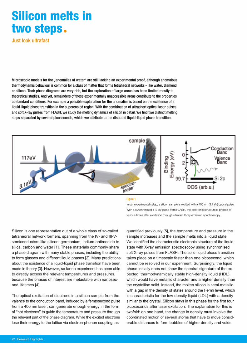
quantified previously [5], the temperature and pressure in the sample increases and the sample melts into a liquid state.We identified the characteristic electronic structure of the liquid state with X-ray emission spectroscopy using synchronised soft X-ray pulses from FLASH. The solid-liquid phase transition takes place on a timescale faster than one picosecond, which cannot be resolved in our experiment. Surprisingly, the liquid phase initially does not show the spectral signature of the ex-pected, thermodynamically stable high-density liquid (HDL), which would have metallic character and a higher density than the crystalline solid. Instead, the molten silicon is semi-metallic with a gap in the density of states around the Fermi level, which is characteristic for the low-density liquid (LDL) with a density similar to the crystal. Silicon stays in this phase for the first four picoseconds after laser excitation. The explanation for this is twofold: on one hand, the change in density must involve the coordinated motion of several atoms that have to move consid-erable distances to form bubbles of higher density and voids
Figure 1
In our experimental setup, a silicon sample is excited with a 400 nm (3.1 eV) optical pulse.
With a synchronised 117 eV pulse from FLASH, the electronic structure is probed at
various times after excitation through ultrafast X-ray emission spectroscopy.
Microscopic models for the „anomalies of water“ are still lacking an experimental proof, although anomalous thermodynamic behaviour is common for a class of matter that forms tetrahedral networks - like water, diamond or silicon. Their phase diagrams are very rich, but the exploration of large areas has been limited mostly to theoretical studies. And yet, remainders of those experimentally unaccessible areas contribute to the properties at standard conditions. For example a possible explanation for the anomalies is based on the existence of a liquid-liquid phase transition in the supercooled region. With the combination of ultrashort optical laser pulses and soft X-ray pulses from FLASH, we study the melting dynamics of silicon in detail. We find two distinct melting steps separated by several picoseconds, which we attribute to the disputed liquid-liquid phase transition.
Silicon is one representative out of a whole class of so-called tetrahedral network formers, spanning from the IV- and III-V-semiconductors like silicon, germanium, indium-antimonide to silica, carbon and water [1]. These materials commonly share a phase diagram with many stable phases, including the ability to form glasses and different liquid phases [2]. Many predictions about the existence of a liquid-liquid phase transition have been made in theory [3]. However, so far no experiment has been able to directly access the relevant temperatures and pressures, because the phases of interest are metastable with nanosec-ond lifetimes [4].
The optical excitation of electrons in a silicon sample from the valence to the conduction band, induced by a femtosecond pulse from a 400 nm laser, can generate enough energy in the form of “hot electrons” to guide the temperature and pressure through the relevant part of the phase diagram. While the excited electrons lose their energy to the lattice via electron-phonon coupling, as
silicon melts intwo stepsªJust look ultrafast
News and Events | 23Research Highlights | 23
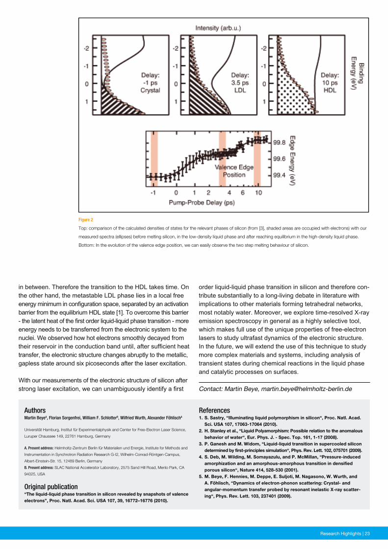
Figure 2
Top: comparison of the calculated densities of states for the relevant phases of silicon (from [3], shaded areas are occupied with electrons) with our
measured spectra (ellipses) before melting silicon, in the low-density liquid phase and after reaching equilibrium in the high-density liquid phase.
Bottom: In the evolution of the valence edge position, we can easily observe the two step melting behaviour of silicon.
References1. S. Sastry, “Illuminating liquid polymorphism in silicon“, Proc. Natl. Acad. Sci. USA 107, 17063-17064 (2010).2. H. Stanley et al., “Liquid Polyamorphism: Possible relation to the anomalous behavior of water“, Eur. Phys. J. - Spec. Top. 161, 1-17 (2008).3. P. Ganesh and M. Widom, “Liquid-liquid transition in supercooled silicon determined by first-principles simulation“, Phys. Rev. Lett. 102, 075701 (2009).4. S. Deb, M. Wilding, M. Somayazulu, and P. McMillan, “Pressure-induced amorphization and an amorphous-amorphous transition in densified porous silicon“, Nature 414, 528-530 (2001).5. M. Beye, F. Hennies, M. Deppe, E. Suljoti, M. Nagasono, W. Wurth, and A. Föhlisch, “Dynamics of electron-phonon scattering: Crystal- and angular-momentum transfer probed by resonant inelastic X-ray scatter- ing“, Phys. Rev. Lett. 103, 237401 (2009).
AuthorsMartin BeyeA, Florian Sorgenfrei, William F. SchlotterB, Wilfried Wurth, Alexander FöhlischA
Universität Hamburg, Institut für Experimentalphysik and Center for Free-Electron Laser Science,
Luruper Chaussee 149, 22761 Hamburg, Germany
A. Present address: Helmholtz-Zentrum Berlin für Materialien und Energie, Institute for Methods and
Instrumentation in Synchrotron Radiation Research G-I2, Wilhelm-Conrad-Röntgen-Campus,
Albert-Einstein-Str. 15, 12489 Berlin, Germany
B. Present address: SLAC National Accelerator Laboratory, 2575 Sand Hill Road, Menlo Park, CA
94025, USA
Original publication“The liquid-liquid phase transition in silicon revealed by snapshots of valence electrons”, Proc. Natl. Acad. Sci. USA 107, 39, 16772–16776 (2010).
in between. Therefore the transition to the HDL takes time. On the other hand, the metastable LDL phase lies in a local free energy minimum in configuration space, separated by an activation barrier from the equilibrium HDL state [1]. To overcome this barrier - the latent heat of the first order liquid-liquid phase transition - more energy needs to be transferred from the electronic system to the nuclei. We observed how hot electrons smoothly decayed from their reservoir in the conduction band until, after sufficient heat transfer, the electronic structure changes abruptly to the metallic, gapless state around six picoseconds after the laser excitation.
With our measurements of the electronic structure of silicon after strong laser excitation, we can unambiguously identify a first Contact: Martin Beye, [email protected]
order liquid-liquid phase transition in silicon and therefore con-tribute substantially to a long-living debate in literature with implications to other materials forming tetrahedral networks, most notably water. Moreover, we explore time-resolved X-ray emission spectroscopy in general as a highly selective tool, which makes full use of the unique properties of free-electron lasers to study ultrafast dynamics of the electronic structure. In the future, we will extend the use of this technique to study more complex materials and systems, including analysis of transient states during chemical reactions in the liquid phase and catalytic processes on surfaces.
24 | News and Events24 | Research Highlights
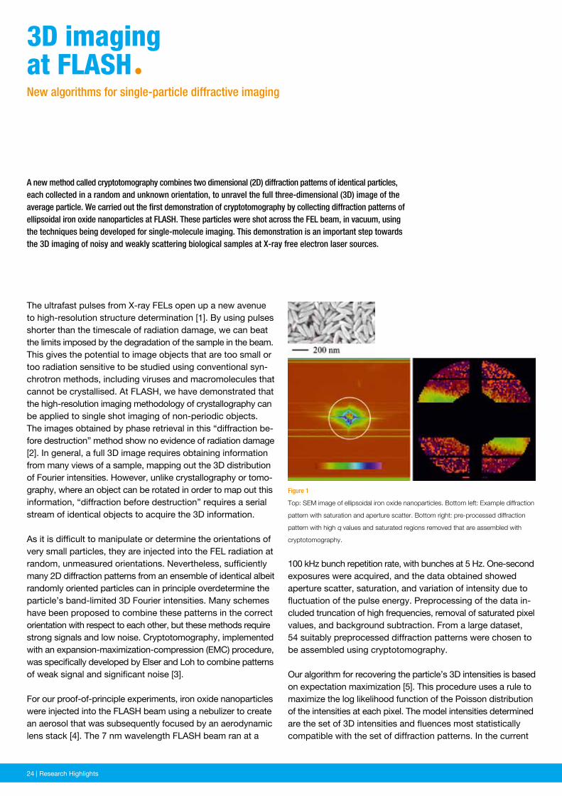
100 kHz bunch repetition rate, with bunches at 5 Hz. One-second exposures were acquired, and the data obtained showed aperture scatter, saturation, and variation of intensity due to fluctuation of the pulse energy. Preprocessing of the data in-cluded truncation of high frequencies, removal of saturated pixel values, and background subtraction. From a large dataset, 54 suitably preprocessed diffraction patterns were chosen to be assembled using cryptotomography.
Our algorithm for recovering the particle’s 3D intensities is based on expectation maximization [5]. This procedure uses a rule to maximize the log likelihood function of the Poisson distribution of the intensities at each pixel. The model intensities determined are the set of 3D intensities and fluences most statistically compatible with the set of diffraction patterns. In the current
Figure 1
Top: SEM image of ellipsoidal iron oxide nanoparticles. Bottom left: Example diffraction
pattern with saturation and aperture scatter. Bottom right: pre-processed diffraction
pattern with high q values and saturated regions removed that are assembled with
cryptotomography.
A new method called cryptotomography combines two dimensional (2D) diffraction patterns of identical particles, each collected in a random and unknown orientation, to unravel the full three-dimensional (3D) image of the average particle. We carried out the first demonstration of cryptotomography by collecting diffraction patterns of ellipsoidal iron oxide nanoparticles at FLASH. These particles were shot across the FEL beam, in vacuum, using the techniques being developed for single-molecule imaging. This demonstration is an important step towards the 3D imaging of noisy and weakly scattering biological samples at X-ray free electron laser sources.
The ultrafast pulses from X-ray FELs open up a new avenue to high-resolution structure determination [1]. By using pulses shorter than the timescale of radiation damage, we can beat the limits imposed by the degradation of the sample in the beam. This gives the potential to image objects that are too small or too radiation sensitive to be studied using conventional syn-chrotron methods, including viruses and macromolecules that cannot be crystallised. At FLASH, we have demonstrated that the high-resolution imaging methodology of crystallography can be applied to single shot imaging of non-periodic objects. The images obtained by phase retrieval in this “diffraction be-fore destruction” method show no evidence of radiation damage [2]. In general, a full 3D image requires obtaining information from many views of a sample, mapping out the 3D distrib ution of Fourier intensities. However, unlike crystallography or tomo-graphy, where an object can be rotated in order to map out this information, “diffraction before destruction” requires a serial stream of identical objects to acquire the 3D information.
As it is difficult to manipulate or determine the orientations of very small particles, they are injected into the FEL radiation at random, unmeasured orientations. Nevertheless, sufficiently many 2D diffraction patterns from an ensemble of identical albeit randomly oriented particles can in principle overdetermine the particle’s band-limited 3D Fourier intensities. Many schemes have been proposed to combine these patterns in the correct orientation with respect to each other, but these methods require strong signals and low noise. Cryptotomography, implemented with an expansion-maximization-compression (EMC) procedure, was specifically developed by Elser and Loh to combine patterns of weak signal and significant noise [3].
For our proof-of-principle experiments, iron oxide nanoparticles were injected into the FLASH beam using a nebulizer to create an aerosol that was subsequently focused by an aerodynamic lens stack [4]. The 7 nm wavelength FLASH beam ran at a
3D imaging at FLAshªNew algorithms for single-particle diffractive imaging
News and Events | 25Research Highlights | 25
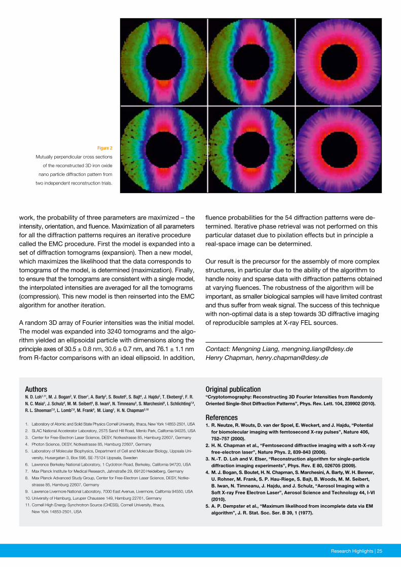
Figure 2
Mutually perpendicular cross sections
of the reconstructed 3D iron oxide
nano particle diffraction pattern from
two independent reconstruction trials.
Original publication“Cryptotomography: Reconstructing 3D Fourier Intensities from Randomly Oriented Single-Shot Diffraction Patterns”, Phys. Rev. Lett. 104, 239902 (2010).
References1. R. Neutze, R. Wouts, D. van der Spoel, E. Weckert, and J. Hajdu, “Potential for biomolecular imaging with femtosecond X-ray pulses”, Nature 406, 752–757 (2000).2. H. N. Chapman et al., “Femtosecond diffractive imaging with a soft-X-ray free-electron laser”, Nature Phys. 2, 839-843 (2006).3. N.-T. D. Loh and V. Elser, “Reconstruction algorithm for single-particle diffraction imaging experiments”, Phys. Rev. E 80, 026705 (2009).4. M. J. Bogan, S. Boutet, H. N. Chapman, S. Marchesini, A. Barty, W. H. Benner, U. Rohner, M. Frank, S. P. Hau-Riege, S. Bajt, B. Woods, M. M. Seibert, B. Iwan, N. Timneanu, J. Hajdu, and J. Schulz, “Aerosol Imaging with a Soft X-ray Free Electron Laser”, Aerosol Science and Technology 44, I-VI (2010).5. A. P. Dempster et al., “Maximum likelihood from incomplete data via EM algorithm”, J. R. Stat. Soc. Ser. B 39, 1 (1977).
AuthorsN. D. Loh1,11, M. J. Bogan2, V. Elser1, A. Barty3, S. Boutet2, S. Bajt4, J. Hajdu5, T. Ekeberg5, F. R. N. C. Maia5, J. Schulz3, M. M. Seibert5, B. Iwan5, N. Timneanu5, S. Marchesini6, I. Schlichting7,8, R. L. Shoeman7,8, L. Lomb7,8, M. Frank9, M. Liang3, H. N. Chapman3,10
1. Laboratory of Atomic and Solid State Physics Cornell University, Ithaca, New York 14853-2501, USA
2. SLAC National Accelerator Laboratory, 2575 Sand Hill Road, Menlo Park, California 94025, USA
3. Center for Free-Electron Laser Science, DESY, Notkestrasse 85, Hamburg 22607, Germany
4. Photon Science, DESY, Notkestrasse 85, Hamburg 22607, Germany
5. Laboratory of Molecular Biophysics, Department of Cell and Molecular Biology, Uppsala Uni-
versity, Husargatan 3, Box 596, SE-75124 Uppsala, Sweden
6. Lawrence Berkeley National Laboratory, 1 Cyclotron Road, Berkeley, California 94720, USA
7. Max Planck Institute for Medical Research, Jahnstraße 29, 69120 Heidelberg, Germany
8. Max Planck Advanced Study Group, Center for Free-Electron Laser Science, DESY, Notke-
strasse 85, Hamburg 22607, Germany
9. Lawrence Livermore National Laboratory, 7000 East Avenue, Livermore, California 94550, USA
10. University of Hamburg, Luruper Chaussee 149, Hamburg 22761, Germany
11. Cornell High Energy Synchrotron Source (CHESS), Cornell University, Ithaca,
New York 14853-2501, USA
work, the probability of three parameters are maximized – the intensity, orientation, and fluence. Maximization of all parameters for all the diffraction patterns requires an iterative procedure called the EMC procedure. First the model is expanded into a set of diffraction tomograms (expansion). Then a new model, which maximizes the likelihood that the data corresponds to tomograms of the model, is determined (maximization). Finally, to ensure that the tomograms are consistent with a single model, the interpolated intensities are averaged for all the tomograms (compression). This new model is then reinserted into the EMC algorithm for another iteration.
A random 3D array of Fourier intensities was the initial model. The model was expanded into 3240 tomograms and the algo-rithm yielded an ellipsoidal particle with dimensions along the principle axes of 30.5 ± 0.8 nm, 30.6 ± 0.7 nm, and 76.1 ± 1.1 nm from R-factor comparisons with an ideal ellipsoid. In addition,
Contact: Mengning Liang, [email protected] Chapman, [email protected]
fluence probabilities for the 54 diffraction patterns were de-termined. Iterative phase retrieval was not performed on this particular dataset due to pixilation effects but in principle a real-space image can be determined.
Our result is the precursor for the assembly of more complex structures, in particular due to the ability of the algorithm to handle noisy and sparse data with diffraction patterns obtained at varying fluences. The robustness of the algorithm will be important, as smaller biological samples will have limited contrast and thus suffer from weak signal. The success of this technique with non-optimal data is a step towards 3D diffractive imaging of reproducible samples at X-ray FEL sources.
26 | News and Events26 | Research Highlights
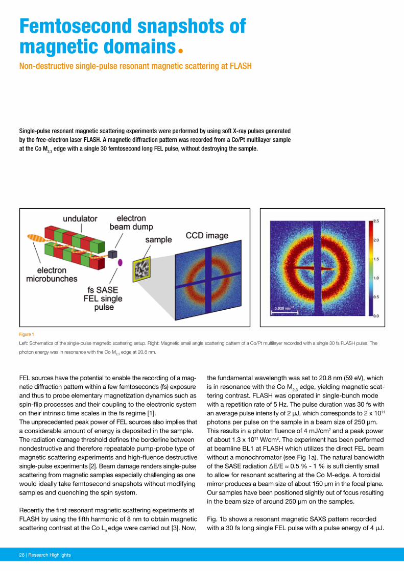
the fundamental wavelength was set to 20.8 nm (59 eV), which is in resonance with the Co M2,3 edge, yielding magnetic scat-tering contrast. FLASH was operated in single-bunch mode with a repetition rate of 5 Hz. The pulse duration was 30 fs with an average pulse intensity of 2 μJ, which corresponds to 2 x 10¹¹ photons per pulse on the sample in a beam size of 250 μm. This results in a photon fluence of 4 mJ/cm2 and a peak power of about 1.3 x 10¹¹ W/cm2. The experiment has been performed at beamline BL1 at FLASH which utilizes the direct FEL beam without a monochromator (see Fig 1a). The natural bandwidth of the SASE radiation ΔE/E ≈ 0.5 % - 1 % is sufficiently small to allow for resonant scattering at the Co M-edge. A toroidal mirror produces a beam size of about 150 μm in the focal plane. Our samples have been positioned slightly out of focus resulting in the beam size of around 250 μm on the samples.
Fig. 1b shows a resonant magnetic SAXS pattern recorded with a 30 fs long single FEL pulse with a pulse energy of 4 μJ.
Figure 1
Left: Schematics of the single-pulse magnetic scattering setup. Right: Magnetic small angle scattering pattern of a Co/Pt multilayer recorded with a single 30 fs FLASH pulse. The
photon energy was in resonance with the Co M2,3 edge at 20.8 nm.
Single-pulse resonant magnetic scattering experiments were performed by using soft X-ray pulses generated by the free-electron laser FLASH. A magnetic diffraction pattern was recorded from a Co/Pt multilayer sample at the Co M2,3 edge with a single 30 femtosecond long FEL pulse, without destroying the sample.
FEL sources have the potential to enable the recording of a mag-netic diffraction pattern within a few femtoseconds (fs) exposure and thus to probe elementary magnetization dynamics such as spin-flip processes and their coupling to the electronic system on their intrinsic time scales in the fs regime [1].The unprecedented peak power of FEL sources also implies that a considerable amount of energy is deposited in the sample. The radiation damage threshold defines the borderline between nondestructive and therefore repeatable pump-probe type of magnetic scattering experiments and high-fluence destructive single-pulse experiments [2]. Beam damage renders single-pulse scattering from magnetic samples especially challenging as one would ideally take femtosecond snapshots without modifying samples and quenching the spin system.
Recently the first resonant magnetic scattering experiments at FLASH by using the fifth harmonic of 8 nm to obtain magnetic scattering contrast at the Co L3 edge were carried out [3]. Now,
Femtosecond snapshots ofmagnetic domainsªNon-destructive single-pulse resonant magnetic scattering at FLASH
News and Events | 27Research Highlights | 27
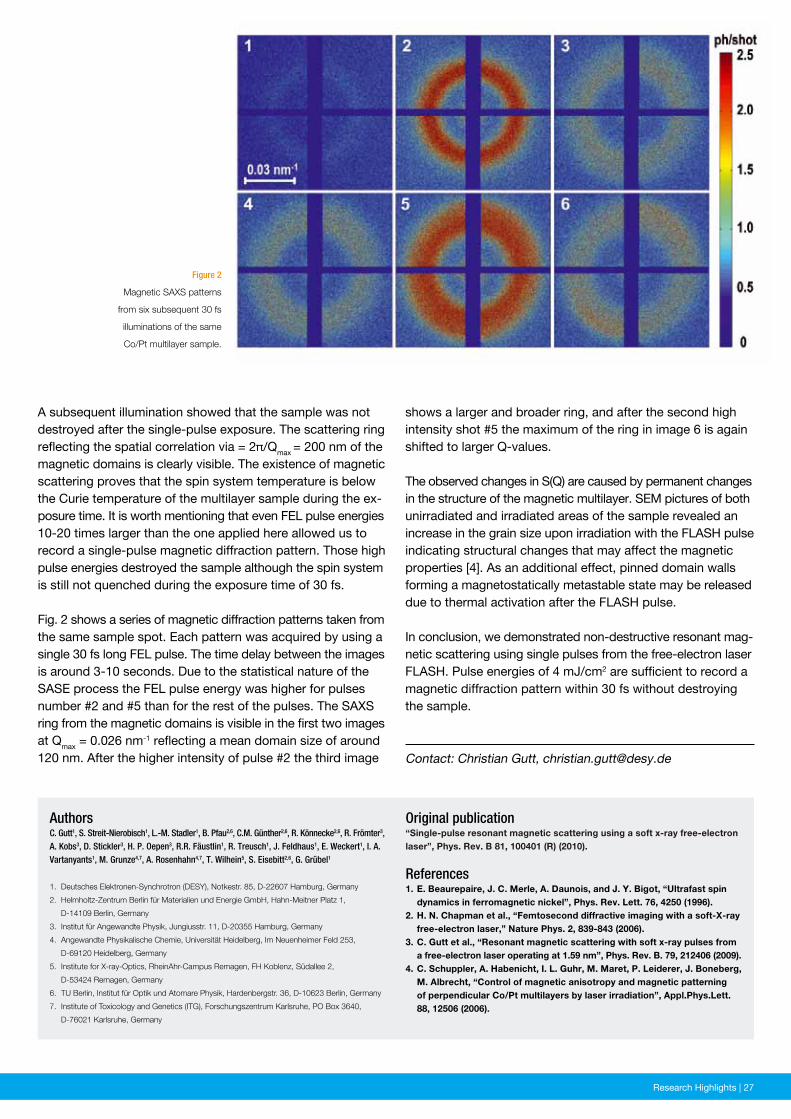
Figure 2
Magnetic SAXS patterns
from six subsequent 30 fs
illuminations of the same
Co/Pt multilayer sample.
Original publication“Single-pulse resonant magnetic scattering using a soft x-ray free-electron laser”, Phys. Rev. B 81, 100401 (R) (2010).
References1. E. Beaurepaire, J. C. Merle, A. Daunois, and J. Y. Bigot, “Ultrafast spin dynamics in ferromagnetic nickel”, Phys. Rev. Lett. 76, 4250 (1996).2. H. N. Chapman et al., “Femtosecond diffractive imaging with a soft-X-ray free-electron laser,” Nature Phys. 2, 839-843 (2006).3. C. Gutt et al., “Resonant magnetic scattering with soft x-ray pulses from a free-electron laser operating at 1.59 nm”, Phys. Rev. B. 79, 212406 (2009).4. C. Schuppler, A. Habenicht, I. L. Guhr, M. Maret, P. Leiderer, J. Boneberg, M. Albrecht, “Control of magnetic anisotropy and magnetic patterning of perpendicular Co/Pt multilayers by laser irradiation”, Appl.Phys.Lett. 88, 12506 (2006).
AuthorsC. Gutt1, S. Streit-Nierobisch1, L.-M. Stadler1, B. Pfau2,6, C.M. Günther2,6, R. Könnecke2,6, R. Frömter3, A. Kobs3, D. Stickler3, H. P. Oepen3, R.R. Fäustlin1, R. Treusch1, J. Feldhaus1, E. Weckert1, I. A. Vartanyants1, M. Grunze4,7, A. Rosenhahn4,7, T. Wilhein5, S. Eisebitt2,6, G. Grübel1
1. Deutsches Elektronen-Synchrotron (DESY), Notkestr. 85, D-22607 Hamburg, Germany
2. Helmholtz-Zentrum Berlin für Materialien und Energie GmbH, Hahn-Meitner Platz 1,
D-14109 Berlin, Germany
3. Institut für Angewandte Physik, Jungiusstr. 11, D-20355 Hamburg, Germany
4. Angewandte Physikalische Chemie, Universität Heidelberg, Im Neuenheimer Feld 253,
D-69120 Heidelberg, Germany
5. Institute for X-ray-Optics, RheinAhr-Campus Remagen, FH Koblenz, Südallee 2,
D-53424 Remagen, Germany
6. TU Berlin, Institut für Optik und Atomare Physik, Hardenbergstr. 36, D-10623 Berlin, Germany
7. Institute of Toxicology and Genetics (ITG), Forschungszentrum Karlsruhe, PO Box 3640,
D-76021 Karlsruhe, Germany
A subsequent illumination showed that the sample was not destroyed after the single-pulse exposure. The scattering ring reflecting the spatial correlation via = 2π/Qmax = 200 nm of the magnetic domains is clearly visible. The existence of magnetic scattering proves that the spin system temperature is below the Curie temperature of the multilayer sample during the ex-posure time. It is worth mentioning that even FEL pulse energies 10-20 times larger than the one applied here allowed us to record a single-pulse magnetic diffraction pattern. Those high pulse energies destroyed the sample although the spin system is still not quenched during the exposure time of 30 fs.
Fig. 2 shows a series of magnetic diffraction patterns taken from the same sample spot. Each pattern was acquired by using a single 30 fs long FEL pulse. The time delay between the images is around 3-10 seconds. Due to the statistical nature of the SASE process the FEL pulse energy was higher for pulses number #2 and #5 than for the rest of the pulses. The SAXS ring from the mag netic domains is visible in the first two images at Qmax = 0.026 nm-1 reflecting a mean domain size of around 120 nm. After the higher intensity of pulse #2 the third image Contact: Christian Gutt, [email protected]
shows a larger and broader ring, and after the second high intensity shot #5 the maximum of the ring in image 6 is again shifted to larger Q-values.
The observed changes in S(Q) are caused by permanent changes in the structure of the magnetic multilayer. SEM pictures of both unirradiated and irradiated areas of the sample revealed an increase in the grain size upon irradiation with the FLASH pulse indicating structural changes that may affect the magnetic properties [4]. As an additional effect, pinned domain walls forming a magnetostatically metastable state may be released due to thermal activation after the FLASH pulse.
In conclusion, we demonstrated non-destructive resonant mag-netic scattering using single pulses from the free-electron laser FLASH. Pulse energies of 4 mJ/cm2 are sufficient to record a magnetic diffraction pattern within 30 fs without destroying the sample.

28 | News and Events28 | Research Highlights
in the layered model compound 1T-TaS2 [2,3]. The simplified equilibrium phase diagram is plotted in Fig. 1a. At temperatures below about 180 K the system is in a long-range ordered commensurate CDW state and upon heating it undergoes a transition into a short-range ordered (domainlike) nearly com-mensurate CDW phase. As shown by the resistivity curve in Fig. 1a [4], this first-order transition is associated with an abrupt change – with a large hysteresis – from insulating to metallic behaviour. Moreover, the transition is directly observable in core-level spectroscopy [5]. The CDW distortion is so strong that the shallow Ta 4f5/2 and 4f7/2 core levels (see Fig. 2a, bottom)
Figure 1
Charge-density-wave (CDW) phases of 1T-TaS2. a Equilibrium phase diagram below 340 K displaying the nearly com-
mensurate (NC) and fully commensurate (C) CDW phases. The temperature dependencies of the electrical in-plane
resistivity (black line, [4]) and of the CDW-induced Ta 4f core-level splitting ∆CDW (blue line, [5]) show a pronounced
hysteresis around the NCCDW-CCDW transition. The open and filled blue circles connected by the dotted arrows
mark the transient CDW states observed in the pump-probe photoemission experiments. b Schematic of the Ta atom
layer in the CCDW phase showing 13-atom David-star clusters with the three inequivalent Ta sites a, b, and c. The
black arrows indicate the displacement of the Ta atoms from their original positions. The electron density increases
towards the center of the cluster as illustrated by the color scale.
The combination of an optical laser with FEL pulses from FLASH in a pump-probe setup uniquely enables time- resolved core-level photoemission spectroscopy with high temporal and energy resolution. In a proof-of-principle experiment, a charge-density wave in the layered strongly correlated electron material 1T-TaS2 is driven out of equilibrium by an intense optical laser pulse and the subsequent nonequilibrium dynamics is probed by FLASH pulses on the sub-picosecond time scale. The results establish FLASH as an ultrafast movie camera for electronic structural dynamics at the surfaces of solids.
When people hear the word “FEL” they usually think of molecular movies, of the exciting possibility to determine molecular structures in a single shot and to follow the motion of atoms in real time. Yet equally fascinating is the idea to use the unique characteristics of FEL radiation to make ‘electronic movies’, i.e., to directly observe what the electrons are doing on the ultrafast time scale. Here the method of choice is time-resolved pump-probe spectroscopy: an intense optical laser pulse excites electrons collectively and the electron dynamics leading the system back to equilibrium is monitored at differ-ent time delays by an ultrashort XUV probe pulse. Intriguingly, with the use of FEL probe pulses in the soft X-ray regime, a “complete experiment” becomes possible as not only the valence electrons but also the core electrons can be accessed spec-troscopically.
A productive test bed for the application of this technique can be found in low-dimensional materials, in which the charge and lattice degrees of freedom interact strongly such that at low temperatures a so-called charge-density wave (CDW) is formed: a static periodic modulation of the conduction electron density which is always accompanied by a periodic lattice distortion (PLD). Regarding the dynamics of this broken-symmetry ground state, a simple question one can ask is: How and how fast do charge and lattice order melt after impulsive excitation?
Employing time-resolved FLASH photoemission spectroscopy [1], we have investigated the melting behaviour of broken symmetry
shooting an ultrafastelectronic movieªTime-resolved solid-state photoemission with FLASH
News and Events | 29Research Highlights | 29
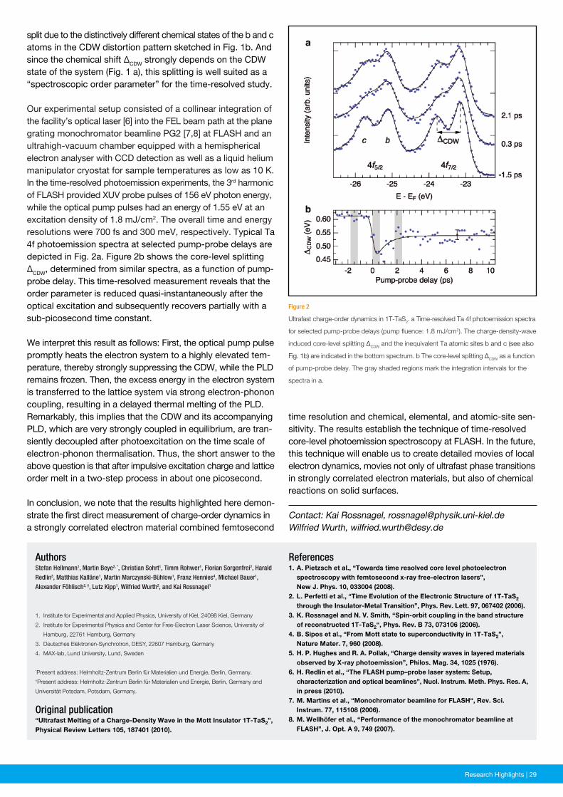
Figure 2
Ultrafast charge-order dynamics in 1T-TaS2. a Time-resolved Ta 4f photoemission spectra
for selected pump-probe delays (pump fluence: 1.8 mJ/cm2). The charge-density-wave
induced core-level splitting ∆CDW and the inequivalent Ta atomic sites b and c (see also
Fig. 1b) are indicated in the bottom spectrum. b The core-level splitting ∆CDW as a function
of pump-probe delay. The gray shaded regions mark the integration intervals for the
spectra in a.
References1. A. Pietzsch et al., “Towards time resolved core level photoelectron spectroscopy with femtosecond x-ray free-electron lasers”, New J. Phys. 10, 033004 (2008).2. L. Perfetti et al., “Time Evolution of the Electronic Structure of 1T-TaS2 through the Insulator-Metal Transition”, Phys. Rev. Lett. 97, 067402 (2006).3. K. Rossnagel and N. V. Smith, “Spin-orbit coupling in the band structure of reconstructed 1T-TaS2“, Phys. Rev. B 73, 073106 (2006).4. B. Sipos et al., “From Mott state to superconductivity in 1T-TaS2”, Nature Mater. 7, 960 (2008).5. H. P. Hughes and R. A. Pollak, “Charge density waves in layered materials observed by X-ray photoemission”, Philos. Mag. 34, 1025 (1976).6. H. Redlin et al., “The FLASH pump–probe laser system: Setup, characterization and optical beamlines”, Nucl. Instrum. Meth. Phys. Res. A, in press (2010). 7. M. Martins et al., “Monochromator beamline for FLASH“, Rev. Sci. Instrum. 77, 115108 (2006).8. M. Wellhöfer et al., “Performance of the monochromator beamline at FLASH”, J. Opt. A 9, 749 (2007).
AuthorsStefan Hellmann1, Martin Beye2, *, Christian Sohrt1, Timm Rohwer1, Florian Sorgenfrei2, Harald Redlin3, Matthias Kalläne1, Martin Marczynski-Bühlow1, Franz Hennies4, Michael Bauer1, Alexander Föhlisch2, †, Lutz Kipp1, Wilfried Wurth2, and Kai Rossnagel1
1. Institute for Experimental and Applied Physics, University of Kiel, 24098 Kiel, Germany
2. Institute for Experimental Physics and Center for Free-Electron Laser Science, University of
Hamburg, 22761 Hamburg, Germany
3. Deutsches Elektronen-Synchrotron, DESY, 22607 Hamburg, Germany
4. MAX-lab, Lund University, Lund, Sweden
*Present address: Helmholtz-Zentrum Berlin für Materialien und Energie, Berlin, Germany.†Present address: Helmholtz-Zentrum Berlin für Materialien und Energie, Berlin, Germany and
Universität Potsdam, Potsdam, Germany.
Original publication“Ultrafast Melting of a Charge-Density Wave in the Mott Insulator 1T-TaS2”,Physical Review Letters 105, 187401 (2010).
split due to the distinctively different chemical states of the b and c atoms in the CDW distortion pattern sketched in Fig. 1b. And since the chemical shift ∆CDW strongly depends on the CDW state of the system (Fig. 1 a), this splitting is well suited as a “spectroscopic order parameter” for the time-resolved study.
Our experimental setup consisted of a collinear integration of the facility’s optical laser [6] into the FEL beam path at the plane grating monochromator beamline PG2 [7,8] at FLASH and an ultrahigh-vacuum chamber equipped with a hemispherical electron analyser with CCD detection as well as a liquid helium manipulator cryostat for sample temperatures as low as 10 K. In the time-resolved photoemission experiments, the 3rd harmonic of FLASH provided XUV probe pulses of 156 eV photon energy, while the optical pump pulses had an energy of 1.55 eV at an excitation density of 1.8 mJ/cm2. The overall time and energy resolutions were 700 fs and 300 meV, respectively. Typical Ta 4f photoemission spectra at selected pump-probe delays are depicted in Fig. 2a. Figure 2b shows the core-level splitting ∆CDW, determined from similar spectra, as a function of pump-probe delay. This time-resolved measurement reveals that the order parameter is reduced quasi-instantaneously after the optical excitation and subsequently recovers partially with a sub-picosecond time constant.
We interpret this result as follows: First, the optical pump pulse promptly heats the electron system to a highly elevated tem-perature, thereby strongly suppressing the CDW, while the PLD remains frozen. Then, the excess energy in the electron system is transferred to the lattice system via strong electron-phonon coupling, resulting in a delayed thermal melting of the PLD. Remarkably, this implies that the CDW and its accompanying PLD, which are very strongly coupled in equilibrium, are tran-siently decoupled after photoexcitation on the time scale of electron-phonon thermalisation. Thus, the short answer to the above question is that after impulsive excitation charge and lattice order melt in a two-step process in about one picosecond.
In conclusion, we note that the results highlighted here demon-strate the first direct measurement of charge-order dynamics in a strongly correlated electron material combined femtosecond
Contact: Kai Rossnagel, [email protected] Wurth, [email protected]
time resolution and chemical, elemental, and atomic-site sen-sitivity. The results establish the technique of time-resolved core-level photoemission spectroscopy at FLASH. In the future, this technique will enable us to create detailed movies of local electron dynamics, movies not only of ultrafast phase transitions in strongly correlated electron materials, but also of chemical reactions on solid surfaces.
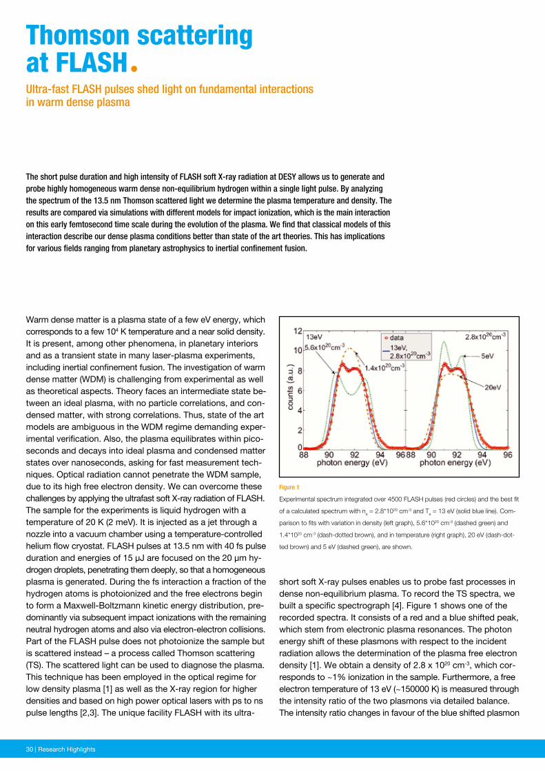
30 | News and Events30 | Research Highlights
short soft X-ray pulses enables us to probe fast processes in dense non-equilibrium plasma. To record the TS spectra, we built a specific spectrograph [4]. Figure 1 shows one of the recorded spectra. It consists of a red and a blue shifted peak, which stem from electronic plasma resonances. The photon energy shift of these plasmons with respect to the incident radiation allows the determination of the plasma free electron density [1]. We obtain a density of 2.8 x 1020 cm-3, which cor-responds to ~1% ionization in the sample. Furthermore, a free electron temperature of 13 eV (~150000 K) is measured through the intensity ratio of the two plasmons via detailed balance. The intensity ratio changes in favour of the blue shifted plasmon
Figure 1
Experimental spectrum integrated over 4500 FLASH pulses (red circles) and the best fit
of a calculated spectrum with ne = 2.8*1020 cm-3 and Te = 13 eV (solid blue line). Com-
parison to fits with variation in density (left graph), 5.6*1020 cm-3 (dashed green) and
1.4*1020 cm-3 (dash-dotted brown), and in temperature (right graph), 20 eV (dash-dot-
ted brown) and 5 eV (dashed green), are shown.
The short pulse duration and high intensity of FLASH soft X-ray radiation at DESY allows us to generate and probe highly homogeneous warm dense non-equilibrium hydrogen within a single light pulse. By analyzing the spectrum of the 13.5 nm Thomson scattered light we determine the plasma temperature and density. The results are compared via simulations with different models for impact ionization, which is the main interaction on this early femtosecond time scale during the evolution of the plasma. We find that classical models of this interaction describe our dense plasma conditions better than state of the art theories. This has implications for various fields ranging from planetary astrophysics to inertial confinement fusion.
Warm dense matter is a plasma state of a few eV energy, which corresponds to a few 104 K temperature and a near solid density. It is present, among other phenomena, in planetary interiors and as a transient state in many laser-plasma experiments, including inertial confinement fusion. The investigation of warm dense matter (WDM) is challenging from experimental as well as theoretical aspects. Theory faces an intermediate state be-tween an ideal plasma, with no particle correlations, and con-densed matter, with strong correlations. Thus, state of the art models are ambiguous in the WDM regime demanding exper-imental verification. Also, the plasma equilibrates within pico-seconds and decays into ideal plasma and condensed matter states over nanoseconds, asking for fast measurement tech-niques. Optical radiation cannot penetrate the WDM sample, due to its high free electron density. We can overcome these challenges by applying the ultrafast soft X-ray radiation of FLASH.The sample for the experiments is liquid hydrogen with a temperature of 20 K (2 meV). It is injected as a jet through a nozzle into a vacuum chamber using a temperature-controlled helium flow cryostat. FLASH pulses at 13.5 nm with 40 fs pulse duration and energies of 15 µJ are focused on the 20 µm hy-drogen droplets, penetrating them deeply, so that a homogeneous plasma is generated. During the fs interaction a fraction of the hydrogen atoms is photoionized and the free electrons begin to form a Maxwell-Boltzmann kinetic energy distribution, pre-dominantly via subsequent impact ionizations with the remaining neutral hydrogen atoms and also via electron-electron collisions.Part of the FLASH pulse does not photoionize the sample but is scattered instead – a process called Thomson scattering (TS). The scattered light can be used to diagnose the plasma. This technique has been employed in the optical regime for low density plasma [1] as well as the X-ray region for higher densities and based on high power optical lasers with ps to ns pulse lengths [2,3]. The unique facility FLASH with its ultra-
thomson scattering at FLAshªUltra-fast FLASH pulses shed light on fundamental interactions in warm dense plasma
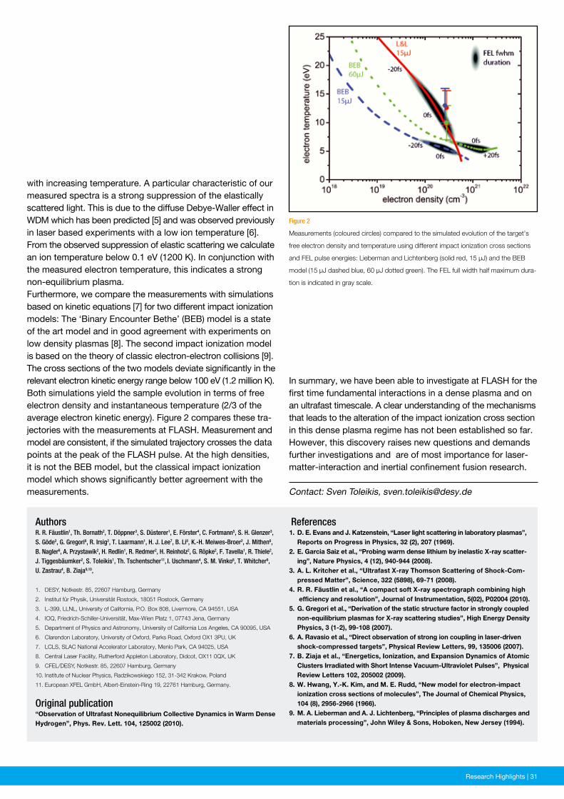
News and Events | 31Research Highlights | 31
Figure 2
Measurements (coloured circles) compared to the simulated evolution of the target’s
free electron density and temperature using different impact ionization cross sections
and FEL pulse energies: Lieberman and Lichtenberg (solid red, 15 µJ) and the BEB
model (15 µJ dashed blue, 60 µJ dotted green). The FEL full width half maximum dura-
tion is indicated in gray scale.
References1. D. E. Evans and J. Katzenstein, “Laser light scattering in laboratory plasmas”, Reports on Progress in Physics, 32 (2), 207 (1969).2. E. Garcia Saiz et al., “Probing warm dense lithium by inelastic X-ray scatter- ing”, Nature Physics, 4 (12), 940-944 (2008).3. A. L. Kritcher et al., “Ultrafast X-ray Thomson Scattering of Shock-Com- pressed Matter”, Science, 322 (5898), 69-71 (2008).4. R. R. Fäustlin et al., “A compact soft X-ray spectrograph combining high efficiency and resolution”, Journal of Instrumentation, 5(02), P02004 (2010).5. G. Gregori et al., “Derivation of the static structure factor in strongly coupled non-equilibrium plasmas for X-ray scattering studies”, High Energy Density Physics, 3 (1-2), 99-108 (2007).6. A. Ravasio et al., “Direct observation of strong ion coupling in laser-driven shock-compressed targets”, Physical Review Letters, 99, 135006 (2007).7. B. Ziaja et al., “Energetics, Ionization, and Expansion Dynamics of Atomic Clusters Irradiated with Short Intense Vacuum-Ultraviolet Pulses”, Physical Review Letters 102, 205002 (2009).8. W. Hwang, Y.-K. Kim, and M. E. Rudd, “New model for electron-impact ionization cross sections of molecules”, The Journal of Chemical Physics, 104 (8), 2956-2966 (1966).9. M. A. Lieberman and A. J. Lichtenberg, “Principles of plasma discharges and materials processing”, John Wiley & Sons, Hoboken, New Jersey (1994).
AuthorsR. R. Fäustlin1, Th. Bornath2, T. Döppner3, S. Düsterer1, E. Förster4, C. Fortmann5, S. H. Glenzer3, S. Göde2, G. Gregori6, R. Irsig2, T. Laarmann1, H. J. Lee7, B. Li8, K.-H. Meiwes-Broer2, J. Mithen6, B. Nagler6, A. Przystawik2, H. Redlin1, R. Redmer2, H. Reinholz2, G. Röpke2, F. Tavella1, R. Thiele2, J. Tiggesbäumker2, S. Toleikis1, Th. Tschentscher11, I. Uschmann4, S. M. Vinko6, T. Whitcher6, U. Zastrau4, B. Ziaja9,10,
1. DESY, Notkestr. 85, 22607 Hamburg, Germany
2. Institut für Physik, Universität Rostock, 18051 Rostock, Germany
3. L-399, LLNL, University of California, P.O. Box 808, Livermore, CA 94551, USA
4. IOQ, Friedrich-Schiller-Universität, Max-Wien Platz 1, 07743 Jena, Germany
5. Department of Physics and Astronomy, University of California Los Angeles, CA 90095, USA
6. Clarendon Laboratory, University of Oxford, Parks Road, Oxford OX1 3PU, UK
7. LCLS, SLAC National Accelerator Laboratory, Menlo Park, CA 94025, USA
8. Central Laser Facility, Rutherford Appleton Laboratory, Didcot, OX11 0QX, UK
9. CFEL/DESY, Notkestr. 85, 22607 Hamburg, Germany
10. Institute of Nuclear Physics, Radzikowskiego 152, 31-342 Krakow, Poland
11. European XFEL GmbH, Albert-Einstein-Ring 19, 22761 Hamburg, Germany.
Original publication“Observation of Ultrafast Nonequilibrium Collective Dynamics in Warm Dense Hydrogen”, Phys. Rev. Lett. 104, 125002 (2010).
with increasing temperature. A particular characteristic of our measured spectra is a strong suppression of the elastically scattered light. This is due to the diffuse Debye-Waller effect in WDM which has been predicted [5] and was observed previously in laser based experiments with a low ion temperature [6]. From the observed suppression of elastic scattering we calculate an ion temperature below 0.1 eV (1200 K). In conjunction with the measured electron temperature, this indicates a strong non-equilibrium plasma.Furthermore, we compare the measurements with simulations based on kinetic equations [7] for two different impact ionization models: The ‘Binary Encounter Bethe’ (BEB) model is a state of the art model and in good agreement with experiments on low density plasmas [8]. The second impact ionization model is based on the theory of classic electron-electron collisions [9]. The cross sections of the two models deviate significantly in the relevant electron kinetic energy range below 100 eV (1.2 million K). Both simulations yield the sample evolution in terms of free electron density and instantaneous temperature (2/3 of the average electron kinetic energy). Figure 2 compares these tra-jectories with the measurements at FLASH. Measurement and model are consistent, if the simulated trajectory crosses the data points at the peak of the FLASH pulse. At the high densities, it is not the BEB model, but the classical impact ionization model which shows significantly better agreement with the measurements. Contact: Sven Toleikis, [email protected]
In summary, we have been able to investigate at FLASH for the first time fundamental interactions in a dense plasma and on an ultrafast timescale. A clear understanding of the mechanisms that leads to the alteration of the impact ionization cross section in this dense plasma regime has not been established so far. However, this discovery raises new questions and demands further investigations and are of most importance for laser-matter-interaction and inertial confinement fusion research.
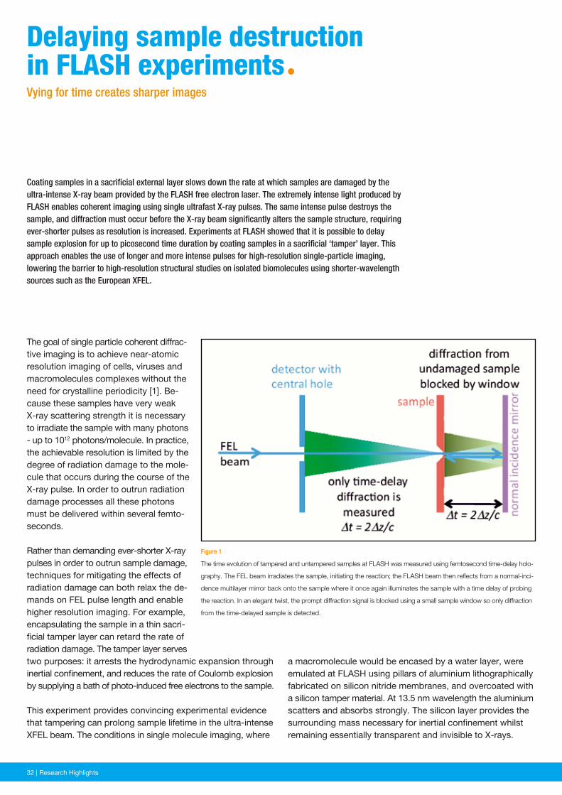
32 | News and Events32 | Research Highlights
a macromolecule would be encased by a water layer, were emulated at FLASH using pillars of aluminium lithographically fabricated on silicon nitride membranes, and overcoated with a silicon tamper material. At 13.5 nm wavelength the aluminium scatters and absorbs strongly. The silicon layer provides the surrounding mass necessary for inertial confinement whilst remaining essentially transparent and invisible to X-rays.
Figure 1
The time evolution of tampered and untampered samples at FLASH was measured using femtosecond time-delay holo-
graphy. The FEL beam irradiates the sample, initiating the reaction; the FLASH beam then reflects from a normal-inci-
dence multilayer mirror back onto the sample where it once again illuminates the sample with a time delay of probing
the reaction. In an elegant twist, the prompt diffraction signal is blocked using a small sample window so only diffraction
from the time-delayed sample is detected.
Coating samples in a sacrificial external layer slows down the rate at which samples are damaged by the ultra-intense X-ray beam provided by the FLASH free electron laser. The extremely intense light produced by FLASH enables coherent imaging using single ultrafast X-ray pulses. The same intense pulse destroys the sample, and diffraction must occur before the X-ray beam significantly alters the sample structure, requiring ever-shorter pulses as resolution is increased. Experiments at FLASH showed that it is possible to delay sample explosion for up to picosecond time duration by coating samples in a sacrificial ‘tamper’ layer. This approach enables the use of longer and more intense pulses for high-resolution single-particle imaging, lowering the barrier to high-resolution structural studies on isolated biomolecules using shorter-wavelength sources such as the European XFEL.
The goal of single particle coherent diffrac-tive imaging is to achieve near-atomic resolution imaging of cells, viruses and macromolecules complexes without the need for crystalline periodicity [1]. Be-cause these samples have very weak X-ray scattering strength it is necessary to irradiate the sample with many photons - up to 1012 photons/molecule. In practice, the achievable resolution is limited by the degree of radiation damage to the mole-cule that occurs during the course of the X-ray pulse. In order to outrun radiation damage processes all these photons must be delivered within several femto-seconds.
Rather than demanding ever-shorter X-ray pulses in order to outrun sample damage, techniques for mitigating the effects of radiation damage can both relax the de-mands on FEL pulse length and enable higher resolution imaging. For example, encapsulating the sample in a thin sacri-ficial tamper layer can retard the rate of radiation damage. The tamper layer serves two purposes: it arrests the hydrodynamic expansion through inertial confinement, and reduces the rate of Coulomb explosion by supplying a bath of photo-induced free electrons to the sample.
This experiment provides convincing experimental evidence that tampering can prolong sample lifetime in the ultra-intense XFEL beam. The conditions in single molecule imaging, where
Delaying sample destruction in FLAsh experimentsªVying for time creates sharper images
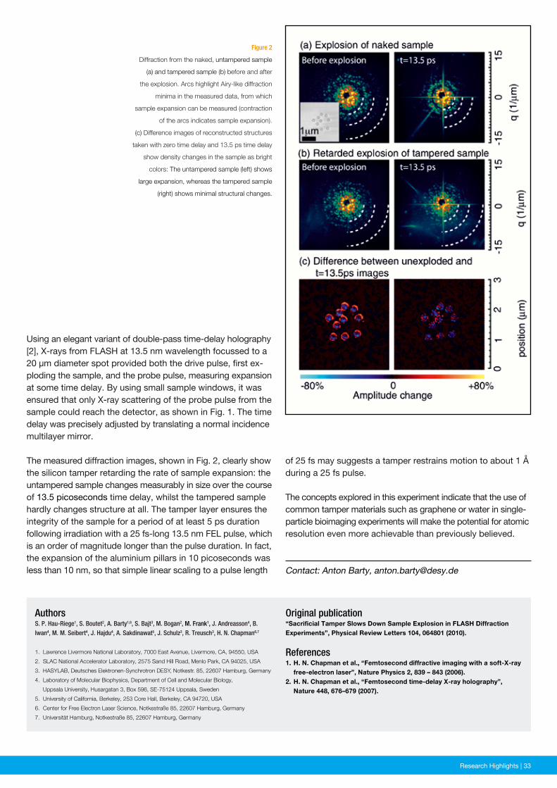
News and Events | 33Research Highlights | 33
Figure 2
Diffraction from the naked, untampered sample
(a) and tampered sample (b) before and after
the explosion. Arcs highlight Airy-like diffraction
minima in the measured data, from which
sample expansion can be measured (contraction
of the arcs indicates sample expansion).
(c) Difference images of reconstructed structures
taken with zero time delay and 13.5 ps time delay
show density changes in the sample as bright
colors: The untampered sample (left) shows
large expansion, whereas the tampered sample
(right) shows minimal structural changes.
Original publication“Sacrificial Tamper Slows Down Sample Explosion in FLASH Diffraction Experiments”, Physical Review Letters 104, 064801 (2010).
References1. H. N. Chapman et al., “Femtosecond diffractive imaging with a soft-X-ray free-electron laser”, Nature Physics 2, 839 – 843 (2006). 2. H. N. Chapman et al., “Femtosecond time-delay X-ray holography”, Nature 448, 676–679 (2007).
AuthorsS. P. Hau-Riege1, S. Boutet2, A. Barty1,6, S. Bajt3, M. Bogan2, M. Frank1, J. Andreasson4, B. Iwan4, M. M. Seibert4, J. Hajdu4, A. Sakdinawat5, J. Schulz3, R. Treusch3, H. N. Chapman6,7
1. Lawrence Livermore National Laboratory, 7000 East Avenue, Livermore, CA, 94550, USA
2. SLAC National Accelerator Laboratory, 2575 Sand Hill Road, Menlo Park, CA 94025, USA
3. HASYLAB, Deutsches Elektronen-Synchrotron DESY, Notkestr. 85, 22607 Hamburg, Germany
4. Laboratory of Molecular Biophysics, Department of Cell and Molecular Biology,
Uppsala University, Husargatan 3, Box 596, SE-75124 Uppsala, Sweden
5. University of California, Berkeley, 253 Core Hall, Berkeley, CA 94720, USA
6. Center for Free Electron Laser Science, Notkestraße 85, 22607 Hamburg, Germany
7. Universität Hamburg, Notkestraße 85, 22607 Hamburg, Germany
Using an elegant variant of double-pass time-delay holography [2], X-rays from FLASH at 13.5 nm wavelength focussed to a 20 µm diameter spot provided both the drive pulse, first ex-ploding the sample, and the probe pulse, measuring expansion at some time delay. By using small sample windows, it was ensured that only X-ray scattering of the probe pulse from the sample could reach the detector, as shown in Fig. 1. The time delay was precisely adjusted by translating a normal incidence multi layer mirror.
The measured diffraction images, shown in Fig. 2, clearly show the silicon tamper retarding the rate of sample expansion: the untampered sample changes measurably in size over the course of 13.5 picoseconds time delay, whilst the tampered sample hardly changes structure at all. The tamper layer ensures the integrity of the sample for a period of at least 5 ps duration following irradiation with a 25 fs-long 13.5 nm FEL pulse, which is an order of magnitude longer than the pulse duration. In fact, the expansion of the aluminium pillars in 10 picoseconds was less than 10 nm, so that simple linear scaling to a pulse length Contact: Anton Barty, [email protected]
of 25 fs may suggests a tamper restrains motion to about 1 Å during a 25 fs pulse.
The concepts explored in this experiment indicate that the use of common tamper materials such as graphene or water in single-particle bioimaging experiments will make the potential for atomic resolution even more achievable than previously believed.
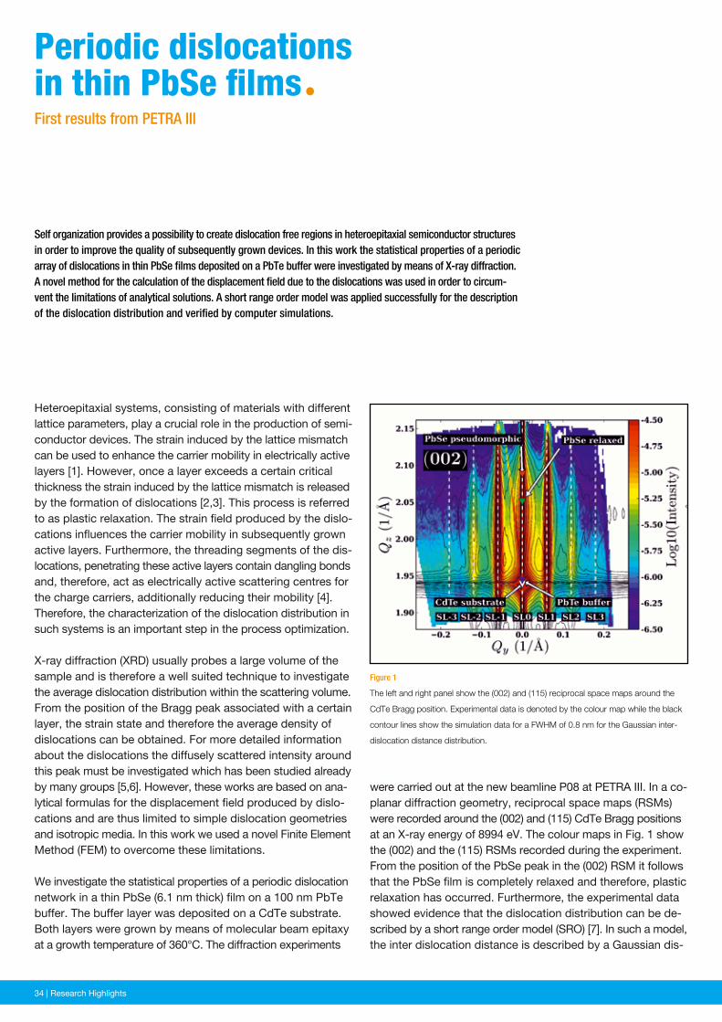
34 | News and Events34 | Research Highlights
were carried out at the new beamline P08 at PETRA III. In a co-planar diffraction geometry, reciprocal space maps (RSMs) were recorded around the (002) and (115) CdTe Bragg positions at an X-ray energy of 8994 eV. The colour maps in Fig. 1 show the (002) and the (115) RSMs recorded during the experiment. From the position of the PbSe peak in the (002) RSM it follows that the PbSe film is completely relaxed and therefore, plastic relaxation has occurred. Furthermore, the experimental data showed evidence that the dislocation distribution can be de-scribed by a short range order model (SRO) [7]. In such a model, the inter dislocation distance is described by a Gaussian dis-
Figure 1
The left and right panel show the (002) and (115) reciprocal space maps around the
CdTe Bragg position. Experimental data is denoted by the colour map while the black
contour lines show the simulation data for a FWHM of 0.8 nm for the Gaussian inter-
dislocation distance distribution.
Self organization provides a possibility to create dislocation free regions in heteroepitaxial semiconductor struc tures in order to improve the quality of subsequently grown devices. In this work the statistical properties of a periodic array of dislocations in thin PbSe films deposited on a PbTe buffer were investigated by means of X-ray diffraction. A novel method for the calculation of the displacement field due to the dislocations was used in order to circum-vent the limitations of analytical solutions. A short range order model was applied successfully for the description of the dislocation distribution and verified by computer simulations.
Heteroepitaxial systems, consisting of materials with different lattice parameters, play a crucial role in the production of semi-conductor devices. The strain induced by the lattice mismatch can be used to enhance the carrier mobility in electrically active layers [1]. However, once a layer exceeds a certain critical thickness the strain induced by the lattice mismatch is released by the formation of dislocations [2,3]. This process is referred to as plastic relaxation. The strain field produced by the dislo-cations influences the carrier mobility in subsequently grown active layers. Furthermore, the threading segments of the dis-locations, penetrating these active layers contain dangling bonds and, therefore, act as electrically active scattering centres for the charge carriers, additionally reducing their mobility [4]. Therefore, the characterization of the dislocation distribution in such systems is an important step in the process optimization.
X-ray diffraction (XRD) usually probes a large volume of the sample and is therefore a well suited technique to investigate the average dislocation distribution within the scattering volume. From the position of the Bragg peak associated with a certain layer, the strain state and therefore the average density of dislocations can be obtained. For more detailed information about the dislocations the diffusely scattered intensity around this peak must be investigated which has been studied already by many groups [5,6]. However, these works are based on ana-lytical formulas for the displacement field produced by dislo-cations and are thus limited to simple dislocation geo metries and isotropic media. In this work we used a novel Finite Element Method (FEM) to overcome these limitations.
We investigate the statistical properties of a periodic dislocation network in a thin PbSe (6.1 nm thick) film on a 100 nm PbTe buffer. The buffer layer was deposited on a CdTe substrate. Both layers were grown by means of molecular beam epitaxy at a growth temperature of 360°C. The diffraction experiments
periodic dislocations in thin PbSe filmsªFirst results from PETRA III
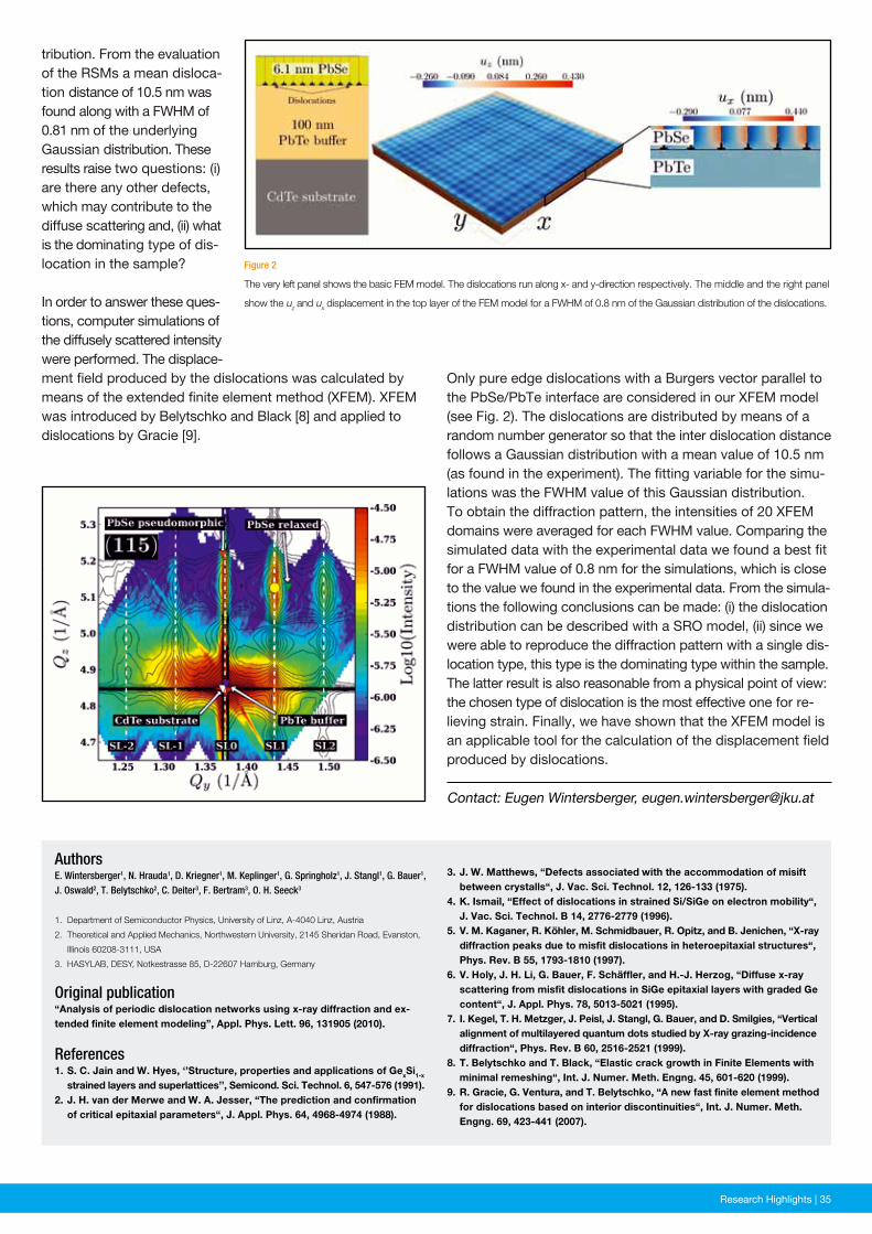
News and Events | 35Research Highlights | 35
Figure 2
The very left panel shows the basic FEM model. The dislocations run along x- and y-direction respectively. The middle and the right panel
show the uz and ux displacement in the top layer of the FEM model for a FWHM of 0.8 nm of the Gaussian distribution of the dislocations.
3. J. W. Matthews, “Defects associated with the accommodation of misift between crystalls“, J. Vac. Sci. Technol. 12, 126-133 (1975).4. K. Ismail, “Effect of dislocations in strained Si/SiGe on electron mobility“, J. Vac. Sci. Technol. B 14, 2776-2779 (1996).5. V. M. Kaganer, R. Köhler, M. Schmidbauer, R. Opitz, and B. Jenichen, “X-ray diffraction peaks due to misfit dislocations in heteroepitaxial structures“, Phys. Rev. B 55, 1793-1810 (1997).6. V. Holy, J. H. Li, G. Bauer, F. Schäffler, and H.-J. Herzog, “Diffuse x-ray scattering from misfit dislocations in SiGe epitaxial layers with graded Ge content“, J. Appl. Phys. 78, 5013-5021 (1995).7. I. Kegel, T. H. Metzger, J. Peisl, J. Stangl, G. Bauer, and D. Smilgies, “Vertical alignment of multilayered quantum dots studied by X-ray grazing-incidence diffraction“, Phys. Rev. B 60, 2516-2521 (1999).8. T. Belytschko and T. Black, “Elastic crack growth in Finite Elements with minimal remeshing“, Int. J. Numer. Meth. Engng. 45, 601-620 (1999).9. R. Gracie, G. Ventura, and T. Belytschko, “A new fast finite element method for dislocations based on interior discontinuities“, Int. J. Numer. Meth. Engng. 69, 423-441 (2007).
AuthorsE. Wintersberger1, N. Hrauda1, D. Kriegner1, M. Keplinger1, G. Springholz1, J. Stangl1, G. Bauer1, J. Oswald2, T. Belytschko2, C. Deiter3, F. Bertram3, O. H. Seeck3
1. Department of Semiconductor Physics, University of Linz, A-4040 Linz, Austria
2. Theoretical and Applied Mechanics, Northwestern University, 2145 Sheridan Road, Evanston,
Illinois 60208-3111, USA
3. HASYLAB, DESY, Notkestrasse 85, D-22607 Hamburg, Germany
Original publication“Analysis of periodic dislocation networks using x-ray diffraction and ex-tended finite element modeling”, Appl. Phys. Lett. 96, 131905 (2010).
References1. S. C. Jain and W. Hyes, ‘’Structure, properties and applications of GexSi1-x strained layers and superlattices’’, Semicond. Sci. Technol. 6, 547-576 (1991).2. J. H. van der Merwe and W. A. Jesser, “The prediction and confirmation of critical epitaxial parameters“, J. Appl. Phys. 64, 4968-4974 (1988).
tribution. From the evaluation of the RSMs a mean disloca-tion distance of 10.5 nm was found along with a FWHM of 0.81 nm of the underlying Gaussian distribution. These results raise two questions: (i) are there any other defects, which may contribute to the diffuse scattering and, (ii) what is the dominating type of dis-location in the sample?
In order to answer these ques-tions, computer simulations of the diffusely scattered intensity were performed. The displace-ment field produced by the dislocations was calculated by means of the extended finite element method (XFEM). XFEM was introduced by Belytschko and Black [8] and applied to dislocations by Gracie [9].
Contact: Eugen Wintersberger, [email protected]
Only pure edge dislocations with a Burgers vector parallel to the PbSe/PbTe interface are considered in our XFEM model (see Fig. 2). The dislocations are distributed by means of a random number generator so that the inter dislocation distance follows a Gaussian distribution with a mean value of 10.5 nm (as found in the experiment). The fitting variable for the simu-lations was the FWHM value of this Gaussian distribution. To obtain the diffraction pattern, the intensities of 20 XFEM domains were averaged for each FWHM value. Comparing the simulated data with the experimental data we found a best fit for a FWHM value of 0.8 nm for the simulations, which is close to the value we found in the experimental data. From the simula-tions the following conclusions can be made: (i) the dislocation distribution can be described with a SRO model, (ii) since we were able to reproduce the diffraction pattern with a single dis-location type, this type is the dominating type within the sample. The latter result is also reasonable from a physical point of view: the chosen type of dislocation is the most effective one for re-lieving strain. Finally, we have shown that the XFEM model is an applicable tool for the calculation of the displacement field produced by dislocations.
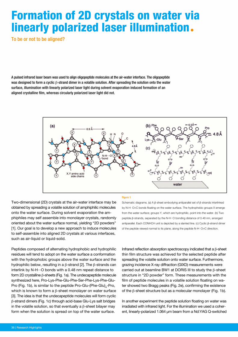
36 | News and Events36 | Research Highlights
Infrared reflection absorption spectroscopy indicated that a β-sheet thin film structure was achieved for the selected peptide after spreading the volatile solution onto water surface. Furthermore, grazing incidence X-ray diffraction (GIXD) measurements were carried out at beamline BW1 at DORIS III to study the β-sheet structure in “2D powder” form. These measurements with the film of peptide molecules in a volatile solution floating on wa-ter showed two Bragg peaks (Fig. 2e), confirming the existence of the β-sheet structure but as a molecular mono layer (Fig. 1b).
In another experiment the peptide solution floating on water was irradiated with infrared light. For the illumination we used a coher-ent, linearly-polarized 1.064 μm beam from a Nd:YAG Q-switched
Figure 1
Schematic diagrams. (a) A β-sheet embodying antiparallel set of β-strands interlinked
by N-H…O=C bonds floating on the water surface. The hydrophobic groups X emerge
from the water surface; groups Y, which are hydrophilic, point into the water. (b) Two
peptide β-strands, separated by the N-H…O bonding distance of 0.48 nm, arranged
antiparallel. Each CONHCH unit is depicted by a slanted line. (c) Cyclic β-strand dimer
of the peptide viewed normal to its plane, along the peptide N-H…O=C direction.
A pulsed infrared laser beam was used to align oligopeptide molecules at the air-water interface. The oligopeptide was designed to form a cyclic β-strand dimer in a volatile solution. After spreading the solution onto the water surface, illumination with linearly polarized laser light during solvent evaporation induced formation of an aligned crystalline film, whereas circularly polarized laser light did not.
Two-dimensional (2D) crystals at the air-water interface may be obtained by spreading a volatile solution of amphiphilic molecules onto the water surface. During solvent evaporation the am-phiphiles may self assemble into monolayer crystals, randomly oriented about the water surface normal, yielding “2D powders” [1]. Our goal is to develop a new approach to induce molecules to self-assemble into aligned 2D crystals at various interfaces, such as air-liquid or liquid-solid.
Peptides composed of alternating hydrophobic and hydrophilic residues will tend to adopt on the water surface a conformation with the hydrophobic groups above the water surface and the hydrophilic below, resulting in a β-strand [2]. The β-strands can interlink by N-H···O bonds with a 0.48 nm repeat distance to form 2D crystalline β-sheets (Fig. 1a). The undecapeptide molecule synthesized here, Pro-Lys-Phe-Glu-Phe-Ser-Phe-Lys-Phe-Glu-Pro (Fig. 1b), is similar to the peptide Pro-Glu-(Phe-Glu)4-Pro, which is known to form a β-sheet monolayer on water surface [3]. The idea is that the undecapeptide molecules will form cyclic β-strand dimers (Fig. 1c) through acid-base Glu-Lys salt bridges in the volatile solution, so that eventually a β-sheet bilayer may form when the solution is spread on top of the water surface.
Formation of 2D crystals on water vialinearly polarized laser illuminationªTo be or not to be aligned?
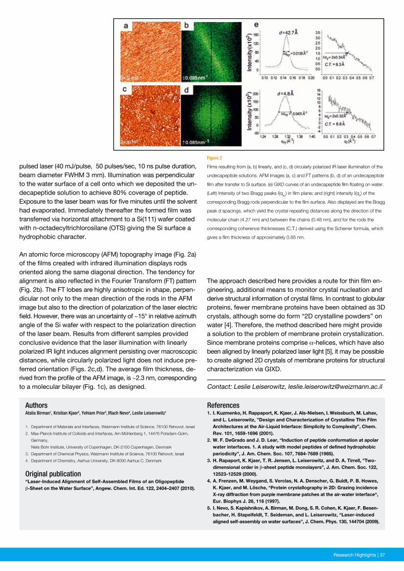
News and Events | 37Research Highlights | 37
Figure 2
Films resulting from (a, b) linearly, and (c, d) circularly polarized IR laser illumination of the
undecapeptide solutions. AFM images (a, c) and FT patterns (b, d) of an undecapeptide
film after transfer to Si surface. (e) GIXD curves of an undecapeptide film floating on water.
(Left) Intensity of two Bragg peaks I(qxy) in film plane; and (right) intensity I(qz) of the
corresponding Bragg rods perpendicular to the film surface. Also displayed are the Bragg
peak d spacings, which yield the crystal repeating distances along the direction of the
molecular chain (4.27 nm) and between the chains (0.48 nm), and for the rods the
corresponding coherence thicknesses (C.T.) derived using the Scherrer formula, which
gives a film thickness of approximately 0.85 nm.
References1. I. Kuzmenko, H. Rappaport, K. Kjaer, J. Als-Nielsen, I. Weissbuch, M. Lahav, and L. Leiserowitz, ”Design and Characterization of Crystalline Thin Film Architectures at the Air-Liquid Interface: Simplicity to Complexity”, Chem. Rev. 101, 1659-1696 (2001).2. W. F. DeGrado and J. D. Lear, “Induction of peptide conformation at apolar water interfaces. 1. A study with model peptides of defined hydrophobic periodicity”, J. Am. Chem. Soc. 107, 7684-7689 (1985).3. H. Rapaport, K. Kjaer, T. R. Jensen, L. Leiserowitz, and D. A. Tirrell, ”Two- dimensional order in β-sheet peptide monolayers”, J. Am. Chem. Soc. 122, 12523-12529 (2000).4. A. Frenzen, M. Weygand, S. Verclas, N. A. Denscher, G. Buldt, P. B. Howes, K. Kjaer, and M. Lösche, “Protein crystallography in 2D: Grazing incidence X-ray diffraction from purple membrane patches at the air-water interface“, Eur. Biophys J. 26, 116 (1997).5. I. Nevo, S. Kapishnikov, A. Birman, M. Dong, S. R. Cohen, K. Kjaer, F. Besen- bacher, H. Stapelfeldt, T. Seideman, and L. Leiserowitz, “Laser-induced aligned self-assembly on water surfaces”, J. Chem. Phys. 130, 144704 (2009).
AuthorsAtalia Birman1, Kristian Kjaer2, Yehiam Prior3, Iftach Nevo4, Leslie Leiserowitz1
1. Department of Materials and Interfaces, Weizmann Institute of Science, 76100 Rehovot, Israel
2. Max-Planck Institute of Colloids and Interfaces, Am Mühlenberg 1, 14476 Potsdam-Golm,
Germany,
Niels Bohr Institute, University of Copenhagen, DK-2100 Copenhagen, Denmark
3. Department of Chemical Physics, Weizmann Institute of Science, 76100 Rehovot, Israel
4. Department of Chemistry, Aarhus University, DK-8000 Aarhus C, Denmark
Original publication“Laser-Induced Alignment of Self-Assembled Films of an Oligopeptide
β-Sheet on the Water Surface”, Angew. Chem. Int. Ed. 122, 2404–2407 (2010).
pulsed laser (40 mJ/pulse, 50 pulses/sec, 10 ns pulse duration, beam diameter FWHM 3 mm). Illumination was perpendicular to the water surface of a cell onto which we deposited the un-decapeptide solution to achieve 80% coverage of peptide. Exposure to the laser beam was for five minutes until the solvent had evaporated. Immediately thereafter the formed film was transferred via horizontal attachment to a Si(111) wafer coated with n-octadecyltrichlorosilane (OTS) giving the Si surface a hydro phobic character.
An atomic force microscopy (AFM) topography image (Fig. 2a) of the films created with infrared illumination displays rods oriented along the same diagonal direction. The tendency for alignment is also reflected in the Fourier Transform (FT) pattern (Fig. 2b). The FT lobes are highly anisotropic in shape, perpen-dicular not only to the mean direction of the rods in the AFM image but also to the direction of polarization of the laser electric field. However, there was an uncertainty of ~15° in relative azimuth angle of the Si wafer with respect to the polarization direction of the laser beam. Results from different samples provided conclusive evidence that the laser illumination with linearly polarized IR light induces alignment persisting over macroscopic distances, while circularly polarized light does not induce pre-ferred orientation (Figs. 2c,d). The average film thickness, de-rived from the profile of the AFM image, is ~2.3 nm, corresponding to a molecular bilayer (Fig. 1c), as designed. Contact: Leslie Leiserowitz, [email protected]
The approach described here provides a route for thin film en-gineering, additional means to monitor crystal nucleation and derive structural information of crystal films. In contrast to globular proteins, fewer membrane proteins have been obtained as 3D crystals, although some do form “2D crystalline powders” on water [4]. Therefore, the method described here might provide a solution to the problem of membrane protein crystallization. Since membrane proteins comprise α-helices, which have also been aligned by linearly polarized laser light [5], it may be possible to create aligned 2D crystals of membrane proteins for structural characterization via GIXD.
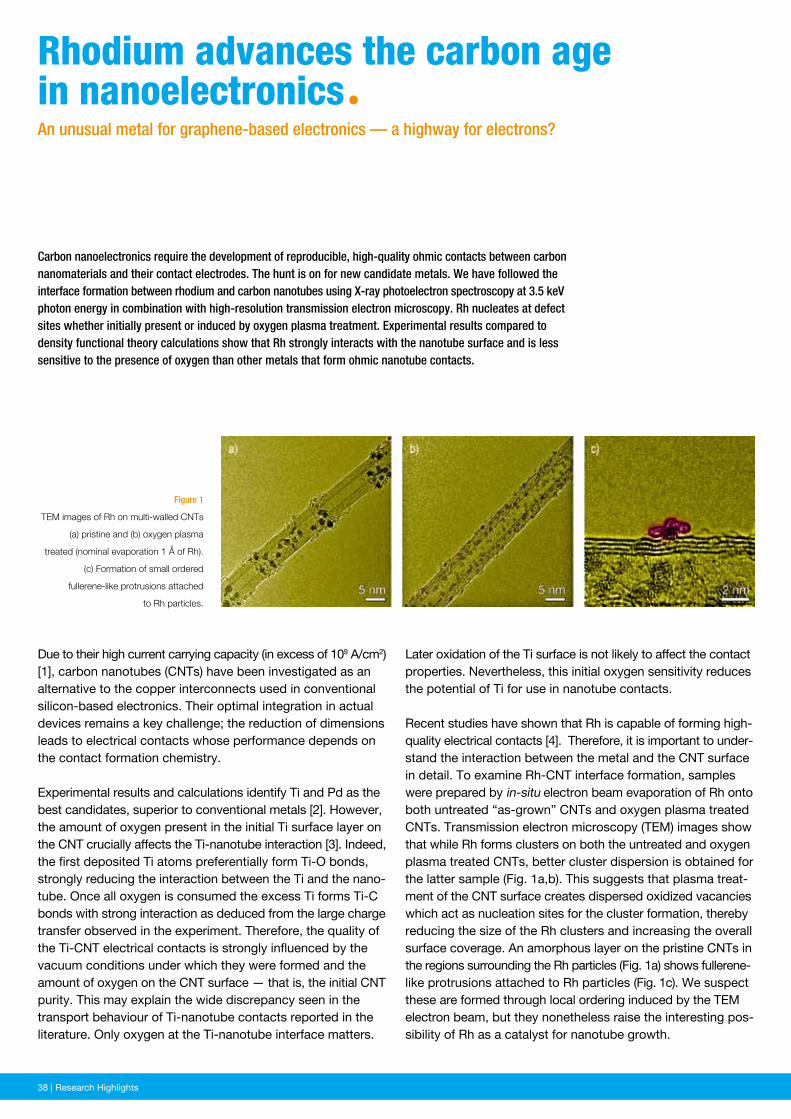
38 | News and Events38 | Research Highlights
Later oxidation of the Ti surface is not likely to affect the contact properties. Nevertheless, this initial oxygen sensitivity reduces the potential of Ti for use in nanotube contacts.
Recent studies have shown that Rh is capable of forming high-quality electrical contacts [4]. Therefore, it is important to under-stand the interaction between the metal and the CNT surface in detail. To examine Rh-CNT interface formation, samples were prepared by in-situ electron beam evaporation of Rh onto both untreated “as-grown” CNTs and oxygen plasma treated CNTs. Transmission electron microscopy (TEM) images show that while Rh forms clusters on both the untreated and oxygen plasma treated CNTs, better cluster dispersion is obtained for the latter sample (Fig. 1a,b). This suggests that plasma treat-ment of the CNT surface creates dispersed oxidized vacancies which act as nucleation sites for the cluster formation, thereby reducing the size of the Rh clusters and increasing the overall surface coverage. An amorphous layer on the pristine CNTs in the regions surrounding the Rh particles (Fig. 1a) shows fullerene-like protrusions attached to Rh particles (Fig. 1c). We suspect these are formed through local ordering induced by the TEM electron beam, but they nonetheless raise the interesting pos-sibility of Rh as a catalyst for nanotube growth.
Figure 1
TEM images of Rh on multi-walled CNTs
(a) pristine and (b) oxygen plasma
treated (nominal evaporation 1 Å of Rh).
(c) Formation of small ordered
fullerene-like protrusions attached
to Rh particles.
Carbon nanoelectronics require the development of reproducible, high-quality ohmic contacts between carbon nanomaterials and their contact electrodes. The hunt is on for new candidate metals. We have followed the interface formation between rhodium and carbon nanotubes using X-ray photoelectron spectroscopy at 3.5 keV photon energy in combination with high-resolution transmission electron microscopy. Rh nucleates at defect sites whether initially present or induced by oxygen plasma treatment. Experimental results compared to density functional theory calculations show that Rh strongly interacts with the nanotube surface and is less sensitive to the presence of oxygen than other metals that form ohmic nanotube contacts.
Due to their high current carrying capacity (in excess of 109 A/cm2) [1], carbon nanotubes (CNTs) have been investigated as an alternative to the copper interconnects used in conventional silicon-based electronics. Their optimal integration in actual devices remains a key challenge; the reduction of dimensions leads to electrical contacts whose performance depends on the contact formation chemistry.
Experimental results and calculations identify Ti and Pd as the best candidates, superior to conventional metals [2]. However, the amount of oxygen present in the initial Ti surface layer on the CNT crucially affects the Ti-nanotube interaction [3]. Indeed, the first deposited Ti atoms preferentially form Ti-O bonds, strongly reducing the interaction between the Ti and the nano-tube. Once all oxygen is consumed the excess Ti forms Ti-C bonds with strong interaction as deduced from the large charge transfer observed in the experiment. Therefore, the quality of the Ti-CNT electrical contacts is strongly influenced by the vacuum conditions under which they were formed and the amount of oxygen on the CNT surface — that is, the initial CNT purity. This may explain the wide discrepancy seen in the transport behaviour of Ti-nanotube contacts reported in the literature. Only oxygen at the Ti-nanotube interface matters.
Rhodium advances the carbon age in nanoelectronicsªAn unusual metal for graphene-based electronics — a highway for electrons?
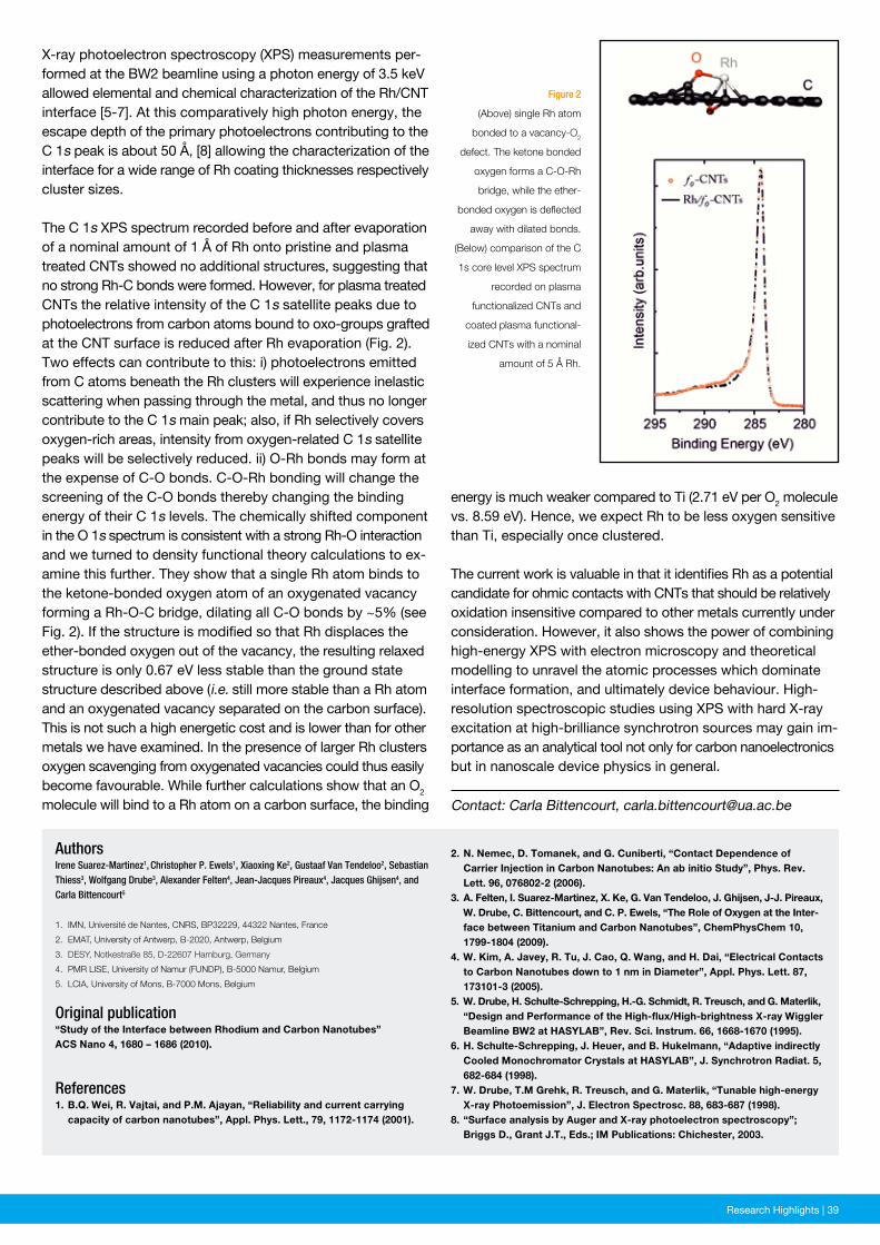
News and Events | 39Research Highlights | 39
Figure 2
(Above) single Rh atom
bonded to a vacancy-O2
defect. The ketone bonded
oxygen forms a C-O-Rh
bridge, while the ether-
bonded oxygen is deflected
away with dilated bonds.
(Below) comparison of the C
1s core level XPS spectrum
recorded on plasma
functionalized CNTs and
coated plasma functional -
ized CNTs with a nominal
amount of 5 Å Rh.
Contact: Carla Bittencourt, [email protected]
X-ray photoelectron spectroscopy (XPS) measurements per-formed at the BW2 beamline using a photon energy of 3.5 keV allowed elemental and chemical characterization of the Rh/CNT interface [5-7]. At this comparatively high photon energy, the escape depth of the primary photoelectrons contributing to the C 1s peak is about 50 Å, [8] allowing the characterization of the interface for a wide range of Rh coating thicknesses respectively cluster sizes.
The C 1s XPS spectrum recorded before and after evaporation of a nominal amount of 1 Å of Rh onto pristine and plasma treated CNTs showed no additional structures, suggesting that no strong Rh-C bonds were formed. However, for plasma treated CNTs the relative intensity of the C 1s satellite peaks due to photoelectrons from carbon atoms bound to oxo-groups grafted at the CNT surface is reduced after Rh evaporation (Fig. 2). Two effects can contribute to this: i) photoelectrons emitted from C atoms beneath the Rh clusters will experience inelastic scattering when passing through the metal, and thus no longer contribute to the C 1s main peak; also, if Rh selectively covers oxygen-rich areas, intensity from oxygen-related C 1s satellite peaks will be selectively reduced. ii) O-Rh bonds may form at the expense of C-O bonds. C-O-Rh bonding will change the screening of the C-O bonds thereby changing the binding energy of their C 1s levels. The chemically shifted component in the O 1s spectrum is consistent with a strong Rh-O interaction and we turned to density functional theory calculations to ex-amine this further. They show that a single Rh atom binds to the ketone-bonded oxygen atom of an oxygenated vacancy forming a Rh-O-C bridge, dilating all C-O bonds by ~5% (see Fig. 2). If the structure is modified so that Rh displaces the ether-bonded oxygen out of the vacancy, the resulting relaxed structure is only 0.67 eV less stable than the ground state structure described above (i.e. still more stable than a Rh atom and an oxygenated vacancy separated on the carbon surface). This is not such a high energetic cost and is lower than for other metals we have examined. In the presence of larger Rh clusters oxygen scavenging from oxygenated vacancies could thus easily become favourable. While further calculations show that an O2 molecule will bind to a Rh atom on a carbon surface, the binding
energy is much weaker compared to Ti (2.71 eV per O2 molecule vs. 8.59 eV). Hence, we expect Rh to be less oxygen sensitive than Ti, especially once clustered.
The current work is valuable in that it identifies Rh as a potential candidate for ohmic contacts with CNTs that should be relatively oxidation insensitive compared to other metals currently under consideration. However, it also shows the power of combining high-energy XPS with electron microscopy and theoretical modelling to unravel the atomic processes which dominate interface formation, and ultimately device behaviour. High-resolution spectroscopic studies using XPS with hard X-ray excitation at high-brilliance synchrotron sources may gain im-portance as an analytical tool not only for carbon nanoelectronics but in nanoscale device physics in general.
AuthorsIrene Suarez-Martinez1, Christopher P. Ewels1, Xiaoxing Ke2, Gustaaf Van Tendeloo2, Sebastian Thiess3, Wolfgang Drube3, Alexander Felten4, Jean-Jacques Pireaux4, Jacques Ghijsen4, and Carla Bittencourt5
1. IMN, Université de Nantes, CNRS, BP32229, 44322 Nantes, France
2. EMAT, University of Antwerp, B-2020, Antwerp, Belgium
3. DESY, Notkestraße 85, D-22607 Hamburg, Germany
4. PMR LISE, University of Namur (FUNDP), B-5000 Namur, Belgium
5. LCIA, University of Mons, B-7000 Mons, Belgium
Original publication“Study of the Interface between Rhodium and Carbon Nanotubes”ACS Nano 4, 1680 – 1686 (2010).
References1. B.Q. Wei, R. Vajtai, and P.M. Ajayan, “Reliability and current carrying capacity of carbon nanotubes”, Appl. Phys. Lett., 79, 1172-1174 (2001).
2. N. Nemec, D. Tomanek, and G. Cuniberti, “Contact Dependence of Carrier Injection in Carbon Nanotubes: An ab initio Study”, Phys. Rev. Lett. 96, 076802-2 (2006).3. A. Felten, I. Suarez-Martinez, X. Ke, G. Van Tendeloo, J. Ghijsen, J-J. Pireaux, W. Drube, C. Bittencourt, and C. P. Ewels, “The Role of Oxygen at the Inter - face between Titanium and Carbon Nanotubes”, ChemPhysChem 10, 1799-1804 (2009).4. W. Kim, A. Javey, R. Tu, J. Cao, Q. Wang, and H. Dai, “Electrical Contacts to Carbon Nanotubes down to 1 nm in Diameter”, Appl. Phys. Lett. 87, 173101-3 (2005).5. W. Drube, H. Schulte-Schrepping, H.-G. Schmidt, R. Treusch, and G. Materlik, “Design and Performance of the High-flux/High-brightness X-ray Wiggler Beamline BW2 at HASYLAB”, Rev. Sci. Instrum. 66, 1668-1670 (1995).6. H. Schulte-Schrepping, J. Heuer, and B. Hukelmann, “Adaptive indirectly Cooled Monochromator Crystals at HASYLAB”, J. Synchrotron Radiat. 5, 682-684 (1998).7. W. Drube, T.M Grehk, R. Treusch, and G. Materlik, “Tunable high-energy X-ray Photoemission”, J. Electron Spectrosc. 88, 683-687 (1998).8. “Surface analysis by Auger and X-ray photoelectron spectroscopy”; Briggs D., Grant J.T., Eds.; IM Publications: Chichester, 2003.
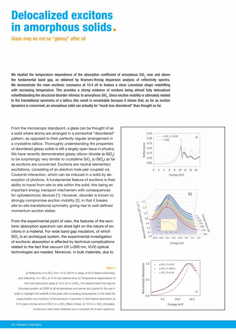
40 | News and Events40 | Research Highlights
Figure 1
a) Reflectivity of a-SiO2 from 10 to 300 K in steps of 50 K (black solid lines),
and reflectivity of c-SiO2 at 10 K (red dashed line); b) Temperature dependence of
the main absorption peak at 10.4 eV in a-SiO2: the dashed black line reports
the peak position at 300K at all temperatures and serves as a guide for the eye in
order to highlight the redshift of the peak with increasing temperature; in the inset the
peak position as a function of temperature is reported; c) Normalized absorption at
10 K (open circles) and at 300 K in a-SiO2 (filled circles), at 10 K in c-SiO2 (triangles).
Continuous lines were obtained via a Lorentzian fit of each spectrum.
We studied the temperature dependence of the absorption coefficient of amorphous SiO2 near and above the fundamental band gap, as obtained by Kramers-Kronig dispersion analysis of reflectivity spectra. We demonstrate the main excitonic resonance at 10.4 eV to feature a close Lorentzian shape redshifting with increasing temperature. This provides a strong evidence of excitons being almost fully delocalized notwithstanding the structural disorder intrinsic to amorphous SiO2. Since exciton mobility is ultimately related to the translational symmetry of a lattice, this result is remarkable because it shows that, as far as exciton dynamics is concerned, an amorphous solid can actually be “much less disordered” than thought so far.
From the microscopic standpoint, a glass can be thought of as a solid where atoms are arranged in a somewhat “disordered” pattern, as opposed to their perfectly regular arrangement in a crystalline lattice. Thoroughly understanding the properties of disordered glassy solids is still a largely open issue in physics. We have recently demonstrated glassy silicon dioxide (a-SiO2) to be surprisingly very similar to crystalline SiO2 (c-SiO2) as far as excitons are concerned. Excitons are neutral elementary excitations, consisting of an electron-hole pair coupled via Coulomb interaction, which can be induced in a solid by ab-sorption of photons. A fundamental feature of excitons is their ability to travel from site to site within the solid, this being an important energy transport mechanism with consequences for optoelectronic devices [1]. However, disorder is known to strongly compromise exciton mobility [2], in that it breaks site-to-site translational symmetry giving rise to well-defined momentum exciton states.
From the experimental point of view, the features of the exci-tonic absorption spectrum can shed light on the nature of ex-citons in a material. For wide band gap insulators, of which SiO2 is an archetypal system, the experimental investigation of excitonic absorption is affected by technical complications related to the fact that vacuum UV (<200 nm, VUV) optical technologies are needed. Moreover, in bulk materials, due to
Delocalized excitons in amorphous solidsªGlass may be not so “glassy” after all
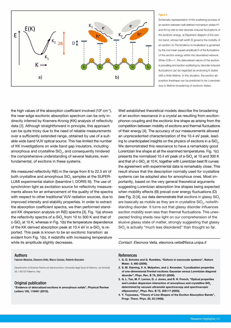
News and Events | 41Research Highlights | 41
Figure 2
Schematic representation of the scattering process of
an exciton between well-defined momentum states K1
and K2 by site-to-site disorder-induced fluctuations of
the excitonic energy. a) Dispersion diagram of the exci-
ton band, whose half-width B governs the mobility of
an exciton; b) The tendency to localization is governed
by the root mean square amplitude D of the fluctuations
of the exciton energy within the disordered network.
When D/B<<1, the delocalized nature of the exciton
is prevailing and exciton scattering by disorder-induced
fluctuations can be regarded as endowing K states
with a finite lifetime. In this situation, the exciton ab-
sorption lineshape can be predicted to be Lorentzian
due to lifetime broadening of excitonic states.
Contact: Eleonora Vella, [email protected]
the high values of the absorption coefficient involved (106 cm-1), the near-edge excitonic absorption spectrum can be only in-directly inferred by Kramers-Kronig (KK) analysis of reflectivity data [3]. Although straightforward in principle, this approach can be quite tricky due to the need of reliable measurements over a sufficiently extended range, obtained by use of a suit-able wide band VUV optical source. This has limited the number of KK investigations on wide band gap insulators, including amorphous and crystalline SiO2, and consequently hindered the comprehensive understanding of several features, even fundamental, of excitons in these systems.
We measured reflectivity R(E) in the range from 8 to 22.5 eV of both crystalline and amorphous SiO2 samples at the SUPER-LUMI experimental station (beamline I, DORIS III). The use of synchrotron light as excitation source for reflectivity measure-ments allows for an enhancement of the quality of the spectra with respect to other traditional VUV radiation sources, due to improved intensity and stability properties. In order to extract the absorption coefficient spectra, we then performed stand-ard KK dispersion analysis on R(E) spectra [3]. Fig. 1(a) shows the reflectivity spectra of a-SiO2 from 10 to 300 K and that of c-SiO2 at 10 K, whereas in Fig. 1(b) the temperature dependence of the KK derived absorption peak at 10.4 eV in a-SiO2 is re-ported. This peak is known to be an excitonic transition: as evident from Fig. 1(b), it redshifts with increasing temperature while its amplitude slightly decreases.
References1. G. D. Scholes and G. Rumbles, “Exitons in nanoscale systems”, Nature Mater. 5, 683 (2006).2. S. M. Vlaming, V. A. Malyshev, and J. Knoester, “Localization properties of one-dimensional Frenkel excitons: Gaussian versus Lorentzian diagonal disorder”, Phys. Rev. B 79, 205121 (2009).3. G. L. Tan, M. F. Lemon, D. J. Jones, and R. H. French, “Optical properties and London dispersion interaction of amorphous and crystalline SiO2 determined by vacuum ultraviolet spectroscopy and spectroscopic ellipsometry”, Phys. Rev. B 72, 205117 (2005).4. Y. Toyozawa, “Theory of Line-Shapes of the Exciton Absorption Bands”, Progr. Theor. Phys. 20, 53 (1958).
AuthorsFabrizio Messina, Eleonora Vella, Marco Cannas, Roberto Boscaino
Dipartimento di Scienze Fisiche ed Astronomiche, Università degli Studi di Palermo, via Archirafi
36, I-90123 Palermo, Italy
Original publication“Evidence of delocalized excitons in amorphous solids”, Physical Review Letters 105, 116401 (2010).
Well established theoretical models describe the broadening of an exciton resonance in a crystal as resulting from exciton-phonon coupling and the excitonic line shape as arising from the competition between mobility of excitons and thermal fluctuations of their energy [4]. The accuracy of our measurements allowed an unprecedented characterization of the 10.4 eV peak, lead-ing to unanticipated insights on the physics of excitons in a-SiO2. We demonstrated this resonance to have a remarkably good Lorentzian line shape at all the examined temperatures. Fig. 1(c) presents the normalized 10.4 eV peak of a-SiO2 at 10 and 300 K and that of c-SiO2 at 10 K, together with Lorentzian best fit curves: the agreement with experimental data is remarkably close. This result shows that the description normally used for crystalline systems can be adopted also for amorphous ones. Most im-portantly, based on the very general theoretical arguments suggesting Lorentzian absorption line shapes being expected when mobility effects (B) prevail over energy fluctuations (D) (see Fig. 2) [4], our data demonstrate that excitons in glassy SiO2 are basically as mobile as they are in crystalline SiO2, notwith-standing disorder. It turns out that glassy disorder influences exciton mobility even less than thermal fluctuations. This unex-pected finding sheds new light on our comprehension of the elusive glassy state of matter, strongly suggesting that glassy SiO2 is actually “much less disordered” than thought so far.
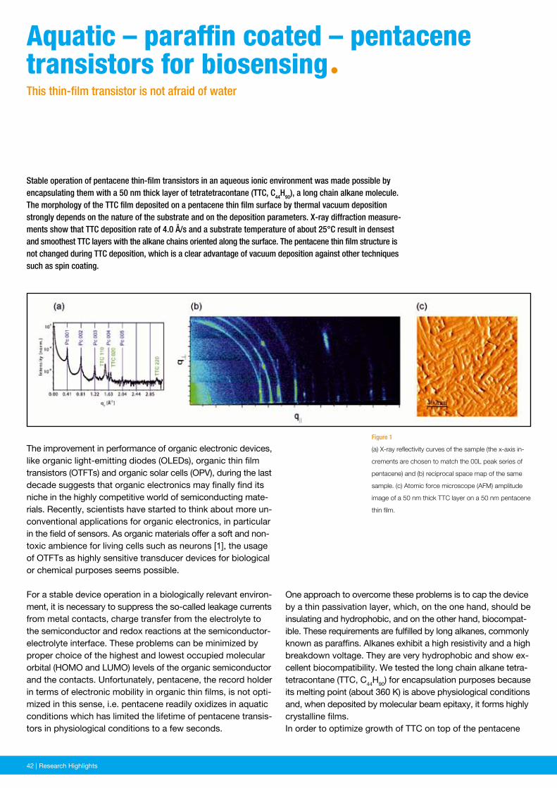
42 | News and Events42 | Research Highlights
One approach to overcome these problems is to cap the device by a thin passivation layer, which, on the one hand, should be insulating and hydrophobic, and on the other hand, biocompat-ible. These requirements are fulfilled by long alkanes, commonly known as paraffins. Alkanes exhibit a high resistivity and a high breakdown voltage. They are very hydrophobic and show ex-cellent biocompatibility. We tested the long chain alkane tetra-tetracontane (TTC, C44H90) for encapsulation purposes because its melting point (about 360 K) is above physiological conditions and, when deposited by molecular beam epitaxy, it forms highly crystalline films.In order to optimize growth of TTC on top of the pentacene
Figure 1
(a) X-ray reflectivity curves of the sample (the x-axis in-
crements are chosen to match the 00L peak series of
pentacene) and (b) reciprocal space map of the same
sample. (c) Atomic force microscope (AFM) amplitude
image of a 50 nm thick TTC layer on a 50 nm pentacene
thin film.
Stable operation of pentacene thin-film transistors in an aqueous ionic environment was made possible by encapsulating them with a 50 nm thick layer of tetratetracontane (TTC, C44H90), a long chain alkane molecule. The morphology of the TTC film deposited on a pentacene thin film surface by thermal vacuum deposition strongly depends on the nature of the substrate and on the deposition parameters. X-ray diffraction measure-ments show that TTC deposition rate of 4.0 Å/s and a substrate temperature of about 25°C result in densest and smoothest TTC layers with the alkane chains oriented along the surface. The pentacene thin film structure is not changed during TTC deposition, which is a clear advantage of vacuum deposition against other techniques such as spin coating.
The improvement in performance of organic electronic devices, like organic light-emitting diodes (OLEDs), organic thin film transistors (OTFTs) and organic solar cells (OPV), during the last decade suggests that organic electronics may finally find its niche in the highly competitive world of semiconducting mate-rials. Recently, scientists have started to think about more un-conventional applications for organic electronics, in particular in the field of sensors. As organic materials offer a soft and non-toxic ambience for living cells such as neurons [1], the usage of OTFTs as highly sensitive transducer devices for biological or chemical purposes seems possible.
For a stable device operation in a biologically relevant environ-ment, it is necessary to suppress the so-called leakage currents from metal contacts, charge transfer from the electrolyte to the semiconductor and redox reactions at the semiconductor-electrolyte interface. These problems can be minimized by proper choice of the highest and lowest occupied molecular orbital (HOMO and LUMO) levels of the organic semiconductor and the contacts. Unfortunately, pentacene, the record holder in terms of electronic mobility in organic thin films, is not opti-mized in this sense, i.e. pentacene readily oxidizes in aquatic conditions which has limited the lifetime of pentacene transis-tors in physiological conditions to a few seconds.
Aquatic – paraffin coated – pentacene transistors for biosensingªThis thin-film transistor is not afraid of water
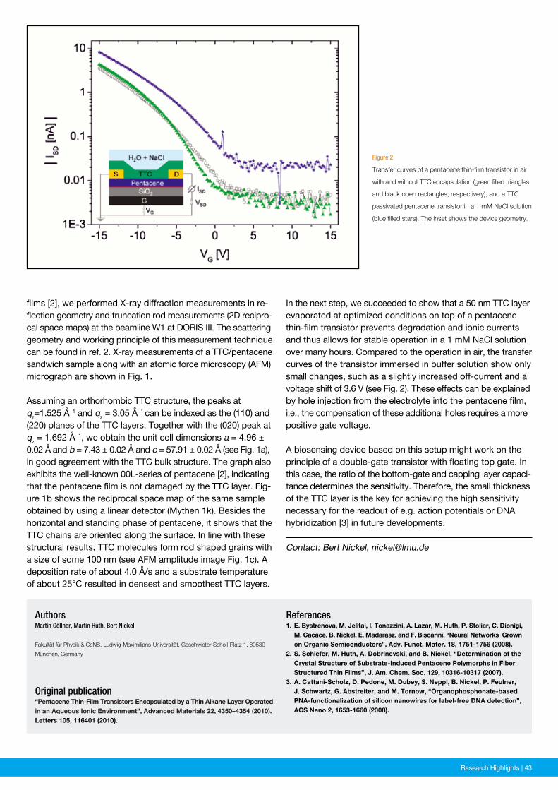
News and Events | 43Research Highlights | 43
Figure 2
Transfer curves of a pentacene thin-film transistor in air
with and without TTC encapsulation (green filled triangles
and black open rectangles, respectively), and a TTC
passivated pentacene transistor in a 1 mM NaCl solution
(blue filled stars). The inset shows the device geometry.
References1. E. Bystrenova, M. Jelitai, I. Tonazzini, A. Lazar, M. Huth, P. Stoliar, C. Dionigi, M. Cacace, B. Nickel, E. Madarasz, and F. Biscarini, “Neural Networks Grown on Organic Semiconductors”, Adv. Funct. Mater. 18, 1751-1756 (2008).2. S. Schiefer, M. Huth, A. Dobrinevski, and B. Nickel, “Determination of the Crystal Structure of Substrate-Induced Pentacene Polymorphs in Fiber Structured Thin Films”, J. Am. Chem. Soc. 129, 10316-10317 (2007).3. A. Cattani-Scholz, D. Pedone, M. Dubey, S. Neppl, B. Nickel, P. Feulner, J. Schwartz, G. Abstreiter, and M. Tornow, “Organophosphonate-based PNA-functionalization of silicon nanowires for label-free DNA detection”, ACS Nano 2, 1653-1660 (2008).
AuthorsMartin Göllner, Martin Huth, Bert Nickel
Fakultät für Physik & CeNS, Ludwig-Maximilians-Universität, Geschwister-Scholl-Platz 1, 80539
München, Germany
Original publication“Pentacene Thin-Film Transistors Encapsulated by a Thin Alkane Layer Operated in an Aqueous Ionic Environment”, Advanced Materials 22, 4350–4354 (2010). Letters 105, 116401 (2010).
films [2], we performed X-ray diffraction measurements in re-flection geometry and truncation rod measurements (2D recipro-cal space maps) at the beamline W1 at DORIS III. The scattering geometry and working principle of this measurement technique can be found in ref. 2. X-ray measurements of a TTC/pentacene sandwich sample along with an atomic force microscopy (AFM) micrograph are shown in Fig. 1.
Assuming an orthorhombic TTC structure, the peaks at qz=1.525 Å−1 and qz = 3.05 Å−1 can be indexed as the (110) and (220) planes of the TTC layers. Together with the (020) peak at qz = 1.692 Å−1, we obtain the unit cell dimensions a = 4.96 ± 0.02 Å and b = 7.43 ± 0.02 Å and c = 57.91 ± 0.02 Å (see Fig. 1a), in good agreement with the TTC bulk structure. The graph also exhibits the well-known 00L-series of pentacene [2], indicating that the pentacene film is not damaged by the TTC layer. Fig-ure 1b shows the reciprocal space map of the same sample obtained by using a linear detector (Mythen 1k). Besides the horizontal and standing phase of pentacene, it shows that the TTC chains are oriented along the surface. In line with these structural results, TTC molecules form rod shaped grains with a size of some 100 nm (see AFM amplitude image Fig. 1c). A deposition rate of about 4.0 Å/s and a substrate temperature of about 25°C resulted in densest and smoothest TTC layers.
Contact: Bert Nickel, [email protected]
In the next step, we succeeded to show that a 50 nm TTC layer evaporated at optimized conditions on top of a pentacene thin-film transistor prevents degradation and ionic currents and thus allows for stable operation in a 1 mM NaCl solution over many hours. Compared to the operation in air, the transfer curves of the transistor immersed in buffer solution show only small changes, such as a slightly increased off-current and a voltage shift of 3.6 V (see Fig. 2). These effects can be explained by hole injection from the electrolyte into the pentacene film, i.e., the compensation of these additional holes requires a more positive gate voltage.
A biosensing device based on this setup might work on the principle of a double-gate transistor with floating top gate. In this case, the ratio of the bottom-gate and capping layer capaci-tance determines the sensitivity. Therefore, the small thickness of the TTC layer is the key for achieving the high sensitivity necessary for the readout of e.g. action potentials or DNA hybridization [3] in future developments.
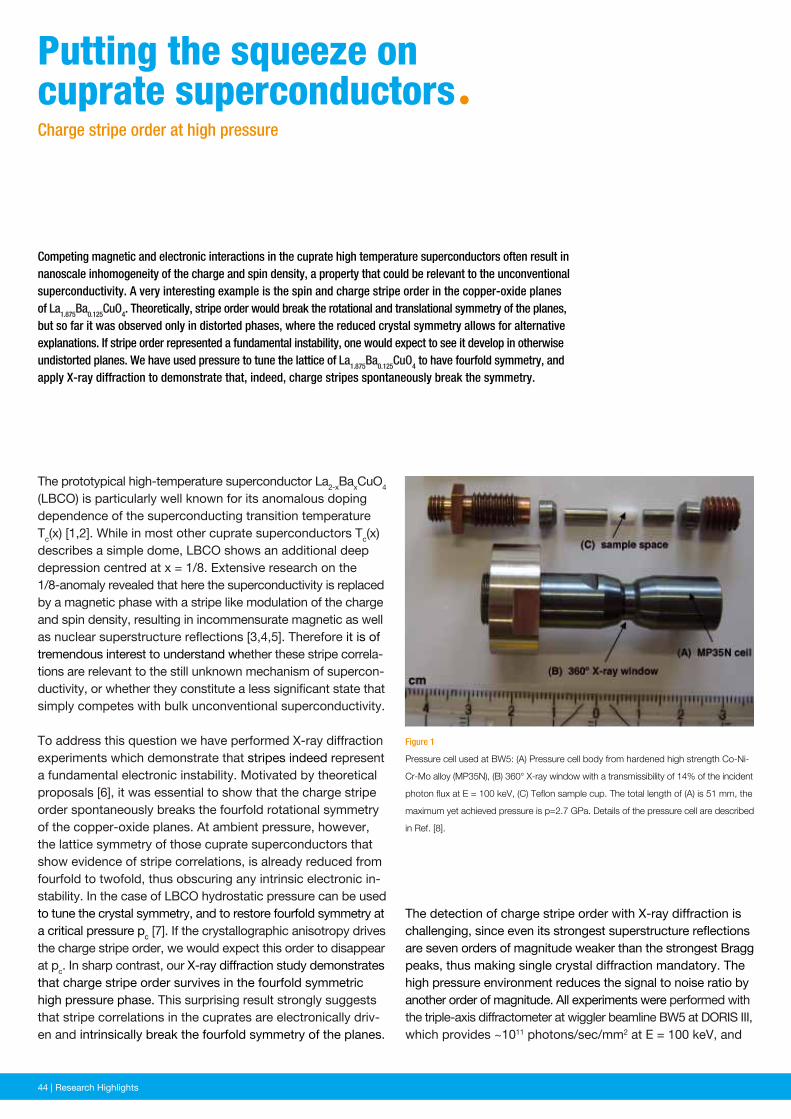
44 | News and Events44 | Research Highlights
The detection of charge stripe order with X-ray diffraction is challenging, since even its strongest superstructure reflections are seven orders of magnitude weaker than the strongest Bragg peaks, thus making single crystal diffraction mandatory. The high pressure environment reduces the signal to noise ratio by another order of magnitude. All experiments were performed with the triple-axis diffractometer at wiggler beamline BW5 at DORIS III, which provides ~1011 photons/sec/mm2 at E = 100 keV, and
Figure 1
Pressure cell used at BW5: (A) Pressure cell body from hardened high strength Co-Ni-
Cr-Mo alloy (MP35N), (B) 360° X-ray window with a transmissibility of 14% of the incident
photon flux at E = 100 keV, (C) Teflon sample cup. The total length of (A) is 51 mm, the
maximum yet achieved pressure is p=2.7 GPa. Details of the pressure cell are described
in Ref. [8].
Competing magnetic and electronic interactions in the cuprate high temperature superconductors often result in nanoscale inhomogeneity of the charge and spin density, a property that could be relevant to the unconventional superconductivity. A very interesting example is the spin and charge stripe order in the copper-oxide planes of La1.875Ba0.125CuO4. Theoretically, stripe order would break the rotational and translational symmetry of the planes, but so far it was observed only in distorted phases, where the reduced crystal symmetry allows for alternative explanations. If stripe order represented a fundamental instability, one would expect to see it develop in otherwise undistorted planes. We have used pressure to tune the lattice of La1.875Ba0.125CuO4 to have fourfold symmetry, and apply X-ray diffraction to demonstrate that, indeed, charge stripes spontaneously break the symmetry.
The prototypical high-temperature superconductor La2-xBaxCuO4 (LBCO) is particularly well known for its anomalous doping dependence of the superconducting transition temperature Tc(x) [1,2]. While in most other cuprate superconductors Tc(x) describes a simple dome, LBCO shows an additional deep depression centred at x = 1/8. Extensive research on the 1/8-anomaly revealed that here the superconductivity is replaced by a magnetic phase with a stripe like modulation of the charge and spin density, resulting in incommensurate magnetic as well as nuclear superstructure reflections [3,4,5]. Therefore it is of tremendous interest to understand whether these stripe correla-tions are relevant to the still unknown mechanism of supercon-ductivity, or whether they constitute a less significant state that simply competes with bulk unconventional superconductivity.
To address this question we have performed X-ray diffraction experiments which demonstrate that stripes indeed represent a fundamental electronic instability. Motivated by theoretical proposals [6], it was essential to show that the charge stripe order spontaneously breaks the fourfold rotational symmetry of the copper-oxide planes. At ambient pressure, however, the lattice symmetry of those cuprate superconductors that show evidence of stripe correlations, is already reduced from fourfold to twofold, thus obscuring any intrinsic electronic in-stability. In the case of LBCO hydrostatic pressure can be used to tune the crystal symmetry, and to restore fourfold symmetry at a critical pressure pc [7]. If the crystallographic anisotropy drives the charge stripe order, we would expect this order to disappear at pc. In sharp contrast, our X-ray diffraction study demonstrates that charge stripe order survives in the fourfold symmetric high pressure phase. This surprising result strongly suggests that stripe correlations in the cuprates are electronically driv-en and intrinsically break the fourfold symmetry of the planes.
putting the squeeze on cuprate superconductorsªCharge stripe order at high pressure
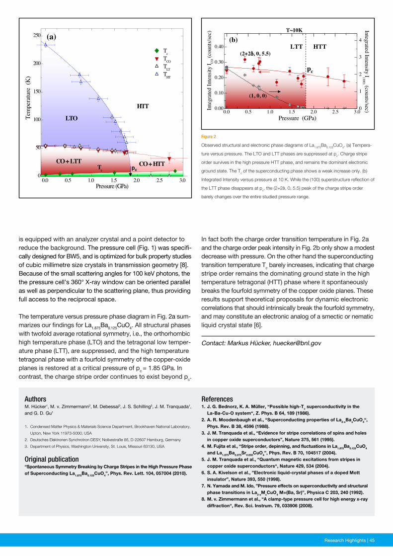
News and Events | 45Research Highlights | 45
Figure 2
Observed structural and electronic phase diagrams of La1.875Ba0.125CuO4. (a) Tempera-
ture versus pressure. The LTO and LTT phases are suppressed at pc. Charge stripe
order survives in the high pressure HTT phase, and remains the dominant electronic
ground state. The Tc of the superconducting phase shows a weak increase only. (b)
Integrated Intensity versus pressure at 10 K. While the (100) superstructure reflection of
the LTT phase disappears at pc, the (2+2δ, 0, 5.5) peak of the charge stripe order
barely changes over the entire studied pressure range.
References1. J. G. Bednorz, K. A. Müller, “Possible high-Tc superconductivity in the La-Ba-Cu-O system“, Z. Phys. B 64, 189 (1986).2. A. R. Moodenbaugh et al., “Superconducting properties of La2-xBaxCuO4“, Phys. Rev. B 38, 4596 (1988).3. J. M. Tranquada et al., “Evidence for stripe correlations of spins and holes in copper oxide superconductors”, Nature 375, 561 (1995).4. M. Fujita et al., “Stripe order, depinning, and fluctuations in La1.875Ba0.125CuO4
and La1.875Ba0.075Sr0.050CuO4”, Phys. Rev. B 70, 104517 (2004).5. J. M. Tranquada et al., “Quantum magnetic excitations from stripes in copper oxide superconductors“, Nature 429, 534 (2004).6. S. A. Kivelson et al., ”Electronic liquid-crystal phases of a doped Mott insulator”, Nature 393, 550 (1998).7. N. Yamada and M. Ido, ”Pressure effects on superconductivity and structural phase transitions in La2-xMxCuO4 M=(Ba, Sr)”, Physica C 203, 240 (1992).8. M. v. Zimmermann et al., “A clamp-type pressure cell for high energy x-ray diffraction“, Rev. Sci. Instrum. 79, 033906 (2008).
AuthorsM. Hücker1, M. v. Zimmermann2, M. Debessai3, J. S. Schilling3, J. M. Tranquada1, and G. D. Gu1
1. Condensed Matter Physics & Materials Science Department, Brookhaven National Laboratory,
Upton, New York 11973-5000, USA
2. Deutsches Elektronen Synchrotron DESY, Notkestraße 85, D-22607 Hamburg, Germany
3. Department of Physics, Washington University, St. Louis, Missouri 63130, USA
Original publication“Spontaneous Symmetry Breaking by Charge Stripes in the High Pressure Phase of Superconducting La1.875Ba0.125CuO4”, Phys. Rev. Lett. 104, 057004 (2010).
is equipped with an analyzer crystal and a point detector to reduce the background. The pressure cell (Fig. 1) was specifi-cally designed for BW5, and is optimized for bulk property studies of cubic millimetre size crystals in transmission geometry [8]. Because of the small scattering angles for 100 keV photons, the the pressure cell’s 360° X-ray window can be oriented parallel as well as perpendicular to the scattering plane, thus providing full access to the reciprocal space.
The temperature versus pressure phase diagram in Fig. 2a sum-marizes our findings for La1.875Ba0.125CuO4. All structural phases with twofold average rotational symmetry, i.e., the orthorhombic high temperature phase (LTO) and the tetragonal low temper-ature phase (LTT), are suppressed, and the high temperature tetragonal phase with a fourfold symmetry of the copper-oxide planes is restored at a critical pressure of pc = 1.85 GPa. In contrast, the charge stripe order continues to exist beyond pc.
Contact: Markus Hücker, [email protected]
In fact both the charge order transition temperature in Fig. 2a and the charge order peak intensity in Fig. 2b only show a modest decrease with pressure. On the other hand the superconducting transition temperature Tc barely increases, indicating that charge stripe order remains the dominating ground state in the high temperature tetragonal (HTT) phase where it spontaneously breaks the fourfold symmetry of the copper oxide planes. These results support theoretical proposals for dynamic electronic correlations that should intrinsically break the fourfold symmetry, and may constitute an electronic analog of a smectic or nematic liquid crystal state [6].
pc
0.0 0.5 1.0 1.5 2.0 2.5 3.00
50
100
150
200
250
TcTCOTLTTHT
Pressure (GPa)
TcCO + HTT
LTO
CO + LTT
HTT
Tem
pera
ture
(K
)(a)
pc
T~10K
(1, 0, 0)
(2+2δδδδ, 0, 5.5)LTT HTT
(b)
0.0 0.5 1.0 1.5 2.0 2.5 3.00.00
0.10
0.20
0.30
0.40
Pressure (GPa)
Integ
rated
Inten
sity
I CO (c
ount
s/sec
)
0
1
2
3
4
Integrated Intensity I(100) (counts/sec)
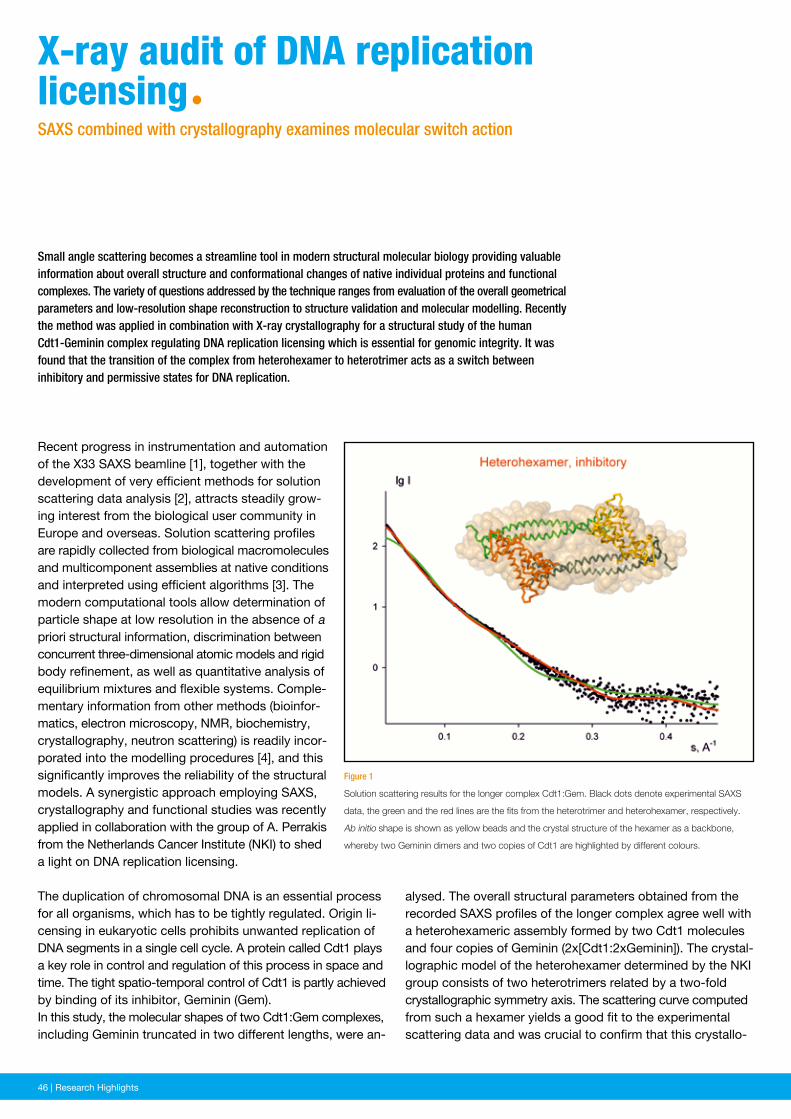
46 | News and Events46 | Research Highlights
alysed. The overall structural parameters obtained from the recorded SAXS profiles of the longer complex agree well with a heterohexameric assembly formed by two Cdt1 molecules and four copies of Geminin (2x[Cdt1:2xGeminin]). The crystal-lographic model of the heterohexamer determined by the NKI group consists of two heterotrimers related by a two-fold crystallographic symmetry axis. The scattering curve computed from such a hexamer yields a good fit to the experimental scattering data and was crucial to confirm that this crystallo-
Figure 1
Solution scattering results for the longer complex Cdt1:Gem. Black dots denote experimental SAXS
data, the green and the red lines are the fits from the heterotrimer and heterohexamer, respectively.
Ab initio shape is shown as yellow beads and the crystal structure of the hexamer as a backbone,
whereby two Geminin dimers and two copies of Cdt1 are highlighted by different colours.
Small angle scattering becomes a streamline tool in modern structural molecular biology providing valuable information about overall structure and conformational changes of native individual proteins and functional complexes. The variety of questions addressed by the technique ranges from evaluation of the overall geometrical parameters and low-resolution shape reconstruction to structure validation and molecular modelling. Recently the method was applied in combination with X-ray crystallography for a structural study of the human Cdt1-Geminin complex regulating DNA replication licensing which is essential for genomic integrity. It was found that the transition of the complex from heterohexamer to heterotrimer acts as a switch between inhibitory and permissive states for DNA replication.
Recent progress in instrumentation and automation of the X33 SAXS beamline [1], together with the development of very efficient methods for solution scattering data analysis [2], attracts steadily grow-ing interest from the biological user community in Europe and overseas. Solution scattering profiles are rapidly collected from biological macromolecules and multicomponent assemblies at native conditions and interpreted using efficient algorithms [3]. The modern computational tools allow determination of particle shape at low resolution in the absence of a priori structural information, discrimination between concurrent three-dimensional atomic models and rigid body refinement, as well as quantitative analysis of equilibrium mixtures and flexible systems. Comple-mentary information from other methods (bioinfor-matics, electron microscopy, NMR, biochemistry, crystallography, neutron scattering) is readily incor-porated into the modelling procedures [4], and this significantly improves the reliability of the structural models. A synergistic approach employing SAXS, crystallography and functional studies was recently applied in collaboration with the group of A. Perrakis from the Netherlands Cancer Institute (NKI) to shed a light on DNA replication licensing.
The duplication of chromosomal DNA is an essential process for all organisms, which has to be tightly regulated. Origin li-censing in eukaryotic cells prohibits unwanted replication of DNA segments in a single cell cycle. A protein called Cdt1 plays a key role in control and regulation of this process in space and time. The tight spatio-temporal control of Cdt1 is partly achieved by binding of its inhibitor, Geminin (Gem).In this study, the molecular shapes of two Cdt1:Gem complexes, including Geminin truncated in two different lengths, were an-
X-ray audit of DnA replication licensingªSAXS combined with crystallography examines molecular switch action
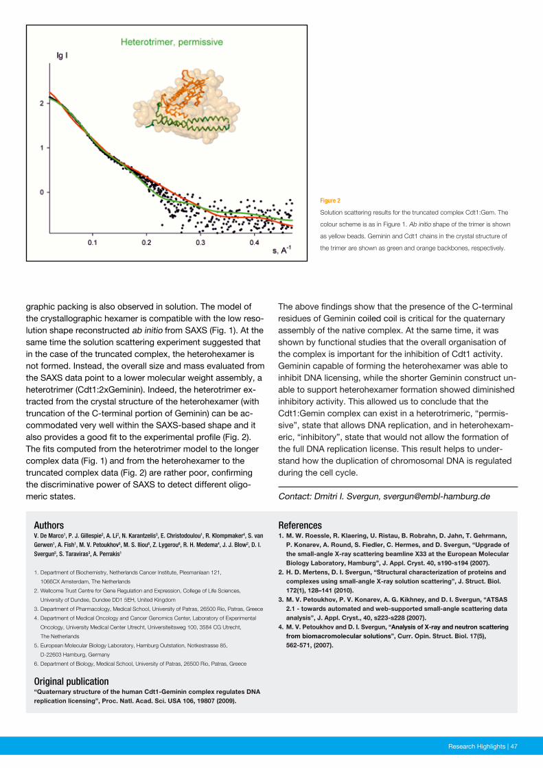
News and Events | 47Research Highlights | 47
Figure 2
Solution scattering results for the truncated complex Cdt1:Gem. The
colour scheme is as in Figure 1. Ab initio shape of the trimer is shown
as yellow beads. Geminin and Cdt1 chains in the crystal structure of
the trimer are shown as green and orange backbones, respectively.
References1. M. W. Roessle, R. Klaering, U. Ristau, B. Robrahn, D. Jahn, T. Gehrmann, P. Konarev, A. Round, S. Fiedler, C. Hermes, and D. Svergun, “Upgrade of the small-angle X-ray scattering beamline X33 at the European Molecular Biology Laboratory, Hamburg”, J. Appl. Cryst. 40, s190-s194 (2007).2. H. D. Mertens, D. I. Svergun, “Structural characterization of proteins and complexes using small-angle X-ray solution scattering”, J. Struct. Biol. 172(1), 128–141 (2010).3. M. V. Petoukhov, P. V. Konarev, A. G. Kikhney, and D. I. Svergun, “ATSAS 2.1 - towards automated and web-supported small-angle scattering data analysis”, J. Appl. Cryst., 40, s223-s228 (2007).4. M. V. Petoukhov and D. I. Svergun, “Analysis of X-ray and neutron scattering from biomacromolecular solutions”, Curr. Opin. Struct. Biol. 17(5), 562-571, (2007).
AuthorsV. De Marco1, P. J. Gillespie2, A. Li2, N. Karantzelis3, E. Christodoulou1, R. Klompmaker4, S. van Gerwen1, A. Fish1, M. V. Petoukhov5, M. S. Iliou6, Z. Lygerou6, R. H. Medema4, J. J. Blow2, D. I. Svergun5, S. Taraviras3, A. Perrakis1
1. Department of Biochemistry, Netherlands Cancer Institute, Plesmanlaan 121,
1066CX Amsterdam, The Netherlands
2. Wellcome Trust Centre for Gene Regulation and Expression, College of Life Sciences,
University of Dundee, Dundee DD1 5EH, United Kingdom
3. Department of Pharmacology, Medical School, University of Patras, 26500 Rio, Patras, Greece
4. Department of Medical Oncology and Cancer Genomics Center, Laboratory of Experimental
Oncology, University Medical Center Utrecht, Universiteitsweg 100, 3584 CG Utrecht,
The Netherlands
5. European Molecular Biology Laboratory, Hamburg Outstation, Notkestrasse 85,
D-22603 Hamburg, Germany
6. Department of Biology, Medical School, University of Patras, 26500 Rio, Patras, Greece
Original publication“Quaternary structure of the human Cdt1-Geminin complex regulates DNA replication licensing”, Proc. Natl. Acad. Sci. USA 106, 19807 (2009).
graphic packing is also observed in solution. The model of the crystallographic hexamer is compatible with the low reso-lution shape reconstructed ab initio from SAXS (Fig. 1). At the same time the solution scattering experiment suggested that in the case of the truncated complex, the heterohexamer is not formed. Instead, the overall size and mass evaluated from the SAXS data point to a lower molecular weight assembly, a heterotrimer (Cdt1:2xGeminin). Indeed, the heterotrimer ex-tracted from the crystal structure of the heterohexamer (with truncation of the C-terminal portion of Geminin) can be ac-commodated very well within the SAXS-based shape and it also provides a good fit to the experimental profile (Fig. 2). The fits computed from the heterotrimer model to the longer complex data (Fig. 1) and from the heterohexamer to the truncated complex data (Fig. 2) are rather poor, confirming the discriminative power of SAXS to detect different oligo-meric states. Contact: Dmitri I. Svergun, [email protected]
The above findings show that the presence of the C-terminal residues of Geminin coiled coil is critical for the quaternary assembly of the native complex. At the same time, it was shown by functional studies that the overall organisation of the complex is important for the inhibition of Cdt1 activity. Geminin capable of forming the heterohexamer was able to inhibit DNA licensing, while the shorter Geminin construct un-able to support heterohexamer formation showed diminished inhibitory activity. This allowed us to conclude that the Cdt1:Gemin complex can exist in a heterotrimeric, “permis-sive”, state that allows DNA replication, and in heterohexam-eric, “inhibitory”, state that would not allow the formation of the full DNA replication license. This result helps to under-stand how the duplication of chromosomal DNA is regulated during the cell cycle.
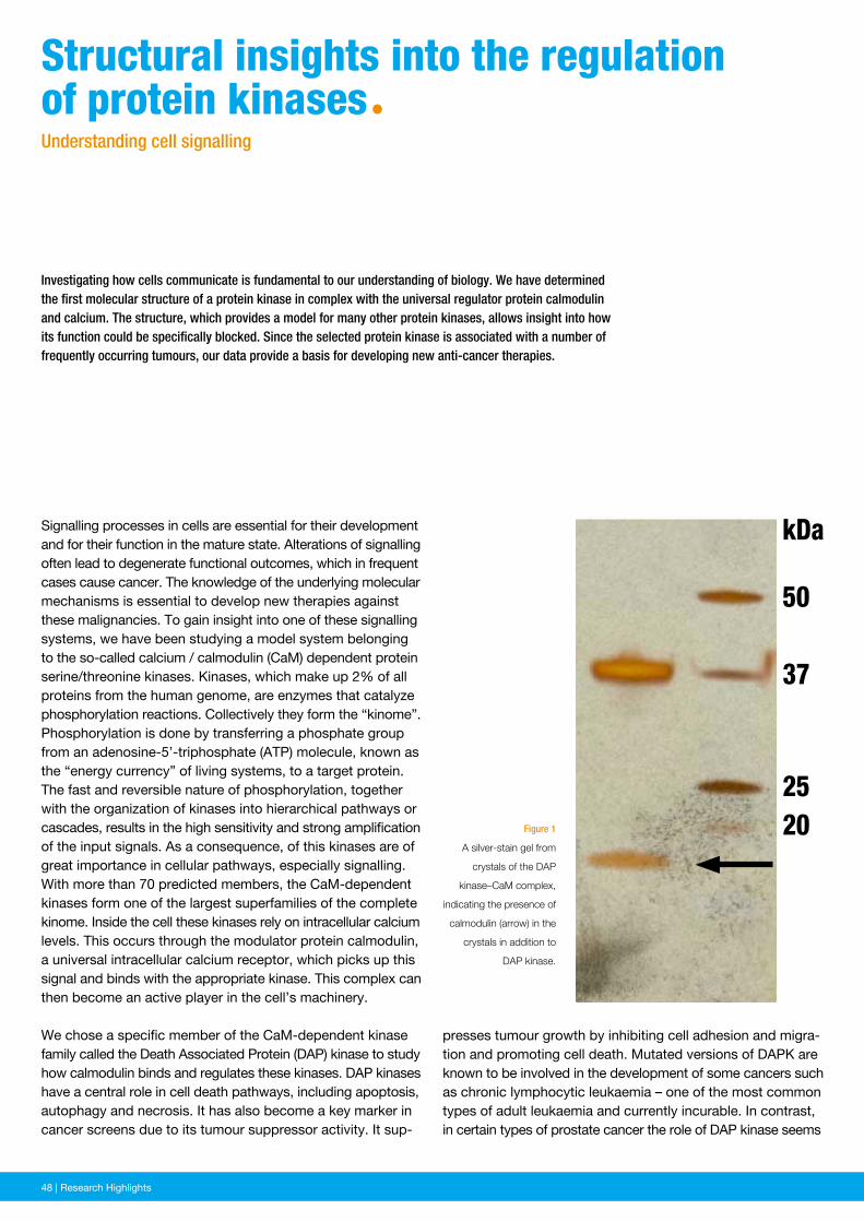
48 | News and Events48 | Research Highlights
Figure 1
A silver-stain gel from
crystals of the DAP
kinase–CaM complex,
indicating the presence of
calmodulin (arrow) in the
crystals in addition to
DAP kinase.
Investigating how cells communicate is fundamental to our understanding of biology. We have determined the first molecular structure of a protein kinase in complex with the universal regulator protein calmodulin and calcium. The structure, which provides a model for many other protein kinases, allows insight into how its function could be specifically blocked. Since the selected protein kinase is associated with a number of frequently occurring tumours, our data provide a basis for developing new anti-cancer therapies.
Signalling processes in cells are essential for their development and for their function in the mature state. Alterations of signalling often lead to degenerate functional outcomes, which in frequent cases cause cancer. The knowledge of the underlying molecular mechanisms is essential to develop new therapies against these malignancies. To gain insight into one of these signalling systems, we have been studying a model system belonging to the so-called calcium / calmodulin (CaM) dependent protein serine/threonine kinases. Kinases, which make up 2% of all proteins from the human genome, are enzymes that catalyze phosphorylation reactions. Collectively they form the “kinome”. Phosphorylation is done by transferring a phosphate group from an adenosine-5’-triphosphate (ATP) molecule, known as the “energy currency” of living systems, to a target protein. The fast and reversible nature of phosphorylation, together with the organization of kinases into hierarchical pathways or cascades, results in the high sensitivity and strong amplification of the input signals. As a consequence, of this kinases are of great importance in cellular pathways, especially signalling. With more than 70 predicted members, the CaM-dependent kinases form one of the largest superfamilies of the complete kinome. Inside the cell these kinases rely on intracellular calcium levels. This occurs through the modulator protein calmodulin, a universal intracellular calcium receptor, which picks up this signal and binds with the appropriate kinase. This complex can then become an active player in the cell’s machinery.
We chose a specific member of the CaM-dependent kinase family called the Death Associated Protein (DAP) kinase to study how calmodulin binds and regulates these kinases. DAP kinases have a central role in cell death pathways, including apoptosis, autophagy and necrosis. It has also become a key marker in cancer screens due to its tumour suppressor activity. It sup-
structural insights into the regulation of protein kinasesªUnderstanding cell signalling
presses tumour growth by inhibiting cell adhesion and migra-tion and promoting cell death. Mutated versions of DAPK are known to be involved in the development of some cancers such as chronic lymphocytic leukaemia – one of the most common types of adult leukaemia and currently incurable. In contrast, in certain types of prostate cancer the role of DAP kinase seems
kDa
50
37
2520
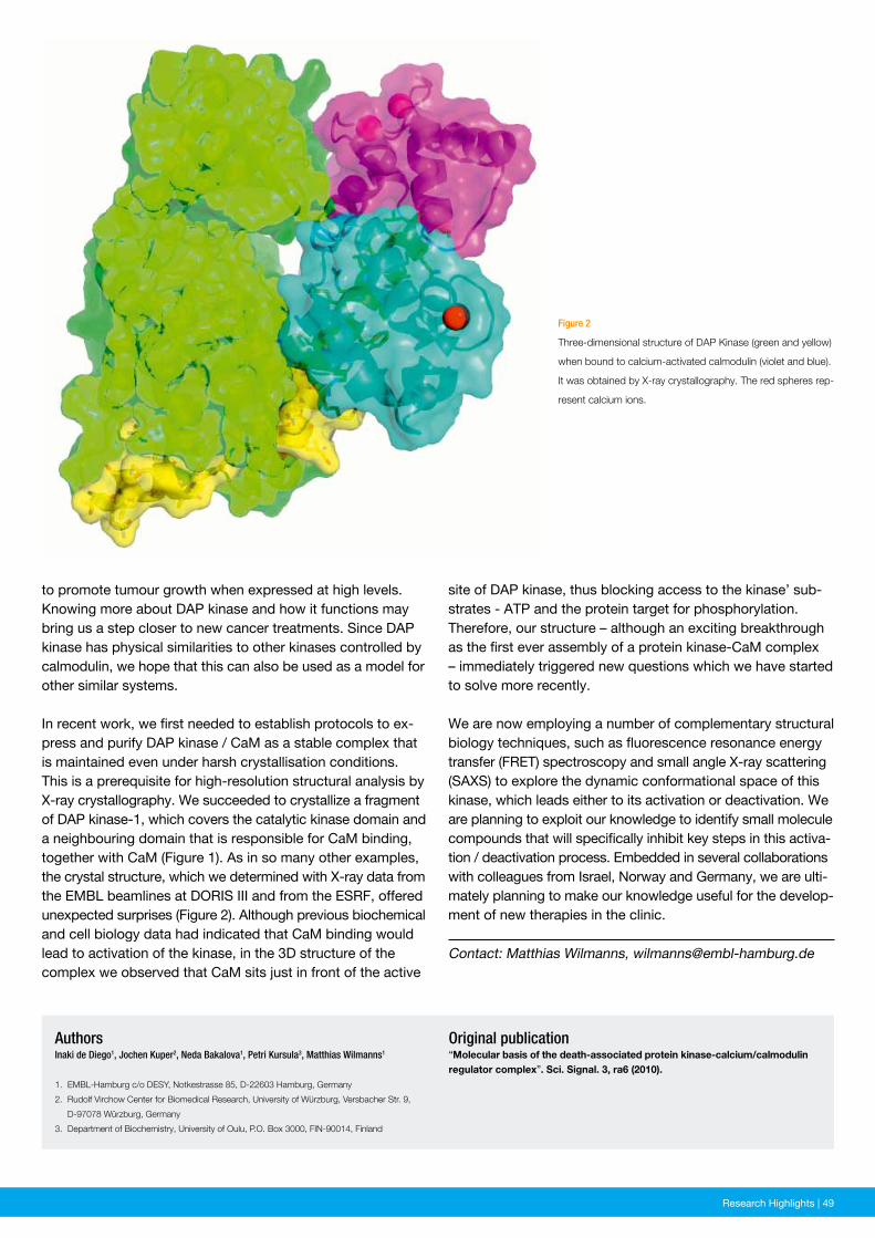
News and Events | 49Research Highlights | 49
Figure 2
Three-dimensional structure of DAP Kinase (green and yellow)
when bound to calcium-activated calmodulin (violet and blue).
It was obtained by X-ray crystallography. The red spheres rep-
resent calcium ions.
Original publication“Molecular basis of the death-associated protein kinase-calcium/calmodulin regulator complex”. Sci. Signal. 3, ra6 (2010).
AuthorsInaki de Diego1, Jochen Kuper2, Neda Bakalova1, Petri Kursula3, Matthias Wilmanns1
1. EMBL-Hamburg c/o DESY, Notkestrasse 85, D-22603 Hamburg, Germany
2. Rudolf Virchow Center for Biomedical Research, University of Würzburg, Versbacher Str. 9,
D-97078 Würzburg, Germany
3. Department of Biochemistry, University of Oulu, P.O. Box 3000, FIN-90014, Finland
Contact: Matthias Wilmanns, [email protected]
to promote tumour growth when expressed at high levels. Knowing more about DAP kinase and how it functions may bring us a step closer to new cancer treatments. Since DAP kinase has physical similarities to other kinases controlled by calmodulin, we hope that this can also be used as a model for other similar systems.
In recent work, we first needed to establish protocols to ex-press and purify DAP kinase / CaM as a stable complex that is maintained even under harsh crystallisation conditions. This is a prerequisite for high-resolution structural analysis by X-ray crystallography. We succeeded to crystallize a fragment of DAP kinase-1, which covers the catalytic kinase domain and a neighbouring domain that is responsible for CaM binding, together with CaM (Figure 1). As in so many other examples, the crystal structure, which we determined with X-ray data from the EMBL beamlines at DORIS III and from the ESRF, offered unexpected surprises (Figure 2). Although previous biochemical and cell biology data had indicated that CaM binding would lead to activation of the kinase, in the 3D structure of the complex we observed that CaM sits just in front of the active
site of DAP kinase, thus blocking access to the kinase’ sub-strates - ATP and the protein target for phosphorylation. Therefore, our structure – although an exciting breakthrough as the first ever assembly of a protein kinase-CaM complex – immediately triggered new questions which we have started to solve more recently.
We are now employing a number of complementary structural biology techniques, such as fluorescence resonance energy transfer (FRET) spectroscopy and small angle X-ray scattering (SAXS) to explore the dynamic conformational space of this kinase, which leads either to its activation or deactivation. We are planning to exploit our knowledge to identify small molecule compounds that will specifically inhibit key steps in this activa-tion / deactivation process. Embedded in several collaborations with colleagues from Israel, Norway and Germany, we are ulti - mately planning to make our knowledge useful for the develop- ment of new therapies in the clinic.
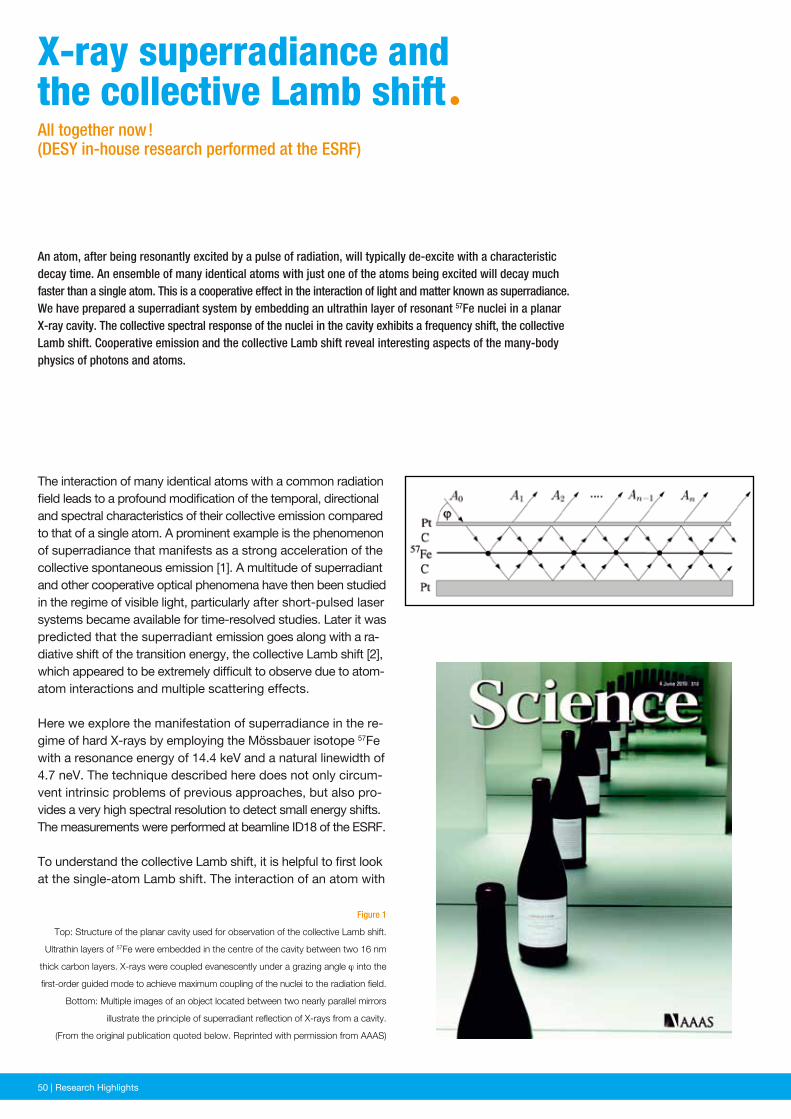
50 | News and Events50 | Research Highlights
Figure 1
Top: Structure of the planar cavity used for observation of the collective Lamb shift.
Ultrathin layers of 57Fe were embedded in the centre of the cavity between two 16 nm
thick carbon layers. X-rays were coupled evanescently under a grazing angle ϕ into the
first-order guided mode to achieve maximum coupling of the nuclei to the radiation field.
Bottom: Multiple images of an object located between two nearly parallel mirrors
illustrate the principle of superradiant reflection of X-rays from a cavity.
(From the original publication quoted below. Reprinted with permission from AAAS)
An atom, after being resonantly excited by a pulse of radiation, will typically de-excite with a characteristic decay time. An ensemble of many identical atoms with just one of the atoms being excited will decay much faster than a single atom. This is a cooperative effect in the interaction of light and matter known as super radiance. We have prepared a superradiant system by embedding an ultrathin layer of resonant 57Fe nuclei in a planar X-ray cavity. The collective spectral response of the nuclei in the cavity exhibits a frequency shift, the collective Lamb shift. Cooperative emission and the collective Lamb shift reveal interesting aspects of the many-body physics of photons and atoms.
The interaction of many identical atoms with a common radiation field leads to a profound modification of the temporal, directional and spectral characteristics of their collective emission compared to that of a single atom. A prominent example is the phenomenon of superradiance that manifests as a strong acceleration of the collective spontaneous emission [1]. A multitude of superradiant and other cooperative optical phenomena have then been studied in the regime of visible light, particularly after short-pulsed laser systems became available for time-resolved studies. Later it was predicted that the superradiant emission goes along with a ra-diative shift of the transition energy, the collective Lamb shift [2], which appeared to be extremely difficult to observe due to atom-atom interactions and multiple scattering effects.
Here we explore the manifestation of superradiance in the re-gime of hard X-rays by employing the Mössbauer isotope 57Fe with a resonance energy of 14.4 keV and a natural linewidth of 4.7 neV. The technique described here does not only circum-vent intrinsic problems of previous approaches, but also pro-vides a very high spectral resolution to detect small energy shifts. The measurements were performed at beamline ID18 of the ESRF.
To understand the collective Lamb shift, it is helpful to first look at the single-atom Lamb shift. The interaction of an atom with
X-ray superradiance and the collective Lamb shiftªAll together now ! (DESY in-house research performed at the ESRF)
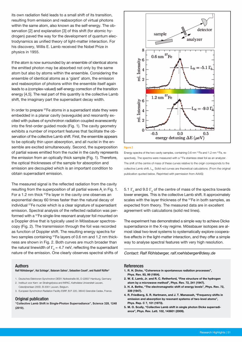
News and Events | 51Research Highlights | 51
Figure 2
Energy spectra of the two cavity samples, containing 0.6 nm 57Fe and 1.2 nm 57Fe, re-
spectively. The spectra were measured with a 57Fe stainless steel foil as an analyzer.
The shift of the centre of mass of these curves relative to the origin corresponds to the
collective Lamb shift, LN. Solid red curves are theoretical calculations. (From the original
publication quoted below. Reprinted with permission from AAAS)
its own radiation field leads to a small shift of its transition, resulting from emission and reabsorption of virtual photons within the same atom, also known as the self-energy. The ob-servation [2] and explanation [3] of this shift (for atomic hy-drogen) paved the way for the development of quantum elec-trodynamics as unified theory of light-matter interaction. For his discovery, Willis E. Lamb received the Nobel Prize in physics in 1955.
If the atom is now surrounded by an ensemble of identical atoms the emitted photon may be absorbed not only by the same atom but also by atoms within the ensemble. Considering the ensemble of identical atoms as a ‘giant’ atom, the emission and reabsorption of photons within the ensemble itself again leads to a (complex-valued) self-energy correction of the transition energy [4,5]. The real part of this quantity is the collective Lamb shift, the imaginary part the superradiant decay width.
In order to prepare 57Fe atoms in a superradiant state they were embedded in a planar cavity (waveguide) and resonantly ex-cited with pulses of synchrotron radiation coupled evanescently into the first-order guided mode (Fig. 1). The cavity geometry exhibits a number of important features that facilitate the ob-servation of the collective Lamb shift. First, the ensemble appears to be optically thin upon absorption, and all nuclei in the en-semble are excited simultaneously. Second, the superposition of partial waves emitted from the nuclei in the cavity represents the emission from an optically thick sample (Fig. 1). Therefore, the optical thicknesses of the sample for absorption and emission are decoupled which is an important condition to obtain superradiant emission.
The measured signal is the reflected radiation from the cavity resulting from the superposition of all partial waves Ai in Fig. 1. For a 1.2 nm thick 57Fe layer in the cavity one observes an exponential decay 60 times faster than the natural decay of individual 57Fe nuclei which is a clear signature of superradiant emission. Spectral analysis of the reflected radiation was per-formed with a 57Fe single-line resonant analyzer foil mounted on a Doppler drive that is typically used in Mössbauer spectros-copy (Fig. 2). The transmission through the foil was recorded as function of Doppler shift. The resulting energy spectra for two samples containing 57Fe layers of 0.6 nm and 1.2 nm thick-ness are shown in Fig. 2. Both curves are much broader than the natural linewidth of Γ0 = 4.7 neV, reflecting the superradiant nature of the emission. One clearly observes spectral shifts of
References1. R. H. Dicke, “Coherence in spontaneous radiation processes”, Phys. Rev. 93, 99 (1954).2. W. E. Lamb, Jr. and R. C. Retherford, “Fine structure of the hydrogen atom by a microwave method”, Phys. Rev. 72, 241 (1947).3. H. A. Bethe, “The electromagnetic shift of energy levels”, Phys. Rev. 72, 339 (1947).4. R. Friedberg, S. R. Hartmann, and J. T. Manassah, “Frequency shifts in emission and absorption by resonant systems of two-level atoms”, Phys. Rep. C 7, 101 (1973).5. M. O. Scully, “Collective Lamb shift in single photon Dicke superradi- ance”, Phys. Rev. Lett. 102, 143601 (2009).
AuthorsRalf Röhlsberger1, Kai Schlage1, Balaram Sahoo1, Sebastien Couet2, and Rudolf Rüffer3
1. Deutsches Elektronen Synchrotron DESY, Notkestraße 85, D-22607 Hamburg, Germany
2. Instituut voor Kern- en Stralingsfysica and INPAC, Katholieke Universiteit Leuven,
Celestijnenlaan 200D, B-3001 Leuven, Belgium.
3. European Synchrotron Radiation Facility ESRF, B.P. 220, 38043 Grenoble Cedex, France.
Original publication“Collective Lamb Shift in Single-Photon Superradiance”, Science 328, 1248 (2010).
5.1 Γ0 and 9.0 Γ0 of the centre of mass of the spectra towards lower energies. This is the collective Lamb shift. It approximately scales with the layer thickness of the 57Fe in both samples, as expected from theory. The measured data are in excellent agreement with calculations (solid red lines).
The experiment has demonstrated a simple way to achieve Dicke superradiance in the X-ray regime. Mössbauer isotopes are al-most ideal two-level systems to systematically explore coopera-tive effects in the light-matter interaction, and they offer a simple way to analyse spectral features with very high resolution.
Contact: Ralf Röhlsberger, [email protected]
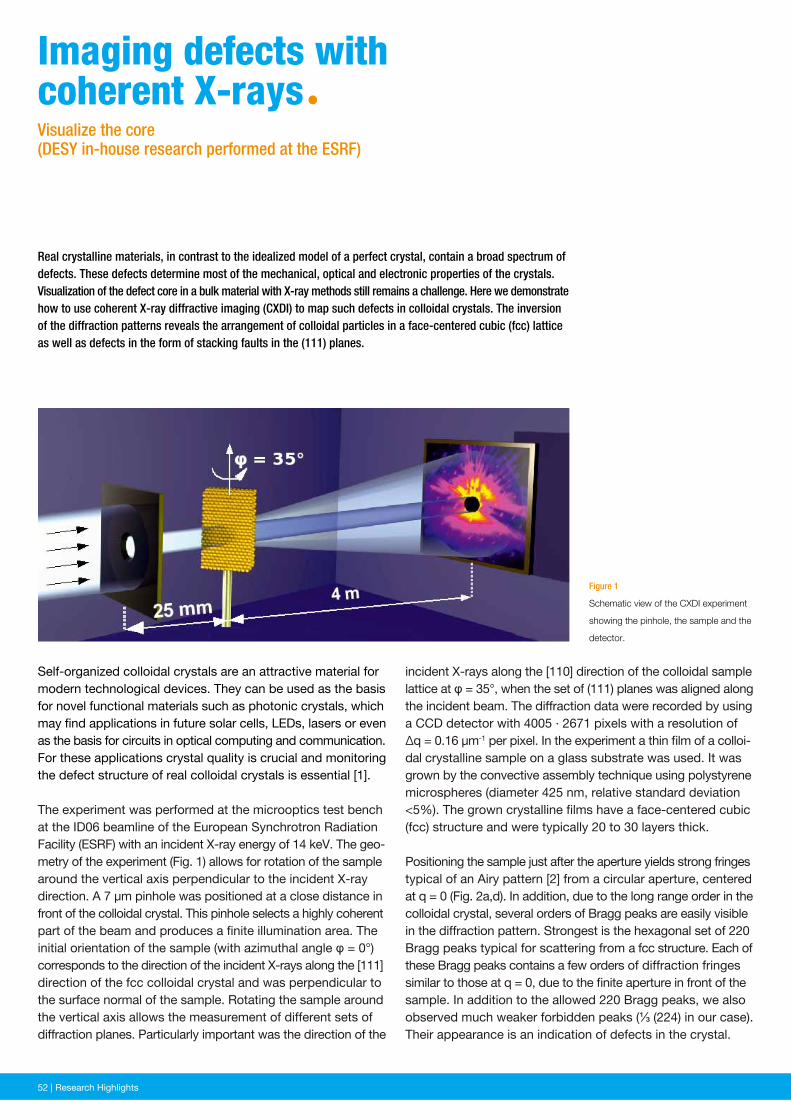
52 | News and Events52 | Research Highlights
incident X-rays along the [110] direction of the colloidal sample lattice at φ = 35°, when the set of (111) planes was aligned along the incident beam. The diffraction data were recorded by using a CCD detector with 4005 · 2671 pixels with a resolution of Δq = 0.16 µm-1 per pixel. In the experiment a thin film of a colloi-dal crystalline sample on a glass substrate was used. It was grown by the convective assembly technique using polystyrene microspheres (diameter 425 nm, relative standard deviation <5%). The grown crystalline films have a face-centered cubic (fcc) structure and were typically 20 to 30 layers thick.
Positioning the sample just after the aperture yields strong fringes typical of an Airy pattern [2] from a circular aperture, centered at q = 0 (Fig. 2a,d). In addition, due to the long range order in the colloidal crystal, several orders of Bragg peaks are easily visible in the diffraction pattern. Strongest is the hexagonal set of 220 Bragg peaks typical for scattering from a fcc structure. Each of these Bragg peaks contains a few orders of diffraction fringes similar to those at q = 0, due to the finite aperture in front of the sample. In addition to the allowed 220 Bragg peaks, we also observed much weaker forbidden peaks (⅓ (224) in our case). Their appearance is an indication of defects in the crystal.
Figure 1
Schematic view of the CXDI experiment
showing the pinhole, the sample and the
detector.
Real crystalline materials, in contrast to the idealized model of a perfect crystal, contain a broad spectrum of defects. These defects determine most of the mechanical, optical and electronic properties of the crystals. Visualization of the defect core in a bulk material with X-ray methods still remains a challenge. Here we demonstrate how to use coherent X-ray diffractive imaging (CXDI) to map such defects in colloidal crystals. The inversion of the diffraction patterns reveals the arrangement of colloidal particles in a face-centered cubic (fcc) lattice as well as defects in the form of stacking faults in the (111) planes.
Self-organized colloidal crystals are an attractive material for modern technological devices. They can be used as the basis for novel functional materials such as photonic crystals, which may find applications in future solar cells, LEDs, lasers or even as the basis for circuits in optical computing and communication. For these applications crystal quality is crucial and monitoring the defect structure of real colloidal crystals is essential [1].
The experiment was performed at the microoptics test bench at the ID06 beamline of the European Synchrotron Radiation Facility (ESRF) with an incident X-ray energy of 14 keV. The geo-metry of the experiment (Fig. 1) allows for rotation of the sample around the vertical axis perpendicular to the incident X-ray direction. A 7 µm pinhole was positioned at a close distance in front of the colloidal crystal. This pinhole selects a highly coherent part of the beam and produces a finite illumination area. The initial orientation of the sample (with azimuthal angle φ = 0°) corresponds to the direction of the incident X-rays along the [111] direction of the fcc colloidal crystal and was perpendicular to the surface normal of the sample. Rotating the sample around the vertical axis allows the measurement of different sets of diffraction planes. Particularly important was the direction of the
imaging defects withcoherent X-raysªVisualize the core (DESY in-house research performed at the ESRF)
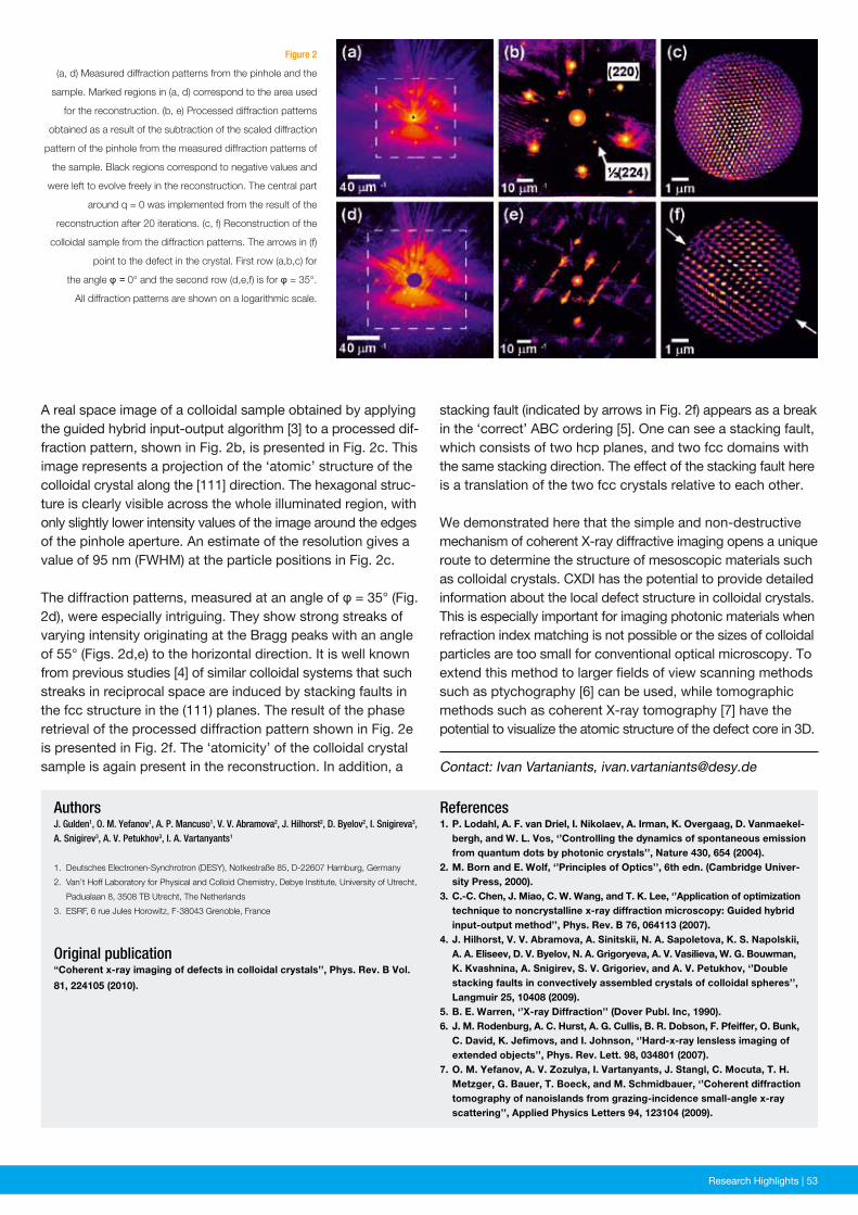
News and Events | 53Research Highlights | 53
Figure 2
(a, d) Measured diffraction patterns from the pinhole and the
sample. Marked regions in (a, d) correspond to the area used
for the reconstruction. (b, e) Processed diffraction patterns
obtained as a result of the subtraction of the scaled diffraction
pattern of the pinhole from the measured diffraction patterns of
the sample. Black regions correspond to negative values and
were left to evolve freely in the reconstruction. The central part
around q = 0 was implemented from the result of the
reconstruction after 20 iterations. (c, f) Reconstruction of the
colloidal sample from the diffraction patterns. The arrows in (f)
point to the defect in the crystal. First row (a,b,c) for
the angle φ = 0° and the second row (d,e,f) is for φ = 35°.
All diffraction patterns are shown on a logarithmic scale.
References1. P. Lodahl, A. F. van Driel, I. Nikolaev, A. Irman, K. Overgaag, D. Vanmaekel- bergh, and W. L. Vos, ‘’Controlling the dynamics of spontaneous emission from quantum dots by photonic crystals’’, Nature 430, 654 (2004).2. M. Born and E. Wolf, ‘’Principles of Optics’’, 6th edn. (Cambridge Univer- sity Press, 2000).3. C.-C. Chen, J. Miao, C. W. Wang, and T. K. Lee, ‘’Application of optimization technique to noncrystalline x-ray diffraction microscopy: Guided hybrid input-output method’’, Phys. Rev. B 76, 064113 (2007).4. J. Hilhorst, V. V. Abramova, A. Sinitskii, N. A. Sapoletova, K. S. Napolskii, A. A. Eliseev, D. V. Byelov, N. A. Grigoryeva, A. V. Vasilieva, W. G. Bouwman, K. Kvashnina, A. Snigirev, S. V. Grigoriev, and A. V. Petukhov, ‘’Double stacking faults in convectively assembled crystals of colloidal spheres’’, Langmuir 25, 10408 (2009).5. B. E. Warren, ‘’X-ray Diffraction’’ (Dover Publ. Inc, 1990).6. J. M. Rodenburg, A. C. Hurst, A. G. Cullis, B. R. Dobson, F. Pfeiffer, O. Bunk, C. David, K. Jefimovs, and I. Johnson, ‘’Hard-x-ray lensless imaging of extended objects’’, Phys. Rev. Lett. 98, 034801 (2007).7. O. M. Yefanov, A. V. Zozulya, I. Vartanyants, J. Stangl, C. Mocuta, T. H. Metzger, G. Bauer, T. Boeck, and M. Schmidbauer, ‘’Coherent diffraction tomography of nanoislands from grazing-incidence small-angle x-ray scattering’’, Applied Physics Letters 94, 123104 (2009).
AuthorsJ. Gulden1, O. M. Yefanov1, A. P. Mancuso1, V. V. Abramova2, J. Hilhorst2, D. Byelov2, I. Snigireva3, A. Snigirev3, A. V. Petukhov3, I. A. Vartanyants1
1. Deutsches Electronen-Synchrotron (DESY), Notkestraße 85, D-22607 Hamburg, Germany
2. Van’t Hoff Laboratory for Physical and Colloid Chemistry, Debye Institute, University of Utrecht,
Padualaan 8, 3508 TB Utrecht, The Netherlands
3. ESRF, 6 rue Jules Horowitz, F-38043 Grenoble, France
Original publication“Coherent x-ray imaging of defects in colloidal crystals’’, Phys. Rev. B Vol.
81, 224105 (2010).
A real space image of a colloidal sample obtained by applying the guided hybrid input-output algorithm [3] to a processed dif-fraction pattern, shown in Fig. 2b, is presented in Fig. 2c. This image represents a projection of the ‘atomic’ structure of the colloidal crystal along the [111] direction. The hexagonal struc-ture is clearly visible across the whole illuminated region, with only slightly lower intensity values of the image around the edges of the pinhole aperture. An estimate of the resolution gives a value of 95 nm (FWHM) at the particle positions in Fig. 2c.
The diffraction patterns, measured at an angle of φ = 35° (Fig. 2d), were especially intriguing. They show strong streaks of varying intensity originating at the Bragg peaks with an angle of 55° (Figs. 2d,e) to the horizontal direction. It is well known from previous studies [4] of similar colloidal systems that such streaks in reciprocal space are induced by stacking faults in the fcc structure in the (111) planes. The result of the phase retrieval of the processed diffraction pattern shown in Fig. 2e is presented in Fig. 2f. The ‘atomicity’ of the colloidal crystal sample is again present in the reconstruction. In addition, a Contact: Ivan Vartaniants, [email protected]
stacking fault (indicated by arrows in Fig. 2f) appears as a break in the ‘correct’ ABC ordering [5]. One can see a stacking fault, which consists of two hcp planes, and two fcc domains with the same stacking direction. The effect of the stacking fault here is a translation of the two fcc crystals relative to each other. We demonstrated here that the simple and non-destructive mechanism of coherent X-ray diffractive imaging opens a unique route to determine the structure of mesoscopic materials such as colloidal crystals. CXDI has the potential to provide detailed information about the local defect structure in colloidal crystals. This is especially important for imaging photonic materials when refraction index matching is not possible or the sizes of colloidal particles are too small for conventional optical microscopy. To extend this method to larger fields of view scanning methods such as ptychography [6] can be used, while tomographic methods such as coherent X-ray tomography [7] have the potential to visualize the atomic structure of the defect core in 3D.
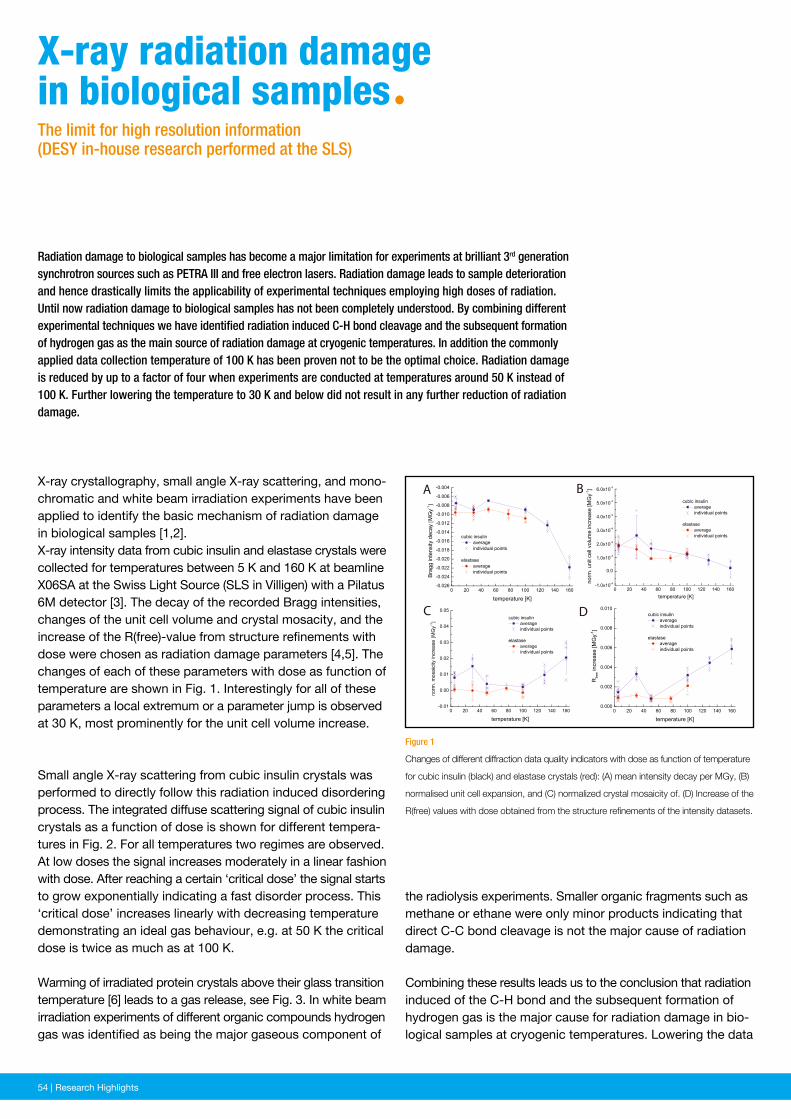
54 | News and Events54 | Research Highlights
the radiolysis experiments. Smaller organic fragments such as methane or ethane were only minor products indicating that direct C-C bond cleavage is not the major cause of radiation damage.
Combining these results leads us to the conclusion that radiation induced of the C-H bond and the subsequent formation of hydrogen gas is the major cause for radiation damage in bio-logical samples at cryogenic temperatures. Lowering the data
Figure 1
Changes of different diffraction data quality indicators with dose as function of temperature
for cubic insulin (black) and elastase crystals (red): (A) mean intensity decay per MGy, (B)
normalised unit cell expansion, and (C) normalized crystal mosaicity of. (D) Increase of the
R(free) values with dose obtained from the structure refinements of the intensity datasets.
Radiation damage to biological samples has become a major limitation for experiments at brilliant 3rd generation synchrotron sources such as PETRA III and free electron lasers. Radiation damage leads to sample deterioration and hence drastically limits the applicability of experimental techniques employing high doses of radiation. Until now radiation damage to biological samples has not been completely understood. By combining different experimental techniques we have identified radiation induced C-H bond cleavage and the subsequent formation of hydrogen gas as the main source of radiation damage at cryogenic temperatures. In addition the commonly applied data collection temperature of 100 K has been proven not to be the optimal choice. Radiation damage is reduced by up to a factor of four when experiments are conducted at temperatures around 50 K instead of 100 K. Further lowering the temperature to 30 K and below did not result in any further reduction of radiation damage.
X-ray crystallography, small angle X-ray scattering, and mono-chromatic and white beam irradiation experiments have been applied to identify the basic mechanism of radiation damage in biological samples [1,2]. X-ray intensity data from cubic insulin and elastase crystals were collected for temperatures between 5 K and 160 K at beamline X06SA at the Swiss Light Source (SLS in Villigen) with a Pilatus 6M detector [3]. The decay of the recorded Bragg intensities, changes of the unit cell volume and crystal mosacity, and the increase of the R(free)-value from structure refinements with dose were chosen as radiation damage parameters [4,5]. The changes of each of these parameters with dose as function of temperature are shown in Fig. 1. Interestingly for all of these parameters a local extremum or a parameter jump is observed at 30 K, most prominently for the unit cell volume increase.
Small angle X-ray scattering from cubic insulin crystals was performed to directly follow this radiation induced disordering process. The integrated diffuse scattering signal of cubic insulin crystals as a function of dose is shown for different tempera-tures in Fig. 2. For all temperatures two regimes are observed. At low doses the signal increases moderately in a linear fashion with dose. After reaching a certain ‘critical dose’ the signal starts to grow exponentially indicating a fast disorder process. This ‘critical dose’ increases linearly with decreasing temperature demonstrating an ideal gas behaviour, e.g. at 50 K the critical dose is twice as much as at 100 K. Warming of irradiated protein crystals above their glass transition temperature [6] leads to a gas release, see Fig. 3. In white beam irradiation experiments of different organic compounds hydrogen gas was identified as being the major gaseous component of
X-ray radiation damage in biological samplesªThe limit for high resolution information(DESY in-house research performed at the SLS)
A B
C D
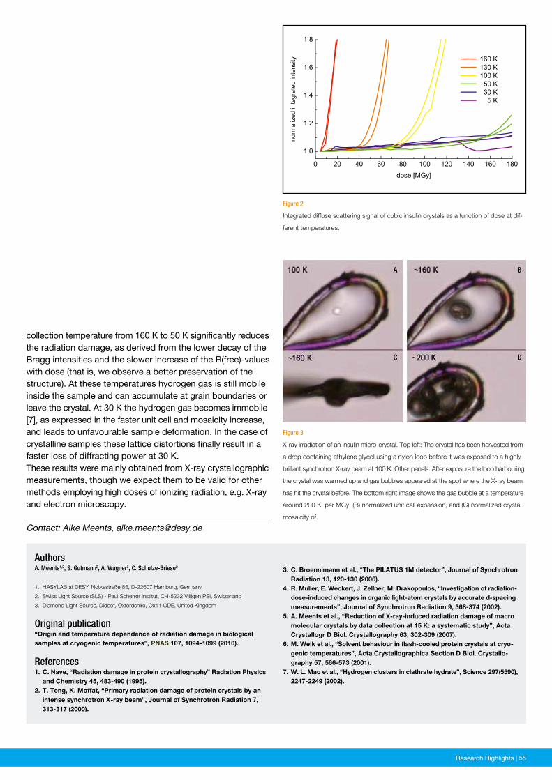
News and Events | 55Research Highlights | 55
Figure 2
Integrated diffuse scattering signal of cubic insulin crystals as a function of dose at dif-
ferent temperatures.
Figure 3
X-ray irradiation of an insulin micro-crystal. Top left: The crystal has been harvested from
a drop containing ethylene glycol using a nylon loop before it was exposed to a highly
brilliant synchrotron X-ray beam at 100 K. Other panels: After exposure the loop harbouring
the crystal was warmed up and gas bubbles appeared at the spot where the X-ray beam
has hit the crystal before. The bottom right image shows the gas bubble at a temperature
around 200 K. per MGy, (B) normalized unit cell expansion, and (C) normalized crystal
mosaicity of.
3. C. Broennimann et al., “The PILATUS 1M detector”, Journal of Synchrotron Radiation 13, 120-130 (2006).4. R. Muller, E. Weckert, J. Zellner, M. Drakopoulos, “Investigation of radiation- dose-induced changes in organic light-atom crystals by accurate d-spacing measurements”, Journal of Synchrotron Radiation 9, 368-374 (2002).5. A. Meents et al., “Reduction of X-ray-induced radiation damage of macro molecular crystals by data collection at 15 K: a systematic study”, Acta Crystallogr D Biol. Crystallography 63, 302-309 (2007).6. M. Weik et al., “Solvent behaviour in flash-cooled protein crystals at cryo- genic temperatures”, Acta Crystallographica Section D Biol. Crystallo - graphy 57, 566-573 (2001).7. W. L. Mao et al., “Hydrogen clusters in clathrate hydrate”, Science 297(5590), 2247-2249 (2002).
AuthorsA. Meents1,2, S. Gutmann2, A. Wagner3, C. Schulze-Briese2
1. HASYLAB at DESY, Notkestraße 85, D-22607 Hamburg, Germany
2. Swiss Light Source (SLS) - Paul Scherrer Institut, CH-5232 Villigen PSI, Switzerland
3. Diamond Light Source, Didcot, Oxfordshire, Ox11 ODE, United Kingdom
Original publication“Origin and temperature dependence of radiation damage in biological samples at cryogenic temperatures”, PNAS 107, 1094-1099 (2010).
References1. C. Nave, “Radiation damage in protein crystallography” Radiation Physics and Chemistry 45, 483-490 (1995).2. T. Teng, K. Moffat, “Primary radiation damage of protein crystals by an intense synchrotron X-ray beam”, Journal of Synchrotron Radiation 7, 313-317 (2000).
collection temperature from 160 K to 50 K significantly reduces the radiation damage, as derived from the lower decay of the Bragg intensities and the slower increase of the R(free)-values with dose (that is, we observe a better preservation of the structure). At these temperatures hydrogen gas is still mobile inside the sample and can accumulate at grain boundaries or leave the crystal. At 30 K the hydrogen gas becomes immobile [7], as expressed in the faster unit cell and mosaicity increase, and leads to unfavourable sample deformation. In the case of crystalline samples these lattice distortions finally result in a faster loss of diffracting power at 30 K. These results were mainly obtained from X-ray crystallographic measurements, though we expect them to be valid for other methods employing high doses of ionizing radiation, e.g. X-ray and electron microscopy.
Contact: Alke Meents, [email protected]
A
C
B
D

56 | Research Platforms and Outstations
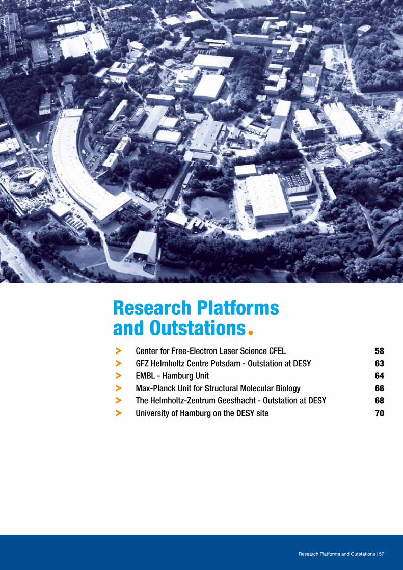
Research platforms and outstationsª
Research Platforms and Outstations | 57
º Center for Free-Electron Laser Science CFEL 58º GFZ Helmholtz Centre Potsdam - Outstation at DESY 63º EMBL - Hamburg Unit 64º Max-Planck Unit for Structural Molecular Biology 66º The Helmholtz-Zentrum Geesthacht - Outstation at DESY 68º University of Hamburg on the DESY site 70
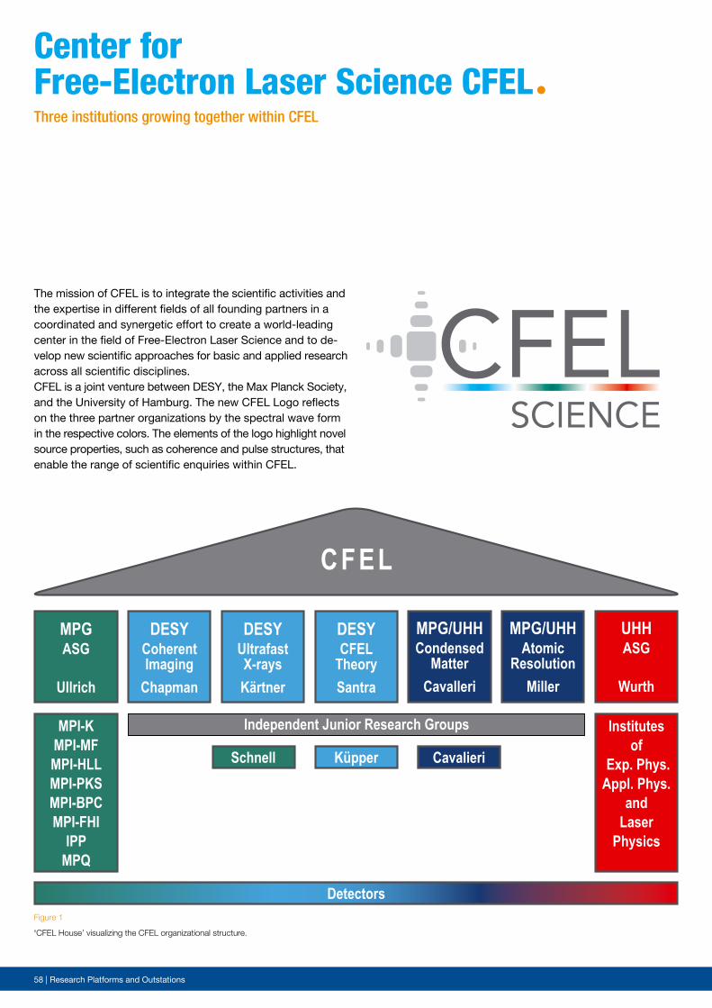
58 | Research Platforms and Outstations
MPG/UHHCondensed
MatterCavalleri
MPG/UHHAtomic
ResolutionMiller
UHHASG
Wurth
CFEL
Cavalieri
DESYCoherentImaging
Chapman
DESYUltrafastX-raysKärtner
DESYCFEL
TheorySantra
Küpper
Independent Junior Research Groups
MPGASG
Ullrich
Schnell
Institutesof
Exp. Phys.Appl. Phys.
andLaser
Physics
MPI-KMPI- MFMPI- HLLMPI- PKSMPI- BPCMPI- FHI
IPPMPQ
DetectorsFigure 1
‘CFEL House’ visualizing the CFEL organizational structure.
The mission of CFEL is to integrate the scientific activities and the expertise in different fields of all founding partners in a coordinated and synergetic effort to create a world-leading center in the field of Free-Electron Laser Science and to de-velop new scientific approaches for basic and applied research across all scientific disciplines. CFEL is a joint venture between DESY, the Max Planck Society, and the University of Hamburg. The new CFEL Logo reflects on the three partner organizations by the spectral wave form in the respective colors. The elements of the logo highlight novel source properties, such as coherence and pulse structures, that enable the range of scientific enquiries within CFEL.
center for Free-electron Laser science cFeLªThree institutions growing together within CFEL
CFELSCIENCE
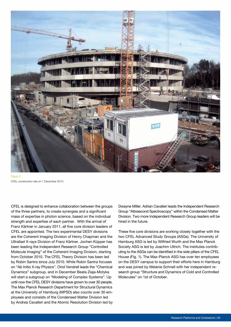
Research Platforms and Outstations | 59
Figure 2
CFEL construction site on 1 December 2010.
CFEL is designed to enhance collaboration between the groups of the three partners, to create synergies and a significant mass of expertise in photon science, based on the individual strength and expertise of each partner. With the arrival of Franz Kärtner in January 2011, all five core division leaders of CFEL are appointed. The two experimental DESY divisions are the Coherent Imaging Division of Henry Chapman and the Ultrafast X-rays Division of Franz Kärtner. Jochen Küpper has been leading the Independent Research Group “Controlled Molecule Imaging” of the Coherent Imaging Division, starting from October 2010. The CFEL Theory Division has been led by Robin Santra since July 2010. While Robin Santra focuses on “Ab Initio X-ray Physics”, Oriol Vendrell leads the “Chemical Dynamics” subgroup, and in December Beata Ziaja-Motyka will start a subgroup on “Modeling of Complex Systems”. Up until now the CFEL DESY divisions have grown to over 30 people. The Max Planck Research Department for Structural Dynamics at the University of Hamburg (MPSD) also counts over 30 em-ployees and consists of the Condensed Matter Division led by Andrea Cavalleri and the Atomic Resolution Division led by
Dwayne Miller. Adrian Cavalieri leads the Independent Research Group “Attosecond Spectroscopy” within the Condensed Matter Division. Two more Independent Research Group leaders will be hired in the future.
These five core divisions are working closely together with the two CFEL Advanced Study Groups (ASGs). The University of Hamburg ASG is led by Wilfried Wurth and the Max Planck Society ASG is led by Joachim Ullrich. The institutes contrib-uting to the ASGs can be identified in the side pillars of the CFEL House (Fig. 1). The Max-Planck ASG has over ten employees on the DESY campus to support their efforts here in Hamburg and was joined by Melanie Schnell with her independent re-search group “Structure and Dynamics of Cold and Controlled Molecules” on 1st of October.
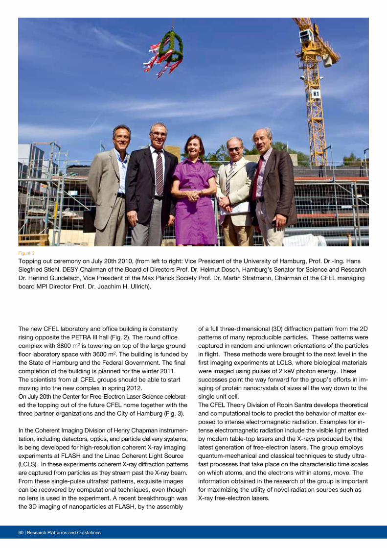
60 | Research Platforms and Outstations
Figure 3
Topping out ceremony on July 20th 2010, (from left to right: Vice President of the University of Hamburg, Prof. Dr.-Ing. Hans Siegfried Stiehl, DESY Chairman of the Board of Directors Prof. Dr. Helmut Dosch, Hamburg’s Senator for Science and Research Dr. Herlind Gundelach, Vice President of the Max Planck Society Prof. Dr. Martin Stratmann, Chairman of the CFEL managing board MPI Director Prof. Dr. Joachim H. Ullrich).
The new CFEL laboratory and office building is constantly rising opposite the PETRA III hall (Fig. 2). The round office complex with 3800 m2 is towering on top of the large ground floor laboratory space with 3600 m2. The building is funded by the State of Hamburg and the Federal Government. The final completion of the building is planned for the winter 2011. The scientists from all CFEL groups should be able to start moving into the new complex in spring 2012.On July 20th the Center for Free-Electron Laser Science celebrat-ed the topping out of the future CFEL home together with the three partner organizations and the City of Hamburg (Fig. 3).
In the Coherent Imaging Division of Henry Chapman instrumen-tation, including detectors, optics, and particle delivery systems, is being developed for high-resolution coherent X-ray imaging experiments at FLASH and the Linac Coherent Light Source (LCLS). In these experiments coherent X-ray diffraction patterns are captured from particles as they stream past the X-ray beam. From these single-pulse ultrafast patterns, exquisite images can be recovered by computational techniques, even though no lens is used in the experiment. A recent breakthrough was the 3D imaging of nanoparticles at FLASH, by the assembly
of a full three-dimensional (3D) diffraction pattern from the 2D patterns of many reproducible particles. These patterns were captured in random and unknown orientations of the particles in flight. These methods were brought to the next level in the first imaging experiments at LCLS, where biological materials were imaged using pulses of 2 keV photon energy. These successes point the way forward for the group’s efforts in im-aging of protein nanocrystals of sizes all the way down to the single unit cell. The CFEL Theory Division of Robin Santra develops theoretical and computational tools to predict the behavior of matter ex-posed to intense electromagnetic radiation. Examples for in-tense electromagnetic radiation include the visible light emitted by modern table-top lasers and the X-rays produced by the latest generation of free-electron lasers. The group employs quantum-mechanical and classical techniques to study ultra-fast processes that take place on the characteristic time scales on which atoms, and the electrons within atoms, move. The information obtained in the research of the group is important for maximizing the utility of novel radiation sources such as X-ray free-electron lasers.
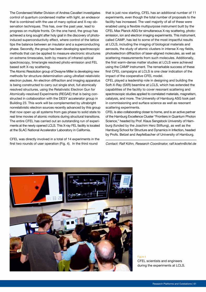
Research Platforms and Outstations | 61
Figure 4
CFEL scientists and engineers during the experiments at LCLS.
Contact: Ralf Köhn, Research Coordinator, [email protected]
The Condensed Matter Division of Andrea Cavalleri investigates control of quantum condensed matter with light, an endeavor that is combined with the use of many optical and X-ray ob-servation techniques. This has, over the past year, lead to progress on multiple fronts. On the one hand, the group has achieved a long sought after holy grail in the discovery of photo-induced superconductivity effect, where control of the lattice tips the balance between an insulator and a superconducting phase. Secondly, the group has been developing spectroscopic methods that can be applied to measure electronic structures on extreme timescales, both by means of infrared optical spectroscopy, time/angle resolved photo-emission and FEL based soft X-ray scattering.The Atomic Resolution group of Dwayne Miller is developing new methods for structure determination using ultrafast relativistic electron pulses. An electron diffraction and imaging apparatus is being constructed to carry out single shot, full atomically resolved structures, using the Relativistic Electron Gun for Atomically-resolved Experiments (REGAE) that is being con-structed in collaboration with the DESY accelerator group in Building 23. This work will be complemented by ultrabright nonrelativistic electron sources recently advanced by this group that now open up all systems from gas phase to solid state to real time movies of atomic motions during structural transitions.The entire CFEL has carried out an outstanding run of experi-ments at the newly opened LCLS. This X-ray FEL facility is located at the SLAC National Accelerator Laboratory in California.
CFEL was directly involved in a total of 14 experiments in the first two rounds of user operation (Fig. 4). In the third round
that is just now starting, CFEL has an additional number of 11 experiments, even though the total number of proposals to the facility has increased. The vast majority of all of these were enabled using a flexible multipurpose instrument built by the CFEL Max Planck ASG for simultaneous X-ray scattering, photo-emission, ion and electron imaging experiments. This instrument, called CAMP, has led to some of the most impactful results at LCLS, including the imaging of biological materials and aerosols, the study of atomic clusters in intense X-ray fields, photoelectron diffraction of laser-aligned molecules, as well as scattering measurements from such molecules. Additionally, the first warm-dense matter studies at LCLS were achieved using the CAMP instrument. The remarkable success of these first CFEL campaigns at LCLS is one clear indication of the impact of the cooperative CFEL model. CFEL played a leadership role in designing and building the Soft-X-Ray (SXR) beamline at LCLS, which has extended the capabilities of the facility to cover resonant scattering and spectroscopic studies applied to correlated materials, magnetism, catalysis, and more. The University of Hamburg ASG took part in commissioning and surface science as well as resonant scattering experiments. CFEL is also collaborating closer to home, and is an active partner of the Hamburg Excellence Cluster “Frontiers in Quantum Photon Science,” headed by Prof. Klaus Sengstock University of Ham-burg (funded by the Joachim Herz Stiftung), as well as the Hamburg School for Structure and Dynamics in Infection, headed by Profs. Betzel and Aepfelbacher of University of Hamburg.
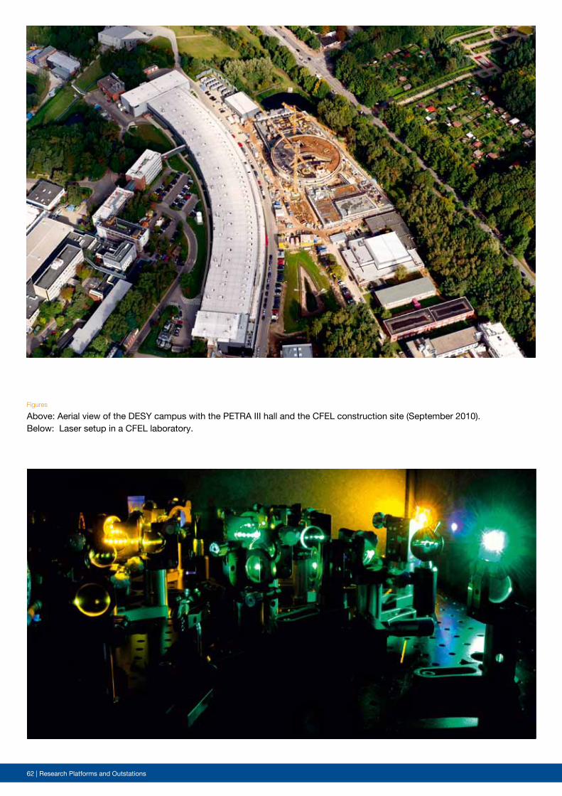
62 | Research Platforms and Outstations
Figures
Above: Aerial view of the DESY campus with the PETRA III hall and the CFEL construction site (September 2010). Below: Laser setup in a CFEL laboratory.
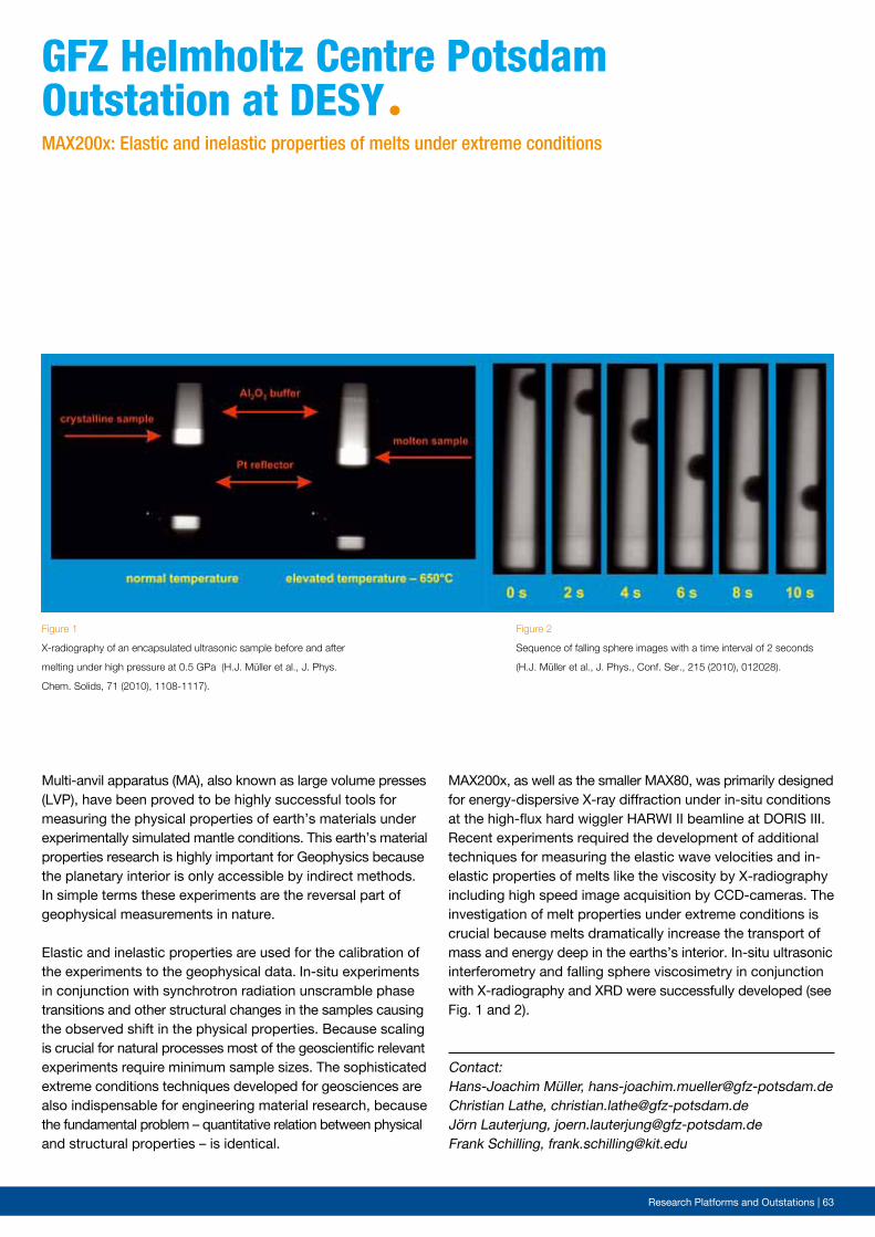
Research Platforms and Outstations | 63
Contact: Hans-Joachim Müller, [email protected] Lathe, [email protected]örn Lauterjung, [email protected] Schilling, [email protected]
Multi-anvil apparatus (MA), also known as large volume presses (LVP), have been proved to be highly successful tools for measuring the physical properties of earth’s materials under experimentally simulated mantle conditions. This earth’s material properties research is highly important for Geophysics because the planetary interior is only accessible by indirect methods. In simple terms these experiments are the reversal part of geophysical measurements in nature.
Elastic and inelastic properties are used for the calibration of the experiments to the geophysical data. In-situ experiments in conjunction with synchrotron radiation unscramble phase transitions and other structural changes in the samples causing the observed shift in the physical properties. Because scaling is crucial for natural processes most of the geoscientific relevant experiments require minimum sample sizes. The sophisticated extreme conditions techniques developed for geosciences are also indispensable for engineering material research, because the fundamental problem – quantitative relation between physical and structural properties – is identical.
GFZ helmholtz centre potsdamoutstation at DesYª
Figure 1
X-radiography of an encapsulated ultrasonic sample before and after
melting under high pressure at 0.5 GPa (H.J. Müller et al., J. Phys.
Chem. Solids, 71 (2010), 1108-1117).
Figure 2
Sequence of falling sphere images with a time interval of 2 seconds
(H.J. Müller et al., J. Phys., Conf. Ser., 215 (2010), 012028).
MAX200x: Elastic and inelastic properties of melts under extreme conditions
MAX200x, as well as the smaller MAX80, was primarily designed for energy-dispersive X-ray diffraction under in-situ conditions at the high-flux hard wiggler HARWI II beamline at DORIS III. Recent experiments required the development of additional techniques for measuring the elastic wave velocities and in-elastic properties of melts like the viscosity by X-radiography including high speed image acquisition by CCD-cameras. The investigation of melt properties under extreme conditions is crucial because melts dramatically increase the transport of mass and energy deep in the earths’s interior. In-situ ultrasonic interferometry and falling sphere viscosimetry in conjunction with X-radiography and XRD were successfully developed (see Fig. 1 and 2).
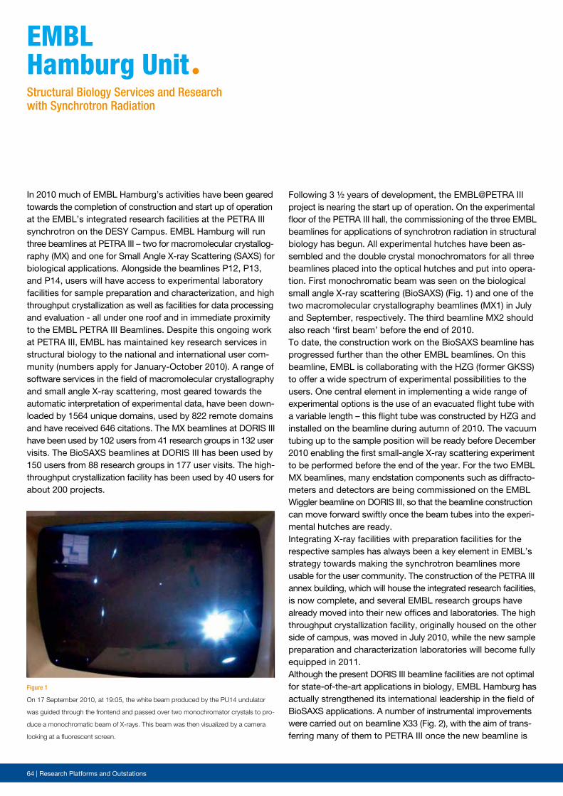
64 | Research Platforms and Outstations
Following 3 ½ years of development, the EMBL@PETRA III project is nearing the start up of operation. On the experimental floor of the PETRA III hall, the commissioning of the three EMBL beamlines for applications of synchrotron radiation in structural biology has begun. All experimental hutches have been as-sembled and the double crystal monochromators for all three beamlines placed into the optical hutches and put into opera-tion. First monochromatic beam was seen on the biological small angle X-ray scattering (BioSAXS) (Fig. 1) and one of the two macromolecular crystallography beamlines (MX1) in July and September, respectively. The third beamline MX2 should also reach ‘first beam’ before the end of 2010.To date, the construction work on the BioSAXS beamline has progressed further than the other EMBL beamlines. On this beamline, EMBL is collaborating with the HZG (former GKSS) to offer a wide spectrum of experimental possibilities to the users. One central element in implementing a wide range of experimental options is the use of an evacuated flight tube with a variable length – this flight tube was constructed by HZG and installed on the beamline during autumn of 2010. The vacuum tubing up to the sample position will be ready before December 2010 enabling the first small-angle X-ray scattering experiment to be performed before the end of the year. For the two EMBL MX beamlines, many endstation components such as diffracto-meters and detectors are being commissioned on the EMBL Wiggler beamline on DORIS III, so that the beamline construction can move forward swiftly once the beam tubes into the experi-mental hutches are ready.Integrating X-ray facilities with preparation facilities for the respective samples has always been a key element in EMBL’s strategy towards making the synchrotron beamlines more usable for the user community. The construction of the PETRA III annex building, which will house the integrated research facilities, is now complete, and several EMBL research groups have already moved into their new offices and laboratories. The high throughput crystallization facility, originally housed on the other side of campus, was moved in July 2010, while the new sample preparation and characterization laboratories will become fully equipped in 2011. Although the present DORIS III beamline facilities are not optimal for state-of-the-art applications in biology, EMBL Hamburg has actually strengthened its international leadership in the field of BioSAXS applications. A number of instrumental improvements were carried out on beamline X33 (Fig. 2), with the aim of trans-ferring many of them to PETRA III once the new beamline is
In 2010 much of EMBL Hamburg’s activities have been geared towards the completion of construction and start up of operation at the EMBL’s integrated research facilities at the PETRA III synchrotron on the DESY Campus. EMBL Hamburg will run three beamlines at PETRA III – two for macromolecular crystallog-raphy (MX) and one for Small Angle X-ray Scattering (SAXS) for biological applications. Alongside the beamlines P12, P13, and P14, users will have access to experimental laboratory facilities for sample preparation and characterization, and high throughput crystallization as well as facilities for data processing and evaluation - all under one roof and in immediate proximity to the EMBL PETRA III Beamlines. Despite this ongoing work at PETRA III, EMBL has maintained key research services in structural biology to the national and international user com-munity (numbers apply for January-October 2010). A range of software services in the field of macromolecular crystallography and small angle X-ray scattering, most geared towards the automatic interpretation of experimental data, have been down-loaded by 1564 unique domains, used by 822 remote domains and have received 646 citations. The MX beamlines at DORIS III have been used by 102 users from 41 research groups in 132 user visits. The BioSAXS beamlines at DORIS III has been used by 150 users from 88 research groups in 177 user visits. The high-throughput crystallization facility has been used by 40 users for about 200 projects.
eMBLhamburg UnitªStructural Biology Services and Research with Synchrotron Radiation
Figure 1
On 17 September 2010, at 19:05, the white beam produced by the PU14 undulator
was guided through the frontend and passed over two monochromator crystals to pro-
duce a monochromatic beam of X-rays. This beam was then visualized by a camera
looking at a fluorescent screen.
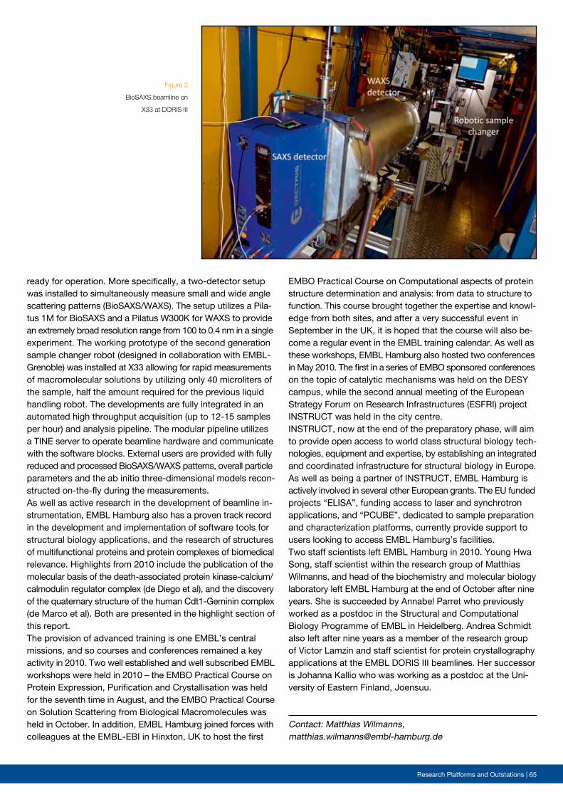
Research Platforms and Outstations | 65
Figure 2
BioSAXS beamline on
X33 at DORIS III
ready for operation. More specifically, a two-detector setup was installed to simultaneously measure small and wide angle scattering patterns (BioSAXS/WAXS). The setup utilizes a Pila-tus 1M for BioSAXS and a Pilatus W300K for WAXS to provide an extremely broad resolution range from 100 to 0.4 nm in a single experiment. The working prototype of the second generation sample changer robot (designed in collaboration with EMBL-Grenoble) was installed at X33 allowing for rapid measurements of macromolecular solutions by utilizing only 40 microliters of the sample, half the amount required for the previous liquid handling robot. The developments are fully integrated in an automated high throughput acquisition (up to 12-15 samples per hour) and analysis pipeline. The modular pipeline utilizes a TINE server to operate beamline hardware and communicate with the software blocks. External users are provided with fully reduced and processed BioSAXS/WAXS patterns, overall particle parameters and the ab initio three-dimensional models recon-structed on-the-fly during the measurements.As well as active research in the development of beamline in-strumentation, EMBL Hamburg also has a proven track record in the development and implementation of software tools for structural biology applications, and the research of structures of multifunctional proteins and protein complexes of biomedical relevance. Highlights from 2010 include the publication of the molecular basis of the death-associated protein kinase-calcium/calmodulin regulator complex (de Diego et al), and the discovery of the quaternary structure of the human Cdt1-Geminin complex (de Marco et al). Both are presented in the highlight section of this report. The provision of advanced training is one EMBL’s central missions, and so courses and conferences remained a key activity in 2010. Two well established and well subscribed EMBL workshops were held in 2010 – the EMBO Practical Course on Protein Expression, Purification and Crystallisation was held for the seventh time in August, and the EMBO Practical Course on Solution Scattering from Biological Macromolecules was held in October. In addition, EMBL Hamburg joined forces with colleagues at the EMBL-EBI in Hinxton, UK to host the first
EMBO Practical Course on Computational aspects of protein structure determination and analysis: from data to structure to function. This course brought together the expertise and knowl-edge from both sites, and after a very successful event in September in the UK, it is hoped that the course will also be-come a regular event in the EMBL training calendar. As well as these workshops, EMBL Hamburg also hosted two conferences in May 2010. The first in a series of EMBO sponsored conferences on the topic of catalytic mechanisms was held on the DESY campus, while the second annual meeting of the European Strategy Forum on Research Infrastructures (ESFRI) project INSTRUCT was held in the city centre. INSTRUCT, now at the end of the preparatory phase, will aim to provide open access to world class structural biology tech-nologies, equipment and expertise, by establishing an integrated and coordinated infrastructure for structural biology in Europe. As well as being a partner of INSTRUCT, EMBL Hamburg is actively involved in several other European grants. The EU funded projects “ELISA”, funding access to laser and synchrotron applications, and “PCUBE”, dedicated to sample preparation and characterization platforms, currently provide support to users looking to access EMBL Hamburg’s facilities. Two staff scientists left EMBL Hamburg in 2010. Young Hwa Song, staff scientist within the research group of Matthias Wilmanns, and head of the biochemistry and molecular biology laboratory left EMBL Hamburg at the end of October after nine years. She is succeeded by Annabel Parret who previously worked as a postdoc in the Structural and Computational Biology Programme of EMBL in Heidelberg. Andrea Schmidt also left after nine years as a member of the research group of Victor Lamzin and staff scientist for protein crystallography applications at the EMBL DORIS III beamlines. Her successor is Johanna Kallio who was working as a postdoc at the Uni-versity of Eastern Finland, Joensuu.
Contact: Matthias Wilmanns, [email protected]
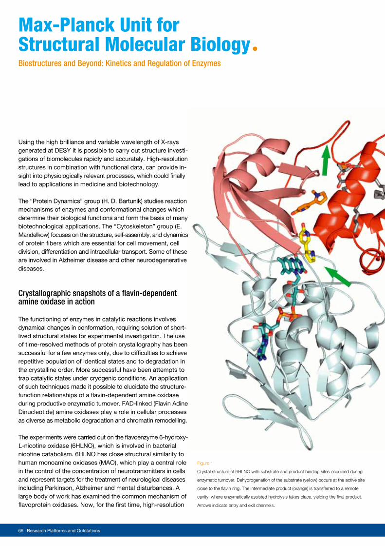
66 | Research Platforms and Outstations
Using the high brilliance and variable wavelength of X-rays generated at DESY it is possible to carry out structure investi-gations of biomolecules rapidly and accurately. High-resolution structures in combination with functional data, can provide in-sight into physiologically relevant processes, which could finally lead to applications in medicine and biotechnology.
The “Protein Dynamics” group (H. D. Bartunik) studies reaction mechanisms of enzymes and conformational changes which determine their biological functions and form the basis of many biotechnological applications. The “Cytoskeleton” group (E. Mandelkow) focuses on the structure, self-assembly, and dynamics of protein fibers which are essential for cell movement, cell division, differentiation and intracellular transport. Some of these are involved in Alzheimer disease and other neurodegenerative diseases.
Crystallographic snapshots of a flavin-dependent amine oxidase in action
The functioning of enzymes in catalytic reactions involves dynamical changes in conformation, requiring solution of short-lived structural states for experimental investigation. The use of time-resolved methods of protein crystallography has been successful for a few enzymes only, due to difficulties to achieve repetitive population of identical states and to degradation in the crystalline order. More successful have been attempts to trap catalytic states under cryogenic conditions. An application of such techniques made it possible to elucidate the structure-function relationships of a flavin-dependent amine oxidase during productive enzymatic turnover. FAD-linked (Flavin Adine Dinucleotide) amine oxidases play a role in cellular processes as diverse as metabolic degradation and chromatin remodelling.
The experiments were carried out on the flavoenzyme 6-hydroxy-L-nicotine oxidase (6HLNO), which is involved in bacterial nicotine catabolism. 6HLNO has close structural similarity to human monoamine oxidases (MAO), which play a central role in the control of the concentration of neurotransmitters in cells and represent targets for the treatment of neurological diseases including Parkinson, Alzheimer and mental disturbances. A large body of work has examined the common mechanism of flavoprotein oxidases. Now, for the first time, high-resolution
Max-planck Unit for structural Molecular BiologyªBiostructures and Beyond: Kinetics and Regulation of Enzymes
Figure 1
Crystal structure of 6HLNO with substrate and product binding sites occupied during
enzymatic turnover. Dehydrogenation of the substrate (yellow) occurs at the active site
close to the flavin ring. The intermediate product (orange) is transferred to a remote
cavity, where enzymatically assisted hydrolysis takes place, yielding the final product.
Arrows indicate entry and exit channels.
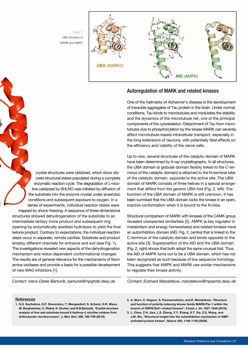
Research Platforms and Outstations | 67
Figure 2
UBA domains of
MARK and AMPK
Contact: Eckhard Mandelkow, [email protected]
References1. G.S. Kachalova, G.P. Bourenkov, T. Mengesdorf, S. Schenk, H.R. Maun, M. Burghammer, C. Riekel, K. Decker, and H.D.Bartunik, “Crystal structure analysis of free and substrate-bound 6-hydroxy-L-nicotine oxidase from Arthrobacter nicotinovorans”, J. Mol. Biol. 396, 785-799 (2010).
Autoregulation of MARK and related kinases
One of the hallmarks of Alzheimer’s disease is the development of insoluble aggregates of Tau protein in the brain. Under normal conditions, Tau binds to microtubules and modulates the stability and the dynamics of the microtubule net, one of the principal components of the cytoskeleton. Detachment of Tau from micro-tubules due to phosphorylation by the kinase MARK can severely affect microtubule-based intracellular transport, especially in the long extensions of neurons, with potentially fatal effects on the efficiency and viability of the nerve cells.
Up to now, several structures of the catalytic domain of MARK have been determined by X-ray crystallography. In all structures, the UBA domain (a globular domain flexibly linked to the C-ter-minus of the catalytic domain) is attached to the N-terminal lobe of the catalytic domain, opposite to the active site. The UBA domain of MARK consists of three helices in a special arrange-ment that differs from the generic UBA fold (Fig. 2, left). The function of the UBA domain of MARK is still unknown. It has been surmised that the UBA domain locks the kinase in an open, inactive conformation when it is bound to the N-lobe.
Structural comparison of MARK with kinases of the CAMK group revealed unexpected similarities [2]. AMPK (a key regulator in metabolism and energy homeostasis) and related kinases have an autoinhibitory domain (AID, Fig. 2, centre) that is linked to the C-terminus of the catalytic domain and binds opposite to the active site [3]. Superposition of the AID and the UBA domain (Fig. 2, right) shows that both adopt the same unusual fold. Thus, the AID of AMPK turns out to be a UBA domain, which has not been recognized as such because of low sequence homology. This suggests that AMPK and MARK use similar mechanisms to regulate their kinase activity.
crystal structures were obtained, which show dis-crete structural states populated during a complete
enzymatic reaction cycle. The degradation of L-nico-tine catalyzed by 6HLNO was initiated by diffusion of
the substrate into the enzyme crystal under anaerobic conditions and subsequent exposure to oxygen. In a series of experiments, individual reaction states were
trapped by shock-freezing. A sequence of three-dimensional structures showed dehydrogenation of the substrate to an intermediate tertiary imine product and subsequent ring opening by enzymatically assisted hydrolysis to yield the final ketone product. Contrary to expectations, the individual reaction steps occur in separate, remote cavities. Substrate and product employ different channels for entrance and exit (see Fig. 1). The investigations revealed new aspects of the dehydrogenation mechanism and redox-dependent conformational changes. The results are of general relevance for the mechanisms of flavin amine oxidases and provide a basis for a possible development of new MAO inhibitors [1].
Contact: Hans-Dieter Bartunik, [email protected]
2. A. Marx, C. Nugoor, S. Panneerselvam, and E. Mandelkow, “Structure and function of polarity-inducing kinase family MARK/Par-1 within the branch of AMPK/Snf1-related kinases”, Faseb J. 24, 1637-1648 (2010).3. L. Chen, Z.H. Jiao, L.S. Zheng, Y.Y. Zhang, S.T. Xie, Z.X. Wang, and J.W. Wu, “Structural insight into the autoinhibition mechanism of AMP- activated protein kinase”, Nature 459, 1146-1149 (2009).
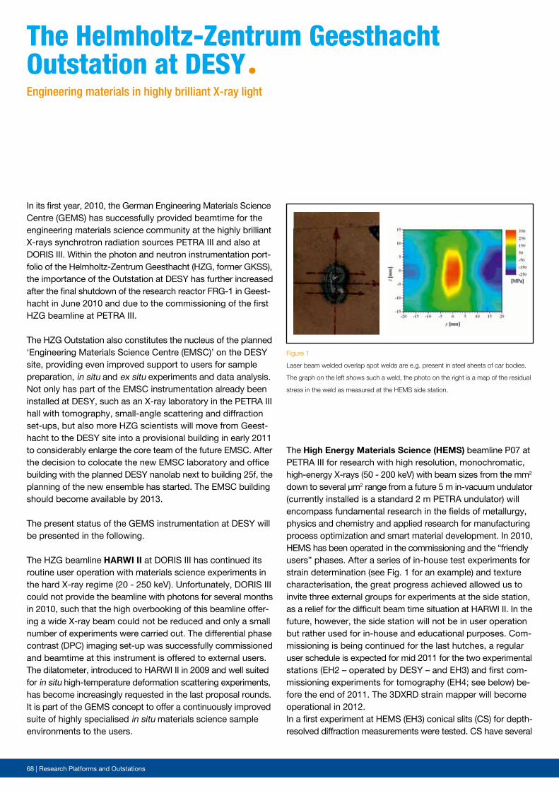
68 | Research Platforms and Outstations
The High Energy Materials Science (HEMS) beamline P07 at PETRA III for research with high resolution, monochromatic, high-energy X-rays (50 - 200 keV) with beam sizes from the mm2 down to several µm2 range from a future 5 m in-vacuum undulator (currently installed is a standard 2 m PETRA undulator) will encompass fundamental research in the fields of metallurgy, physics and chemistry and applied research for manufacturing process optimization and smart material development. In 2010, HEMS has been operated in the commissioning and the “friendly users” phases. After a series of in-house test experiments for strain determination (see Fig. 1 for an example) and texture characterisation, the great progress achieved allowed us to invite three external groups for experiments at the side station, as a relief for the difficult beam time situation at HARWI II. In the future, however, the side station will not be in user operation but rather used for in-house and educational purposes. Com-missioning is being continued for the last hutches, a regular user schedule is expected for mid 2011 for the two experimental stations (EH2 – operated by DESY – and EH3) and first com-missioning experiments for tomography (EH4; see below) be-fore the end of 2011. The 3DXRD strain mapper will become operational in 2012.In a first experiment at HEMS (EH3) conical slits (CS) for depth-resolved diffraction measurements were tested. CS have several
In its first year, 2010, the German Engineering Materials Science Centre (GEMS) has successfully provided beamtime for the engineering materials science community at the highly brilliant X-rays synchrotron radiation sources PETRA III and also at DORIS III. Within the photon and neutron instrumentation port-folio of the Helmholtz-Zentrum Geesthacht (HZG, former GKSS), the importance of the Outstation at DESY has further increased after the final shutdown of the research reactor FRG-1 in Geest-hacht in June 2010 and due to the commissioning of the first HZG beamline at PETRA III.
The HZG Outstation also constitutes the nucleus of the planned ‘Engineering Materials Science Centre (EMSC)’ on the DESY site, providing even improved support to users for sample preparation, in situ and ex situ experiments and data analysis. Not only has part of the EMSC instrumentation already been installed at DESY, such as an X-ray laboratory in the PETRA III hall with tomography, small-angle scattering and diffraction set-ups, but also more HZG scientists will move from Geest-hacht to the DESY site into a provisional building in early 2011 to considerably enlarge the core team of the future EMSC. After the decision to colocate the new EMSC laboratory and office building with the planned DESY nanolab next to building 25f, the planning of the new ensemble has started. The EMSC building should become available by 2013.
The present status of the GEMS instrumentation at DESY will be presented in the following.
The HZG beamline HARWI II at DORIS III has continued its routine user operation with materials science experiments in the hard X-ray regime (20 - 250 keV). Unfortunately, DORIS III could not provide the beamline with photons for several months in 2010, such that the high overbooking of this beamline offer-ing a wide X-ray beam could not be reduced and only a small number of experiments were carried out. The differential phase contrast (DPC) imaging set-up was successfully commissioned and beamtime at this instrument is offered to external users. The dilatometer, introduced to HARWI II in 2009 and well suited for in situ high-temperature deformation scattering experiments, has become increasingly requested in the last proposal rounds. It is part of the GEMS concept to offer a continuously improved suite of highly specialised in situ materials science sample environments to the users.
the helmholtz-Zentrum Geesthacht outstation at DesYªEngineering materials in highly brilliant X-ray light
Figure 1
Laser beam welded overlap spot welds are e.g. present in steel sheets of car bodies.
The graph on the left shows such a weld, the photo on the right is a map of the residual
stress in the weld as measured at the HEMS side station.
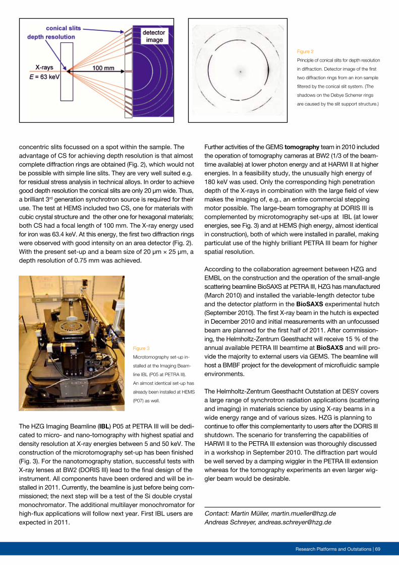
Research Platforms and Outstations | 69
Figure 2
Principle of conical slits for depth resolution
in diffraction. Detector image of the first
two diffraction rings from an iron sample
filtered by the conical slit system. (The
shadows on the Debye Scherrer rings
are caused by the slit support structure.)
Figure 3
Microtomography set-up in-
stalled at the Imaging Beam-
line IBL (P05 at PETRA III).
An almost identical set-up has
already been installed at HEMS
(P07) as well.
Contact: Martin Müller, [email protected] Schreyer, [email protected]
concentric slits focussed on a spot within the sample. The advantage of CS for achieving depth resolution is that almost complete diffraction rings are obtained (Fig. 2), which would not be possible with simple line slits. They are very well suited e.g. for residual stress analysis in technical alloys. In order to achieve good depth resolution the conical slits are only 20 µm wide. Thus, a brilliant 3rd generation synchrotron source is required for their use. The test at HEMS included two CS, one for materials with cubic crystal structure and the other one for hexagonal materials; both CS had a focal length of 100 mm. The X-ray energy used for iron was 63.4 keV. At this energy, the first two diffraction rings were observed with good intensity on an area detector (Fig. 2). With the present set-up and a beam size of 20 µm × 25 µm, a depth resolution of 0.75 mm was achieved.
The HZG Imaging Beamline (IBL) P05 at PETRA III will be dedi-cated to micro- and nano-tomography with highest spatial and density resolution at X-ray energies between 5 and 50 keV. The construction of the microtomography set-up has been finished (Fig. 3). For the nanotomography station, successful tests with X-ray lenses at BW2 (DORIS III) lead to the final design of the instrument. All components have been ordered and will be in-stalled in 2011. Currently, the beamline is just before being com-missioned; the next step will be a test of the Si double crystal monochromator. The additional multilayer monochromator for high-flux applications will follow next year. First IBL users are expected in 2011.
Further activities of the GEMS tomography team in 2010 included the operation of tomography cameras at BW2 (1/3 of the beam-time available) at lower photon energy and at HARWI II at higher energies. In a feasibility study, the unusually high energy of 180 keV was used. Only the corresponding high penetration depth of the X-rays in combination with the large field of view makes the imaging of, e.g., an entire commercial stepping motor possible. The large-beam tomography at DORIS III is complemented by microtomography set-ups at IBL (at lower energies, see Fig. 3) and at HEMS (high energy, almost identical in construction), both of which were installed in parallel, making particulat use of the highly brilliant PETRA III beam for higher spatial resolution.
According to the collaboration agreement between HZG and EMBL on the construction and the operation of the small-angle scattering beamline BioSAXS at PETRA III, HZG has manufactured (March 2010) and installed the variable-length detector tube and the detector platform in the BioSAXS experimental hutch (September 2010). The first X-ray beam in the hutch is expected in December 2010 and initial measurements with an unfocussed beam are planned for the first half of 2011. After commission-ing, the Helmholtz-Zentrum Geesthacht will receive 15 % of the annual available PETRA III beamtime at BioSAXS and will pro-vide the majority to external users via GEMS. The beamline will host a BMBF project for the development of micro fluidic sample environments.
The Helmholtz-Zentrum Geesthacht Outstation at DESY covers a large range of synchrotron radiation applications (scattering and imaging) in materials science by using X-ray beams in a wide energy range and of various sizes. HZG is planning to continue to offer this complementarity to users after the DORIS III shutdown. The scenario for transferring the capabilities of HARWI II to the PETRA III extension was thoroughly discussed in a workshop in September 2010. The diffraction part would be well served by a damping wiggler in the PETRA III extension whereas for the tomography experiments an even larger wig-gler beam would be desirable.
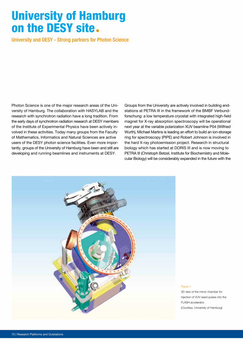
70 | Research Platforms and Outstations
Figure 1
3D view of the mirror chamber for
injection of VUV-seed-pulses into the
FLASH accelerator.
(Courtesy: University of Hamburg)
University of hamburgon the DesY siteªUniversity and DESY - Strong partners for Photon Science
Photon Science is one of the major research areas of the Uni-versity of Hamburg. The collaboration with HASYLAB and the research with synchrotron radiation have a long tradition. From the early days of synchrotron radiation research at DESY members of the Institute of Experimental Physics have been actively in-volved in these activities. Today many groups from the Faculty of Mathematics, Informatics and Natural Sciences are active users of the DESY photon science facilities. Even more impor-tantly, groups of the University of Hamburg have been and still are developing and running beamlines and instruments at DESY.
Groups from the University are actively involved in building end-stations at PETRA III in the framework of the BMBF Verbund-forschung: a low temperature cryostat with integrated high-field magnet for X-ray absorption spectroscopy will be operational next year at the variable polarization XUV beamline P04 (Wilfried Wurth), Michael Martins is leading an effort to build an ion-storage ring for spectroscopy (PIPE) and Robert Johnson is involved in the hard X-ray photoemission project. Research in structural biology which has started at DORIS III and is now moving to PETRA III (Christoph Betzel, Institute for Biochemistry and Mole-cular Biology) will be considerably expanded in the future with the
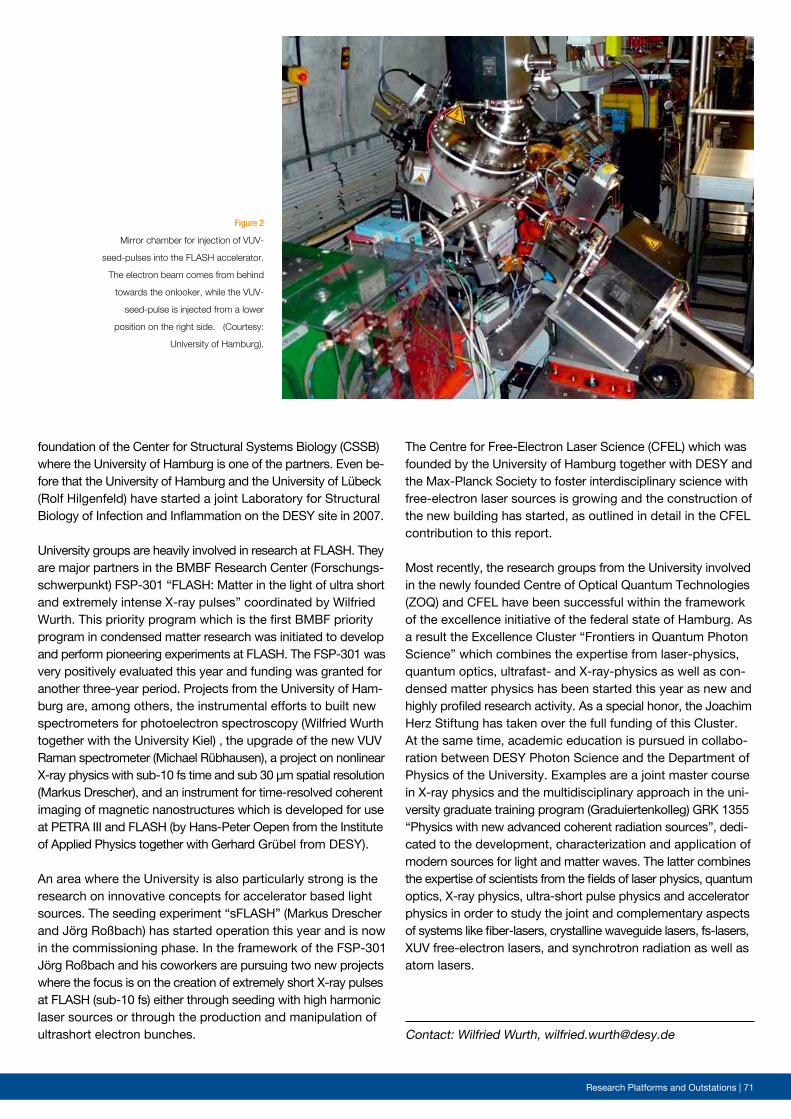
Research Platforms and Outstations | 71
Figure 2
Mirror chamber for injection of VUV-
seed-pulses into the FLASH accelerator.
The electron beam comes from behind
towards the onlooker, while the VUV-
seed-pulse is injected from a lower
position on the right side. (Courtesy:
University of Hamburg).
foundation of the Center for Structural Systems Biology (CSSB) where the University of Hamburg is one of the partners. Even be-fore that the University of Hamburg and the University of Lübeck (Rolf Hilgenfeld) have started a joint Laboratory for Structural Biology of Infection and Inflammation on the DESY site in 2007.
University groups are heavily involved in research at FLASH. They are major partners in the BMBF Research Center (Forschungs-schwerpunkt) FSP-301 “FLASH: Matter in the light of ultra short and extremely intense X-ray pulses” coordinated by Wilfried Wurth. This priority program which is the first BMBF priority program in condensed matter research was initiated to develop and perform pioneering experiments at FLASH. The FSP-301 was very positively evaluated this year and funding was granted for another three-year period. Projects from the University of Ham-burg are, among others, the instrumental efforts to built new spectrometers for photoelectron spectroscopy (Wilfried Wurth together with the University Kiel) , the upgrade of the new VUV Raman spectrometer (Michael Rübhausen), a project on nonlinear X-ray physics with sub-10 fs time and sub 30 µm spatial resolution (Markus Drescher), and an instrument for time-resolved coherent imaging of magnetic nanostructures which is developed for use at PETRA III and FLASH (by Hans-Peter Oepen from the Institute of Applied Physics together with Gerhard Grübel from DESY).
An area where the University is also particularly strong is the research on innovative concepts for accelerator based light sources. The seeding experiment “sFLASH” (Markus Drescher and Jörg Roßbach) has started operation this year and is now in the commissioning phase. In the framework of the FSP-301 Jörg Roßbach and his coworkers are pursuing two new projects where the focus is on the creation of extremely short X-ray pulses at FLASH (sub-10 fs) either through seeding with high harmonic laser sources or through the production and manipulation of ultrashort electron bunches. Contact: Wilfried Wurth, [email protected]
The Centre for Free-Electron Laser Science (CFEL) which was founded by the University of Hamburg together with DESY and the Max-Planck Society to foster interdisciplinary science with free-electron laser sources is growing and the construction of the new building has started, as outlined in detail in the CFEL contribution to this report.
Most recently, the research groups from the University involved in the newly founded Centre of Optical Quantum Technologies (ZOQ) and CFEL have been successful within the framework of the excellence initiative of the federal state of Hamburg. As a result the Excellence Cluster “Frontiers in Quantum Photon Science” which combines the expertise from laser-physics, quantum optics, ultrafast- and X-ray-physics as well as con-densed matter physics has been started this year as new and highly profiled research activity. As a special honor, the Joachim Herz Stiftung has taken over the full funding of this Cluster.At the same time, academic education is pursued in collabo-ration between DESY Photon Science and the Department of Physics of the University. Examples are a joint master course in X-ray physics and the multidisciplinary approach in the uni-versity graduate training program (Graduiertenkolleg) GRK 1355 “Physics with new advanced coherent radiation sources”, dedi-cated to the development, characterization and application of modern sources for light and matter waves. The latter combines the expertise of scientists from the fields of laser physics, quantum optics, X-ray physics, ultra-short pulse physics and accelerator physics in order to study the joint and complementary aspects of systems like fiber-lasers, crystalline waveguide lasers, fs-lasers, XUV free-electron lasers, and synchrotron radiation as well as atom lasers.

72 | Light sources
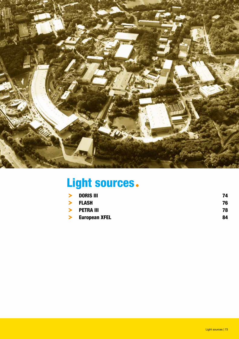
Light sourcesª
Light sources | 73
º DoRis iii 74º FLAsh 76º petRA iii 78º european XFeL 84
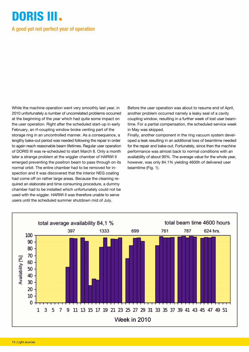
74 | Light sources
Before the user operation was about to resume end of April, another problem occurred namely a leaky seal of a cavity coupling window, resulting in a further week of lost user beam-time. For a partial compensation, the scheduled service week in May was skipped.Finally, another component in the ring vacuum system devel-oped a leak resulting in an additional loss of beamtime needed for the repair and bake-out. Fortunately, since then the machine performance was almost back to normal conditions with an availability of about 90%. The average value for the whole year, however, was only 84.1% yielding 4600h of delivered user beamtime (Fig. 1).
While the machine operation went very smoothly last year, in 2010 unfortunately a number of uncorrelated problems occurred at the beginning of the year which had quite some impact on the user operation. Right after the scheduled start-up in early February, an rf-coupling window broke venting part of the storage ring in an uncontrolled manner. As a consequence, a lengthy bake-out period was needed following the repair in order to again reach reasonable beam lifetimes. Regular user operation of DORIS III was re-scheduled to start March 8. Only a month later a strange problem at the wiggler chamber of HARWI II emerged preventing the positron beam to pass through on its normal orbit. The entire chamber had to be removed for in-spection and it was discovered that the interior NEG coating had come off on rather large areas. Because the cleaning re-quired an elaborate and time consuming procedure, a dummy chamber had to be installed which unfortunately could not be used with the wiggler. HARWI II was therefore unable to serve users until the scheduled summer shutdown mid of July.
DoRis iiiªA good yet not perfect year of operation
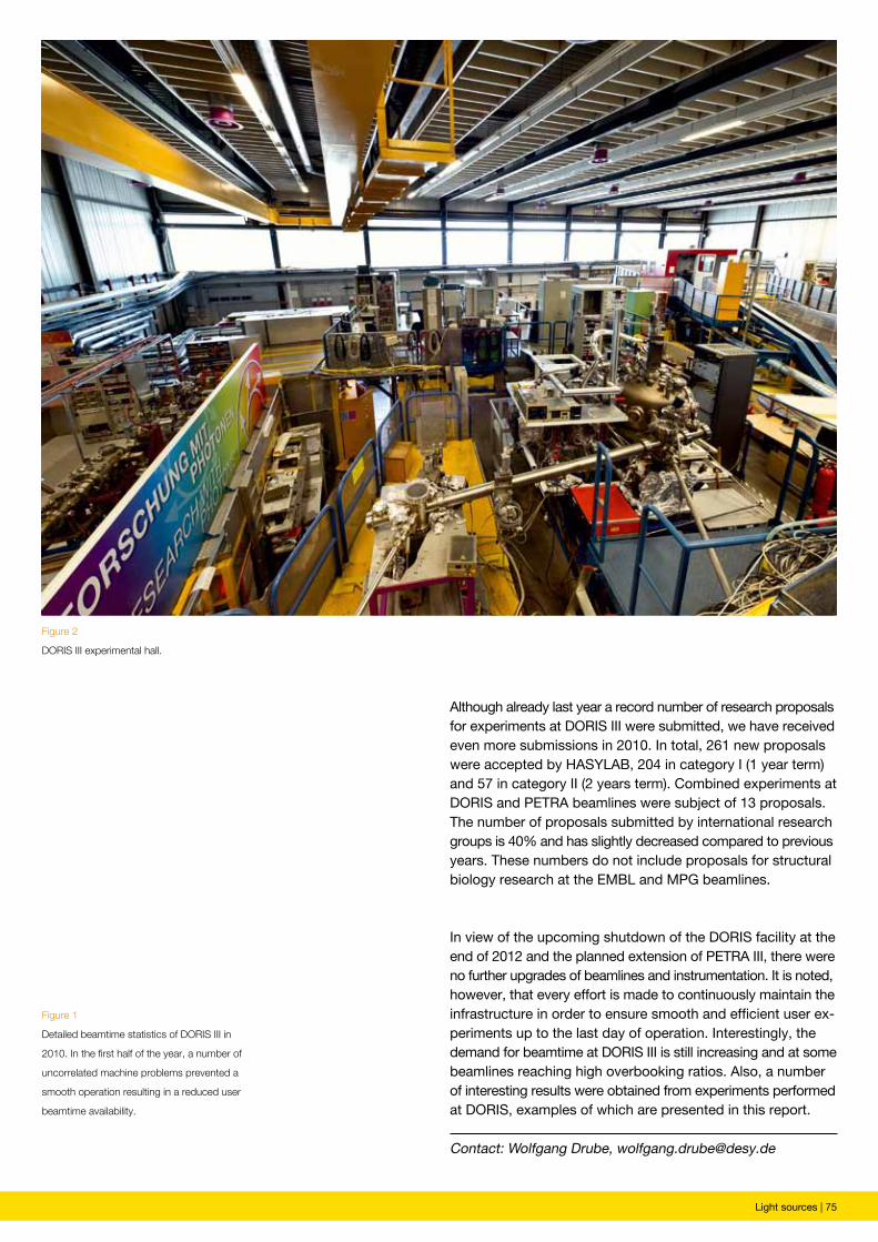
Light sources | 75
Figure 2
DORIS III experimental hall.
Figure 1
Detailed beamtime statistics of DORIS III in
2010. In the first half of the year, a number of
uncorrelated machine problems prevented a
smooth operation resulting in a reduced user
beamtime availability.
Although already last year a record number of research proposals for experiments at DORIS III were submitted, we have received even more submissions in 2010. In total, 261 new proposals were accepted by HASYLAB, 204 in category I (1 year term) and 57 in category II (2 years term). Combined experiments at DORIS and PETRA beamlines were subject of 13 proposals. The number of proposals submitted by international research groups is 40% and has slightly decreased compared to previous years. These numbers do not include proposals for structural biology research at the EMBL and MPG beamlines.
In view of the upcoming shutdown of the DORIS facility at the end of 2012 and the planned extension of PETRA III, there were no further upgrades of beamlines and instrumentation. It is noted, however, that every effort is made to continuously maintain the infrastructure in order to ensure smooth and efficient user ex-periments up to the last day of operation. Interestingly, the demand for beamtime at DORIS III is still increasing and at some beamlines reaching high overbooking ratios. Also, a number of interesting results were obtained from experiments performed at DORIS, examples of which are presented in this report.
Contact: Wolfgang Drube, [email protected]
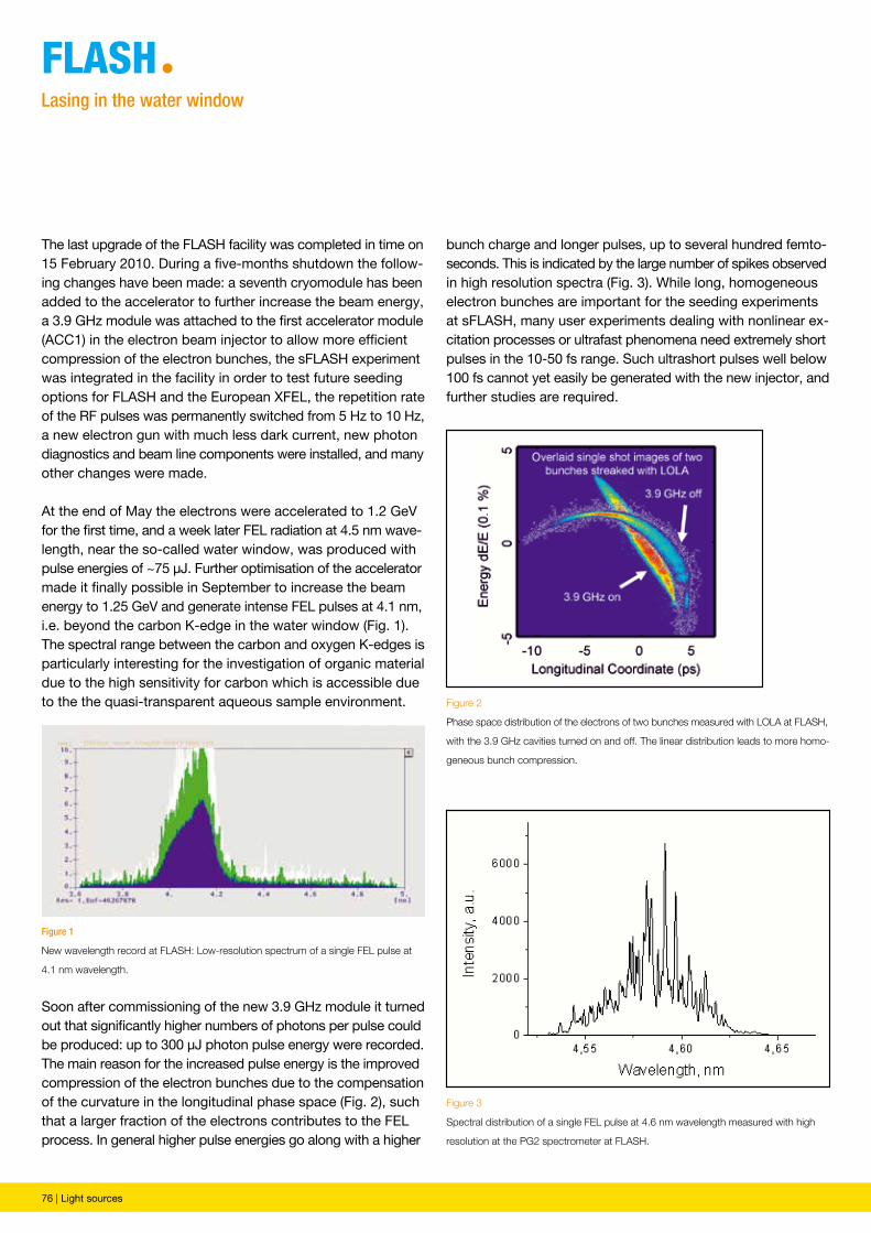
76 | Light sources
FLAshªLasing in the water window
Figure 1
New wavelength record at FLASH: Low-resolution spectrum of a single FEL pulse at
4.1 nm wavelength.
Figure 2
Phase space distribution of the electrons of two bunches measured with LOLA at FLASH,
with the 3.9 GHz cavities turned on and off. The linear distribution leads to more homo-
geneous bunch compression.
Figure 3
Spectral distribution of a single FEL pulse at 4.6 nm wavelength measured with high
resolution at the PG2 spectrometer at FLASH.
The last upgrade of the FLASH facility was completed in time on 15 February 2010. During a five-months shutdown the follow-ing changes have been made: a seventh cryomodule has been added to the accelerator to further increase the beam energy, a 3.9 GHz module was attached to the first accelerator module (ACC1) in the electron beam injector to allow more efficient compression of the electron bunches, the sFLASH experiment was integrated in the facility in order to test future seeding options for FLASH and the European XFEL, the repetition rate of the RF pulses was permanently switched from 5 Hz to 10 Hz, a new electron gun with much less dark current, new photon diagnostics and beam line components were installed, and many other changes were made.
At the end of May the electrons were accelerated to 1.2 GeV for the first time, and a week later FEL radiation at 4.5 nm wave-length, near the so-called water window, was produced with pulse energies of ~75 µJ. Further optimisation of the accelerator made it finally possible in September to increase the beam energy to 1.25 GeV and generate intense FEL pulses at 4.1 nm, i.e. beyond the carbon K-edge in the water window (Fig. 1). The spectral range between the carbon and oxygen K-edges is particularly interesting for the investigation of organic material due to the high sensitivity for carbon which is accessible due to the the quasi-transparent aqueous sample environment.
Soon after commissioning of the new 3.9 GHz module it turned out that significantly higher numbers of photons per pulse could be produced: up to 300 µJ photon pulse energy were recorded. The main reason for the increased pulse energy is the improved compression of the electron bunches due to the compensation of the curvature in the longitudinal phase space (Fig. 2), such that a larger fraction of the electrons contributes to the FEL process. In general higher pulse energies go along with a higher
bunch charge and longer pulses, up to several hundred femto-seconds. This is indicated by the large number of spikes observed in high resolution spectra (Fig. 3). While long, homogeneous electron bunches are important for the seeding experiments at sFLASH, many user experiments dealing with nonlinear ex-citation processes or ultrafast phenomena need extremely short pulses in the 10-50 fs range. Such ultrashort pulses well below 100 fs cannot yet easily be generated with the new injector, and further studies are required.
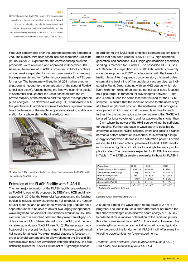
Light sources | 77
Figure 4
Model of the FLASH beamlines: the left part shows the extension of the FLASH facility
planned in the FLASH II project.
Table 1
Expected output parameters for FLASH II.
Figure 5
Schematic layout of the FLASH facility. The electron gun
is on the left, the experimental hall on the right. Behind
the last accelerating module the beam is switched
between the present undulator line (FLASH I), and the
new line (FLASH II). Behind the extraction point, space is
reserved for an additional laser system for seeding.
Contact: Josef Feldhaus, [email protected] (FLASH)Bart Faatz, [email protected] (FLASH II)
First user experiments after the upgrade started on September 2nd. The current, third user period includes more than 350 shifts (12-hours) for 28 experiments, the corresponding scientific proposals were reviewed and approved in December 2009. As usual, beamtime at FLASH is organised in blocks of three or four weeks separated by two or three weeks for changing the experiments and for further improvements of the FEL per-formance. The beamtime will end in fall 2011 when another shutdown is needed for the construction of the second FLASH tunnel (see below). Already during the first two beamtime blocks in September and October the users benefited from the im-proved stability of the machine and the higher average photon pulse energies. The downtime was only 3%, compared to 8% the year before. In addition, improved feedback systems require less interference of the machine operators allowing stable op-eration for a whole shift without readjustment.
Extension of the FLASH Facility with FLASH IIThe next major extension of the FLASH facility, also referred to as FLASH II, was jointly proposed by DESY and HZB and finally approved in 2010 by the Helmholtz Association and the funding bodies. It includes a new experimental hall to double the number of user stations, and an additional variable-gap undulator in a separate tunnel to be able to deliver two largely independent wavelengths to two different user stations simultaneously. The electron beam is switched between the present fixed-gap un-dulator line of FLASH (here referred to as FLASH I) and the new variable gap undulator FLASH II (see Fig. 5). The necessary modi-fication of the present facility is minor. In the new experimental hall space for at least five experimental stations is foreseen. In order to avoid damage and to allow reflecting the 3rd and 5th harmonic down to 0.8 nm wavelength with high efficiency, the first deflecting mirrors for FLASH II will be set at 1° grazing incidence.
In addition to the SASE (self-amplified spontaneous emission) mode that has been used in FLASH I, HHG (high harmonic generation) and cascaded HGHG (high-gain harmonic generation) seeding is foreseen for FLASH II. The cascaded HGHG uses a Ti:Sa laser at a repetition rate of 100 kHz, which is currently under development at DESY in collaboration with the Helmholtz Institut Jena. After frequency up-conversion, this seed pulse enters at the beginning of the undulator vacuum pipe, as indi-cated in Fig. 5. Direct seeding with an HHG source, which de-livers high harmonics of an intense optical laser pulse focused on a gas target, is foreseen for wavelengths between 10 nm and 40 nm. It uses the same laser that is used for the HGHG scheme. To ensure that the radiation source for the users stays at a fixed longitudinal position, the upstream undulator gaps are opened, which means that the seed laser has to reach further into the vacuum pipe at longer wavelengths. SASE will be used for long wavelengths and for wavelengths shorter than ~10 nm where the power of the HHG source will not be sufficient for seeding. Further decrease in wavelength is possible by employing a classical HGHG scheme, where one goes to a higher harmonic before saturation is reached, thus avoiding a large energy spread which decreases the saturation power. For this reason, the HHG seed enters upstream of the first HGHG radiator (not shown in Fig. 5), which allows for a single frequency multi-plication step. The parameters expected for FLASH II are shown in Table 1. The SASE parameters are similar to those for FLASH I.
A study to extend the wavelength range down to 2 nm is in progress. The idea is to use a short afterburner optimized for this short wavelength at an electron beam energy of 1.25 GeV. In order to allow a variable polarization of the radiation pulses, this afterburner would be an APPLE III undulator. However, this wavelength can only be reached at reduced power, typically a few percent of the fundamental. FLASH II will offer many in-teresting opportunities for future experiments.
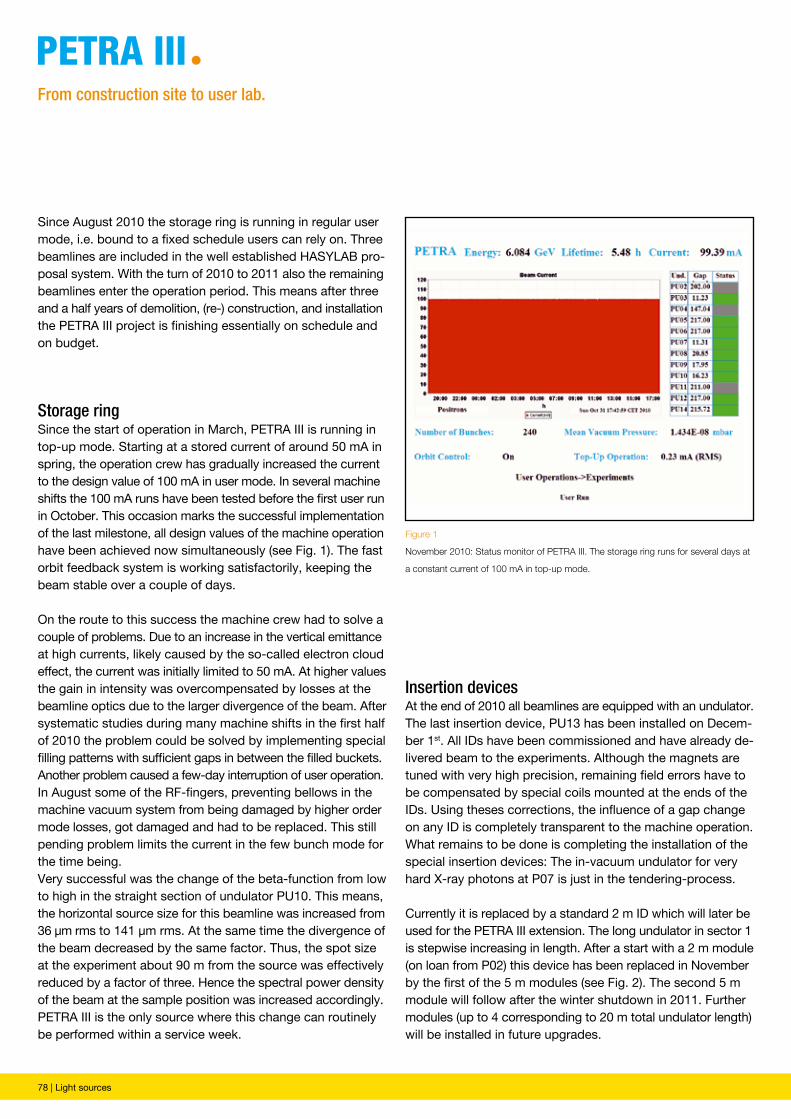
78 | Light sources
Since August 2010 the storage ring is running in regular user mode, i.e. bound to a fixed schedule users can rely on. Three beamlines are included in the well established HASYLAB pro-posal system. With the turn of 2010 to 2011 also the remaining beamlines enter the operation period. This means after three and a half years of demolition, (re-) construction, and installation the PETRA III project is finishing essentially on schedule and on budget.
Storage ringSince the start of operation in March, PETRA III is running in top-up mode. Starting at a stored current of around 50 mA in spring, the operation crew has gradually increased the current to the design value of 100 mA in user mode. In several machine shifts the 100 mA runs have been tested before the first user run in October. This occasion marks the successful implementation of the last milestone, all design values of the machine operation have been achieved now simultaneously (see Fig. 1). The fast orbit feedback system is working satisfactorily, keeping the beam stable over a couple of days.
On the route to this success the machine crew had to solve a couple of problems. Due to an increase in the vertical emittance at high currents, likely caused by the so-called electron cloud effect, the current was initially limited to 50 mA. At higher values the gain in intensity was overcompensated by losses at the beamline optics due to the larger divergence of the beam. After systematic studies during many machine shifts in the first half of 2010 the problem could be solved by implementing special filling patterns with sufficient gaps in between the filled buckets.Another problem caused a few-day interruption of user operation. In August some of the RF-fingers, preventing bellows in the machine vacuum system from being damaged by higher order mode losses, got damaged and had to be replaced. This still pending problem limits the current in the few bunch mode for the time being.Very successful was the change of the beta-function from low to high in the straight section of undulator PU10. This means, the horizontal source size for this beamline was increased from 36 µm rms to 141 µm rms. At the same time the divergence of the beam decreased by the same factor. Thus, the spot size at the experiment about 90 m from the source was effectively reduced by a factor of three. Hence the spectral power density of the beam at the sample position was increased accordingly. PETRA III is the only source where this change can routinely be performed within a service week.
petRA iiiªFrom construction site to user lab.
Insertion devicesAt the end of 2010 all beamlines are equipped with an undulator. The last insertion device, PU13 has been installed on Decem-ber 1st. All IDs have been commissioned and have already de-livered beam to the experiments. Although the magnets are tuned with very high precision, remaining field errors have to be compensated by special coils mounted at the ends of the IDs. Using theses corrections, the influence of a gap change on any ID is completely transparent to the machine operation.What remains to be done is completing the installation of the special insertion devices: The in-vacuum undulator for very hard X-ray photons at P07 is just in the tendering-process.
Currently it is replaced by a standard 2 m ID which will later be used for the PETRA III extension. The long undulator in sector 1 is stepwise increasing in length. After a start with a 2 m module (on loan from P02) this device has been replaced in November by the first of the 5 m modules (see Fig. 2). The second 5 m module will follow after the winter shutdown in 2011. Further modules (up to 4 corresponding to 20 m total undulator length) will be installed in future upgrades.
Figure 1
November 2010: Status monitor of PETRA III. The storage ring runs for several days at
a constant current of 100 mA in top-up mode.
Light sources | 79
Figure 3
A sputter chamber mounted at beamline P03 for in-situ studies of deposition proc-
esses (in collaboration with the team of P01)
Figure 2
The first 5 m undulator module being installed at beamline P01 (November 2010).
Beamlines and experimentsAfter commissioning of the experiments - partly together with ‘friendly’ users - in the first half of the year, three beamlines (P08, P09, and P10) now serve scheduled users. In total, nine beamlines have started operation, the remaining five will get beam in the remaining weeks of this year.
All crystal monochromators are installed and most of them are operating. The devices that have already been commissioned show a reflectivity very close to the theoretical values. The same holds true for the X-ray mirrors that have been installed at P03, P09, and P10. As expected, even very small misalignments and instabilities in the sub-100 nano-radian range show clear effects on the beam at the experiments. Very careful optimization of the experiments is mandatory. In particular all focussing optics implemented so far show the advantage of the superior source quality of PETRA III.
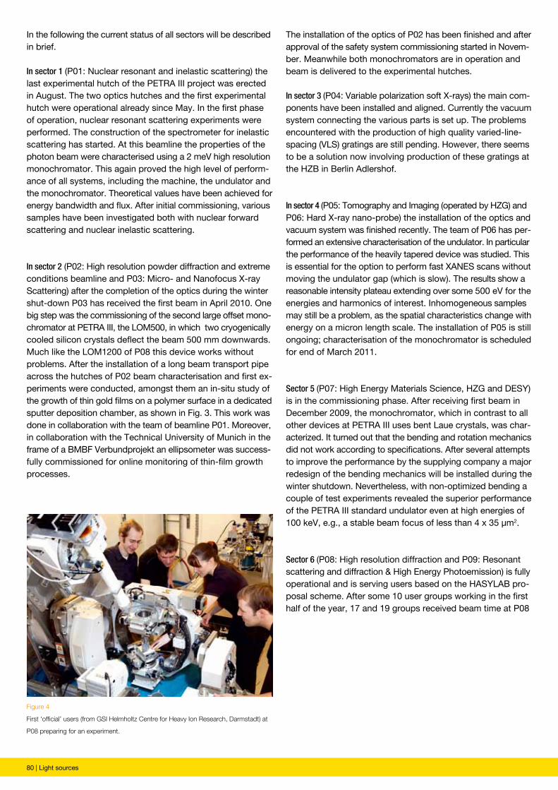
80 | Light sources
The installation of the optics of P02 has been finished and after approval of the safety system commissioning started in Novem-ber. Meanwhile both monochromators are in operation and beam is delivered to the experimental hutches.
In sector 3 (P04: Variable polarization soft X-rays) the main com-ponents have been installed and aligned. Currently the vacuum system connecting the various parts is set up. The problems encountered with the production of high quality varied-line-spacing (VLS) gratings are still pending. However, there seems to be a solution now involving production of these gratings at the HZB in Berlin Adlershof.
In sector 4 (P05: Tomography and Imaging (operated by HZG) and P06: Hard X-ray nano-probe) the installation of the optics and vacuum system was finished recently. The team of P06 has per-formed an extensive characterisation of the undulator. In particular the performance of the heavily tapered device was studied. This is essential for the option to perform fast XANES scans without moving the undulator gap (which is slow). The results show a reasonable intensity plateau extending over some 500 eV for the energies and harmonics of interest. Inhomogeneous samples may still be a problem, as the spatial characteristics change with energy on a micron length scale. The installation of P05 is still ongoing; characterisation of the monochromator is scheduled for end of March 2011.
Sector 5 (P07: High Energy Materials Science, HZG and DESY) is in the commissioning phase. After receiving first beam in December 2009, the monochromator, which in contrast to all other devices at PETRA III uses bent Laue crystals, was char-acterized. It turned out that the bending and rotation mechanics did not work according to specifications. After several attempts to improve the performance by the supplying company a major redesign of the bending mechanics will be installed during the winter shutdown. Nevertheless, with non-optimized bending a couple of test experiments revealed the superior performance of the PETRA III standard undulator even at high energies of 100 keV, e.g., a stable beam focus of less than 4 x 35 µm2.
Sector 6 (P08: High resolution diffraction and P09: Resonant scattering and diffraction & High Energy Photoemission) is fully operational and is serving users based on the HASYLAB pro-posal scheme. After some 10 user groups working in the first half of the year, 17 and 19 groups received beam time at P08
In the following the current status of all sectors will be described in brief.
In sector 1 (P01: Nuclear resonant and inelastic scattering) the last experimental hutch of the PETRA III project was erected in August. The two optics hutches and the first experimental hutch were operational already since May. In the first phase of operation, nuclear resonant scattering experiments were performed. The construction of the spectrometer for inelastic scattering has started. At this beamline the properties of the photon beam were characterised using a 2 meV high resolution monochromator. This again proved the high level of perform-ance of all systems, including the machine, the undulator and the monochromator. Theoretical values have been achieved for energy bandwidth and flux. After initial commissioning, various samples have been investigated both with nuclear forward scattering and nuclear inelastic scattering.
In sector 2 (P02: High resolution powder diffraction and extreme conditions beamline and P03: Micro- and Nanofocus X-ray Scattering) after the completion of the optics during the winter shut-down P03 has received the first beam in April 2010. One big step was the commissioning of the second large offset mono-chromator at PETRA III, the LOM500, in which two cryogenically cooled silicon crystals deflect the beam 500 mm downwards. Much like the LOM1200 of P08 this device works without problems. After the installation of a long beam transport pipe across the hutches of P02 beam characterisation and first ex-periments were conducted, amongst them an in-situ study of the growth of thin gold films on a polymer surface in a dedicated sputter deposition chamber, as shown in Fig. 3. This work was done in collaboration with the team of beamline P01. Moreover, in collaboration with the Technical University of Munich in the frame of a BMBF Verbundprojekt an ellipsometer was success-fully commissioned for online monitoring of thin-film growth processes.
Figure 4
First ‘official’ users (from GSI Helmholtz Centre for Heavy Ion Research, Darmstadt) at
P08 preparing for an experiment.
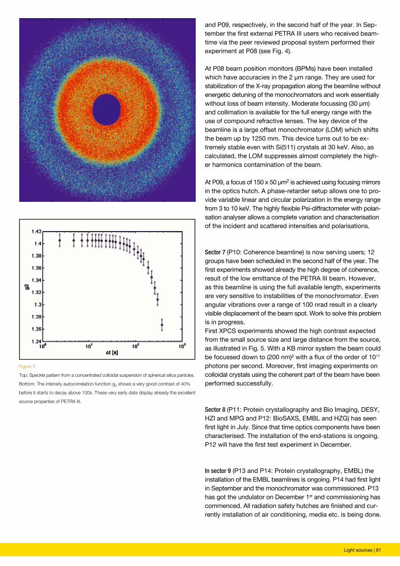
Light sources | 81
and P09, respectively, in the second half of the year. In Sep-tember the first external PETRA III users who received beam-time via the peer reviewed proposal system performed their experiment at P08 (see Fig. 4).
At P08 beam position monitors (BPMs) have been installed which have accuracies in the 2 µm range. They are used for stabilization of the X-ray propagation along the beamline without energetic detuning of the monochromators and work essentially without loss of beam intensity. Moderate focussing (30 µm) and collimation is available for the full energy range with the use of compound refractive lenses. The key device of the beamline is a large offset monochromator (LOM) which shifts the beam up by 1250 mm. This device turns out to be ex-tremely stable even with Si(511) crystals at 30 keV. Also, as calculated, the LOM suppresses almost completely the high-er harmonics contamination of the beam.
At P09, a focus of 150 x 50 µm2 is achieved using focusing mirrors in the optics hutch. A phase-retarder setup allows one to pro-vide variable linear and circular polarization in the energy range from 3 to 10 keV. The highly flexible Psi-diffractometer with polari-sation analyser allows a complete variation and characterisation of the incident and scattered intensities and polarisations.
Sector 7 (P10: Coherence beamline) is now serving users; 12 groups have been scheduled in the second half of the year. The first experiments showed already the high degree of coherence, result of the low emittance of the PETRA III beam. However, as this beamline is using the full available length, experiments are very sensitive to instabilities of the monochromator. Even angular vibrations over a range of 100 nrad result in a clearly visible displacement of the beam spot. Work to solve this problem is in progress.First XPCS experiments showed the high contrast expected from the small source size and large distance from the source, as illustrated in Fig. 5. With a KB mirror system the beam could be focussed down to (200 nm)² with a flux of the order of 1011 photons per second. Moreover, first imaging experiments on colloidal crystals using the coherent part of the beam have been performed successfully.
Sector 8 (P11: Protein crystallography and Bio Imaging, DESY, HZI and MPG and P12: BioSAXS, EMBL and HZG) has seen first light in July. Since that time optics components have been characterised. The installation of the end-stations is ongoing. P12 will have the first test experiment in December.
In sector 9 (P13 and P14: Protein crystallography, EMBL) the installation of the EMBL beamlines is ongoing. P14 had first light in September and the monochromator was commissioned. P13 has got the undulator on December 1st and commissioning has commenced. All radiation safety hutches are finished and cur-rently installation of air conditioning, media etc. is being done.
Figure 5
Top: Speckle pattern from a concentrated colloidal suspension of spherical silica particles.
Bottom: The intensity autocorrelation function g2 shows a very good contrast of 40%
before it starts to decay above 100s. These very early data display already the excellent
source properties of PETRA III.
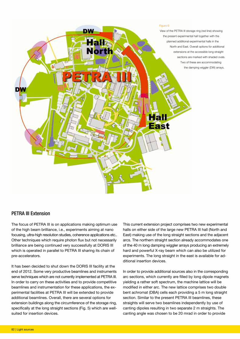
82 | Light sources
PETRA III Extension
The focus of PETRA III is on applications making optimum use of the high beam brilliance, i.e., experiments aiming at nano focusing, ultra-high resolution studies, coherence applications etc.. Other techniques which require photon flux but not necessarily brilliance are being continued very successfully at DORIS III which is operated in parallel to PETRA III sharing its chain of pre-accelerators.
It has been decided to shut down the DORIS III facility at the end of 2012. Some very productive beamlines and instruments serve techniques which are not currently implemented at PETRA III. In order to carry on these activities and to provide competitive beamlines and instrumentation for these applications, the ex-perimental facilities at PETRA III will be extended to provide additional beamlines. Overall, there are several options for extension buildings along the circumference of the storage ring, specifically at the long straight sections (Fig. 5) which are well-suited for insertion devices.
This current extension project comprises two new experimental halls on either side of the large new PETRA III hall (North and East) making use of the long straight sections and the adjacent arcs. The northern straight section already accommodates one of the 40 m long damping wiggler arrays producing an extremely hard and powerful X-ray beam which can also be utilized for experiments. The long straight in the east is available for ad-ditional insertion devices.
In order to provide additional sources also in the corresponding arc sections, which currently are filled by long dipole magnets yielding a rather soft spectrum, the machine lattice will be modified in either arc. The new lattice comprises two double bent achromat (DBA) cells each providing a 5 m long straight section. Similar to the present PETRA III beamlines, these straights will serve two beamlines independently by use of canting dipoles resulting in two separate 2 m straights. The canting angle was chosen to be 20 mrad in order to provide
Figure 6
View of the PETRA III storage ring (red line) showing
the present experimental hall together with the
planned additional experimental halls in the
North and East. Overall options for additional
extensions at the accessible long straight
sections are marked with shaded ovals.
Two of these are accommodating
the damping wiggler (DW) arrays.
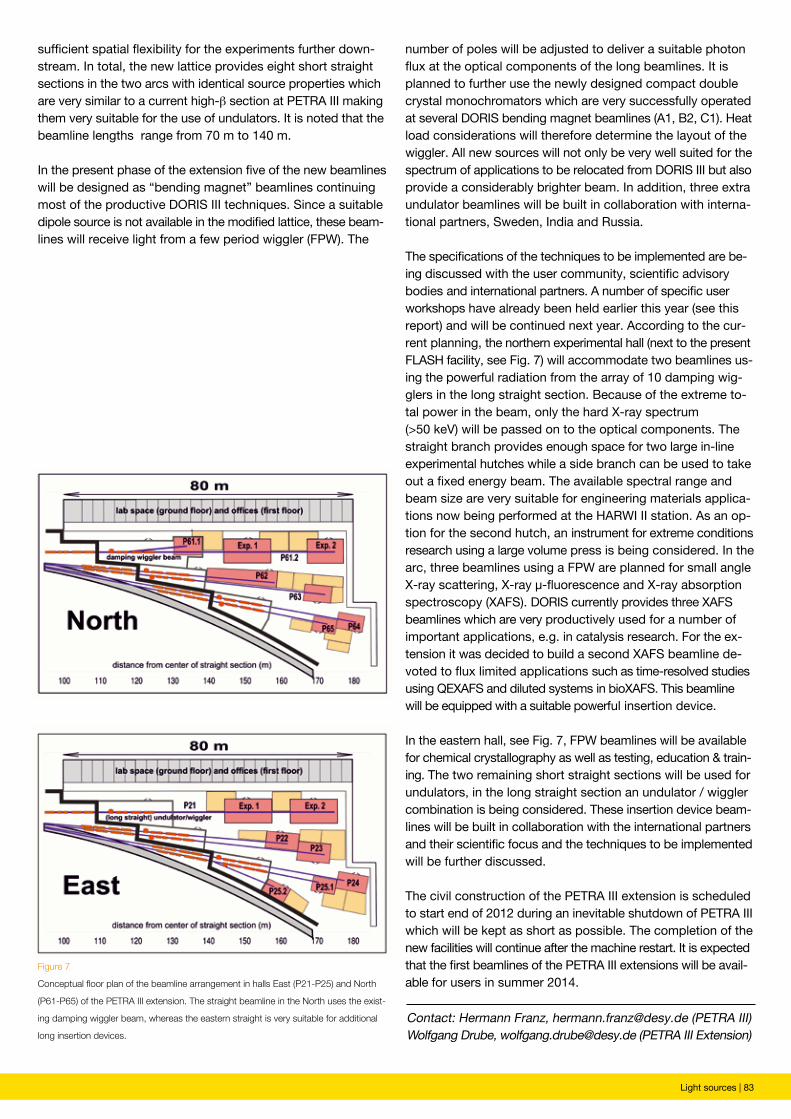
Light sources | 83
Contact: Hermann Franz, [email protected] (PETRA III)Wolfgang Drube, [email protected] (PETRA III Extension)
Figure 7
Conceptual floor plan of the beamline arrangement in halls East (P21-P25) and North
(P61-P65) of the PETRA III extension. The straight beamline in the North uses the exist-
ing damping wiggler beam, whereas the eastern straight is very suitable for additional
long insertion devices.
sufficient spatial flexibility for the experiments further down-stream. In total, the new lattice provides eight short straight sections in the two arcs with identical source properties which are very similar to a current high-β section at PETRA III making them very suitable for the use of undulators. It is noted that the beamline lengths range from 70 m to 140 m.
In the present phase of the extension five of the new beamlines will be designed as “bending magnet” beamlines continuing most of the productive DORIS III techniques. Since a suitable dipole source is not available in the modified lattice, these beam-lines will receive light from a few period wiggler (FPW). The
number of poles will be adjusted to deliver a suitable photon flux at the optical components of the long beamlines. It is planned to further use the newly designed compact double crystal monochromators which are very successfully operated at several DORIS bending magnet beamlines (A1, B2, C1). Heat load considerations will therefore determine the layout of the wiggler. All new sources will not only be very well suited for the spectrum of applications to be relocated from DORIS III but also provide a considerably brighter beam. In addition, three extra undulator beamlines will be built in collaboration with interna-tional partners, Sweden, India and Russia.
The specifications of the techniques to be implemented are be-ing discussed with the user community, scientific advisory bodies and international partners. A number of specific user workshops have already been held earlier this year (see this report) and will be continued next year. According to the cur-rent planning, the northern experimental hall (next to the present FLASH facility, see Fig. 7) will accommodate two beamlines us-ing the powerful radiation from the array of 10 damping wig-glers in the long straight section. Because of the extreme to-tal power in the beam, only the hard X-ray spectrum (>50 keV) will be passed on to the optical components. The straight branch provides enough space for two large in-line experimental hutches while a side branch can be used to take out a fixed energy beam. The available spectral range and beam size are very suitable for engineering materials applica-tions now being performed at the HARWI II station. As an op-tion for the second hutch, an instrument for extreme conditions research using a large volume press is being considered. In the arc, three beamlines using a FPW are planned for small angle X-ray scattering, X-ray μ-fluorescence and X-ray absorption spectroscopy (XAFS). DORIS currently provides three XAFS beamlines which are very productively used for a number of important applications, e.g. in catalysis research. For the ex-tension it was decided to build a second XAFS beamline de-voted to flux limited applications such as time-resolved studies using QEXAFS and diluted systems in bioXAFS. This beamline will be equipped with a suitable powerful insertion device.
In the eastern hall, see Fig. 7, FPW beamlines will be available for chemical crystallography as well as testing, education & train-ing. The two remaining short straight sections will be used for undulators, in the long straight section an undulator / wiggler combination is being considered. These insertion device beam-lines will be built in collaboration with the international partners and their scientific focus and the techniques to be implemented will be further discussed.
The civil construction of the PETRA III extension is scheduled to start end of 2012 during an inevitable shutdown of PETRA III which will be kept as short as possible. The completion of the new facilities will continue after the machine restart. It is expected that the first beamlines of the PETRA III extensions will be avail-able for users in summer 2014.
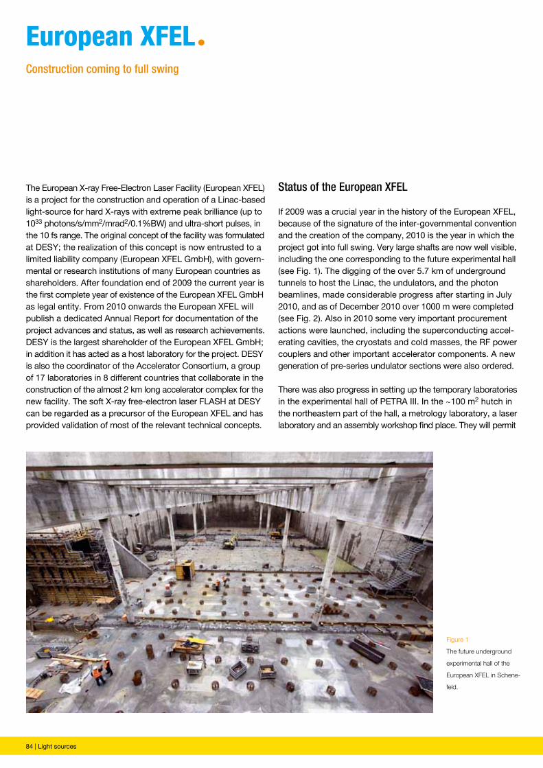
84 | Light sources
The European X-ray Free-Electron Laser Facility (European XFEL) is a project for the construction and operation of a Linac-based light-source for hard X-rays with extreme peak brilliance (up to 1033 photons/s/mm2/mrad2/0.1%BW) and ultra-short pulses, in the 10 fs range. The original concept of the facility was formulated at DESY; the realization of this concept is now entrusted to a limited liability company (European XFEL GmbH), with govern-mental or research institutions of many European countries as shareholders. After foundation end of 2009 the current year is the first complete year of existence of the European XFEL GmbH as legal entity. From 2010 onwards the European XFEL will publish a dedicated Annual Report for documentation of the project advances and status, as well as research achievements. DESY is the largest shareholder of the European XFEL GmbH; in addition it has acted as a host laboratory for the project. DESY is also the coordinator of the Accelerator Consortium, a group of 17 laboratories in 8 different countries that collaborate in the construction of the almost 2 km long accelerator complex for the new facility. The soft X-ray free-electron laser FLASH at DESY can be regarded as a precursor of the European XFEL and has provided validation of most of the relevant technical concepts.
european XFeLªConstruction coming to full swing
Figure 1
The future underground
experimental hall of the
European XFEL in Schene-
feld.
Status of the European XFEL
If 2009 was a crucial year in the history of the European XFEL, because of the signature of the inter-governmental convention and the creation of the company, 2010 is the year in which the project got into full swing. Very large shafts are now well visible, including the one corresponding to the future experimental hall (see Fig. 1). The digging of the over 5.7 km of underground tunnels to host the Linac, the undulators, and the photon beamlines, made considerable progress after starting in July 2010, and as of December 2010 over 1000 m were completed (see Fig. 2). Also in 2010 some very important procurement actions were launched, including the superconducting accel-erating cavities, the cryostats and cold masses, the RF power couplers and other important accelerator components. A new generation of pre-series undulator sections were also ordered.
There was also progress in setting up the temporary laboratories in the experimental hall of PETRA III. In the ~100 m2 hutch in the northeastern part of the hall, a metrology laboratory, a laser laboratory and an assembly workshop find place. They will permit
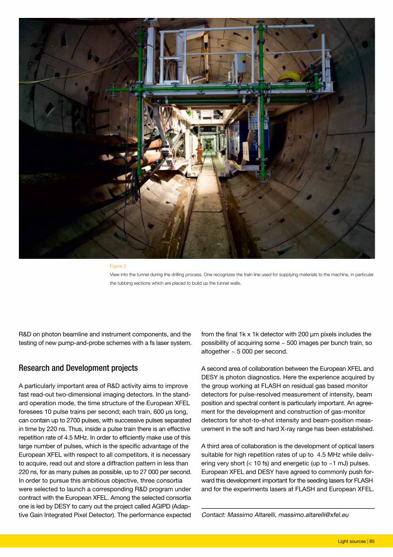
Light sources | 85
Figure 2
View into the tunnel during the drilling process. One recognizes the train line used for supplying materials to the machine, in particular
the tubbing sections which are placed to build up the tunnel walls.
R&D on photon beamline and instrument components, and the testing of new pump-and-probe schemes with a fs laser system.
Research and Development projects
A particularly important area of R&D activity aims to improve fast read-out two-dimensional imaging detectors. In the stand-ard operation mode, the time structure of the European XFEL foresees 10 pulse trains per second; each train, 600 µs long, can contain up to 2700 pulses, with successive pulses separated in time by 220 ns. Thus, inside a pulse train there is an effective repetition rate of 4.5 MHz. In order to efficiently make use of this large number of pulses, which is the specific advantage of the European XFEL with respect to all competitors, it is necessary to acquire, read out and store a diffraction pattern in less than 220 ns, for as many pulses as possible, up to 27 000 per second. In order to pursue this ambitious objective, three consortia were selected to launch a corresponding R&D program under contract with the European XFEL. Among the selected consortia one is led by DESY to carry out the project called AGIPD (Adap-tive Gain Integrated Pixel Detector). The performance expected
from the final 1k x 1k detector with 200 µm pixels includes the possibility of acquiring some ~ 500 images per bunch train, so altogether ~ 5 000 per second.
A second area of collaboration between the European XFEL and DESY is photon diagnostics. Here the experience acquired by the group working at FLASH on residual gas based monitor detectors for pulse-resolved measurement of intensity, beam position and spectral content is particularly important. An agree-ment for the development and construction of gas-monitor detectors for shot-to-shot intensity and beam-position meas-urement in the soft and hard X-ray range has been established.
A third area of collaboration is the development of optical lasers suitable for high repetition rates of up to 4.5 MHz while deliv-ering very short (< 10 fs) and energetic (up to ~1 mJ) pulses. European XFEL and DESY have agreed to commonly push for-ward this development important for the seeding lasers for FLASH and for the experiments lasers at FLASH and European XFEL.
Contact: Massimo Altarelli, [email protected]

86 | New Technologies and Developments
new technologies and Developmentsª
New Technologies and Developments | 87
º A fast switching mirror unit at FLASH 88º High precision online grating spectrometer 90º A compact spectrometer for FLASH 91º Working prototype of the adaptive gain integrating pixel detector 92º Undulators at the PETRA III light source 94º Development of multilayer optics at DESY 96º Longitudinal coherence studies of FLASH radiation 98
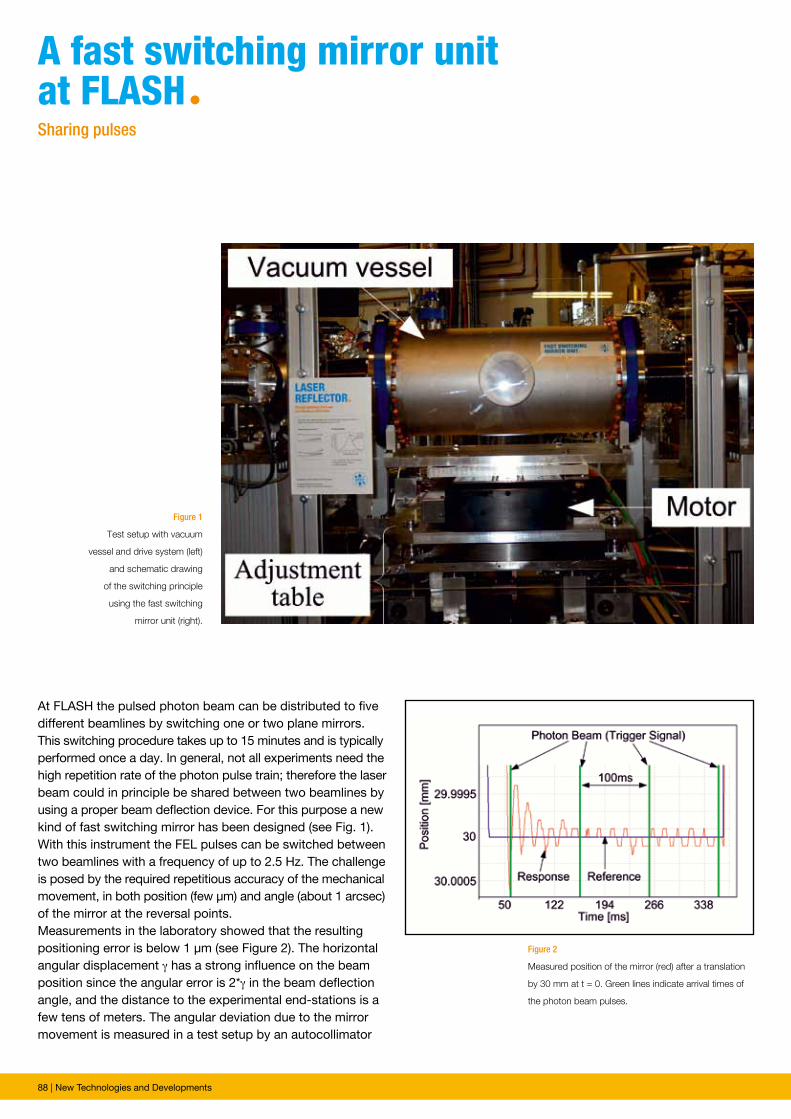
88 | New Technologies and Developments
Figure 1
Test setup with vacuum
vessel and drive system (left)
and schematic drawing
of the switching principle
using the fast switching
mirror unit (right).
Figure 2
Measured position of the mirror (red) after a translation
by 30 mm at t = 0. Green lines indicate arrival times of
the photon beam pulses.
At FLASH the pulsed photon beam can be distributed to five different beamlines by switching one or two plane mirrors. This switching procedure takes up to 15 minutes and is typically performed once a day. In general, not all experiments need the high repetition rate of the photon pulse train; therefore the laser beam could in principle be shared between two beamlines by using a proper beam deflection device. For this purpose a new kind of fast switching mirror has been designed (see Fig. 1). With this instrument the FEL pulses can be switched between two beamlines with a frequency of up to 2.5 Hz. The challenge is posed by the required repetitious accuracy of the mechanical movement, in both position (few μm) and angle (about 1 arcsec) of the mirror at the reversal points. Measurements in the laboratory showed that the resulting positioning error is below 1 μm (see Figure 2). The horizontal angular displacement γ has a strong influence on the beam position since the angular error is 2*γ in the beam deflection angle, and the distance to the experimental end-stations is a few tens of meters. The angular deviation due to the mirror movement is measured in a test setup by an autocollimator
A fast switching mirror unit at FLAshªSharing pulses
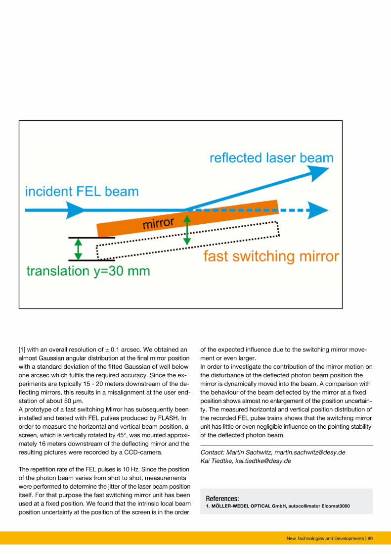
New Technologies and Developments | 89
Contact: Martin Sachwitz, [email protected] Tiedtke, [email protected]
References: 1. MÖLLER-WEDEL OPTICAL GmbH, autocollimator Elcomat3000
[1] with an overall resolution of ± 0.1 arcsec. We obtained an almost Gaussian angular distribution at the final mirror position with a standard deviation of the fitted Gaussian of well below one arcsec which fulfils the required accuracy. Since the ex-periments are typically 15 - 20 meters downstream of the de-flecting mirrors, this results in a misalignment at the user end-station of about 50 μm.A prototype of a fast switching Mirror has subsequently been installed and tested with FEL pulses produced by FLASH. In order to measure the horizontal and vertical beam position, a screen, which is vertically rotated by 45°, was mounted approxi-mately 16 meters downstream of the deflecting mirror and the resulting pictures were recorded by a CCD-camera.
The repetition rate of the FEL pulses is 10 Hz. Since the position of the photon beam varies from shot to shot, measurements were performed to determine the jitter of the laser beam position itself. For that purpose the fast switching mirror unit has been used at a fixed position. We found that the intrinsic local beam position uncertainty at the position of the screen is in the order
of the expected influence due to the switching mirror move-ment or even larger.In order to investigate the contribution of the mirror motion on the disturbance of the deflected photon beam position the mirror is dynamically moved into the beam. A comparison with the behaviour of the beam deflected by the mirror at a fixed position shows almost no enlargement of the position uncertain-ty. The measured horizontal and vertical position distribution of the recorded FEL pulse trains shows that the switching mirror unit has little or even negligible influence on the pointing stability of the deflected photon beam.
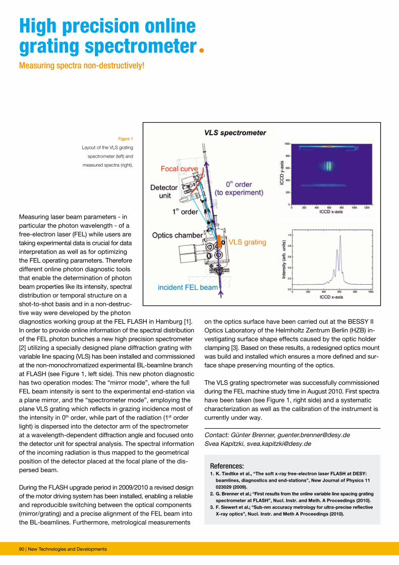
90 | New Technologies and Developments
Figure 1
Layout of the VLS grating
spectrometer (left) and
measured spectra (right).
Measuring laser beam parameters - in particular the photon wavelength - of a free-electron laser (FEL) while users are taking experimental data is crucial for data interpretation as well as for optimizing the FEL operating parameters. Therefore different online photon diagnostic tools that enable the determination of photon beam properties like its intensity, spectral distribution or temporal structure on a shot-to-shot basis and in a non-destruc-tive way were developed by the photon diagnostics working group at the FEL FLASH in Hamburg [1]. In order to provide online information of the spectral distribution of the FEL photon bunches a new high precision spectrometer [2] utilizing a specially designed plane diffraction grating with variable line spacing (VLS) has been installed and commissioned at the non-monochromatized experimental BL-beamline branch at FLASH (see Figure 1, left side). This new photon diagnostic has two operation modes: The “mirror mode”, where the full FEL beam intensity is sent to the experimental end-station via a plane mirror, and the “spectrometer mode”, employing the plane VLS grating which reflects in grazing incidence most of the intensity in 0th order, while part of the radiation (1st order light) is dispersed into the detector arm of the spectrometer at a wave length-dependent diffraction angle and focused onto the detector unit for spectral analysis. The spectral information of the incoming radiation is thus mapped to the geometrical position of the detector placed at the focal plane of the dis-persed beam.
During the FLASH upgrade period in 2009/2010 a revised design of the motor driving system has been installed, enabling a reliable and reproducible switching between the optical components (mirror/grating) and a precise alignment of the FEL beam into the BL-beamlines. Furthermore, metrological measurements
high precision online grating spectrometerªMeasuring spectra non-destructively!
Contact: Günter Brenner, [email protected] Kapitzki, [email protected]
References: 1. K. Tiedtke et al., “The soft x-ray free-electron laser FLASH at DESY: beamlines, diagnostics and end-stations”, New Journal of Physics 11 023029 (2009).2. G. Brenner et al.; “First results from the online variable line spacing grating spectrometer at FLASH”, Nucl. Instr. and Meth. A Proceedings (2010).3. F. Siewert et al.; “Sub-nm accuracy metrology for ultra-precise reflective X-ray optics”, Nucl. Instr. and Meth A Proceedings (2010).
on the optics surface have been carried out at the BESSY II Optics Laboratory of the Helmholtz Zentrum Berlin (HZB) in-vestigating surface shape effects caused by the optic holder clamping [3]. Based on these results, a redesigned optics mount was build and installed which ensures a more defined and sur-face shape preserving mounting of the optics.
The VLS grating spectrometer was successfully commissioned during the FEL machine study time in August 2010. First spectra have been taken (see Figure 1, right side) and a systematic characterization as well as the calibration of the instrument is currently under way.
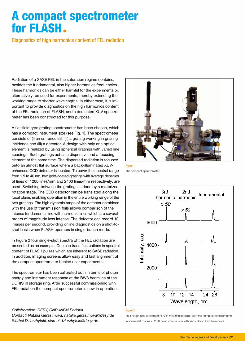
New Technologies and Developments | 91
Radiation of a SASE FEL in the saturation regime contains, besides the fundamental, also higher harmonics frequencies. These harmonics can be either harmful for the experiments or, alternatively, be used for experiments, thereby extending the working range to shorter wavelengths. In either case, it is im-portant to provide diagnostics on the high harmonics content of the FEL radiation of FLASH, and a dedicated XUV spectro-meter has been constructed for this purpose.
A flat-field type grating spectrometer has been chosen, which has a compact instrument size (see Fig. 1). The spectrometer consists of (i) an entrance slit, (ii) a grating working in grazing incidence and (iii) a detector. A design with only one optical element is realized by using spherical gratings with varied line spacings. Such gratings act as a dispersive and a focusing element at the same time. The dispersed radiation is focused onto an almost flat surface where a back-illuminated XUV- enhanced CCD detector is located. To cover the spectral range from 1.5 to 40 nm, two gold-coated gratings with average densities of lines of 1200 lines/mm and 2400 lines/mm respectively, are used. Switching between the gratings is done by a motorized rotation stage. The CCD detector can be translated along the focal plane, enabling operation in the entire working range of the two gratings. The high dynamic range of the detector combined with the use of transmission foils allows comparison of the intense fundamental line with harmonic lines which are several orders of magnitude less intense. The detector can record 10 images per second, providing online diagnostics on a shot-to-shot basis when FLASH operates in single-bunch mode.
In Figure 2 four single-shot spectra of the FEL radiation are presented as an example. One can trace fluctuations in spectral content of FLASH pulses which are inherent to SASE radiation. In addition, imaging screens allow easy and fast alignment of the compact spectrometer behind user experiments.
The spectrometer has been calibrated both in terms of photon energy and instrument response at the BW3 beamline of the DORIS III storage ring. After successful commissioning with FEL radiation the compact spectrometer is now in operation.
A compact spectrometer for FLAshªDiagnostics of high harmonics content of FEL radiation
Figure 1
The compact spectrometer.
Figure 2
Four single-shot spectra of FLASH radiation acquired with the compact spectrometer:
fundamental modes at 25.8 nm in comparison with second and third harmonics.
Collaboration: DESY, CNR-INFM PadovaContact: Natalia Gerasimova, [email protected] Dziarzhytski, [email protected]
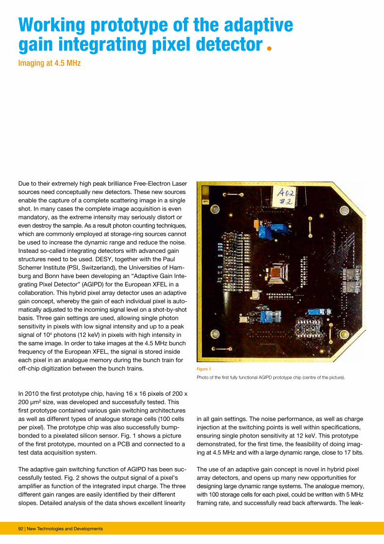
92 | New Technologies and Developments
Figure 1
Photo of the first fully functional AGIPD prototype chip (centre of the picture).
Due to their extremely high peak brilliance Free-Electron Laser sources need conceptually new detectors. These new sources enable the capture of a complete scattering image in a single shot. In many cases the complete image acquisition is even mandatory, as the extreme intensity may seriously distort or even destroy the sample. As a result photon counting techniques, which are commonly employed at storage-ring sources cannot be used to increase the dynamic range and reduce the noise. Instead so-called integrating detectors with advanced gain structures need to be used. DESY, together with the Paul Scherrer Institute (PSI, Switzerland), the Universities of Ham-burg and Bonn have been developing an “Adaptive Gain Inte-grating Pixel Detector” (AGIPD) for the European XFEL in a collaboration. This hybrid pixel array detector uses an adaptive gain concept, whereby the gain of each individual pixel is auto-matically adjusted to the incoming signal level on a shot-by-shot basis. Three gain settings are used, allowing single photon sensitivity in pixels with low signal intensity and up to a peak signal of 104 photons (12 keV) in pixels with high intensity in the same image. In order to take images at the 4.5 MHz bunch frequency of the European XFEL, the signal is stored inside each pixel in an analogue memory during the bunch train for off-chip digitization between the bunch trains.
In 2010 the first prototype chip, having 16 x 16 pixels of 200 x 200 µm² size, was developed and successfully tested. This first prototype contained various gain switching architectures as well as different types of analogue storage cells (100 cells per pixel). The prototype chip was also successfully bump-bonded to a pixelated silicon sensor. Fig. 1 shows a picture of the first prototype, mounted on a PCB and connected to a test data acquisition system.
The adaptive gain switching function of AGIPD has been suc-cessfully tested. Fig. 2 shows the output signal of a pixel’s amplifier as function of the integrated input charge. The three different gain ranges are easily identified by their different slopes. Detailed analysis of the data shows excellent linearity
Working prototype of the adaptive gain integrating pixel detector ªImaging at 4.5 MHz
in all gain settings. The noise performance, as well as charge injection at the switching points is well within specifications, ensuring single photon sensitivity at 12 keV. This prototype demonstrated, for the first time, the feasibility of doing imag-ing at 4.5 MHz and with a large dynamic range, close to 17 bits.
The use of an adaptive gain concept is novel in hybrid pixel array detectors, and opens up many new opportunities for designing large dynamic range systems. The analogue memory, with 100 storage cells for each pixel, could be written with 5 MHz framing rate, and successfully read back afterwards. The leak-
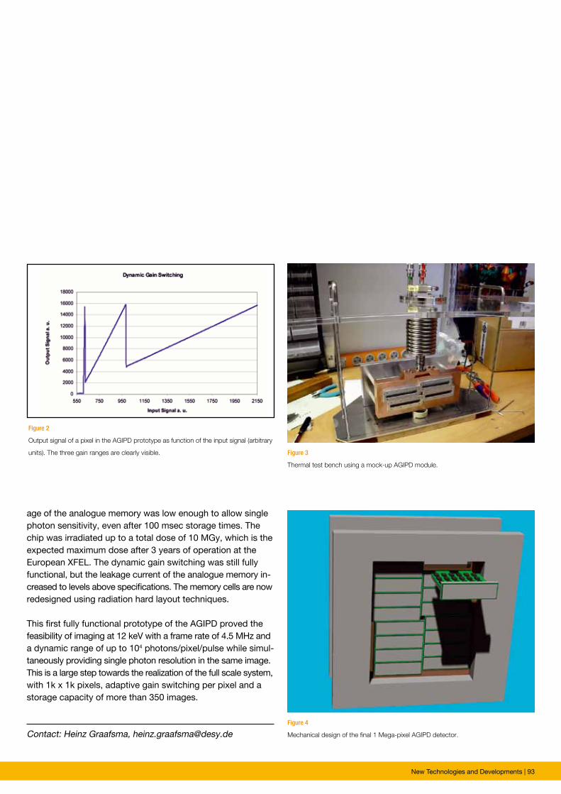
New Technologies and Developments | 93
Working prototype of the adaptive gain integrating pixel detector ª
Contact: Heinz Graafsma, [email protected]
Figure 2
Output signal of a pixel in the AGIPD prototype as function of the input signal (arbitrary
units). The three gain ranges are clearly visible.
Figure 4
Mechanical design of the final 1 Mega-pixel AGIPD detector.
Figure 3
Thermal test bench using a mock-up AGIPD module.
age of the analogue memory was low enough to allow single photon sensitivity, even after 100 msec storage times. The chip was irradiated up to a total dose of 10 MGy, which is the expected maximum dose after 3 years of operation at the European XFEL. The dynamic gain switching was still fully functional, but the leakage current of the analogue memory in-creased to levels above specifications. The memory cells are now redesigned using radiation hard layout techniques.
This first fully functional prototype of the AGIPD proved the feasibility of imaging at 12 keV with a frame rate of 4.5 MHz and a dynamic range of up to 104 photons/pixel/pulse while simul-taneously providing single photon resolution in the same image. This is a large step towards the realization of the full scale system, with 1k x 1k pixels, adaptive gain switching per pixel and a storage capacity of more than 350 images.
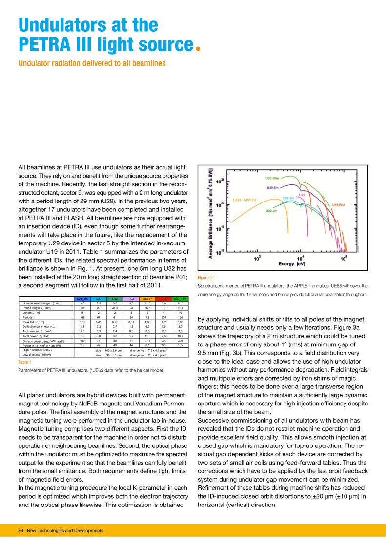
94 | New Technologies and Developments
Figure 1
Spectral performance of PETRA III undulators; the APPLE II undulator UE65 will cover the
entire energy range on the 1st harmonic and hence provide full circular polarization throughout.
Table 1
Parameters of PETRA III undulators. (*UE65 data refer to the helical mode)
All beamlines at PETRA III use undulators as their actual light source. They rely on and benefit from the unique source properties of the machine. Recently, the last straight section in the recon-structed octant, sector 9, was equipped with a 2 m long undulator with a period length of 29 mm (U29). In the previous two years, altogether 17 undulators have been completed and installed at PETRA III and FLASH. All beamlines are now equipped with an insertion device (ID), even though some further rearrange-ments will take place in the future, like the replacement of the temporary U29 device in sector 5 by the intended in-vacuum undulator U19 in 2011. Table 1 summarizes the parameters of the different IDs, the related spectral performance in terms of brilliance is shown in Fig. 1. At present, one 5m long U32 has been installed at the 20 m long straight section of beamline P01; a second segment will follow in the first half of 2011.
Undulators at the petRA iii light sourceªUndulator radiation delivered to all beamlines
All planar undulators are hybrid devices built with permanent magnet technology by NdFeB magnets and Vanadium Permen-dure poles. The final assembly of the magnet structures and the magnetic tuning were performed in the undulator lab in-house. Magnetic tuning comprises two different aspects. First the ID needs to be transparent for the machine in order not to disturb operation or neighbouring beamlines. Second, the optical phase within the undulator must be optimized to maximize the spectral output for the experiment so that the beamlines can fully benefit from the small emittance. Both requirements define tight limits of magnetic field errors. In the magnetic tuning procedure the local K-parameter in each period is optimized which improves both the electron trajectory and the optical phase likewise. This optimization is obtained
by applying individual shifts or tilts to all poles of the magnet structure and usually needs only a few iterations. Figure 3a shows the trajectory of a 2 m structure which could be tuned to a phase error of only about 1° (rms) at minimum gap of 9.5 mm (Fig. 3b). This corresponds to a field distribution very close to the ideal case and allows the use of high undulator harmonics without any performance degradation. Field integrals and multipole errors are corrected by iron shims or magic fingers; this needs to be done over a large transverse region of the magnet structure to maintain a sufficiently large dynamic aperture which is necessary for high injection efficiency despite the small size of the beam. Successive commissioning of all undulators with beam has revealed that the IDs do not restrict machine operation and provide excellent field quality. This allows smooth injection at closed gap which is mandatory for top-up operation. The re-sidual gap dependent kicks of each device are corrected by two sets of small air coils using feed-forward tables. Thus the corrections which have to be applied by the fast orbit feedback system during undulator gap movement can be minimized. Refinement of these tables during machine shifts has reduced the ID-induced closed orbit distortions to ±20 µm (±10 µm) in horizontal (vertical) direction.
U29_5m U29 U32 U23 UE65 * U19 U32_10m
Nominal minimum gap [mm] 9,5 9,5 9,5 9,5 11,0 7,0 12,5
Period length λU [mm] 29 29 31,4 23 65,6 19 31,4
Length L [m] 5 2 2 2 5 4 10
Periods 168 67 61 84 72 204 154
Peak field B0 [T] 0,81 0,81 0,91 0,61 1,03 0,7 0,68
Deflection parameter Kmax 2,2 2,2 2,7 1,3 6,3 1,24 2,0
1st Harmonic E1 [keV] 3,5 3,5 2,4 8,0 0,3 10,1 3,6
Total power Ptot [kW] 7,5 3,0 3,8 1,7 11,8 4,5 10,7
On-axis power dens. [kW/mrad2] 190 76 80 71 0,17 200 300
Power in 1x1mm2 at 40m [W] 119 47 49 44 0,1 122 185
High-β source (10keV)
Low-β source (10keV)
size : 140 x 5.6 µm2 divergence : 7.9 x 4.1 µrad2
size : 36 x 6.1 µm2 divergence : 28 x 4.0 µrad2
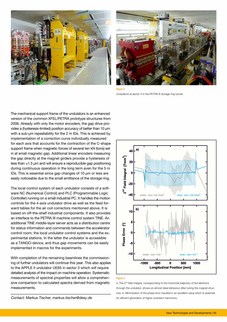
New Technologies and Developments | 95
Figure 3
a: The 2nd field integral, corresponding to the horizontal trajectory of the electrons
through the undulator, shows an almost ideal behaviour after tuning the magnet struc-
ture. b: Minimization of the phase error resulted in an excellent value which is essential
for efficient generation of higher undulator harmonics.
Figure 2
Undulators at sector 4 in the PETRA III storage ring tunnel.
Contact: Markus Tischer, [email protected]
The mechanical support frame of the undulators is an enhanced version of the common XFEL/PETRA prototype structures from 2006. Already with only the motor encoders, the gap drive pro-vides a (hysteresis-limited) position accuracy of better than 10 µm with a sub-µm repeatability for the 2 m IDs. This is achieved by implementation of a correction curve individually measured for each axis that accounts for the contraction of the C-shape support frame when magnetic forces of several ten kN (tons) set in at small magnetic gap. Additional linear encoders measuring the gap directly at the magnet girders provide a hysteresis of less than ±1.5 µm and will ensure a reproducible gap positioning during continuous operation in the long term even for the 5 m IDs. This is essential since gap changes of 10 µm or less are easily noticeable due to the small emittance of the storage ring.
The local control system of each undulator consists of a soft-ware NC (Numerical Control) and PLC (Programmable Logic Controller) running on a small industrial PC. It handles the motion controls for the 4-axis undulator drive as well as the feed for-ward tables for the air coil correctors mentioned above. It is based on off-the-shelf industrial components. It also provides an interface to the PETRA III machine control system TINE. An additional TINE middle-layer server acts as a distribution centre for status information and commands between the accelerator control room, the local undulator control systems and the ex-perimental stations. In the latter the undulator is accessible as a TANGO-device, and thus gap movements can be easily implemented in macros for the experiments.
With completion of the remaining beamlines the commission-ing of further undulators will continue this year. This also applies to the APPLE II undulator UE65 in sector 3 which will require detailed analysis of the impact on machine operation. Systematic measurements of spectral properties will allow a comprehen-sive comparison to calculated spectra derived from magnetic measurements.
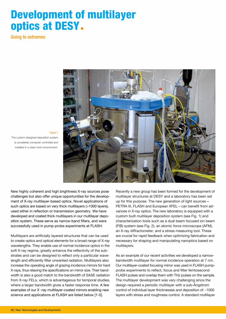
96 | New Technologies and Developments
Figure 1
The custom-designed deposition system
is completely computer controlled and
installed in a clean room environment.
New highly coherent and high brightness X-ray sources pose challenges but also offer unique opportunities for the develop-ment of X-ray multilayer-based optics. Novel applications of such optics are based on very thick multilayers (>1000 layers), used either in reflection or transmission geometry. We have developed and coated thick multilayers in our multilayer depo-sition system. These serve as narrow-band filters, and were successfully used in pump-probe experiments at FLASH. Multilayers are artificially layered structures that can be used to create optics and optical elements for a broad range of X-ray wavelengths. They enable use of normal incidence optics in the soft X-ray regime, greatly enhance the reflectivity of the sub-strates and can be designed to reflect only a particular wave-length and efficiently filter unwanted radiation. Multilayers also increase the operating angle of grazing incidence mirrors for hard X-rays, thus relaxing the specifications on mirror size. Their band-width is also a good match to the bandwidth of SASE radiation from X-ray FELs, which is advantageous for temporal studies, where a larger bandwidth gives a faster response time. A few examples of our X -ray multilayer-coated mirrors enabling new science and applications at FLASH are listed below [1-5].
Development of multilayeroptics at DesYªGoing to extremes
Recently a new group has been formed for the development of multilayer structures at DESY and a laboratory has been set up for this purpose. The new generation of light sources – PETRA III, FLASH and European XFEL – can benefit from ad-vances in X-ray optics. The new laboratory is equipped with a custom built multilayer deposition system (see Fig. 1) and characterization tools such as a dual beam focused ion beam (FIB) system (see Fig. 2), an atomic force microscope (AFM), an X-ray diffractometer, and a stress measuring tool. These are crucial for rapid feedback when optimizing fabrication and necessary for shaping and manipulating nanoptics based on multilayers.
As an example of our recent activities we developed a narrow-bandwidth multilayer for normal incidence operation at 7 nm. Our multilayer-coated focusing mirror was used in FLASH pump-probe experiments to reflect, focus and filter femtosecond FLASH pulses and overlap them with THz pulses on the sample. The multilayer development was very challenging since the design required a periodic multilayer with a sub-Ångstrom control of individual layer thicknesses and deposition of ~1000 layers with stress and roughness control. A standard multilayer
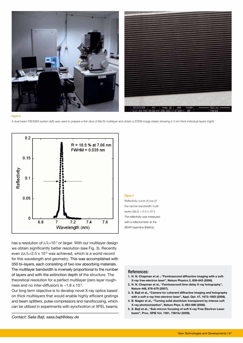
New Technologies and Developments | 97
Contact: Saša Bajt, [email protected]
References: 1. H. N. Chapman et al. ; “Femtosecond diffractive imaging with a soft- X-ray free-electron laser”, Nature Physics 2, 839–843 (2006).2. H. N. Chapman et al., “Femtosecond time-delay X-ray holography”, Nature 448, 676–679 (2007).3. S. Bajt et al., “Camera for coherent diffractive imaging and holography with a soft-x-ray free-electron laser”, Appl. Opt. 47, 1673–1683 (2008).4. B. Nagler et al., “Turning solid aluminium transparent by intense soft X-ray photoionization”, Nature Phys. 5, 693–696 (2009).5. S. Bajt et al., “Sub-micron focusing of soft X-ray Free Electron Laser beam”, Proc. SPIE Vol. 7361, 73610J (2009).
has a resolution of λ/λ=10-2 or larger. With our multilayer design we obtain significantly better resolution (see Fig. 3). Recently even ∆λ/λ=2.5 x 10-3 was achieved, which is a world record for this wavelength and geometry. This was accomplished with 350 bi–layers, each consisting of two low absorbing materials. The multilayer bandwidth is inversely proportional to the number of layers and with the extinction depth of the structure. The theoretical resolution for a perfect multilayer (zero layer rough-ness and no inter-diffusion) is ~1.8 x 10⁻³. Our long term objective is to develop novel X-ray optics based on thick multilayers that would enable highly efficient gratings and beam splitters, pulse compressors and nanofocusing, which can be utilized in experiments with synchrotron or XFEL beams.
Figure 2
A dual beam FIB/SEM system (left) was used to prepare a thin slice of Mo/Si multilayer and obtain a STEM image clearly showing 2-3 nm thick individual layers (right).
Figure 3
Reflectivity curve of one of
the narrow-bandwidth multi-
layers (∆λ/λ = 5.5 x 10⁻³).
The reflectivity was measured
with a reflectometer at the
BEAR beamline (Elettra).
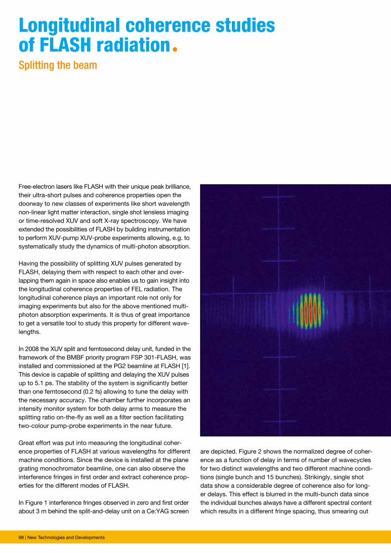
98 | New Technologies and Developments
Free-electron lasers like FLASH with their unique peak brilliance, their ultra-short pulses and coherence properties open the doorway to new classes of experiments like short wavelength non-linear light matter interaction, single shot lensless imaging or time-resolved XUV and soft X-ray spectroscopy. We have extended the possibilities of FLASH by building instrumentation to perform XUV-pump XUV-probe experiments allowing, e.g. to systematically study the dynamics of multi-photon absorption.
Having the possibility of splitting XUV pulses generated by FLASH, delaying them with respect to each other and over-lapping them again in space also enables us to gain insight into the longitudinal coherence properties of FEL radiation. The longitudinal coherence plays an important role not only for imaging experiments but also for the above mentioned multi-photon absorption experiments. It is thus of great importance to get a versatile tool to study this property for different wave-lengths.
In 2008 the XUV split and femtosecond delay unit, funded in the framework of the BMBF priority program FSP 301-FLASH, was installed and commissioned at the PG2 beamline at FLASH [1]. This device is capable of splitting and delaying the XUV pulses up to 5.1 ps. The stability of the system is significantly better than one femtosecond (0.2 fs) allowing to tune the delay with the necessary accuracy. The chamber further incorporates an intensity monitor system for both delay arms to measure the splitting ratio on-the-fly as well as a filter section facilitating two-colour pump-probe experiments in the near future.
Great effort was put into measuring the longitudinal coher-ence properties of FLASH at various wavelengths for different machine conditions. Since the device is installed at the plane grating monochromator beamline, one can also observe the interference fringes in first order and extract coherence prop-erties for the different modes of FLASH.
In Figure 1 interference fringes observed in zero and first order about 3 m behind the split-and-delay unit on a Ce:YAG screen
Longitudinal coherence studies of FLAsh radiationªSplitting the beam
are depicted. Figure 2 shows the normalized degree of coher-ence as a function of delay in terms of number of wavecycles for two distinct wavelengths and two different machine condi-tions (single bunch and 15 bunches). Strikingly, single shot data show a considerable degree of coherence also for long-er delays. This effect is blurred in the multi-bunch data since the individual bunches always have a different spectral content which results in a different fringe spacing, thus smearing out
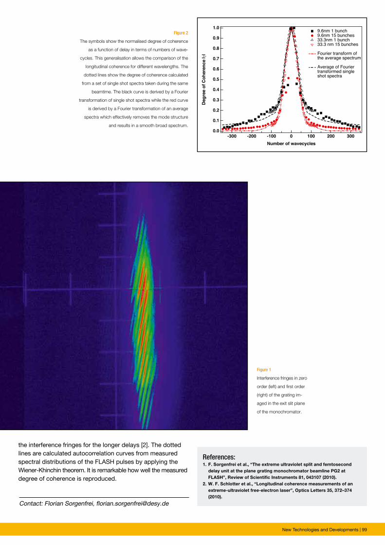
New Technologies and Developments | 99
Contact: Florian Sorgenfrei, [email protected]
References: 1. F. Sorgenfrei et al., “The extreme ultraviolet split and femtosecond delay unit at the plane grating monochromator beamline PG2 at FLASH”, Review of Scientific Instruments 81, 043107 (2010).2. W. F. Schlotter et al., “Longitudinal coherence measurements of an extreme-ultraviolet free-electron laser”, Optics Letters 35, 372–374 (2010).
the interference fringes for the longer delays [2]. The dotted lines are calculated autocorrelation curves from measured spectral distributions of the FLASH pulses by applying the Wiener-Khinchin theorem. It is remarkable how well the measured degree of coherence is reproduced.
Figure 1
Interference fringes in zero
order (left) and first order
(right) of the grating im-
aged in the exit slit plane
of the mono chromator.
Figure 2
The symbols show the normalised degree of coherence
as a function of delay in terms of numbers of wave-
cycles. This generalisation allows the comparison of the
longitudinal coherence for different wavelengths. The
dotted lines show the degree of coherence calculated
from a set of single shot spectra taken during the same
beamtime. The black curve is derived by a Fourier
transformation of single shot spectra while the red curve
is derived by a Fourier transformation of an average
spectra which effectively removes the mode structure
and results in a smooth broad spectrum.

100 | Facts and Numbers
Facts and numbersª
Facts and Numbers | 101
º Light source characteristics 102º Beamtime statistics 103º FLASH beamlines and parameters 104º PETRA III beamlines and parameters 107º DORIS III beamlines and parameters 110º Committees 2010 114
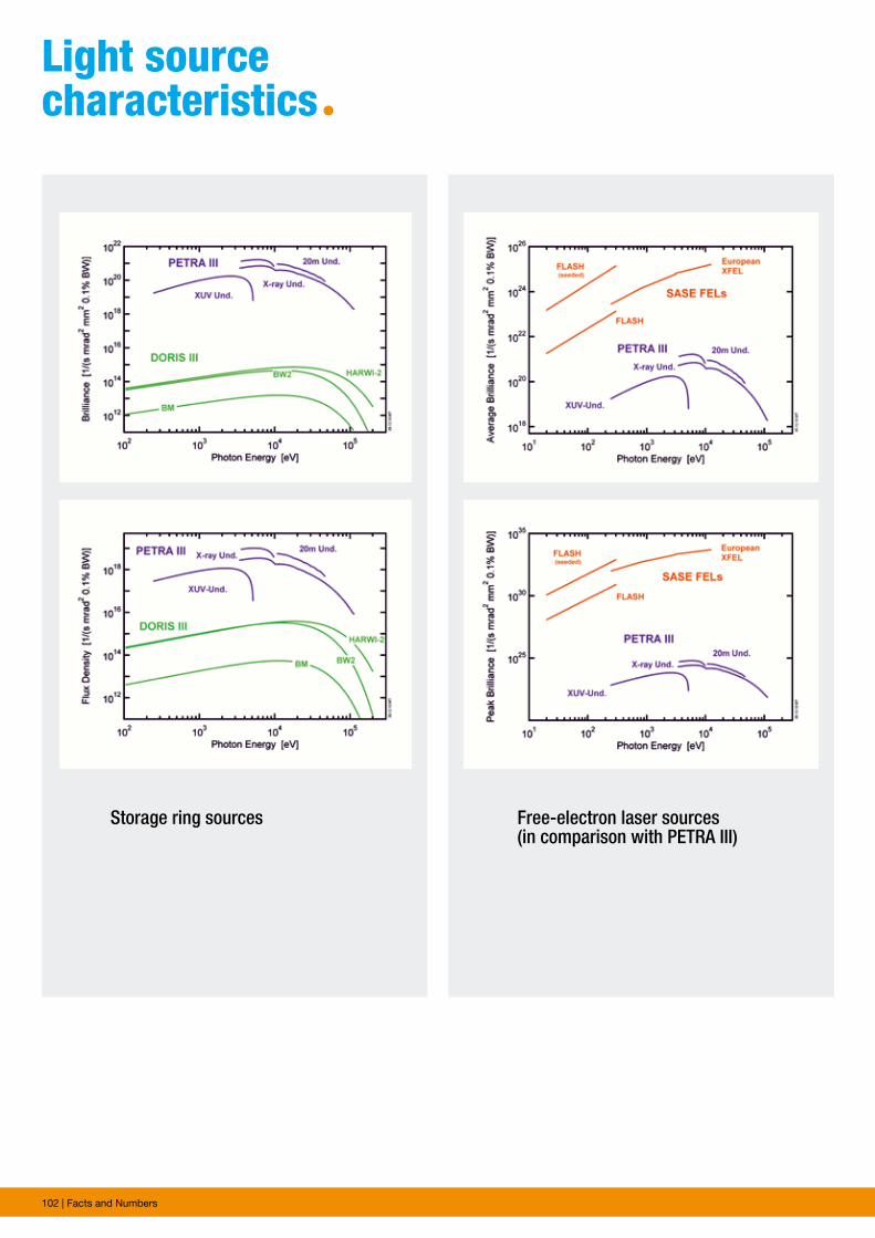
102 | Facts and Numbers
Light source characteristicsª
Storage ring sources Free-electron laser sources(in comparison with PETRA III)
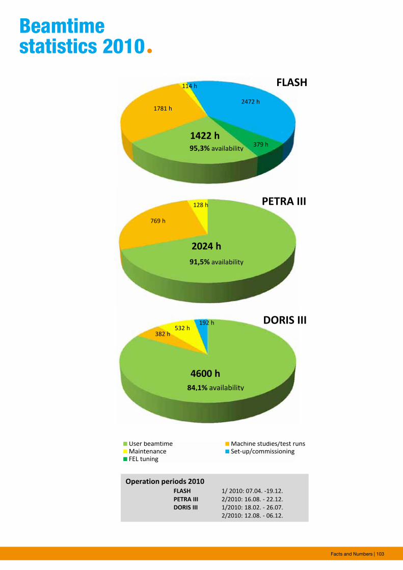
Facts and Numbers | 103
Beamtime statistics 2010ª
4600 h
382 h532 h
192 h
User beamtime Machine studies/test runsMaintenance Set‐up/commissioningFEL tuning
1422 h
1781 h
114 h
2472 h
379 h
FLASH
2024 h
769 h
128 h PETRA III
4600 h
382 h532 h
192 h DORIS III
95,3% availability
91,5% availability
84,1% availability
Operation periods 2010FLASH 1/ 2010: 07.04. ‐19.12.PETRA III 2/2010: 16.08. ‐ 22.12.DORIS III 1/2010: 18.02. ‐ 26.07.
2/2010: 12.08. ‐ 06.12.
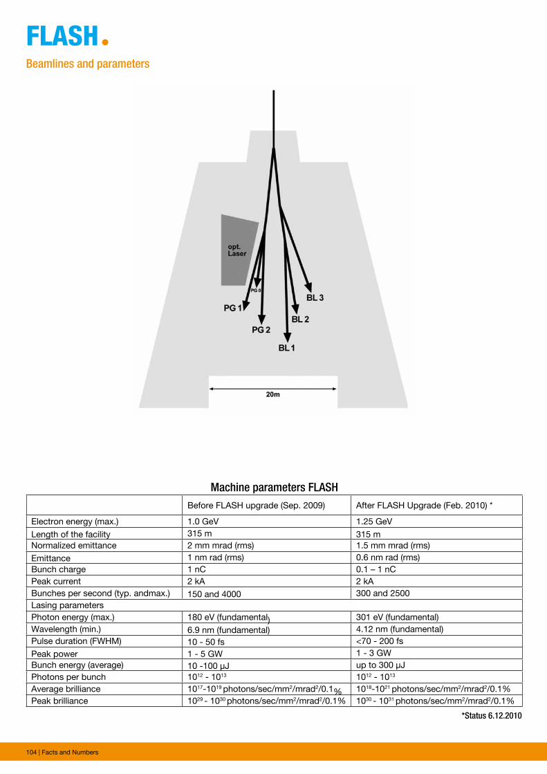
104 | Facts and Numbers
FLAshªBeamlines and parameters
Machine parameters FLASH Before FLASH upgrade (Sep. 2009) After FLASH Upgrade (Feb. 2010) *
Electron energy (max.) 1.0 GeV 1.25 GeVLength of the facility 315 m 315 m Normalized emittance 2 mm mrad (rms) 1.5 mm mrad (rms)Emittance 1 nm rad (rms) 0.6 nm rad (rms)Bunch charge 1 nC 0.1 – 1 nCPeak current 2 kA 2 kABunches per second (typ. andmax.) 150 and 4000 300 and 2500Lasing parametersPhoton energy (max.) 180 eV (fundamental) 301 eV (fundamental)Wavelength (min.) 6.9 nm (fundamental) 4.12 nm (fundamental)Pulse duration (FWHM) 10 - 50 fs <70 - 200 fsPeak power 1 - 5 GW 1 - 3 GWBunch energy (average) 10 -100 µJ up to 300 µJPhotons per bunch 1012 - 1013 1012 - 1013
Average brilliance 1017-1019 photons/sec/mm2/mrad2/0.1% 1018-1021 photons/sec/mm2/mrad2/0.1%Peak brilliance 1029
- 1030 photons/sec/mm2/mrad2/0.1% 1030 - 1031 photons/sec/mm2/mrad2/0.1%
*Status 6.12.2010
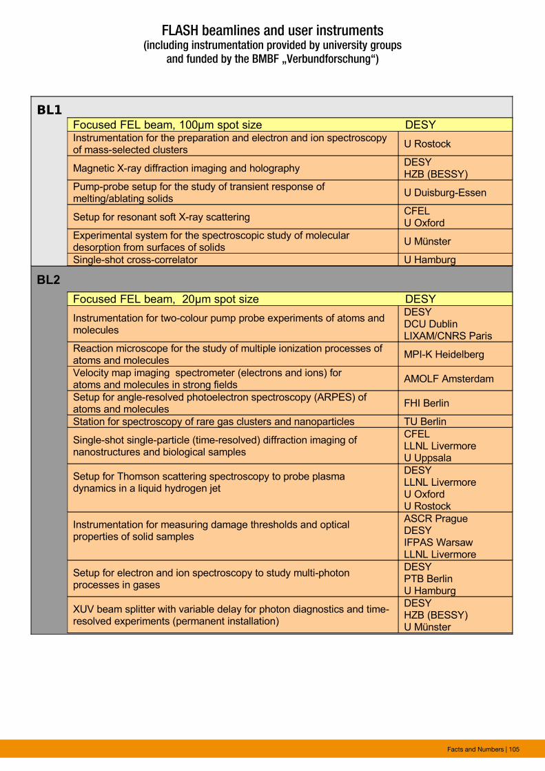
Facts and Numbers | 105
BL1
BL2
Focused FEL beam, 100μm spot size DESYInstrumentation for the preparation and electron and ion spectroscopy of mass-selected clusters
U Rostock
Magnetic X-ray diffraction imaging and holographyDESYHZB (BESSY)
Pump-probe setup for the study of transient response of melting/ablating solids
U Duisburg-Essen
Setup for resonant soft X-ray scatteringCFELU Oxford
Experimental system for the spectroscopic study of molecular desorption from surfaces of solids
U Münster
Single-shot cross-correlator U Hamburg
Focused FEL beam, 20μm spot size DESY
Instrumentation for two-colour pump probe experiments of atoms and molecules
DESYDCU DublinLIXAM/CNRS Paris
Reaction microscope for the study of multiple ionization processes of atoms and molecules
MPI-K Heidelberg
Velocity map imaging spectrometer (electrons and ions) for atoms and molecules in strong fields
AMOLF Amsterdam
Setup for angle-resolved photoelectron spectroscopy (ARPES) of atoms and molecules
FHI Berlin
Station for spectroscopy of rare gas clusters and nanoparticles TU Berlin
Single-shot single-particle (time-resolved) diffraction imaging of nanostructures and biological samples
CFELLLNL LivermoreU Uppsala
Setup for Thomson scattering spectroscopy to probe plasma dynamics in a liquid hydrogen jet
DESYLLNL LivermoreU OxfordU Rostock
Instrumentation for measuring damage thresholds and optical properties of solid samples
ASCR PragueDESYIFPAS WarsawLLNL Livermore
Setup for electron and ion spectroscopy to study multi-photon processes in gases
DESYPTB BerlinU Hamburg
XUV beam splitter with variable delay for photon diagnostics and time-resolved experiments (permanent installation)
DESYHZB (BESSY)U Münster
FLASH beamlines and user instruments(including instrumentation provided by university groups
and funded by the BMBF „Verbundforschung“)
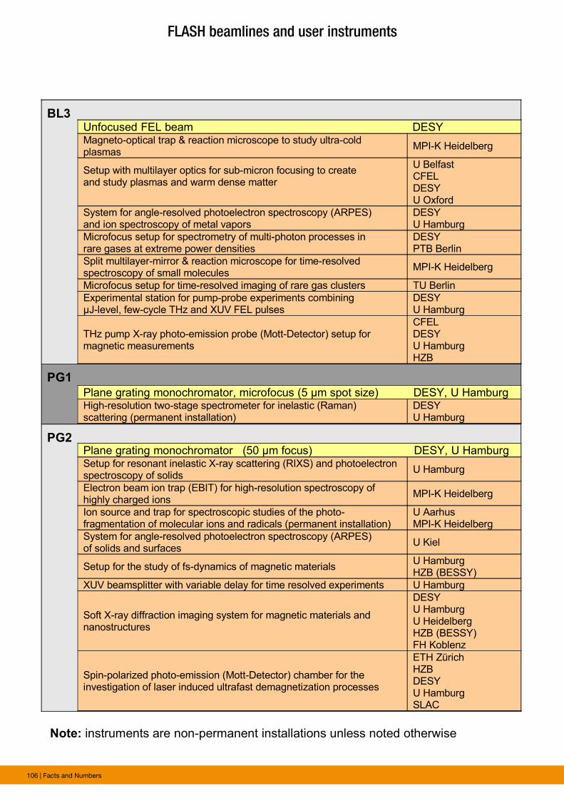
106 | Facts and Numbers
BL3
PG1
PG2
Note: instruments are non-permanent installations unless noted otherwise
Unfocused FEL beam DESYMagneto-optical trap & reaction microscope to study ultra-cold plasmas
MPI-K Heidelberg
Setup with multilayer optics for sub-micron focusing to create and study plasmas and warm dense matter
U BelfastCFELDESYU Oxford
System for angle-resolved photoelectron spectroscopy (ARPES) and ion spectroscopy of metal vapors
DESYU Hamburg
Microfocus setup for spectrometry of multi-photon processes in rare gases at extreme power densities
DESYPTB Berlin
Split multilayer-mirror & reaction microscope for time-resolved spectroscopy of small molecules
MPI-K Heidelberg
Microfocus setup for time-resolved imaging of rare gas clusters TU Berlin
Experimental station for pump-probe experiments combining µJ-level, few-cycle THz and XUV FEL pulses
DESYU Hamburg
THz pump X-ray photo-emission probe (Mott-Detector) setup for magnetic measurements
CFELDESYU HamburgHZB
Plane grating monochromator (50 μm focus) DESY, U HamburgSetup for resonant inelastic X-ray scattering (RIXS) and photoelectron spectroscopy of solids
U Hamburg
Electron beam ion trap (EBIT) for high-resolution spectroscopy of highly charged ions
MPI-K Heidelberg
Ion source and trap for spectroscopic studies of the photo-fragmentation of molecular ions and radicals (permanent installation)
U AarhusMPI-K Heidelberg
System for angle-resolved photoelectron spectroscopy (ARPES) of solids and surfaces
U Kiel
Setup for the study of fs-dynamics of magnetic materialsU HamburgHZB (BESSY)
XUV beamsplitter with variable delay for time resolved experiments U Hamburg
Soft X-ray diffraction imaging system for magnetic materials and nanostructures
DESYU HamburgU HeidelbergHZB (BESSY)FH Koblenz
Spin-polarized photo-emission (Mott-Detector) chamber for the investigation of laser induced ultrafast demagnetization processes
ETH ZürichHZBDESYU HamburgSLAC
Plane grating monochromator, microfocus (5 μm spot size) DESY, U HamburgHigh-resolution two-stage spectrometer for inelastic (Raman) scattering (permanent installation)
DESYU Hamburg
FLASH beamlines and user instruments
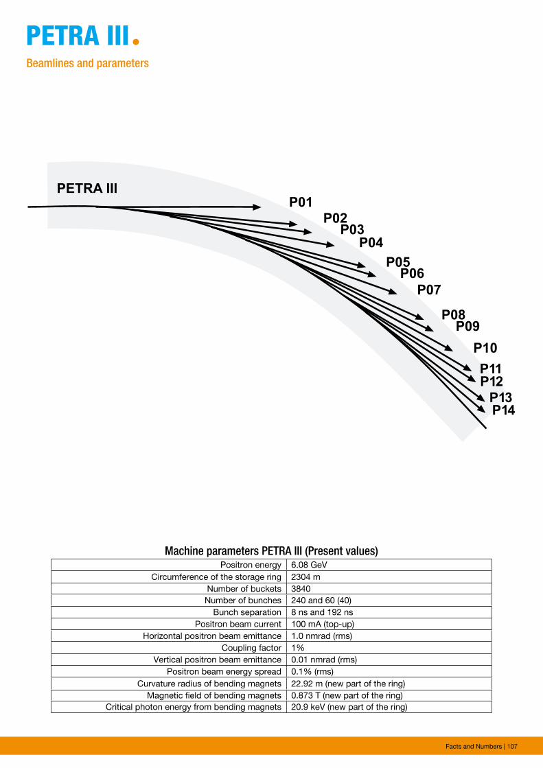
Facts and Numbers | 107
petRA iiiªBeamlines and parameters
������
������
���
���
���
���
���������
���
���
���
������
���
Machine parameters PETRA III (Present values)Positron energy 6.08 GeV
Circumference of the storage ring 2304 mNumber of buckets 3840
Number of bunches 240 and 60 (40)Bunch separation 8 ns and 192 ns
Positron beam current 100 mA (top-up)Horizontal positron beam emittance 1.0 nmrad (rms)
Coupling factor 1%Vertical positron beam emittance 0.01 nmrad (rms)
Positron beam energy spread 0.1% (rms)Curvature radius of bending magnets 22.92 m (new part of the ring)
Magnetic field of bending magnets 0.873 T (new part of the ring)Critical photon energy from bending magnets 20.9 keV (new part of the ring)
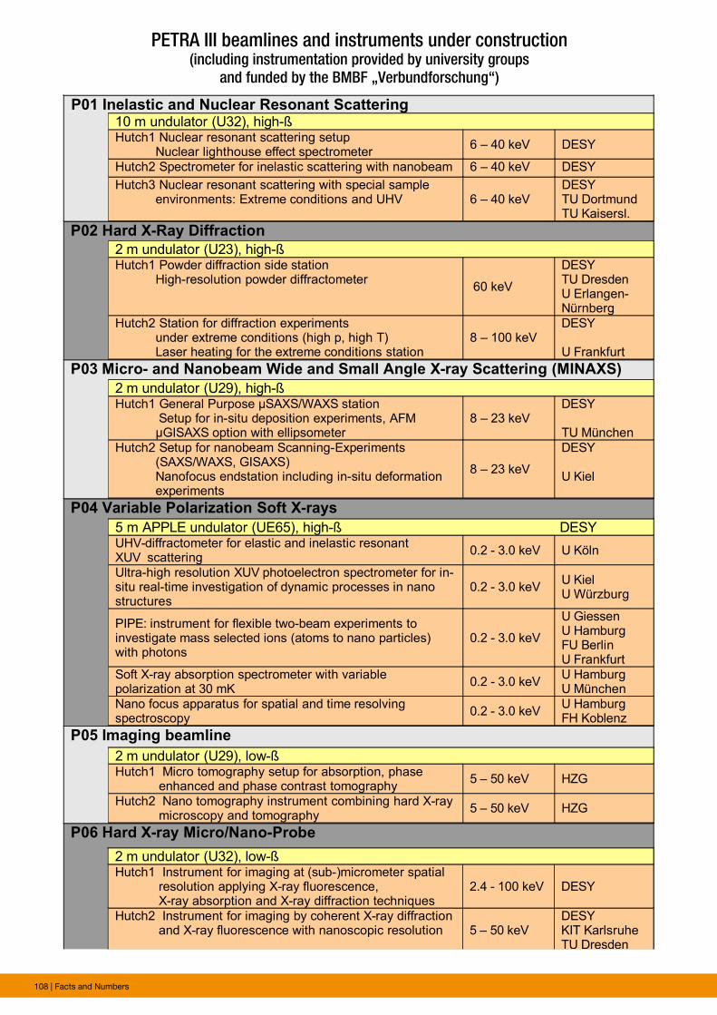
108 | Facts and Numbers
P01 Inelastic and Nuclear Resonant Scattering
P02 Hard X-Ray Diffraction
P03 Micro- and Nanobeam Wide and Small Angle X-ray Scattering (MINAXS)
P04 Variable Polarization Soft X-rays
P05 Imaging beamline
P06 Hard X-ray Micro/Nano-Probe
10 m undulator (U32), high-ßHutch1 Nuclear resonant scattering setup Nuclear lighthouse effect spectrometer
6 – 40 keV DESY
Hutch2 Spectrometer for inelastic scattering with nanobeam 6 – 40 keV DESY
Hutch3 Nuclear resonant scattering with special sample environments: Extreme conditions and UHV 6 – 40 keV
DESYTU DortmundTU Kaisersl.
2 m undulator (U23), high-ßHutch1 Powder diffraction side station High-resolution powder diffractometer
60 keV
DESYTU DresdenU Erlangen-Nürnberg
Hutch2 Station for diffraction experiments under extreme conditions (high p, high T) Laser heating for the extreme conditions station
8 – 100 keVDESY
U Frankfurt
2 m undulator (U29), high-ßHutch1 General Purpose µSAXS/WAXS station Setup for in-situ deposition experiments, AFM μGISAXS option with ellipsometer
8 – 23 keVDESY
TU München
Hutch2 Setup for nanobeam Scanning-Experiments (SAXS/WAXS, GISAXS) Nanofocus endstation including in-situ deformation experiments
8 – 23 keV
DESY
U Kiel
5 m APPLE undulator (UE65), high-ß DESYUHV-diffractometer for elastic and inelastic resonant XUV scattering
0.2 - 3.0 keV U Köln
Ultra-high resolution XUV photoelectron spectrometer for in-situ real-time investigation of dynamic processes in nano structures
0.2 - 3.0 keVU KielU Würzburg
PIPE: instrument for flexible two-beam experiments toinvestigate mass selected ions (atoms to nano particles) with photons
0.2 - 3.0 keV
U GiessenU HamburgFU BerlinU Frankfurt
Soft X-ray absorption spectrometer with variable polarization at 30 mK
0.2 - 3.0 keVU HamburgU München
Nano focus apparatus for spatial and time resolving spectroscopy
0.2 - 3.0 keVU HamburgFH Koblenz
2 m undulator (U29), low-ßHutch1 Micro tomography setup for absorption, phase enhanced and phase contrast tomography
5 – 50 keV HZG
Hutch2 Nano tomography instrument combining hard X-ray microscopy and tomography
5 – 50 keV HZG
2 m undulator (U32), low-ßHutch1 Instrument for imaging at (sub-)micrometer spatial resolution applying X-ray fluorescence, X-ray absorption and X-ray diffraction techniques
2.4 - 100 keV DESY
Hutch2 Instrument for imaging by coherent X-ray diffraction and X-ray fluorescence with nanoscopic resolution 5 – 50 keV
DESYKIT KarlsruheTU Dresden
PETRA III beamlines and instruments under construction(including instrumentation provided by university groups
and funded by the BMBF „Verbundforschung“)
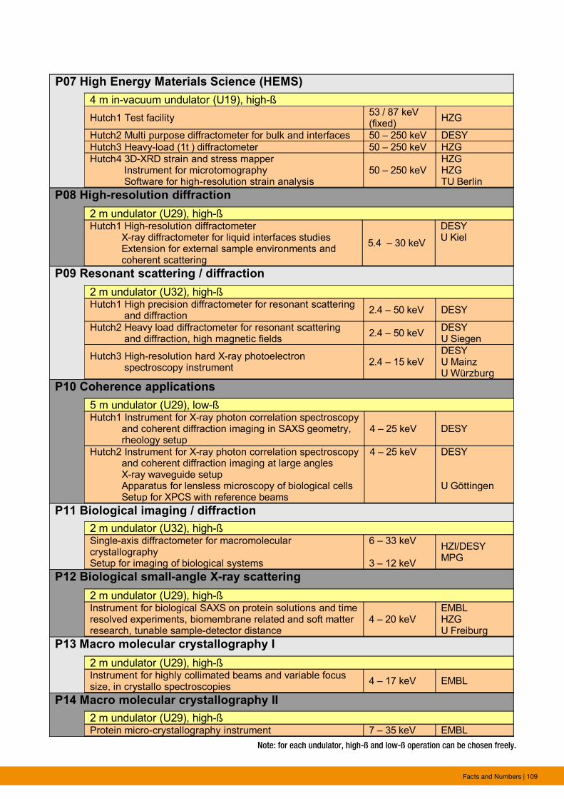
Facts and Numbers | 109
P07 High Energy Materials Science (HEMS)
P08 High-resolution diffraction
P09 Resonant scattering / diffraction
P10 Coherence applications
P11 Biological imaging / diffraction
P12 Biological small-angle X-ray scattering
P13 Macro molecular crystallography I
P14 Macro molecular crystallography II
Note: for each undulator, high-ß and low-ß operation can be chosen freely
4 m in-vacuum undulator (U19), high-ß
Hutch1 Test facility53 / 87 keV (fixed)
HZG
Hutch2 Multi purpose diffractometer for bulk and interfaces 50 – 250 keV DESY
Hutch3 Heavy-load (1t ) diffractometer 50 – 250 keV HZG
Hutch4 3D-XRD strain and stress mapper Instrument for microtomography Software for high-resolution strain analysis
50 – 250 keVHZGHZGTU Berlin
2 m undulator (U29), high-ßHutch1 High-resolution diffractometer X-ray diffractometer for liquid interfaces studies Extension for external sample environments and coherent scattering
5.4 – 30 keV
DESYU Kiel
5 m undulator (U29), low-ßHutch1 Instrument for X-ray photon correlation spectroscopy and coherent diffraction imaging in SAXS geometry, rheology setup
4 – 25 keV DESY
Hutch2 Instrument for X-ray photon correlation spectroscopy and coherent diffraction imaging at large angles X-ray waveguide setup Apparatus for lensless microscopy of biological cells Setup for XPCS with reference beams
4 – 25 keV DESY
U Göttingen
2 m undulator (U32), high-ßSingle-axis diffractometer for macromolecular crystallographySetup for imaging of biological systems
6 – 33 keV
3 – 12 keV
HZI/DESYMPG
2 m undulator (U29), high-ßInstrument for biological SAXS on protein solutions and timeresolved experiments, biomembrane related and soft matter research, tunable sample-detector distance
4 – 20 keVEMBLHZGU Freiburg
2 m undulator (U29), high-ßInstrument for highly collimated beams and variable focus size, in crystallo spectroscopies
4 – 17 keV EMBL
2 m undulator (U32), high-ßHutch1 High precision diffractometer for resonant scattering and diffraction
2.4 – 50 keV DESY
Hutch2 Heavy load diffractometer for resonant scattering and diffraction, high magnetic fields
2.4 – 50 keVDESYU Siegen
Hutch3 High-resolution hard X-ray photoelectron spectroscopy instrument
2.4 – 15 keVDESYU MainzU Würzburg
2 m undulator (U29), high-ßProtein micro-crystallography instrument 7 – 35 keV EMBL
Note: for each undulator, high-ß and low-ß operation can be chosen freely.
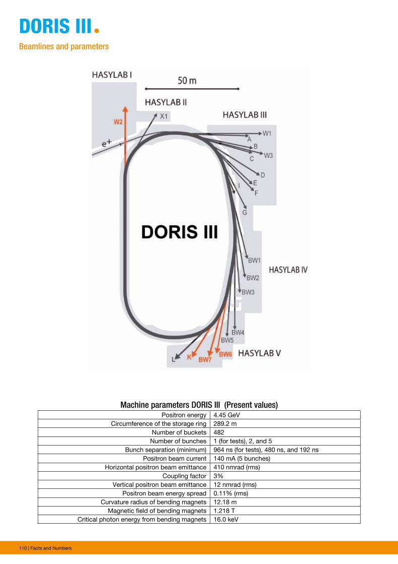
110 | Facts and Numbers
DoRis iiiªBeamlines and parameters
Machine parameters DORIS III (Present values) Positron energy 4.45 GeV
Circumference of the storage ring 289.2 mNumber of buckets 482
Number of bunches 1 (for tests), 2, and 5Bunch separation (minimum) 964 ns (for tests), 480 ns, and 192 ns
Positron beam current 140 mA (5 bunches)Horizontal positron beam emittance 410 nmrad (rms)
Coupling factor 3%Vertical positron beam emittance 12 nmrad (rms)
Positron beam energy spread 0.11% (rms)Curvature radius of bending magnets 12.18 m
Magnetic field of bending magnets 1.218 TCritical photon energy from bending magnets 16.0 keV
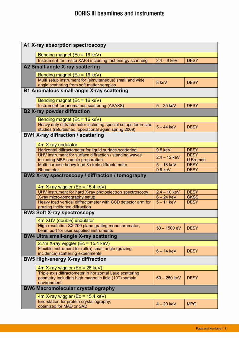
Facts and Numbers | 111
DORIS III beamlines and instruments
A1 X-ray absorption spectroscopy
A2 Small-angle X-ray scattering
B1 Anomalous small-angle X-ray scattering
B2 X-ray powder diffraction
BW1 X-ray diffraction / scattering
BW2 X-ray spectroscopy / diffraction / tomography
BW3 Soft X-ray spectroscopy
BW4 Ultra small-angle X-ray scattering
BW5 High-energy X-ray diffraction
BW6 Macromolecular crystallography
Bending magnet (Ec = 16 keV)
Instrument for in-situ XAFS including fast energy scanning 2.4 – 8 keV DESY
Bending magnet (Ec = 16 keV)Multi setup instrument for (simultaneous) small and wide angle scattering from soft matter samples
8 keV DESY
Bending magnet (Ec = 16 keV)Instrument for anomalous scattering (ASAXS) 5 – 35 keV DESY
Bending magnet (Ec = 16 keV)Heavy duty diffractometer including special setups for in-situ studies (refurbished, operational again spring 2009)
5 – 44 keV DESY
4m X-ray undulatorHorizontal diffractometer for liquid surface scattering 9.5 keV DESY
UHV instrument for surface diffraction / standing wavesincluding MBE sample preparation
2.4 – 12 keVDESY U Bremen
Multi purpose heavy load 8-circle diffractometer 5 – 18 keV DESY
Rheometer 9.9 keV DESY
4m X-ray wiggler (Ec = 15.4 keV)UHV instrument for hard X-ray photoelectron spectroscopy 2.4 – 10 keV DESY
X-ray micro-tomography setup 6 – 24 keV GKSS
Heavy load vertical diffractometer with CCD detector arm for grazing incidence diffraction
5 – 11 keV DESY
4m XUV (double) undulator High-resolution SX-700 plane grating monochromator,beam port for user supplied instruments
50 – 1500 eV DESY
2.7m X-ray wiggler (Ec = 15.4 keV)Flexible instrument for (ultra) small angle (grazing incidence) scattering experiments
6 – 14 keV DESY
4m X-ray wiggler (Ec = 26 keV)Triple axis diffractometer in horizontal Laue scattering geometry including high magnetic field (10T) sample environment
60 – 250 keV DESY
4m X-ray wiggler (Ec = 15.4 keV)End-station for protein crystallography, optimized for MAD or SAD
4 – 20 keV MPG
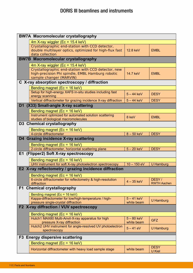
112 | Facts and Numbers
BW7A Macromolecular crystallography
BW7B Macromolecular crystallography
C X-ray absorption spectroscopy / diffraction
D1 (X33) Small-angle X-ray scattering
D3 Chemical crystallography
D4 Grazing incidence X-ray scattering
E1 (Flipper2) Soft X-ray spectroscopy
E2 X-ray reflectometry / grazing incidence diffraction
F1 Chemical crystallography
F2 X-ray diffraction / VUV spectroscopy
F3 Energy dispersive scattering
Bending magnet (Ec = 16 keV)Setup for high-energy XAFS in-situ studies including fast energy scanning
5 – 44 keV DESY
Vertical diffractometer for grazing incidence X-ray diffraction 5 – 44 keV DESY
Bending magnet (Ec = 16 keV)Instrument optimized for automated solution scattering studies of biological macromolecules
8 keV EMBL
Bending magnet (Ec = 16 keV)4-circle diffractometer 8 – 50 keV DESY
Bending magnet (Ec = 16 keV)2-circle diffractometer, horizontal scattering plane 5 – 20 keV DESY
Bending magnet (Ec = 16 keV)UHV instrument for soft X-ray photoelectron spectroscopy 10 – 150 eV U Hamburg
Bending magnet (Ec = 16 keV)6-circle diffractometer for reflectometry & high-resolution diffraction
4 – 35 keVDESY /RWTH Aachen
Bending magnet (Ec = 16 keV)
Kappa-diffractometer for low/high-temperature / high-pressure single-crystal diffraction
5 – 41 keVwhite beam
U Hamburg
Bending magnet (Ec = 16 keV)Hutch1 MAX80 Multi-Anvil-X-ray apparatus for high pressure X-ray diffraction
5 – 80 keVwhite beam
GFZ
Hutch2 UHV instrument for angle-resolved UV photoelectron spectroscopy
5 – 41 eV U Hamburg
Bending magnet (Ec = 16 keV)
Horizontal diffractometer with heavy load sample stage white beamDESYU Kiel
4m X-ray wiggler (Ec = 15.4 keV)Crystallographic end-station with CCD detector, double multilayer optics, optimized for high-flux fast data collection
12.8 keV EMBL
4m X-ray wiggler (Ec = 15.4 keV)Crystallographic end-station with CCD detector, new high-precision Phi spindle, EMBL Hamburg robotic sample changer (MARVIN)
14.7 keV EMBL
DORIS III beamlines and instruments
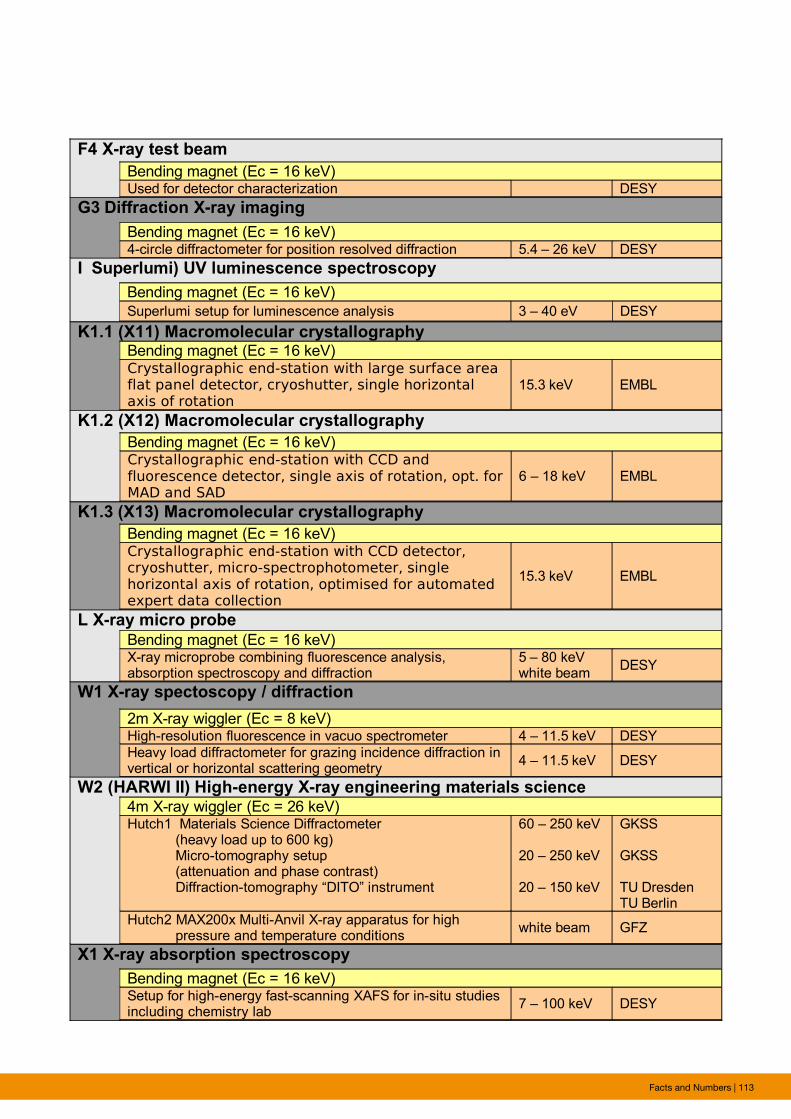
Facts and Numbers | 113
F4 X-ray test beam
G3 Diffraction X-ray imaging
I Superlumi) UV luminescence spectroscopy
K1.1 (X11) Macromolecular crystallography
K1.2 (X12) Macromolecular crystallography
K1.3 (X13) Macromolecular crystallography
L X-ray micro probe
W1 X-ray spectoscopy / diffraction
W2 (HARWI II) High-energy X-ray engineering materials science
X1 X-ray absorption spectroscopy
Bending magnet (Ec = 16 keV)Used for detector characterization DESY
Bending magnet (Ec = 16 keV)4-circle diffractometer for position resolved diffraction 5.4 – 26 keV DESY
Bending magnet (Ec = 16 keV)
Superlumi setup for luminescence analysis 3 – 40 eV DESY
Bending magnet (Ec = 16 keV)Crystallographic end-station with large surface area flat panel detector, cryoshutter, single horizontal axis of rotation
15.3 keV EMBL
Bending magnet (Ec = 16 keV)Crystallographic end-station with CCD and fluorescence detector, single axis of rotation, opt. for MAD and SAD
6 – 18 keV EMBL
Bending magnet (Ec = 16 keV)Crystallographic end-station with CCD detector, cryoshutter, micro-spectrophotometer, single horizontal axis of rotation, optimised for automated expert data collection
15.3 keV EMBL
Bending magnet (Ec = 16 keV)X-ray microprobe combining fluorescence analysis, absorption spectroscopy and diffraction
5 – 80 keVwhite beam
DESY
2m X-ray wiggler (Ec = 8 keV)High-resolution fluorescence in vacuo spectrometer 4 – 11.5 keV DESY
Heavy load diffractometer for grazing incidence diffraction in vertical or horizontal scattering geometry
4 – 11.5 keV DESY
4m X-ray wiggler (Ec = 26 keV)Hutch1 Materials Science Diffractometer (heavy load up to 600 kg) Micro-tomography setup (attenuation and phase contrast) Diffraction-tomography “DITO” instrument
60 – 250 keV 20 – 250 keV
20 – 150 keV
GKSS
GKSS
TU DresdenTU Berlin
Hutch2 MAX200x Multi-Anvil X-ray apparatus for high pressure and temperature conditions
white beam GFZ
Bending magnet (Ec = 16 keV)Setup for high-energy fast-scanning XAFS for in-situ studies including chemistry lab
7 – 100 keV DESY
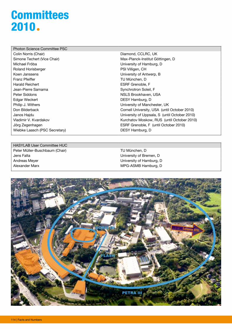
114 | Facts and Numbers
committees 2010ª
Photon Science Committee PSCColin Norris (Chair) Diamond, CCLRC, UKSimone Techert (Vice Chair) Max-Planck-Institut Göttingen, DMichael Fröba University of Hamburg, DRoland Horisberger PSI Villigen, CHKoen Janssens University of Antwerp, BFranz Pfeiffer TU München, DHarald Reichert ESRF Grenoble, FJean-Pierre Samama Synchrotron Soleil, FPeter Siddons NSLS Brookhaven, USAEdgar Weckert DESY Hamburg, DPhilip J. Withers University of Manchester, UKDon Bilderback Janos HajduVladimir V. KvardakovJörg ZegenhagenWiebke Laasch (PSC Secretary)
Cornell University, USA (until October 2010)University of Uppsala, S (until October 2010)Kurchatov Moskow, RUS (until October 2010)ESRF Grenoble, F (until October 2010)DESY Hamburg, D
HASYLAB User Committee HUCPeter Müller-Buschbaum (Chair) TU München, DJens Falta University of Bremen, DAndreas Meyer University of Hamburg, DAlexander Marx MPG-ASMB Hamburg, D

Facts and Numbers | 115
Project Review Panel PRP1: VUV- and Soft X-Ray - SpectroscopyWolfgang Drube (PRP Secretary) DESY Hamburg, DLutz Kipp University of Kiel, DMarco Kirm University of Tartu, EEAndries Meijerink Debye Institute, NLJoseph Woicik NIST, USA
Project Review Panel PRP2: X-Ray - Hard Condensed Matter - SpectroscopyWolfgang Drube (PRP Secretary) DESY Hamburg, DJohannes Hendrik Bitter Utrecht University, NLMelissa Denecke KIT Karlsruhe, DThorsten Ressler TU Berlin, DChristina Streli TU Wien, A
Project Review Panel PRP3: X-Ray - Hard Condensed Matter - Diffraction and ImagingHermann Franz (PRP Secretary) DESY Hamburg, DHans Boysen University of München, DRaphael Hermann FZ Jülich, DChristan Kumpf FZ Jülich, DBert Müller University Basel, CHMartin Müller HZG Geesthacht, D
Project Review Panel PRP4: Soft X-Ray - FEL Experiments (FLASH)Josef Feldhaus (PRP Secretary) DESY Hamburg, DMassimo Altarelli European XFEL Hamburg, DRobert Donovan University of Edinburgh, UKRoger W. Falcone Lawrence Berkeley Lab., USAMaya Kiskinova Sincrotrone Trieste, IJon Marangos Imperial College London, UKJan Michael Rost Max-Planck-Institut Dresden, DChristian Schroer TU Dresden, DBernd Sonntag University of Hamburg, DUrs Staub PSI Villigen, CHSvante Svensson Uppsala University, SEdgar Weckert DESY Hamburg, DGwyn P. Williams Jefferson Laboratory, USA
Project Review Panel PRP5: X-Ray - Soft Condensed Matter / ScatteringRainer Gehrke (PRP Secretary) DESY Hamburg, DTiberio Ezquerra CSIC Madrid, EJochen S. Gutmann University of Mainz, DBeate Klösgen University of Southern Denmark, DKOskar Paris Max-Planck-Institut Potsdam, D
Project Review Panel PRP6: Methods and InstrumentationHorst Schulte-Schrepping (PRP Secretary) DESY Hamburg, DKawal Sawhney Diamond Light Source, UKFrank Siewert HZB Berlin, D
AcknowledgementWe would like to thank all authors and everyone who helped in the creation of this annual report.ª
photographs and Graphics:CFELDESYEMBLEuropean XFELGFZJörg HarmsHZGMax-Planck Unit for Structural Molecular BiologyHeiner Mueller-Elsner/Agentur-Focus.de, HamburgRüdiger Nehmzow, DüsseldorfReimo Schaaf, HamburgUniversity of Hamburg
Figures of the Research Highlights were reproduced by permission from authors or journals.
Imprintpublishing and contact:Hamburger Synchrotronstrahlungslabor HASYLABat Deutsches Elektronen-Synchrotron DESYA Research Centre of the Helmholtz AssociationNotkestr. 85D-22607 HAMBURG, Germany
Phone: +49 40 8998-2304Fax: +49 40 8998-4475
E-mail: [email protected]. and hasylab.desy.de
ISBN 978-3-935702-50-8
online version:hasylab.desy.de/annual_report
Realisation:Wiebke Laasch, Ralf Röhlsberger
editing:Stefan Düsterer, Rainer Gehrke, Heinz Graafsma, Christian Gutt, Wiebke Laasch, Wolfgang Morgenroth, Ralf Röhlsberger, Ulla Vainio, Martin von Zimmermann
Layout: Britta Liebaug, Heike Becker
printing: Heigener Europrint GmbH, Hamburg
copy deadline: December 2010
Reproduction including extracts is permitted subject to crediting the source.

Deutsches Elektronen-Synchrotron A Research Centre of the Helmholtz Association
The Helmholtz Association contributes to solving
major challenges facing society, science and
industry with top scientific achievements in six
research areas: Energy, Earth and Environment,
Health, Key Technologies, Structure of Matter,
Transport and Space. With 30 000 employees
in 16 research centres and an annual budget
of approximately 3 billion euros, the Helmholtz
Association is Germany’s largest scientific
organisation. Its work follows in the tradition
of the great natural scientist Hermann von
Helmholtz (1821-1894).
www.helmholtz.de