Embed Size (px)
Citation preview

Version 3.0
PhotoGraVUser Guide
The Power Tool for Laser Engraving Photographs

PhotoGrav©
Version 3.0
User GuideRevision 3.0.1
i

Copyright Information
ii
PhotoGrav Version 3 .0 User Guide
© 2007 ImageLaz, LLC. All rights reserved.
This document is for information purposes only. ImageLaz, LLC makes no warranties, expressed or implied.
Other brand and product names are trademarks or registered trademarks of the respective holders. Microsoft is a registered trademark and Windows is a registered trademark of the Microsoft Corporation.
The characteristics of the laser engravers modeled by PhotoGrav were taken from published specifications and review articles. The use of these characteristics does not represent an endorsement of Photograv by the respective laser engraver manufacturers nor a commitment to the specifications on the part of the manufacturers.
Information in this document is subject to change without notice and does not represent a commitment on the part of ImageLaz, LLC. The software described in this document is furnished under a license agreement. It is against the law to copy the software on any medium except as specifically allowed in the license or nondisclosure agreement. No part of this manual may be reproduced or retransmitted in any form or by any means, electronically or mechanically, including photocopying, recording, or information recording and retrieval systems, for any purpose other than the purchaser’s personal use, without the express written permission of ImageLaz, LLC.

Table of Contents
Introduction
Chapter 1: Getting Started
1.0 Using this Document1.1 System Requirements1.2 Preliminaries1.3 Installation / Setup1.4 Activation System & Licensing1.5 Quick Start Scenarios1.6 Additional Tutorial Scenarios
Chapter 2: Operational Overview
2.0 Introduction2.1 Functional Flow of Events2.2 Basic PhotoGrav Concepts2.3 Important PhotoGrav Information
Chapter 3: PhotoGrav Application
3.0 Introduction3.1 PhotoGrav Sessions3.2 Primary Toolbar3.3 Viewing Panes and Panels3.4 Interactive Mode 3.5 Cloning—Comparison of Results3.6 Machine Properties3.7 Automatic Updates
Chapter 4: Troubleshooting
4.0 Introduction 4.1 Solutions to PhotoGrav Problems 4.2 Technical Support
v
1-1
1-11-11-21-31-31-51-7
2-1
2-12-12-32-4
3-1
3-13-13-33-73-8
3-153-163-17
4-1
4-14-14-3
iii

Appendices
Appendix 1: Engraving Tips Appendix 2: Calculational Procedure for “Turn Time” Appendix 3: PhotoGrav and Clip Art Appendix 4: PhotoGrav Concepts and Design Appendix 5: PhotoGrav License Agreement
A1-1
A2-1A3-1A4-1A5-1A6-1
iv

PhotoGrav has been designed specifically for Laser Engravers. The objective of the program is to efficiently process digitized photographs so they can be engraved on a variety of common engraving materials with a high degree of confidence that the engraved photographs will be acceptable products.
Traditionally, the engraving of photographs has been difficult and has been a hit or miss endeavor resulting in many discarded objects. The process has been so difficult and costly, in fact, that many Engraving shops simply do not offer engraved photographs as one of their standard products. PhotoGrav has been designed to address this problem and does so in three ways:
1. It provides a set of powerful tools that have been found effective in processing photos for engraving.2. It provides an automated application of these tools to the subject photo.3. It provides a simulation of the engraving process for many common materials so the “engraved product” can be inspected before it is actually engraved.
Currently, PhotoGrav simulates more than 25 engraving materials including: cherry and walnut wood; clear and black-painted acrylic; black laser brass and anodized aluminum; a variety of generic leather materials; and many plastics with either a white or black core and with a variety of caps including brushed gold and most solid colors. PhotoGrav’s processing functions have been tuned and optimized for each of these materials and the appropriate optimized parameters are automatically loaded whenever a new material is selected. Further, PhotoGrav automatically compensates for the engraving peculiarities of each material in the process of creating the “engraver-ready” processed image. For example, photos to be engraved on clear acrylic are automatically mirror-imaged and produced at a “negative” polarity. Of course, you can override these automatic features at any time to produce special effects if so desired.
The PhotoGrav process is very simple: (1) You select the digitized image that you want to engrave, (2) You select the engraving material, and (3) You choose the Final Processing option within PhotoGrav. The next thing you see on your computer monitor is a simulation of what the image will look like when it is actually engraved on the material you have chosen. You can then save the image on disk and use your favorite image processing program, e.g., CorelDraw, to send the image to the engraver.
Of course, the simulated engraving might not look quite like you wanted so instead of saving the image on disk you can reprocess the image by “tweaking” the parameters that PhotoGrav had
v

originally chosen for the image. Most of the time, however, the automated processing in PhotoGrav is so good that you won’t be able to improve on the automated rendition no matter how long you tweak.
Using an energy and lens model, PhotoGrav has been calibrated for many laser engravers from the major manufacturers. However, PhotoGrav goes one step further in that it provides the capability that allows you to customize and automate PhotoGrav’s processing for your particular machine and for the particular materials that you use.
As a final note, we would like to point out that PhotoGrav has NOT been designed in a vacuum by computer scientists who have merely a passing acquaintance with a laser engraver. Rather, it has been designed by a team of engravers, physicists, and computer scientists who have pooled their experience, knowledge, and talents to result in a truly unique and remarkable product for the laser engraving community. This team wishes you all possible success in using PhotoGrav and welcomes your comments for improvements to future PhotoGrav versions.
vi

1 - 1
1.0 Using this Document
This document has two objectives: (1) To acquaint you with PhotoGrav so you can be productively using the program as rapidly as possible and (2) To serve as a complete reference source for all of PhotoGrav's components and operational characteristics.
To satisfy the first objective, chapters 1 and 2 have been written to present essential information and concepts in as concise a manner as possible. Chapter 1 provides the information necessary to install PhotoGrav and to begin using it almost immediately. A series of logically-connected scenarios, with screen shots, provides immediate hands-on experience and should give you a good idea of PhotoGrav's basic operational characteristics. Chapter 2 presents an overview of the flow of events within PhotoGrav, discusses some basic PhotoGrav concepts and rationale, and presents a summary of important information that you should know about the program.
The remainder of the chapters, especially chapters 3 and 4, provides a detailed reference source for all of PhotoGrav's features. Chapters 3 and 4 present detailed descriptions of PhotoGrav's Primary and Support windows, respectively. Chapter 5 describes how to use the program's Help capability and Chapter 6 explains what to do if you have any difficulties in using PhotoGrav. The Appendices present supplemental information in specialized areas.
At a minimum, after installing the program, you should read Sec. 1.4 and step through the scenario presented in that section. You should also definitely read Sec. 2.3, Important PhotoGrav Information. Preferably, to really understand and fully use PhotoGrav's extensive capabilities, you should read Chapters 1 and 2 in their entirety.
1.1 System Requirements
To use PhotoGrav, you need the following hardware and software:
Getting Started

1 - 2
Notes on Hardware Requirements:
PhotoGrav itself requires less than 30 MB of hard disk space for program and data files. However, several temporary disk files are created during PhotoGrav execution on the disk where you installed PhotoGrav. These files are used as temporary storage for some of the images which are generated during execution. The sizes of these temporary files are proportional to the size of the digitized photo which is to be engraved and thus the required hard disk space is a “soft” number which depends on your operational scenario. All PhotoGrav temporary files are deleted when PhotoGrav terminates execution.
1.2 Preliminaries
PhotoGrav requires that your computer monitor be set up to display a pixel depth of at least 32 bits per pixel. It is also desirable that the display resolution (desktop area) be set to at least 1024 x 768, but it is recommended to be set at a larger size.
Hardware
Minimum Configuration
500 MHz Intel or AMD processor or better128 megabytes (MB) of RAMCD-ROM or DVD-ROM driveHard disk with at least 50 MB of free space (see Notes below)Keyboard & Mouse1024 x 768 SVGA Video Card
Recommended Configuration
2 GHz multicore or faster Intel or AMD processorAt least 1 to 2 GB of RAMCD-ROM/DVD-ROM driveHard disk with 100 MB of free space (see Notes below)Keyboard & MouseAt least 32 MB SVGA Video card
Software
Windows 2000, Windows XP, Windows Vista

1 - 3
1.3 Installation / Setup
The installation process will create an icon for PhotoGrav and place that on your desktop as a shortcut and will also create a new Program Group under “PhotoGrav”. In all cases, the installation process will also create an Uninstall icon that allows you to easily remove PhotoGrav from your system. You may also use the “Add/Remove Programs” capability in the Control Panel to uninstall the program.
1.4 PhotoGrav Activation System and Licensing
When PhotoGrav is launched it checks to see if the software has been activated and authenticated for full use. PhotoGrav will permit full usage with an activation reminder up to 15 days from initial installation in order to give adequate time for the user to activate the software. No registration is required to activate the software and no personal information is transmitted across the internet.
1. Log in to Windows if you have not already done so.
2. Insert the CD into your CD-ROM drive.
3. If Autorun is enabled on your system, installation will start automatically. Otherwise, click Start, then Run and enter X:\setup.exe where X is your CD-ROM drive.
4. Click OK.
5. Follow the instructions on the screen.
Note: During installation you will be asked to enter your PhotoGrav serial number. It is located on page i (first page) of this document, printed directly on the PhotoGrav CD, and in Help→About PhotoGrav… menu item.
6. After Installation and until PhotoGrav is activated a Product Activation Screenwill give the remaining days left to activate the PhotoGrav product. PhotoGravallows up to 15 days to activate the software. For further information refer to Sec 1.4 on Activation.
7. After Installation and on the first time PhotoGrav is launched a Select Machine Type window will appear. Select the appropriate laser machine type from the list of available laser machine manufacturers and model types. For further information refer to Sec 3.6 on Machine Properties.

1 - 4
PhotoGrav Licensing and Activation System permits activations on two separate computer machines and reactivation as many times as needed. This policy allows PhotoGrav to be installed on any combination of two computers such as office/laptop, home/office, machine/office, etc.
There are four different methods of activation provided to conveniently assist in activating the PhotoGrav software product. These four methods of activation are via the Web, Email, Postal Mail, and Phone (see Fig. 1.4.1). The quickest method to activate the PhotoGrav software, assuming efficient internet capabilities, is to use the online PhotoGrav Activation System (see Fig. 1.4.2).
To activate the software and display the activation screen in Fig 1.4.1, open PhotoGrav and click Help→Activate PhotoGrav on the main menu bar. If an active internet connection is available then it is suggested to click the Get Activation Key (Web)… button for the quickest way to activate the software. If you prefer to use email then simply click on the Get Activation Key (Email)… button and on most computers your default email client will pop up and be filled in with the appropriate information. If the computer system is configured in such a way that the relevant information is already filled in then just click the Send button to send an activation request email and allow 24 hours for the Activation Key to be emailed back to the sending email address. The third method is to call ImageLaz Sales Dept and we will be happy to provide an Activation Key. The fourth and most inefficient method of activation is to send an activation request via postal mail to ImageLaz with the appropriate information and wait for the Activation Key to be sent back.
Fig. 1.4.1
Fig. 1.4.2
1 - 5
1.5 Quick Start Scenarios
This section provides a “Quick Start” to using PhotoGrav by presenting a simple, but typical, engraving scenario. It introduces PhotoGrav’s major features and controls and how they are used within the context of an actual engraving scenario. To successfully use this section you should have a basic understanding of Windows features and techniques. If you’re anxious to try PhotoGrav and you don’t like to read, then this section is for you. However, even if you consider yourself a PhotoGravexpert after completing this section, it is highly recommended that you step through the additional scenarios in Section 1.6 and then read Chapter 2 for a more complete understanding of how PhotoGravworks.
There are several definitions that one should have firmly in mind before tackling the Quick Startscenario. These definitions are listed below:
Original Image The image, in jpg, tif, png or bmp format, that is the input image to (Gray or Color) PhotoGrav. This image is the digitized photograph (either in color or
grayscale) that you want to engrave.
Engraved Image This is the processed image that PhotoGrav produces that should be sent (Binary) to your laser engraver. This image is a binary image (black & white) and
can be saved in either tif, png, or bmp format.
Simulation Image This is a simulation, produced by PhotoGrav, of what the engraved image will look like when engraved on the selected engraving material. This image is a 24-bit, true color image and can be saved in either jpg, tif, png or bmp format. This image is useful for customer proofs and for reference BUT is NOT the image to be sent to the laser engraver.
Scenario 1: Engrave a man’s photograph on cherry wood.
It is assumed that the man’s photograph has been previously digitized and stored as either a color or grayshaded image (in one of the supported image formats) on disk. This scenario will use the image “Image250.bmp” which has been furnished with PhotoGrav. This image should reside in the directory C:\[PhotoGrav Installation Directory]\SAMPLES.
Note: The image “Image250.bmp” has a dpi of 250. In general, the ratio of engraver dpi to image dpi should be an integer factor. So if your engraver has dpi’s like 150, 300, 600, . . , then in the following scenario you should use the image “Image300.dpi” which has a dpi of 300.

1 - 6
1. Start PhotoGrav by double clicking its icon or by choosing it from the Start menu. The opening “Splash” screen appears.
2. Click anywhere at any time on the opening screen or press any key to continue with PhotoGrav execution which always begins with a blank Session Window.
3. However, the very first time you run PhotoGrav, a “Select Machine Type” Window is automatically displayed. In that window, select your engraver type by clicking one of the option buttons. If you cannot find your engraver in the list of machines just Select “User Defined→Custom” and type in the relevant information. Then click OK to close thewindow.
4. Click Open Image and use the standard Windows dialog box to choose the image “Image250.bmp” which resides in the \SAMPLES subdirectory of the directory in which you installed PhotoGrav. The image should be displayed.
5. Click Select Material. (A list of engraving materials appears).
6. Scroll down the list and select “Cherry with light vertical grain” and click OK. (“Cherry with light vertical grain” shows up in the status bar pane at the bottom of the PhotoGravapplication window).
7. Click Final Process. (A status message informs you of PhotoGrav’s progress permitting you to CANCEL the operation if needed at the first available point in the processing algorithm).
8. When processing is complete, a simulation of the engraving is displayed while permitting one to cycle through the various images by clicking on the appropriate buttons:
O = Original, G = Grayscale, E = Engraved, S = Simulated
9. Click on the Save Image button. At this point, if you wished to save the engraved image to disk in order to later send it to your engraver, you would select the “Engraved” option in the Export Image window that appears. A standard Windows dialog box would then appear in which you could specify the file name of the engraved (binary) image in the usual manner.
10. That’s all there is to it! You have created an image, the engraved image, which is ready to be sent to your laser engraver via your print software such as CorelDraw or your laser driver. You may now save the PhotoGrav Session if desired which will save the original image and all the appropriate material, machine, and session parameters in one PhotoGrav Session File (.pgs) .
At this point, either continue with scenario 2 (in Section 1.6) or click Exit to exit the PhotoGrav program.

1 - 7
1.6 Additional Tutorial Scenarios
This section presents five additional scenarios which further illustrate PhotoGrav’s features. Each scenario is a logical follow-on to Scenario 1 presented in the preceding section.
Scenario 2: Compare the original, grayscale, engraved, & simulated images.
This scenario will demonstrate how easy it is to evaluate the engraved (binary) image by comparing it and the simulated engraving to the original (input) or grayscale image. The scenario will also demonstrate some of PhotoGrav’s supporting features. PhotoGrav has a “Split Screen” feature which can be used to more efficiently compare the various images (i.e. grayscale vs. simulated).
1. If you are continuing here from Scenario 1, then go to the next step. Otherwise, repeat the first eight steps of Scenario 1.
2. Left click on the Split Window button. This will provide two separate viewing
windows to facilitate in the comparison of results.
3. Now click the Cycle Images button in either viewing pane to successively display the original, grayscale, engraved, and simulated images. Note that the four images have been enlarged by the same amount and are in synchronization to facilitate comparisons among the images.
4. Left click at a position between the man’s eyes on whichever image is displayed. The image will be magnified. Left click again at approximately the same point. The image will be enlarged more. (Note the scale factor in the lower right corner of the window).
5. Click with either mouse button anywhere on the gray area surrounding the displayed image. The display should now show the entire image. (The image can also be de-magnified in steps by clicking on the image with the right mouse button).
6. “Click and drag” on the image to define a rectangular area that you want magnified. After releasing the mouse button, the selected portion of the image will be magnified to fill the image area.
7. The simulation image and the ability to magnify and to cycle among the original, grayscale, engraved, and simulated images has been designed to help you decide whether or not the engraved image is a good representation of the original (input) or grayscale image on the engraving material you have chosen (cherry wood in this scenario).
At this point, either continue with scenario 3 or click Exit to exit the PhotoGrav program.

1 - 8
Scenario 3: Generating a PhotoGrav Session Information Report
This scenario will demonstrate how to generate a PhotoGrav Session Information Report that completely describes the current engraving session. The scenario will also demonstrate several other PhotoGrav features.
Notes:
1. If you are continuing here from Scenario 1 or Scenario 2, then go to the next step. Otherwise, repeat the first eight steps of Scenario 1.
2. Click the Display Info button located on the Primary Functions Toolbar.
The Session Info Report window should open and display all the relevant session
information including an estimate of engraving time.
3. Click on the lightest-gray box titled Engraver’s Comments.
Type in a comment such as: This session used the standard parameters for cherry wood.
4. Click the Print Report button near the bottom of the window. A standard Windows dialog box should appear allowing you to select a printer (if you have more than one) and to set the options for the selected printer. Your report should be printed after clicking OK in the standard dialog box.
5. Click the Close button next to the Engraver’s Comments button and the PhotoGrav Session Info Report window should disappear.
6. Refer to Figure 1.6.1 on the next page for the entire display of the PhotoGrav Session Info Report screen.
At this point, either continue with Scenario 4 or click Exit to exit the PhotoGrav program.

1 - 9
Fig. 1.6.1

1 - 10
Scenario 4: Adjusting Parameters in the “Interactive Mode” Panel.
This scenario will demonstrate how to adjust the parameters used in creating the engraved and simulation images. The Interactive Mode panel is extremely powerful, but also a little complicated so this scenario will just demonstrate some, not all, of the features available when Interactive Mode is selected. This scenario will also demonstrate how to export the Parameters.
1. If you are continuing here from Scenario 1, 2, or 3, then go to the next step. Otherwise, repeat the first eight steps of Scenario 1.
2. Click the Interactive Mode button located on the Primary Functions Toolbar. The Interactive Mode button should change to indicate that it is selected and the Parameter Adjustment view is displayed in the lower panel of the Session Window (see Fig. 1.6.2).
3. Components of the Interactive Mode panel:
If Split Window is selected (two viewing windows) and the input image is displayed in the left image pane and the output image (usually the simulated image) is displayed in the right image pane.
The seven green/red ON/OFF buttons represent the various processing functions that are applied to the input image. If a button is green, that function is “ON”. If the button is red, that function is “OFF”. There are also 8 sliders with corresponding text boxes for manual entry of the various parameters along with slider controls that adjust the histogram clipping region and the viewing range.
4. Within the “Simulate Engraving” panel, click the “Power” scroll bar (in the light gray area
under the scroll box) until its value is 20%. Now click the button (also on the
session toolbar see Fig 1.6.3) and note that the simulated image has gotten much lighter
reflecting the lower power setting for the engraving.
5. In a similar fashion, click the “Speed” scroll bar until its value is 30% followed by the
button. Again note that the simulation image is now about the same darkness
as was the case when Power was 70% and Speed was 100%.
6. Now, uncheck the check box and click the Reset button next to the
Power control then click the button. Note how much faster the simulated image
is displayed. If it is significantly faster then you may want to consider leaving this
unchecked unless you are working with a rather large image.

1 - 11
7. You may have noticed that every change you make requires you to click one of the Previewbuttons to view the changes. To see the changes in almost real time after every change ensure that the checkbox is checked and the checkbox is unchecked. Now change the Power back to 20% by either typing “20” into the textbox for the Powerparameter followed by pressing the [Enter] key or move the slider bar until the textbox reads 20% followed by releasing the mouse button. Note in either case how the simulated image is changed almost instantly. These options are included to provide some flexibility in previewing efficiency based on the speed of your computer and the size of the image.
8. Once you have adjusted the parameters to your satisfaction press the button to
hold the parameter changes and process the image in its entirety. The engraved/binary
image is now ready to be saved for engraving.
9. There are many other functions and features available when in Interactive Mode. See Section 3.2 of this PhotoGrav User Guide for a complete description of each of these functions.
At this point you can click Exit to exit the PhotoGrav program if you so choose.
Fig. 1.6.2
Fig. 1.6.3

1 - 12
Notes:

2-1
2.0 Introduction
The objective of this chapter is to present the essential information that you need to know in order to effectively use PhotoGrav. Section 2.1 briefly describes PhotoGrav's primary functions and flow of events that those functions support during a typical PhotoGrav session. Beginning with PhotoGravversion 3.0 multiple simultaneous PhotoGrav sessions can be opened, modified, and independently saved. Section 2.2 provides a concise, high-level description of the program's concepts and the rationale for those concepts. Finally, section 2.3 presents a list of items that summarize the important information about PhotoGrav.
2.1 Functional Flow of Events
PhotoGrav employs a small number of primary toolbar buttons to functionally organize the major steps involved in engraving a photograph. Each functional button has one or more major functions to accomplish and, upon completion of those functions, control passes back to the main session window. Figure 2.1.1 illustrates the normal flow of events in PhotoGrav processing.
The Open Image Button provides the capability to select the image that you want to engrave while the Select Material Button selects the engraving material that you want to use. PhotoGrav stores a set of processing parameters with each material that it models. These processing parameters are optimized for each particular material to ensure excellent engraving results without any user intervention. These optimized parameters make possible the “Final Process” path indicated in Fig 2.1-1.
Operational Overview
Fig. 2.1.1: PhotoGrav Functional Flow

2-2
The Resize Image Button provides the capability for you to resize/resample the input image without having to rely on another software application to perform this task. PhotoGrav will NOT resize or even modify the original image in any way because PhotoGrav makes a working copy of the original file. Also, on every resize/resample operation PhotoGrav uses the original image to perform the resize operation in order to maintain the highest degree of quality.
The Interactive Mode Button provides the capability to individually specify parameters for all of PhotoGrav’s processing functions and to view the result in near real time. Most importantly, one can view a simulation of what the engraving would actually look like on the material that you have selected. Although the Interactive Mode provides complete access to PhotoGrav’s functions that have been tuned specifically for Laser Engravers, you will probably find that you can seldom do better than PhotoGrav’s Automatic Final Processing option.
The Final Process Button (Auto Process in previous versions) allows the input image to be processed and finalized in the proper format for the laser engraver. To ensure that the image is processed and finalized with the latest modifications of the parameters this operation should ALWAYS be performed whether in Interactive Mode or otherwise prior to saving the image to disk.
The Viewing Panes (Figure 2.1.2), whether in split mode or otherwise, displays the Original(Input) image, the Grayscale image, the Engraved (Binary) image (the image that is to be used for engraving), and the Simulated image (what the engraving will look like on the selected material). The images appear on the screen one or two (if in split mode) at a time. One can, however, click a button to rapidly cycle through the various images for comparison purposes or view the images side by side when in split view mode. You can also magnify the images by clicking near the center of the area you want magnified or by defining a rectangular area to be enlarged to fill the screen. All three images are magnified by the same amount so comparisons are still easy to do even after magnification. Once the processed image is acceptable the various images can be save to disk for storing and to transfer to your engraver.
The Save Image Button allows the various images (Original, Grayscale, Engraved, Simulated) to be saved to disk (when appropriate) in the supported file formats i.e. jpg, tif, bmp, png. When saving the Engraved image the jpg file format is NOT permitted due to the fact that in most cases it would ruin the engraved image information which would not be suitable for engraving.
Fig. 2.1.2: Viewing Panes
Single Viewing Pane Split Viewing Pane

2-3
2.2 Basic PhotoGrav Concepts
The objective of the PhotoGrav program is to efficiently process digitized photographs so they can be engraved on a variety of common engraving materials with a high degree of confidence that the engraved photographs will be acceptable products. This objective is achieved via two basic PhotoGravconcepts:
1. Processing operations that are "tuned" for each engraving material, and2. A simulation of the engraved image
The intent of this section of the user guide is to provide a concise, high-level description of these two concepts and their underlying rationale. A more detailed description can be found in "Appendix 5: PhotoGrav Concepts and Design".
PhotoGrav's processing operations were designed and developed specifically to process images for laser engraving and were parameterized so that a wide range of effects could be achieved by adjustment of the parameters. Then the parameters were individually "tuned" for each of the engraving materials supported by the program. This "tuning" was accomplished experimentally, using several test images, by specifying several sets of parameters for each engraving material, actually engraving the images on the material, and evaluating the resulting engravings. This process was repeated until the resultant engravings appeared to be near optimal for the subject material. The parameters that produced the final, "near optimal' engraving were then recorded and a data set was created for the material. These data sets are stored as part of the description of each engraving material and are automatically retrieved whenever a material is selected as the current engraving material within PhotoGrav.
Although the tuning process described above results in "near optimal" parameter settings for each engraving material, engraving results are still often somewhat image dependent. In other words, the settings that produce an excellent engraving for one image on a specific material might result in an engraving that is less satisfactory for another image using the same engraving material. Further, it is very difficult to view the raw processed image on a computer monitor and to judge from that display whether or not the final engraving will be satisfactory. To overcome these difficulties, PhotoGravprovides, optionally, a simulation of what the processed image will look like once it is actually engraved on the selected material and the ability to modify the parameters as needed.
PhotoGrav's simulation capability is intended to provide a WYSIWYG (What You See Is What You Get) capability. In other words, the appearance of the simulated image on your computer monitor should be close to the appearance of the actual engraving produced from the processed image for most of the included materials. The simulated image is not merely an overlay of "dots" on top of a representation of the engraving material, but rather a convolution of the various parameters and images. In other words, it is a full-fledged simulation wherein a lens-power model, calibrated for each material, is used to calculate an effective laser spot size which is then "burned" into a representation of the engraving material. Further details about the simulation and model can be found in Appendix 5.
The Simulation Image produced by PhotoGrav should always be a representation of the final engraving. For example, for "Black Laser Brass", the Simulation Image should appear with proper polarity even though the processed image, if displayed in its "raw" form, would appear to have a "negative" polarity. There is one special case of this WYSIWYG capability that should be noted. For acrylics, which are normally engraved on the "back" of the material, the Simulation Image produced by

2-4
PhotoGrav is the view from the "front" of the material, i.e., the normal viewing perspective. So, even in this special case, the Simulation Image produced by PhotoGrav is a true WYSIWYG representation, i.e., the simulated engraving is presented as it would normally be viewed by your customers as a finished product. Although the primary utility of the Simulation Image is to help you make fine adjustments to create a more satisfactory engraving, it can also be printed and used for customer proofs or as supplements to file copies of your shop's projects. The prints are especially effective if you have a color printer attached to your computer.
Although the simulation model has been calibrated for a variety of laser engravers and for many common engraving materials, there are bound to be variables that at times cause noticeable differences between PhotoGrav's Simulation Image and the actual engraving. For example, black laser brass from different manufacturers, or even different "batches" from the same manufacturer, will sometimes engrave somewhat differently under identical engraver settings. Also, variables in the laser engraver itself, e.g., dirty lenses or mirrors, can cause variations in the engraving performance. You should try to control these variables to the degree possible and also realize that PhotoGrav, like any other tool, requires some practice and skill on your part to adapt its capabilities to your particular environment and requirements. It is also important to remember that, for engraved photographs, "beauty is in the eye of the beholder", i.e., the perceived goodness of an engraving is a very subjective measure. You might therefore find that PhotoGrav's processing parameters for a particular material do not result in engravings that match your tastes. If so, use PhotoGrav's interactive processing capabilities (see Sec. 3.4) and its Named Parameter Sets to define things the way you want them to be.
One other aspect of PhotoGrav's operational characteristics requires some discussion before concluding this section. In the Image Viewing Panes (see Fig. 2.1.2), PhotoGrav displays the Original Image, the Grayscale Image, the Engraved Image, and the Simulation Image for comparison purposes. The Grayscale Image is the input image and the Engraved Image is the processed binary image that is to be sent to the engraver. The Engraved Image is normally displayed in the same polarity and the same left-to-right orientation as the Grayscale Image even though those characteristics might be automatically changed by PhotoGrav when the image is saved on disk for transfer to your engraver. The reason for displaying the Engraved Image in this fashion is merely to facilitate the comparison to the input image. If this is a bit confusing, just remember that the Simulated Image always represents what will be engraved if you save the processed image (Engraved Image in PhotoGrav's terminology) to disk and transfer it to the engraver with no changes.
2.3 Important PhotoGrav Information
The following is a collection of important things that you should know about PhotoGrav. Some of the items have already been discussed in previous sections and some of them will be covered in later sections. However, since much of the information following Chapter 2 is very detailed and is intended as reference material, the essential elements of that information are summarized below so you can begin using PhotoGrav with confidence after reading this section. If an item is discussed elsewhere in this document, then a reference to the appropriate section is included below.

2-5
1. PhotoGrav has been designed for compatibility with a display screen color pixel depth of 32-bit and a resolution of 1024 x 768 or larger. (Reference: Sec. 3.3)
2. The input image ("Original/Grayscale Image") for PhotoGrav can be any image type in the following format: tif, bmp, jpg, png. (Reference: Sec. 3.2.2)
3. The input image to PhotoGrav should be scanned in some image processing program such as CorelDraw or Adobe PhotoShop, so that its size and resolution (dpi) are "correct". If the image is already in a digital format then PhotoGrav is able to resample the image to the desired size and resolution (dpi). Most images taken with a digital camera have an arbitrary resolution of either 72 or 96 dpi. In most engraving cases a dpi of 72 or 96 must be altered for best results.
The dpi (dots per inch) for the image should be the same, or an integer factor or divisor, of the dpi at which you intend to engrave the image. For example, if you intend to engrave at 250 or 500 dpi, then the image should be scanned at 250 dpi. If you intend to engrave at 300 or 600 dpi, then the image should be scanned at 300 dpi. Engraving results can often be very disappointing otherwise. The size of the image, at the scanned resolution (dpi), should be the desired size of the final engraved image.
4. Processed photographs (PhotoGrav's "Engraved Image") should be engraved using thehighest resolution lens (smallest spot size) that you have available. If you do not own your manufacturer's "high-resolution lens" and if you intend to engrave a lot of photographs, then you might consider obtaining such a lens.
5. Use PhotoGrav's “Machine Properties” or “Select Machine” dialog window to set the parameters and characteristics for your specific laser engraver. The “Machine Properties”window is accessible from the File→System Defaults→Select Machine menu item. The session “Machine Properties” can be modified by selecting Session→Select Machine from the menu bar. (Reference: Sec. 3.6)
Although you specified your Laser Engraver model and its maximum power on your very first PhotoGrav execution, there are other parameters that further define your specificmachine. In particular, within the “Machine Properties” window, you should add and/or delete lenses from the “Lenses” list to match your set of lenses. Similarly, the list of “dpi's” should be edited to reflect the dpi settings available on your machine. Also, if your laser engraver’s maximum wattage is not listed under “Watts” then add it to the list as well.
6. PhotoGrav is not designed to "Print" directly to laser engravers. To engrave a PhotoGravprocessed image (the "Engraved Image"), save the "Engraved Image" to disk and use your standard program, e.g., CorelDraw, to send the image to the engraver.
(Reference: Sec. 4.1.2.1)
7. DO NOT RESIZE NOR ROTATE the "Engraved Image" (the image to be sent to the engraver) in CorelDraw, or any other image processing program, before sending it to your engraver. The "Engraved Image" is a binary image, as it must be for laser engraving, and resizing and rotation operations in general do not work well for binary images.

2-6
8. PhotoGrav's “Sessions” provide a powerful mechanism whereby you can customize PhotoGrav's parameters to achieve the results you want and can be assured that those results are repeatable in the future. If PhotoGrav's default parameter settings do not provide a satisfactory result for a specific material after the “Final Process” button is pressed, then select the “Interactive Mode” button to create "Engraved Images" at several parameter settings that you suspect might be better. Save the various “Session’s” with different names and then actually engrave the images. Choose the engraving you prefer and then delete the “Session’s” that do not correspond to that “best” engraving. If satisfied with the “best” engraving, note which session was used and/or rename it so you can readily access it in the future for similar engraving projects. Otherwise, repeat the process until the results are satisfactory. You can now use this “Session” as a template to begin other similar “Session” types. (Reference: Sec. 3.1)
9. The engraving material to be modeled is selected via the “Material Properties” dialog window. The “Material Properties” dialog window can be accessed by selecting the File→System Defaults→Select Material menu item. The session “Material Properties” can be modified by selecting Session→Select Material from the menu bar.
(Reference: Sec. 3.2.3)
10. The leather materials included with PhotoGrav, unlike most of the other furnishedengraving materials, are not standardized materials. Further, the engraving behavior of leather depends very much on the tanning process, whether the leather is oiled or not, etc. therefore, PhotoGrav's Simulation Image for any specific leather material might not be agood representation relative to the specific leather material that you want to use. However, you can use the furnished material as a starting point for your own calibration process wherein you save your final, calibrated parameters as a PhotoGrav “Session File” Template.
11. The list of engraving materials includes two plastic materials that are “User-Defined Caps” with white or black cores. These materials can be used to model just about any plastic with a solid-color cap and with either a black or white core. Some calibration and parameter adjustment, as described in item 8 above, might be necessary for certain plastics and colors. (Reference: Sec. A1.1, Tip 5)
12. Two copies of PhotoGrav cannot be running at the same time. If PhotoGrav refuses tostart, there is probably another copy of PhotoGrav running in a minimized window.
13. PhotoGrav produces temporary image files during its execution that can become quitelarge if the input image is large. Try to maintain a reasonable quantity of free disk space on the hard disk where you installed PhotoGrav (200 MB should be more than adequate for most purposes).
14. PhotoGrav is a Windows 32-bit program which runs equally well under 2000, XP, and Vista. A 64-bit version is planned to be released and it is recommended that you call PhotoGrav or check online at www.photograv.com for the latest information.

3 - 1
3.0 Introduction
Chapter Two described PhotoGrav’s operational overview and how PhotoGrav uses these to provide a smooth flow of events within a PhotoGrav Session. This chapter, Chapter Three, provides a detailed description of each of those primary functional blocks as well as describing a PhotoGrav Session and the essentials of the PhotoGrav Application. The description with appropriate graphics include: (1) PhotoGrav Sessions, (2) The Primary Toolbar and its operations, (3) Viewing Panes and Panels, (4) Interactive Mode, (5) Cloning—Comparison of Results, (6) Machine Selection, and (7) Automatic Updates. It is especially recommended to become familiar with these primary functional blocks located on the Primary Toolbar and the respective operations since these are vital in producing a digital image for laser engraving.
3.1 PhotoGrav Sessions
One of PhotoGrav’s primary design concepts is the notion of a “PhotoGrav Session” and its respective “Session File” (*.pgs). A “Session File” is a file that is designed to save the current state of ones work including all parameter settings, user preferences, machine and material info, as well as the source image. By permitting the source image to be saved with the session alleviates the need to remember where the “original” image file is located. One can simply reopen the “Session File” and perform any necessary modifications and/or adjustments without having to relocate the original image. The machine information will be stored in the “Session File” which is helpful, for example, if PhotoGrav is used with multiple engravers. This permits one to save machine/material “templates” such that the user can just open up the session “template” pertaining to that particular machine/material and begin using PhotoGrav with the machine and material info already selected and defined.
Whenever an image is opened, PhotoGrav will automatically insert that image into either a newsession OR an existing active session. Either way there will always be only one image associated with a PhotoGrav Session.
Due to the “Session File” format, however, one must keep in mind that there are two modes of selecting a machine and/or material. These two modes are selecting the “Session” machine/material (Figure 3.1.1) and setting the “system” material/machine (Figure 3.1.2). The “Session” selection stays with that particular session and the “System Default” selection sets the default material/machine type
PhotoGrav Application

3- 2
so that any new session that is created will default to the machine/material type that is selected in the “System Default” settings.
Session files can be very useful when becoming proficient with PhotoGrav in the following ways; when working with a difficult image, if multiple engraving machines are used, when working with multiple concurrent jobs, and in many other cases as well. PhotoGrav allows multiple session files to be opened simultaneously and offers some functions specifically related to Session files such as Cloning (Figure 3.1.3). For further instruction on cloning refer to Section 3.5 on Cloning—Comparison of Results .
PhotoGrav has the capability to email Session files for easier review. For example PhotoGrav Session Files can be emailed to PhotoGrav Technical Support or to another office location for review simply by clicking on the Session→Email Session… menu item (Fig 3.1.4).
From this point forward the majority of this section is in the context of a “PhotoGrav Session” file (.pgs files).
Fig. 3.1.1: Session
Fig. 3.1.2: System Default
Fig. 3.1.3: Session Functions Fig. 3.1.4: Email Session

3 - 3
3.2 Primary Toolbar
3.2.1 Overview
PhotoGrav is designed for simplicity, therefore, all of the primary functions necessary to prepare an image for laser engraving are grouped together and displayed in the “Primary Toolbar” (Fig 3.2.1). The Primary Toolbar provides quick access to the most commonly used functions.
The Primary Toolbar has 5 basic functions that perform the minimum requirement operations to successfully laser engrave an image or photograph. As noted in Section 2.1 of this manual these 5 minimal steps are as follows:
1. Open an Image (Input Image).2. Select the engraving material.3. Resize the image to the desired size.4. Process the image.5. Save the image to disk.
3.2.2 Open Image
The Open Image button simply displays a dialog window that allows an image in any PhotoGravsupported file type (bmp, jpg, tif, png) to be opened and inserted into either a new or existing session window. While the open file dialog filters the listed items to only show PhotoGrav supported image types. If the “All files (*.*)” option is selected any PhotoGrav file type can be opened such as PhotoGrav Session Files (pgs), PhotoGrav Parameter Files (prm, pgp), or PhotoGrav Supported Image Files (bmp, jpg, tif, png).
The image that is initially opened is considered the “Original Image”. The image can be either color or grayscale. PhotoGrav then automatically converts the original image if necessary to a “Grayscale Image”. PhotoGrav considers the grayscale image because it is often much more reliable to compare the grayscale image (rather than the color image) to the engraved image.
1
Fig. 3.2.1: Primary Toolbar
54321
3- 4
3.2.3 Select Material
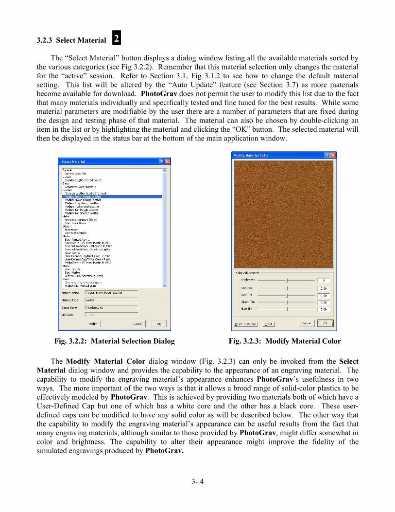
The “Select Material” button displays a dialog window listing all the available materials sorted by the various categories (see Fig 3.2.2). Remember that this material selection only changes the material for the “active” session. Refer to Section 3.1, Fig 3.1.2 to see how to change the default material setting. This list will be altered by the “Auto Update” feature (see Section 3.7) as more materials become available for download. PhotoGrav does not permit the user to modify this list due to the fact that many materials individually and specifically tested and fine tuned for the best results. While some material parameters are modifiable by the user there are a number of parameters that are fixed during the design and testing phase of that material. The material can also be chosen by double-clicking an item in the list or by highlighting the material and clicking the “OK” button. The selected material will then be displayed in the status bar at the bottom of the main application window.
The Modify Material Color dialog window (Fig. 3.2.3) can only be invoked from the Select Material dialog window and provides the capability to the appearance of an engraving material. The capability to modify the engraving material’s appearance enhances PhotoGrav’s usefulness in two ways. The more important of the two ways is that it allows a broad range of solid-color plastics to be effectively modeled by PhotoGrav. This is achieved by providing two materials both of which have a User-Defined Cap but one of which has a white core and the other has a black core. These user-defined caps can be modified to have any solid color as will be described below. The other way that the capability to modify the engraving material’s appearance can be useful results from the fact that many engraving materials, although similar to those provided by PhotoGrav, might differ somewhat in color and brightness. The capability to alter their appearance might improve the fidelity of the simulated engravings produced by PhotoGrav.
Fig. 3.2.2: Material Selection Dialog Fig. 3.2.3: Modify Material Color
2

3 - 5
The material to be modified can be chosen by clicking a material item in the list in Fig. 3.2.2 and then clicking the “Modify” button. Pressing the “Modify” button causes the Modify Material dialog window to appear.
The controls in the “Color Adjustments” frame are used to modify the appearance of the engraving material. The “Brightness” and “Contrast” controls affect the overall brightness and contrast of the material for all colors equally. The “Brightness” modification can range from -100 to +100 and the “Contrast” modification can range from -1.00 To + 1.00. The modification values can be changed only by clicking the scrollbars, not by direct numerical entries in the textboxes.
The “Red Tint”, “Green Tint”, and “Blue Tint” scrollbars change the contrast of the respective colors. The tint modifications can range from -1.00 to +1.00 and can be changed only by clicking the scrollbars, not by direct numerical entries in the text boxes.
Modifications caused by the adjustments are immediately visible in the material image view window. The “Reset” command button resets all of the scroll bars to the “no adjustment” state since the last time this material was modified. The “Reset to Default” button resets the adjustments to the default setting of the material, in other words to the settings of the material when originally shipped.
As an example try selecting the “User-Defined Cap/White Core” material type under plastics. And click “Modify”. Then adjust the “Green Tint” and “Blue Tint” slider bars so that both have a value of-1.00. Note that the effect of these values is that the material image view window turns from white to bright red. That red color could be further adjusted by changes in the “Brightness”, “Contrast”, and “Red Tint” scroll bars. The net result is that one can create almost any desired color for the cap of a solid-color plastic for which the core color can be either white (in the example) or black.
3.2.4 Resize/Resample Image
Resizing and/or Resampling the original input image (Fig 3.2.4) is almost always a requirement because one rarely receives the image in the actual size needed for engraving (this does vary some depending on the engravers policies). PhotoGrav offers the ability to resize/resample an image to the desired size without having to depend on other outside methods. PhotoGravwill raise a notification if it detects a discrepancy between the selected machine resolution (dpi) and the resolution (dpi) of the image. The image should be resampled to the same resolution (or an integer multiple of) as the desired engraving resolution (machine dpi setting). PhotoGravuses the machine settings extensively to prepare and simulate the image to give the user an idea, estimate, or relative difference of what to expect when the actual engraving is performed. Therefore, PhotoGrav does not adjust the “actual engraver” setting, which is usually modified through the software driver that comes with the engraver, but rather only adjusts the “machine setting” in PhotoGrav which is then used to prepare the image for engraving.
Fig. 3.2.4: Resize Image
3

3- 6
3.2.5 Final Process
The “Final Process” command button performs the actual processing necessary to produce an image ready for the laser engraver. This button should be pressed in every case prior to saving the image to disk. Once the “Final Process” button is clicked PhotoGrav will process the image using the current parameter settings. After the processing is complete PhotoGrav will switch the image viewing pane to either the “Engraved” image or the “Simulated” image determined by which image is selected in the viewing pane toolbar (see Section 3.3, Fig 3.3.2). There will now be a total of three or four images to use for comparison purposes in order to further fine tune the results if needed.
3.2.6 Save Image
Now that the material has been selected and the image has been opened, resized, and processed it is ready to be saved to disk for engraving (Fig 3.2.5). To do this simply select the “Save Images” button on the Primary Toolbar and save the appropriate images to disk in any of the PhotoGrav supported file formats. The only exception is the “Engraved” image which cannot be saved as a jpeg due to the fact this format usually uses a lossy compression type scheme which would create dire effects on the engraved image. One can elect to save the images while flipping either horizontally, vertically or both. One may find the “Flip Horizontal” check box to be turned on depending on the material type selected due to the fact that some material types such as acrylic engrave better on the back side, therefore requiring the image to be flipped or mirrored. This can be altered, however, by modifying the parameters when in Interactive Mode and then saving the session as a Template Session.
After the “Save Images” dialog is opened one must select the “Exit” button to close out of this dialog screen. The reason for this is that often it may be desirable to save more than just the “Engraved” image so this goes into a continuous loop until all images are saved as needed.
3.2.7 Display Info
The remaining buttons on the Primary Toolbar have to do with the way information is handled and viewed (see Fig 3.2.6). After pressing the “Display Info” button the “PhotoGrav Session Report” window will be displayed (Fig 1.6.1). This is a formatted report, that can be viewed or printed, of the parameter, machine, and image settings for a particular session. This report also includes thumbnail images of the original and simulated image types. This provides an opportunity to print and file every job performed while having quick access to all the data that was used for that job. One can also use it to quickly view all the relevant settings for a session in a neatly organized fashion. The PhotoGravSession Report is also where an estimate of the engraving time can be located and any comments that might be helpful relating to the active session.
4
5
Fig. 3.2.5: Save Image
6
3 - 7
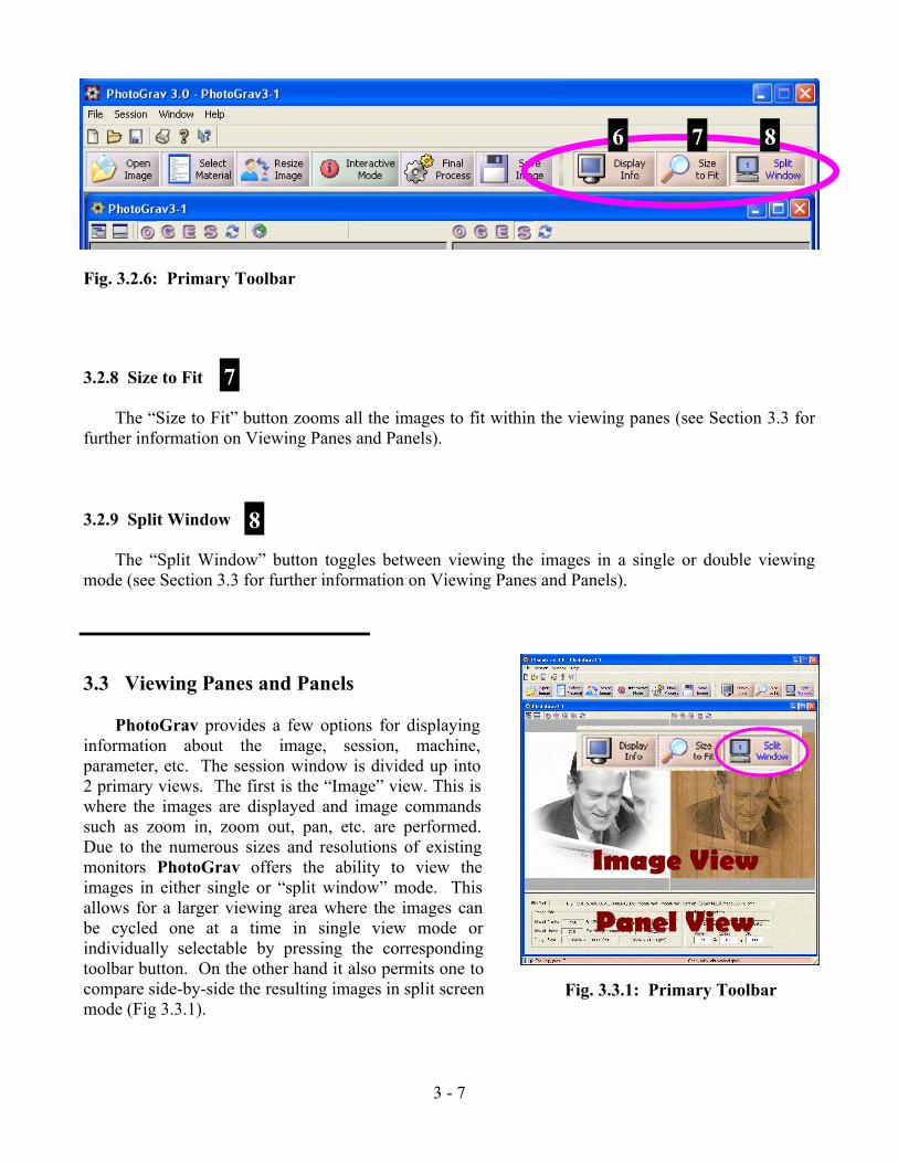
3.2.8 Size to Fit
The “Size to Fit” button zooms all the images to fit within the viewing panes (see Section 3.3 for further information on Viewing Panes and Panels).
3.2.9 Split Window
The “Split Window” button toggles between viewing the images in a single or double viewing mode (see Section 3.3 for further information on Viewing Panes and Panels).
3.3 Viewing Panes and Panels
PhotoGrav provides a few options for displaying information about the image, session, machine, parameter, etc. The session window is divided up into 2 primary views. The first is the “Image” view. This is where the images are displayed and image commands such as zoom in, zoom out, pan, etc. are performed. Due to the numerous sizes and resolutions of existing monitors PhotoGrav offers the ability to view the images in either single or “split window” mode. This allows for a larger viewing area where the images can be cycled one at a time in single view mode or individually selectable by pressing the corresponding toolbar button. On the other hand it also permits one to compare side-by-side the resulting images in split screen mode (Fig 3.3.1).
7
8
Fig. 3.2.6: Primary Toolbar
876
Fig. 3.3.1: Primary Toolbar
Panel View
Image View

3- 8
The second view that provides information is called the “Panel” view. The “Panel” view is further divided into two subsequent views named “Image Info” and “Parameter Info” (Fig 3.3.1). The “Image Info” panel (Fig 3.3.2) shows basic information about the image and the currently selected machine. The next sub panel is the “Parameter Info” panel (Fig 3.3.3) which displays a fixed summary of the current parameter settings. This “Parameter Info” view changes to permit adjustments and modifications to the parameters when in “Interactive Mode” which is discussed in Section 3.4.
These panel views can be hidden to again provide for larger viewing areas as needed by selecting the appropriate toolbar button from the PhotoGrav Session Toolbar (Fig 3.3.4).
There are four images that one can select for viewing namely Original input, Grayscale, Engraved/binary, and the Simulated images (Fig 3.3.5). If one has “Split Screen” selected then these images can be selected independently per image view. To open an image one can select the “Open Image” button on the primary command bar. This button can be selected even if there is no session window open in which case a new session window will be created and the respective image inserted into that session. If, on the other hand, an existing session is open then the selected image will be inserted over the existing image if an image exists. In other words, if the user already has a session open then he or she should create a “New” session prior to opening the image to prevent the replacement of the existing session’s image.
By left or right clicking of the mouse button in either one of the two Image View Windows one can incrementally zoom in or out respectively. It is also possible to drag a zoom “box” or rectangle around the desired area for closer inspection of the images. Another image command is the “pan” command. This command centers the image at the point where the mouse button was clicked. Holding down the [Space Bar] will activate this command (Fig 3.3.6).
Fig. 3.3.2: Image Info Fig. 3.3.3: Parameter Info
Fig. 3.3.6: Image Selection
Fig. 3.3.4: Hide/Show
Fig. 3.3.5: Image Selection

3 - 9
3.4 Interactive Mode
The Interactive ModeButton toggles between two modes of operation. When in “Interactive Mode” the Interactive Mode Button will show a green “i” icon indicating that PhotoGrav is in “Interactive Mode”. Similarly when PhotoGrav is NOT in “Interactive Mode” the button will display a red “i”.
The “Interactive Mode” is designed for the primary purpose of providing a quick and efficient preview of the final image, since with average size images it would simply take too long to run through the entire PhotoGrav processing pipeline every time a small change is made to a parameter. With this in mind PhotoGrav distinguishes between “Preview” and “Final Process”. The “Final Process” button (formerly called “Auto Process” in previous versions) takes the raw image data along with the current material, parameter, and machine settings and completely processes the image producing the binary or engraved image ready to be saved and engraved. On the other hand the “Preview” buttons (only available in “Interactive Mode” - Fig 3.4.2) process a scaled version of the image (NOT THE ORIGINAL IMAGE) suitable for rapid viewing as one adjusts and modifies the parameters in almost if not real time.
PhotoGrav does not restrict the image view display size therefore providing a larger viewing area for a more accurate representation of the resulting image. A larger viewing area does require more processing speed in order to maintain real time performance. The real time performance of interactively adjusting the parameter settings is a direct correlation to the size of the image and the size of the display screens viewing area. Since PhotoGrav permits arbitrary screen sizes it is better prepared to adapt to the increasing speeds of modern computers. Assuming 17” to 24” computer monitors and current average to high end computers one can expect almost real time performance when interacting with the parameters while in “Interactive Mode”.
Due to the plethora of monitor and display types, resolutions, and sizes that exist in the market place today PhotoGrav offers a couple of options to facilitate the advanced user who relies on the “Interactive Mode” in their production cycle. The first option is the “Auto Preview” checkbox (Fig 3.4.2). This is provided to give the user the ability to regenerate the preview image automatically after each parameter adjustment without the user having to manually click on the “Preview” buttons. The user may select to turn this on or off depending on the image size and/or display screen size to increase performance.
Fig. 3.4.2: Preview Buttons
Fig. 3.4.1: Primary Toolbar

3- 10
The second option is the “Progress Bar On” checkbox (Fig 3.4.2). This checkbox offers the user the option of increasing performance by turning this off. When the progress bar is turned off PhotoGravwill process the “Preview” image slightly faster, however, with larger images and depending on the speed of the users’ computer one may want to turn this on. By turning this on it gives a “heads up” as to what PhotoGrav is doing followed by an indication when the “Preview” image is ready for display.
Once the image and parameters are determined either in “Interactive Mode” or otherwise then the user can select the “Final Process” button to process the image. Clicking on the “Final Process” button inherently assumes that the user is now ready to prepare and process the image for engraving and exporting. Once the final processing is complete one can export/save the images or compare the images to other sessions (see Section 3.5 on Cloning—Comparison of Results later on).
While working in “Interactive Mode” the user may want to restore the parameters to a previous value. PhotoGrav provides parameter restoration at 3 different levels (Fig 3.4.3). The first is “Restore” which restores the parameter settings of the current session to the values it carried along the last time that the image was processed using the “Final Process” button. The second method of restoration is “Reset To System”. This resets the parameters to the default settings of the base material selected for that session. And finally the third level of restoring the parameters is “Reset To Last Saved”. When one clicks this button it resets the parameters back to the settings since the PhotoGravSession was last saved.
It may be desirable to export or import (Fig 3.4.3) some parameter settings while in Interactive Mode” and therefore PhotoGrav offers these capabilities through the selection of the respective buttons. PhotoGrav allows the user to import parameter settings from version 2.xx (.prm files) or version 3.xx and later (.pgp files), however, one can only export parameter settings in version 3.xx and above “pgp” format. The parameters can also be exported or imported via the menu bar at the top of the PhotoGrav Application Window.
The remaining comments in this section describe the various parameter settings and the respective controls. PhotoGrav has five major processing functions whereby it transforms the original input image into the Engraved and Simulated images. All processing function can be toggled on or off by clicking on the small green or red lights beside each processing function turning the functions on or off respectively. Furthermore, all processing functions can be quickly reset by pressing the small blue “Reset” arrow beside each control function.
Fig. 3.4.3: Parameter Adjustment Panel

3 - 11
3.4.1 Adjust Grayshade
Figure 3.4.4 displays a histogram, or distribution, of the gray shades in the Original (input) image. The horizontal axis ranges from zero (black) on the left to 255 (white) on the right. The height of the distribution indicates the relative number of image elements (pixels) that have the gray shade indicated by the corresponding point on the horizontal axis. (If a distribution is very “peaked” at certain gray shades, then the peaks are truncated and other heights scaled to prevent the peaks from totally dominating the distribution). As an example, for the distribution displayed in Fig. 3.4.4, there are many more values of “white” in the image compared to any other gray shade producing a large spike at the very far right of the histogram. The rest of the histogram looks to have a higher concentration of values near the middle of the gray shaded spectrum.
The left (black) and right (red) triangles below the horizontal axis specify the black and white clipping values, respectively, for the “Adjust Grayshade” function, i.e., all grayshades to the left of the left triangle are set to black (zero) and all grayshades to the right of the right triangle are set to white (255) and the grayshades between are linearly scaled. The “Black” and “White” labels to the left of the distribution specify quantitatively the black and white clipping values (45 and 255, respectively, for the distribution in Fig. 3.4.4). The clipping values can be changed by “clicking and dragging” the triangles. As a result, the “Black” and/or “White” quantitative values will change and the effect will show up as a change in the Processed and simulated Image. The clipping values can also, of course, be reset by clicking the small blue “Reset” arrow. (Note: All the engraving materials delivered with PhotoGrav calculate the “1%” clipping values for the grayshade distribution).
The middle (yellow) triangle below the horizontal axis is the “gamma” for the gray shade transfer function. Changing the gamma value, by clicking and dragging the triangle, has the effect of simultaneously changing the brightness and contrast of the image. Moving the triangle to the right will generally make the Processed Image brighter and moving it to the left will generally make it darker.
The blue triangle (Fig 3.4.5) that slides in the vertical direction located on the left side of the histogram provides a scaling function so that a few values do not dominate the graph. Note that in Figure 3.4.5 the histogram shows a much more evenly distributed display thus far more readable. Both Figure 3.4.4 and Figure 3.4.5 are the exact same histogram but note how the two blue vertical triangles have different locations. By adjusting this vertical scaling triangle a much more readable view of the image distribution is achieved.
Fig. 3.4.5: Vertical Scaling
Fig. 3.4.4: Adjust Grayshade Function

3- 12
3.4.2 Enhance Edges
The “Enhance Edges” function provides the capability to both “smooth” the image and to enhance the image’s edges. As with the “Adjust Grayshade” function, if the green “On” button is checked, then the function affects the image data; otherwise, if unchecked (red), there is NO effect regardless of the parameter settings.
The “Extent” parameter pictured in Fig. 3.4.6 can be modified by entering a value directly in the appropriate textbox (contains “9” in Fig. 3.4.6) or by clicking the associated horizontal scrollbar. The extent parameter specifies the relative size of the area around each pixel which is then smoothed. Small values indicate relatively little smoothing whereas large values specify relatively large smoothing.
The “Strength” parameter specifies the degree to which edges are enhanced or emphasized . The “Strength” parameter is controlled in a manner similar to the “Extent” parameter except that its values range from -100% to +100% rather than 0% to 100%. Almost all of the useful settings for the “Strength” parameter are positive but interesting effects can sometimes be achieved with negative settings.
Although PhotoGrav automatically sets parameter values appropriate to each engraving material, it is a good idea for you to experiment with the “Extent” and “Strength” parameter settings to get a feel for their effect which at times can be rather dramatic. An interesting way to do this is to have the “Simulation” ON and to turn the “Enhance Edges” function alternately ON and OFF to observe the effect.
3.4.3 Apply Screen
The “Apply Screen” function (Fig. 3.4.7) provides the capability to “screen” the image in preparation for thresholding which follows this function.
The “Apply Screen” function actually performs a Diffusion Dithering. Diffusion Dithering is a technique to convert a grayshade image to a binary image (black & white only, no shades of gray) wherein the shades of gray in the original image are represented in the processed binary image by differing densities of black and/or white dots. Diffusion Dithering accomplishes this by converting each gray shade in the original image to either a black or white value depending on its value relative to a predetermined “threshold” value. The error in making this assignment is then “diffused” to neighboring pixels which eventually are also thresholded (and then error diffused) and so forth and so on throughout the entire image.
The Diffusion Dithering within PhotoGrav has been designed and optimized specifically for laser engraving and is controlled by the two parameters indicated in Fig. 3.4.7: (1) ED Density and (2) Noise Gain. (The ED stands for Error Diffusion). The “ED Density” parameter can be used to darken
Fig. 3.4.7: Apply Screen
Fig. 3.4.6: Enhance Edges

3 - 13
lighter areas of the processed image without substantially affecting areas that are already dark and, vice versa, can be used to lighten darker areas of the image without substantially affecting areas that are already light. The “Noise Gain” parameter can be used to add noise to the image to reduce “contouring”, "repetitive pattern", or “jpeg artifacts” effects that often occur when grayshade images are converted to binary images.
Both parameter values can be modified by clicking the scroll bars or by entering numeric values in the white text boxes directly above each scroll bar. Relative values for the “ED Density” parameter range from -100 (darken) to +100 (lighten). Relative values for the “Noise Gain” parameter range from 0% (no noise) to 100% (maximum noise).
3.4.4 Apply Threshold
The “Apply Threshold” function (Fig 3.4.8) linearly combines the last two control functions (Enhance and Screen), pixel by pixel and with variable weights, before thresholding the result to create an “Engraver-ready” binary image.
There are two parameters associated with the “Threshold” function: (1) the “Screen %” and (2) the “Output Threshold Level”. The first parameter, the “Screen %”, specifies how the two inputs to the function are combined by specifying the weighting factor assigned to the input from the “Screen” function. The weighting factor assigned to the image coming from the “Enhance” function is then equal to (100 - Screen %) . A value of zero for this parameter specifies that the resulting data, before thresholding, is totally from the “Enhance” function. A value of “100” for this parameter specifies that the data, before thresholding, is totally from the “Screen” function. A value of “50” for this parameter specifies that the two inputs are equally weighted and then combined. The “combine” portion of the “Threshold” function is always ON, i.e., the two inputs are ALWAYS combined, before thresholding, using the weighting factors specified by the “Screen %” factor.
The second parameter, the “Threshold Level”, specifies a threshold value which ranges from zero to 255. The threshold value is applied to the combined output of the “Enhance” and “Screen” functions, weighted as described above. If a combined value is less than the threshold value, then it is assigned a zero (black). If a combined value is greater than the threshold value, then it is assigned a one (white). The “threshold” portion of this function, unlike the “combine” portion, can be turned ON or OFF by checking, or not checking, the green/red checkbox located to the left of the label “Threshold Level”. If the thresholding is OFF, then the simulation function, described in the next section, cannot be turned ON and an engraver-ready (binary) image is not produced.
Either parameter for this function can be modified by clicking the horizontal scroll bars or by entering a numeric value in the white text boxes immediately below the scroll bars.
3.4.5 Speed and Power
The vertical scroll bars labeled “Power” and “Speed” (Fig 3.4.9) specify the percentage of maximum power and the percentage of the maximum speed for the laser engraver currently being
Fig. 3.4.8: Apply Threshold

3- 14
modeled (You can change the laser engraver being modeled as well as the specifications for any laser engraver by selecting a different machine see Section 3.6). The “Power” and “Speed” controls should be very similar to the controls which actually exist on your laser engraver and should behave in the same fashion.
The “Maximize Power” and “Maximize Speed” (Fig 3.4.9) checkboxes determine whether the Power setting or Speed setting for your machine is maximized when it is necessary to modify these settings. The necessity for modifying these settings occurs since PhotoGrav’s engraving materials were calibrated using a specific machine; therefore the power, speed, resolution, etc. of your machine may not match those of the “calibration” machine. PhotoGrav strives to deliver the appropriate quantity of energy to each laser spot, based on the settings for your machine, and in so doing has a choice of what values to use for the Power and Speed settings (generally a large number of settings will all satisfy the energy requirement). If you are interested in engraving as fast as possible, then the “Maximize Speed” box should be checked. If you are more comfortable with a higher Powersetting, then the “Maximize Power” box should be checked. These two boxes cannot both be checked or unchecked at the same time so the boxes also act as toggles, i.e., if you check the “Maximize Power” box, then the “Maximize Speed” box will automatically become unchecked and vice versa. (Note: The effect of these checkboxes may at times appear confusing and it may at first appear to you that they are not working properly. It is important to remember that “Maximize” is used for both boxes to mean the maximum value for that parameter that will still result in the proper energy being delivered to the laser spot and that maximum value may not be 100%. For example, if the “Maximize Speed” box is checked, then it would be possible for the Power and Speed settings to be, e.g., 100% and 65%, respectively, which might at first seem incorrect since “Speed” was to have been maximized. However, in the example given, if the Speed is more than 65%, then inadequate energy will be delivered to the laser spot since the Power setting cannot be more than 100% (Speeding the engraver up delivers less energy to each spot). So, in this case, 65% is indeed the “maximum” value for the Speed setting subject to the constraint that the proper quantity of energy is delivered to the laser spot).
3.4.6 Other Parameters
The remaining parameter settings and various other functions are located under the “Other Parameters” group box.
The text box labeled “Machine DPI”, containing the value 300 in Fig 3.4.10, specifies the Engraver resolution, NOT the image resolution, in dots per inch. The value in this textbox is initially taken from the dpi value selected from the “Machine Preferences” dialog box. It should be noted that when changing the “Machine DPI” will only cause the DPI setting to become the Engraver resolution for the current session. The textbox labeled “Image DPI” is for reference only and thus cannot be altered by the user.
The “Reverse Polarity” checkbox provides the capability to set the polarity of the Engraved and Simulation images. Positive polarity materials are those for which the laser, when on, causes the
Fig. 3.4.10: Other Parameters
Fig. 3.4.9: Speed and Power

3 - 15
engraving material to become darker, e.g., most woods. Negative polarity materials are those for which the laser, when on, causes the engraving material to become lighter, e.g., black laser brass and acrylics. The “Mirror Image” checkbox provides the capability to “mirror-the-image” (flip left to right) the Engraved and Simulation images. This feature is useful for materials like acrylic which are engraved on the “back” of the engraving material but viewed from the front. For various reasons the processed image is not shown “mirrored” in the Image Viewing Windows, but rather the Engraved and Simulated images are flipped (by user selection) only when written to disk.
A few other options are also available such as turning the Simulation on or off as well as exporting or importing parameters either from the current or previous versions of PhotoGrav. Refer to the beginning of this Section (3.4) for further information on most of these settings and functions.
See Section 2.2 for a more complete discussion of the underlying rationale for the simulation capability and how it can be an extraordinarily useful tool.
3.5 Cloning—Comparison of Results
The comparison of images whether simulated or otherwise can be an efficient time saving procedure when it comes to preparing the image for engraving. PhotoGrav offers two different methods by which one can compare the processed image. The first is to compare the various images solely within a particular session (Fig 3.5.1) and second is to compare the results of two sessions with each other (Fig 3.5.2).
Fig. 3.5.1: Other Parameters Fig. 3.5.2: Other Parameters

3- 16
Learning how to use the “Cloning—Image Comparison” features along with the simulation of results should again increase productivity. While the simulation is attempting to get as close as possible to the final results there are many variables that affect the results of the actual vs. the simulated images. Therefore, the simulation can be thought of as a relative comparison of the simulated images rather than an absolute final result. This essentially means that once one learns how a particular “simulated” image compares to the actual engraved image for a specific material and machine type; then a “relative” difference or pattern should emerge giving the user a sense of how to adjust the parameters to improve the actual engraving. This simulation feature was significantly relied on during the design of PhotoGrav to improve performance and efficiency.
PhotoGrav has a “Clone” function (Fig 3.5.2) to further assist in comparing processed results. This “Clone” feature assumes that the user wants to spin off or clone another session based on the current active session. This provides an exact duplicate of the current selected session or active session. This provides an efficient method to quickly process another session and compare the two (if desired) without having to go through the whole process of reopening the same image in another session. For example, it can be helpful to compare one simulated or engraved image (session X), where the parameters have been adjusted, with a second image (session Y) where the parameters have NOT been modified (i.e. default material settings).
3.6 Machine Properties
The “Machine Properties” dialog window (Fig. 3.6.1) can only be invoked from the main application menu bar and is used to select and modify the laser engraver and associated parameters which PhotoGrav is currently modeling. The “Machine Make” frame provides the capability for you to select your laser engraver manufacturer and model type. The “Machine Properties”, “Machine Resolution”, “Machine Lens Spot Size”, and “Machine Watts” frames provide the capability for you to modify, add to, or specify completely, the parameters that essentially define the laser engraver model.
The list at the top of the “Machine Model” frame displays the laser engraver machines currently modeled by PhotoGrav including a “User Defined” machine for which you can completely specify the engraver parameters from scratch. Each machine manufacturer in the list also provides a “Custom” laser model type in the case where the specific model type is not known but the manufacturer is known. In the case of the “Custom” model type all the machine properties can be defined just as in the “User Defined Laser” case.
Fig. 3.6.1: Machine Properties

3 - 17
Selecting a machine from the list will enter the machine’s name into the text box directly to the right of the list along with the machine model type. It will also change all the settings to reflect which machine type is selected.
Clicking the “Reset to Default” button will restore a machine’s parameters, to the values they had when PhotoGrav was first installed, for whatever machine is currently selected. Any machine’s parameters can be modified using the controls in the “Machine Properties” dialog window and, once the “OK” button is pressed, the modified parameters become the current parameters for the machine and are stored to disk as such when the current PhotoGrav session terminates).
The first two textboxes at the top of the “Machine Properties” frame specify the maximum power (in watts) and the maximum speed (in inches/second) for the current laser engraver. These two values obviously have a big influence on how PhotoGrav produces the Simulated Image. The third textbox from the top specifies the time, in seconds, for the laser to slow down, stop, and reverse direction for each scan line. This parameter is used only for calculating estimates of the engraving time, which are displayed in the PhotoGrav Session Report (see Section 3.2.7). A procedure for calculating this parameter for your particular machine is presented in Appendix 3: Calculational Procedure for “Turn Time”.
The list displayed in the “Machine Lens Spot Size” frame contains a list of the effective laser spot sizes (diameters in inches) for the lenses available to the simulated Laser Engraver. These are the values that are available to PhotoGrav for creating the Simulated Image. A single click of an item in the list only locally selects the item. When an item in the property listbox is selected two functions can be performed, namely “Del” or “Use”. The “Del” button deletes the item from the list while the “Use” button places that value into the associated text under the “Machine Properties” frame. Double clicking on a list item will behave just as if the “Use” button was pressed. Also, values in the listtextbox can be Added to the list by clicking the “Add” button.
PhotoGrav adjusts itself appropriately so that the simulated engraving is as realistic as possible. The lens that is installed on the laser engraver is the lens that should be specified in this textbox.Generally, for photographs, the spot size corresponding to the highest-resolution is the best lens to use, if that lens is available for your machine.
The second list is the “Machine Resolution” frame which contains a list of the resolutions (dots per inch) available to the simulated Laser Engraver. The controls in this frame behave identically to the controls in the “Machine Lens Spot Size” frame as described in the paragraph above. Similarly, the “Machine Watts” frame behaves just as the other two similar frames.
It is important to remember that there are two locations where the “Machine Properties” can be selected. The first one is located under the File→System Defaults→Select Machine… menu item (Fig 3.6.2). When this option is selected ONLY THE DEFAULT MACHINE TYPE IS CHOSENwhich means that any new session that is created will Fig. 3.6.2: Default Machine

3- 18
use this machine type. The second method of opening the “Machine Properties” dialog window is located in the Session→Select Machine… menu item (Fig 3.6.3). When this method is used ONLY THE ACTIVESESSION MACHINE PROPERTIES ARE MODIFIED.
3.7 Automatic Updates
Another feature that can be very useful in PhotoGrav is the ability for additional materials and machine types (when available) to be added automatically via an internet connection on any computer that has PhotoGrav installed (Fig 3.7.1). This does not prevent one from still saving/exporting and loading/importing parameter files and PhotoGravSessions (pgp files) for both current and previous versions of PhotoGrav and custom configuring the machine settings as required.
The available method to check for updates is through the Help menu item as shown in Figure 3.7.1. There are three main items that PhotoGrav checks for when performing a “Check for Update” function. The first and second are to check for any new Materials and Machines. The third is to check for any updates to the application. If any one of these three checks indicates a need to update then a message listing the current vs. latest versions available (Fig 3.7.2) appears. The updates can then be selected to “Yes” go ahead and download or “No” just leave it as it is.
Notes
Fig. 3.7.1: Updates
Fig. 3.7.2: Update Notification
Fig. 3.6.3: Select Machine

4-1
4.0 Introduction
This chapter consists of two parts. Section 4.1 presents solutions to problems you might occasionally encounter when using PhotoGrav. Section 4.2 specifies how to get technical support for any further difficulties you might have with PhotoGrav.
4.1 Solutions to PhotoGrav Problems
4.1.1.1 Problem
I click the PhotoGrav icon (the twirled star) to start PhotoGrav and absolutely nothing happens.
4.1.1.2 Solution
There is probably another copy of PhotoGrav currently running in a minimized window. Check the Windows TaskBar for any minimized PhotoGrav icons and close any running versions that you find. Then try again to start PhotoGrav. If this does not solve the problem, seek technical support as specified in Sec. 4.2.
Troubleshooting

4-2
4.1.2.1 Problem
I tried to "Print" directly to my engraver from the PhotoGrav program and it did not work. Why not?
4.1.2.2 Solution
PhotoGrav does not currently recommend trying to print directly to the specific "Printer" drivers supplied with most laser engravers. To engrave, save PhotoGrav's "Engraved Image" to disk and use the program that you normally use for engraving (for example, CorelDraw), to send that image to the engraver. The "Engraved Image" produced by PhotoGrav is a binary image and should NOT be resized nor rotated once produced.
4.1.3.1 Problem
Occasionally one of my engraved images from PhotoGrav has a funny checked pattern.
4.1.3.2 Solution
This problem is probably caused by one of two conditions: (1) Your image dpi does not match your engraver dpi, or (2) Your image has areas of solid gray tones, a common occurrence for exported clip art, and PhotoGrav's processing causes repetitive patterns in these solid areas.
To correct the problem: (1) Change the dpi of the input image and/or make sure the machine dpi is set correctly OR, (2) Use the PhotoGrav "Noise Gain" function (see Sec. 3.4.3) to break up any patterns.
4.1.4.1 Problem
The PhotoGrav installation program will not run to completion. It complains about some file not available because it is currently being used by some other program.
4.1.4.2 Solution
Make sure that you have closed all running programs before attempting to install PhotoGrav. If you are on a network, log off the network before beginning the installation. Novell networks in particular seem to cause installation problems for some programs.

4-3
4.2 Technical Support
Before requesting technical support, please:
• Check the preceding section, Sec. 4.1, for the possibility that your problem is already addressed in that section.
• Check the appropriate section of the user guide for detailed information about the PhotoGrav component that is causing you difficulty. Chapters 2 and 3 are essentially reference chapters and contain very detailed information that you might have overlooked in your first perusal of the document.
When you have determined that you definitely need technical support, the most efficient manner in which to receive that support is via email. The next most efficient means of requesting support is by FAX. However, if you need an immediate response, or if the email or FAX response is for any reason inadequate, then call one of the appropriate numbers listed below. Technical support is available Monday through Friday, 9:00 a.m.. to 5:00 p.m. (Eastern Standard Time).
When requesting technical support, whether by email, FAX, or phone, please have available the following information:
Your full name and the name of the registered user, if different.
Your street address, phone and fax number, and email address.
The version number and the serial number of your copy of PhotoGrav.
Both of these numbers should be available in the "About PhotoGrav" dialog box accessible on the Help menus while executing the program. The serial number should also be available at the bottom of page i of the PhotoGrav User Guide.
As much of the following system information for the computer you are using as possible:
- Make and model of the machine- Operating system- Quantity of memory
If you are have difficulty getting good engraving results then also have your laser engraver information ready as well (i.e. make, model, max speed, max power and the resolution (dpi) that you are engraving). Refer to Appendix 1—Engraving Tips.
A detailed description of the problem. Please try to list the steps and conditions which led to the problem and any error messages that were encountered.

4-4
For support with the PhotoGrav program itself, e.g., something doesn't seem to work right when PhotoGrav is executed or some sort of error is reported during execution, contact:
Email: [email protected]: www.photograv.comFAX: (574) 534-5047Phone: (574) 534-0906Address: See our web site for current address
Comments about PhotoGrav's current performance and suggestions for improvements and additions to future versions would be appreciated and can be emailed or mailed to the address provided on our web site at www.photograv.com.

A1-1
A1.0 Introduction
This Appendix consists of Engraving "tips" which should assist you when you are ready to actually engrave the photographs that you have processed in PhotoGrav. The tips are provided for a variety of the most common engraving materials that are suitable for engraving photographs. The tips are primarily "finishing tips" that should enhance the appearance of the engraved photos.
A1.1 Engraving Tips
1. Increasing the contrast on Cherry (or Maple) wood plaques.
Engraving Tips
After engraving, the use of liquid shoe polish will darken the engraved areas thus increasing the contrast. Care must be taken to prevent dye from bleeding under the plaque surface into the pores of the wood, permanently damaging the plaque. You will need the following supplies:
Brown & Neutral Kiwi brand liquid shoe polish with foam applicator toppaper towelsleather chamoiswater
Follow these steps for best results (first you seal it, then you dye it):
a. The cherry plaque should have a lacquered finish; it should NOT be raw wood.b. Laser engrave the plaque dry and unmasked.c. Wet the chamois and fold it to result in a pad that is several layers thick and about
4"x4" in size. Wring out the chamois so it is well soaked but not dripping.d. Smooth out the chamois so it is a nice flat pad.
A1-2
2. Engraving photos on Walnut wood plaques.
3. Engraving photos on Oak wood plaques.
e. Seal the engraving by using the NEUTRAL polish. Using the foam applicator, liberally dab the polish on the engraving and brush around to cover all engraved areas.
f. Immediately wipe off the excess polish with a clean pad of paper towel, quickly followed by the wet chamois. Wipe lightly and briskly to clean the surface without pulling lots of dye from the engraved recesses. You may need to re-fold your chamois pad several times to maintain a clean wiping surface.
g. Let the neutral dye dry for 10 min. to seal the wood pores.h. Repeat the same procedure with the BROWN dye to darken the photo.
Shoe dye dries quickly and it is difficult or impossible to remove stains if you go too slowly and let it dry unevenly. Rubbing alcohol will clean some stains, but use sparingly as it can attack some wood finishes.
Walnut is a traditional wood in the industry but it surely does not work well for photo laser engraving since it tends to be quite dark and therefore results in very little contrast. If your customer insists on using walnut for a photo engraving, first try to convince him/her to let you put the photo on a separate plate like black brass or, better yet, the new Spectrum Lights ultra thin engraving material - it works fantastically well for photo engraving. If you do need to laser the photo into walnut, then use PhotoGrav settings for walnut that result in higher contrast and very little, or no, dot-dither shading so the processed image looks similar to a line drawing . Then, after engraving, use the dye procedure described in tip #1 above to attempt to get more contrast. However, use BLACK dye instead of the brown. Also, it is not necessary to seal the engraving first (with the neutral polish) because the walnut wood grain is tighter than cherry or maple so the polish won't bleed into the grain.
Don't even waste your time trying it. Oak is very porous and has an uneven grain hardness. These characteristics result in a very inconsistent and uneven engraving. Also, if you try to increase contrast using the dye technique of tip #1, then the dye bleeds like crazy under the plaque surface. Oak is light colored but the laser engraving is light also so your photo will not show up well at all.

A1-3
4. Engraving photos on Acrylic.
5. More ideas for engraving photos on Acrylic.
Engraving on the back of the plaque, with the photo flipped left-to-right, always looks better than engraving on the face of the plaque. (PhotoGrav automatically processes photos for "back" engraving on acrylics unless you override the default).
Cast type acrylics produce a nice white frosty cut, but extruded acrylics (usually 1/4" and thinner) result in engravings that are mostly clear which is usually not very good for photos.
To engrave an acrylic plaque, use very low power settings - just enough to frost the surface on clear acrylic or remove the paint on painted acrylic (PhotoGrav automatically sets an appropriate power value when acrylic is the selected material). Engrave the plaque after removing the paper mask and let it dry. After it is dry, gently wipe any white dusty residue off with a clean, dry cloth. Then polish with a different clean, dry cloth using Novus #1 plastic polish. Spray the polish sparingly on the product and clean with the cloth. Use a dry spot on the cloth to buff dry.
Vector cut shapes or silhouettes from clear 1/8" acrylic and then engrave portraits, or other photographs, on the cutouts..
Laser engrave the photo, wipe it clean, and color it with permanent markers or spray paint. Let the paint dry and then sand off the back, leaving a frosted looking background with a color filled photo. (Note: With this technique, you would PhotoGrav-process the image in positive polarity, not negative. PhotoGrav's default polarity for acrylic is negative so you must override this default)
Spray paint the back of an extruded acrylic plaque before engraving. (We recommend Krylon brand spray paint.) Laser engrave the photo through the paint. Since it is extruded acrylic the engraving should be fairly transparent, so paint it again with another color, or back up with a shiny piece of gold, silver, or colored metal to show through the photo.

A1-4
6. Engraving photos on Black Anodized Aluminum.
7. Engraving photos on Corian brand solid surfacing materials.
If , after engraving, the engraved areas are not very white looking, you might be using too much power, not too little. Try a lower laser power setting. Aluminum tends to have a narrow power response band for which the material turns nice and white. Too much power turns the aluminum a light yellowish color. Too little power does not remove all of the black anodized coating.
No clean up is normally needed but window cleaner works well if any is needed.
This material engraves nicely and is easy to color fill.
a. Engrave your photo.b. Scrub out the engraving with hot soapy water and a toothbrush. Rinse thoroughly
and blow out with compressed air.c. Let dry.d. Dab enamel paint into the engraved areas.e. Using a piece of card stock, squeegee the excess paint off. This action also forces
paint into the little dots in the photo.f. Let the paint dry.g. Wet sand with a block using 220 grit wet-dry sandpaper to remove the rest of the
paint from the face of the plaque.h. Buff with a very fine scotch brite pad.i. Rinse the plaque off and let it dry.j. Polish the plaque with automotive wax or a good counter top polish like Hope's
brand polish.
This type of plaque holds up well outdoors. It provides a great alternative to cast bronze and works well with photos also!
Alternative, indoor use only:
a. Use solid white Corian and engrave a photo or clip artb. Use Permanent Markers to color the engraving in a rainbow of colors.c. After the plaque is dry, it can be sanded. An easier method, however, is to wipe the
surface with a block wrapped in a paper towel that has been dampened with rubbing alcohol.

A1-5
8. Engraving photos on Spectrum Lights marking material.
9. Engraving photos on coated Laser Brass, black or colors.
10. Reducing the white/frosty appearance of some wood engravings.
This is a newer material, with a satin brass appearance, that works exceptionally well with PhotoGrav processed images. It is very thin, about .004", and comes with adhesive already on the back. Engrave the material dry and unmasked at very low power. (PhotoGrav defaults to a very low power setting for this material). No clean up is needed after engraving.
Then, using your laser vector cutting capability, cut out the picture as an oval frame or some other interesting shape. Then you just peel off the backing and stick it on your plaque or anywhere. Great stuff!
Only use brass that is specifically made for laser engraving. This brass is shiny under the coating unlike the traditional black brass that is dull gold under the surface. Engrave the material dry and unmasked at just enough power to cleanly remove the coating and expose the brass. A larger power setting will wash out the detail in your image because brass does not absorb CO2 laser energy and therefore the excess energy is simply "spread" out, blowing away the details. It is best to not polish the engraved plate very much. However, you might want to shine the plate up using a little Pledge furniture polish on a soft, clean cloth. Most paper towels can scratch brass plates, so it is best not to use them. If you do use paper towels, the only ones to use are Bounty brand towels since they tend to scratch less.
This "frosted" effect is caused by the laser not fully penetrating the clear finish on a plaque, especially in areas where there are few dithering dots. This effect can be reduced with a product know as "Almond Stick" which can be ordered from the Fuller Brush Company or can be found in some woodworking supply catalogs, furniture stores, or hardware stores. After engraving, you simply dab some of this product on the plaque surface and buff off with the palm of your hand. Most of the "white stuff" is subsequently hidden. Almond stick also hides small nicks and dings on wood plaques.

A1-6
11. Engraving photos on Vinyl wrapped particle board plaques.
We hope these finishing tips are helpful and profitable to your business. It has taken years of trial and error, wasted materials, seminars, and talking to others at trade shows to develop these techniques for engraving photos that work well in our shop. The tips described above are techniques we really use in our daily production, and they do work. We continue to refine and test new ideas, but hopefully this existing information will already save you lots of time and money. Have fun.
Most light colored plaques of this type are okay for engraving photos. After engraving, the "Black dye" procedure described in tip #1 works quite well.
The melamine type laminated plaques like PDU brand Spectra-Lights work exceptionally well for photo engraving. They accept dye and color fill readily and their surface is much more durable than most. Quail brand melamine plaques also work quite well.
One note of caution: Some of the cheaper plaques of this type may swell up around the engraved areas after you get them wet using the "Black dye" method. It is always wise to test your own suppliers' plaques before you commit to any job.

A2-1
A2.0 Introduction
This Appendix presents a procedure for calculating the “Turn Time” parameter which is used in the algorithm which estimates the time in seconds for an image to be engraved on your machine. See Section 3.6 for a brief description of the parameter and how it should be specified in the Machine Properties dialog window of the PhotoGrav program.
Section A2.1 describes a simple procedure which you can use to calculate the “Turn Time”. Section A2.2 describes a somewhat more complex procedure which you can use to calculate the “Turn Time” under more varied conditions so that you can perform some consistency checks on the calculational procedure. Section A2.3 then presents the model used to derive the calculational procedure and the rationale behind that model.
A2.1 Simple Procedure
This section describes a relatively simple procedure for calculating the “Turn Time” parameter.
Procedure
1. Prepare two grayshade images in a format that is acceptable for sending to your laser engraver. Make the first image a black square that is 1" wide (along scan) by 1" high (across scan). Make the other image a black rectangle that is 2" wide (along scan) by 1" high (across scan). Produce the images at the same resolution that you intend to use on the laser engraver, e.g., 250 dpi would probably be a good choice for a ULS machine and 300 dpi would probably be a good choice for an Epilog or LMI machine.
Calculational Procedure for “Turn Time”

A2-2
A. To accomplish this in CorelDraw, start CorelDraw and create a new blank page as you would for any engraving job. Select the rectangle tool and draw a rectangle exactly 1.00” tall x 1.00” wide, approximately centered on the page (turning the snap to grid on will make this easier). Select the pick tool and select the rectangle you just drew. Fill the rectangle with solid black by using the paint bucket tool. Set the outline to none by using the outline tool. Save this file as 1X1.CDR. Repeat the procedure and create a 1.00” tall x 2.00” wide image and save it as 1X2.CDR.
B. To accomplish this in Adobe PhotoShop, start PhotoShop and set the Background color to black. Then, from the File menu, select New. In the dialog box that appears, set the Width to 1", the Height to 1", the Resolution to 250 or 300 pixels per inch, the Mode to Grayscale, and for the Contents select the option for "Background Color". Then click the "OK" command button. Save the image in any format that you can send to your engraver and give it a name so you can remember it as the 1" square. Repeat this process to create the 2" x 1" black image.
The images you have produced should appear as depicted in Fig. A2.1.1.
2. Engrave each of the two images making sure that your engraver is in raster mode, not vector mode, and that the speed is set to its maximum value (100%). Also, set the engraver resolution, r, to the same value as that used to create both images, e.g., r = 250 dpi or r = 300 dpi. Record the time in seconds that it takes, as measured by your engraver, to complete the engraving. Designate the time to engrave the 1" x 1" square as T1 and the time to engrave the 2" x 1" rectangle as T2.
3. Calculate the "Turn Time" parameter, t, using the following formula:
t = (2T1 - T2) / r
where t = "Turn Time" parameter in secondsT1 = Time (in seconds) to engrave the 1" x 1" squareT2 = Time (in seconds) to engrave the 2" x 1" rectangler = Engraver & image resolution in dots per inch
1"
1"
1"
2"
Along Scan
Across Scan
Fig. A2.1.1: Test Images

A2-3
For example, if T1= 46 seconds, T2 = 56 seconds, and r = 250 dots per inch, then t = 0.144 seconds and that is the number (0.144) which should be entered for the "Turn Time" parameter in the Machine Properties dialog window as specified in Section 3.6.
4. Perform the following check to see if the measured numbers make sense. Calculate, from the measured numbers, the maximum speed, s, for your engraver using the following formula:
s = r / (T2 - T1) where s is measured in inches per second.
Using the same example numbers as those used in step 3, we get s = 25 inches per second for the maximum speed of the laser engraver used to generate the samples.
If, using the numbers you have measured, the value of s is not close to the maximum speed of your engraver as specified in your engraver documentation, then the value for the "Turn Time" parameter, t, as calculated in Step 3 is probably not reliable and any engraving time estimates which PhotoGravproduces are also not reliable. If engraving time estimates are important to you, then request assistance as specified in Chapter 4.
A2.2 More Complex Procedure
The procedure described in this section is actually not any more complex than the procedure described in Sec. A2.1 but it does require a few more variables for its specification. However, as a result, it is considerably more general than the previous procedure and will allow you to calculate the "Turn Time" parameter with higher precision and to perform consistency checks by measuring the parameter under several conditions.
Procedure
1. Prepare two grayshade images in a format that is acceptable for sending to your laser engraver. Make the first image a black rectangle that is w1 inches wide (along scan) by h1 inches high (across scan). Make the other image a black rectangle that is w2 inches wide (along scan) by h2 inches high (across scan). Produce the images at the same resolution that you intend to use on the laser engraver, e.g., 250 dpi would probably be a good choice for a ULS machine and 300 dpi would probably be a good choice for an Epilog or LMI machine. The images can be produced in CorelDraw or PhotoShop by small modifications to the procedures described in Sec. A3.1, Steps 1A and 1B. The images you have produced should appear as depicted in Fig. A2.2.1.

A2-4
2. Engrave each of the two images making sure that your engraver is in raster mode, not vector mode, and that the speed is set to its maximum value (100%). Also, set the engraver resolution, r, to the same value as that used to create both images, e.g., r = 250 dpi or r = 300 dpi. Record the time in seconds that it takes, as measured by your engraver, to complete the engraving. Designate the time to engrave the the first rectangle as T1 and the time to engrave the second rectangle as T2.
3. Calculate the "Turn Time" parameter, t, using the following formula:
t = (h1 x w1 x T2 - w2 x h2 x T1) / ( (w1 - w2) x r x h1 x h2 )
where t = "Turn Time" parameter in secondsT1 = Time (in seconds) to engrave the first rectangleT2 = Time (in seconds) to engrave the second rectangler = Engraver & image resolution in dots per inch
For example, if w1 = 1", h1 = 2", w2 = 4", h2 = 1", T1= 90 seconds, T2 = 75 seconds, and r = 250 dots per inch, then t = 0.140 seconds and that is the number (0.140) which should be entered for the "Turn Time" parameter in the Machine Properties dialog window as specified in Section 2.6.
4. Perform the following check to see if the measured numbers make sense. Calculate, from the measured numbers, the maximum speed, s, for your engraver using the following formula:
s = ( r x (w2 - w1) x h1 x h2 ) / ( h1 x T2 - h2 x T1 )
where s is measured in inches per second.
Using the same example numbers as those used in step 3, we again get s = 25 inches per second for the maximum speed of the laser engraver used to generate the samples.
If, using the numbers you have measured, the value of s is not close to the maximum speed of your engraver as specified in your engraver documentation, then the value for the "Turn Time" parameter, t,
h2"
w1"
h1
w2"
Along Scan
Across Scan
Fig. A2.2.1: Test Images

A2-5
as calculated in Step 3 is probably not reliable and any engraving time estimates which PhotoGravproduces are also not reliable.
The procedure described in this section provides much more flexibility than the simple procedure described in Sec A2.1. For example, one can use larger rectangles and/or a larger value for the engraver and image resolutions to increase the precision of the calculated "Turn Time" parameter. Or one can use several pairs of different-sized rectangles, calculating the parameter independently from each pair, to determine the consistency of the calculated values. If you get inconsistent numbers for the parameter, or if the maximum speed, s, calculated above is not close to the manufacturer's published value, then request assistance as specified in Chapter 4.
A2.3 Calculational Model
Consider the rectangular black object in Fig. A2.3.1 which is an image which is to be engraved.
The width of the rectangle is "w" inches and the height of the rectangle is "h" inches. The "along scan" direction is horizontal in Fig. A2.3.1 and the cross scan direction is vertical. Assume that the image was created with a resolution of "r" dots per inch (dpi) and that it will be engraved at that same resolution. The region designated "Line 1 Turnaround region" in Fig A2.3.1 is the distance that the engraver requires, after scanning Line 1, to decelerate, move down (1/r) inches, and to then accelerate to begin the scan for Line 2. There is one such region associated with every scan line to be engraved.
h
w
Line 1 "Turnaround" region Line 2 "Turnaround" region
Fig. A2.3.1: Image to be Engraved

A2-6
Assume that the time, "t", that the engraver spends in this region is independent of the engraving speed, "s", and is the same for every scan line. Then the time spent on each scan line is (w/s + t) seconds where s is specified in inches per second, w is specified in inches, and t is given in seconds. The number of scan lines in the rectangle of Fig. A2.3.1 is (r x h) where r is given in dots per inch and h is measured in inches. Thus, the total time, T, to engrave the rectangle is:
T = (r x h) x (w/s + t)
Now assume that we have two rectangles to be engraved, one of dimensions w1 x h1 and the other of dimensions w2 x h2. The total times, T1 and T2, to engrave these rectangles are given by:
T1 = (r x h1) x (w1/s + t) andT2 = (r x h2) x (w2/s + t)
These two equations can be regarded as two equations in two unknowns, s and t (although s is "known" from the manufacturer's literature, it provides a convenient check to regard it as an unknown). The two equations can be solved for t and s with the following solutions:
t = (h1 x w1 x T2 - w2 x h2 x T1) / ( (w1 - w2) x r x h1 x h2 )s = ( r x (w2 - w1) x h1 x h2 ) / (h1 x T2 - h2 x T1)
which are exactly the formulas used in Sec. A2.2. Note that the speed, s, in these equations need not be the maximum speed of the engraver. That assumption was made in the preceding sections to simplify the procedures and explanations.
Obviously, the "Simple Procedure" described in Section A2.1 could be simplified even more by assuming that one does indeed know the speed of the engraver and then substituting that value of s directly in one of the two equations and solving for t directly. In that case, one need only make and engrave one rectangular image to determine t but this ultra simple procedure provides no consistency check at all.
The algorithm within PhotoGrav that calculates estimated engraving times is reasonably sophisticated in that it knows and uses the actual length of each line to be engraved (first "burn" to last "burn") and will not "time" regions for which no engraving is to be done. However, there is a risk in that sophistication in that, if the "printer" drivers used by a manufacturer are less sophisticated in controlling the engraver, then PhotoGrav's time estimates could differ substantially from actual engraving times for that particular engraver.

A3-1
A3.0 Introduction
This appendix describes how PhotoGrav can process clip art to create engravable images that are really quite amazing. Although the procedure is described for color clip art from the extensive CorelDraw collection, the procedure should be applicable to other clip art collections after appropriate modifications.
A3.1 Procedure for CorelDraw Color Clip Art
Laser engraving the clip art from the CorelDraw collection 'as is' often produces less than desirable results. In fact, many times the engravings are totally unacceptable. On the other hand, following a rather simple procedure and then processing with PhotoGrav will yield reliable results that are often quite spectacular. Adhering to this procedure, you can now offer any of the thousands of Corel images to your customers with confidence that the final engraving will be not only acceptable but highly appreciated as well. In addition, you will not have to spend hours tweaking the art and possibly scrapping a lot of material in the process. If you have tried lasering some of the Corel art, you are probably aware of some of the problems: "hidden" lines appearing in surprising areas, poor contrast between different-colored areas, poorly defined edges, loss of detail, coarse dithering, funny checked patterns, unpredictable shading and depth, etc. The procedure described below, using PhotoGrav for the processing, solves all of these problems and more.
1. Start CorelDraw and create a new blank page. 2. Import the desired clip art from the Corel CD. (or any other clip art source) 3. Resize the art to the size you want it to be for the engraving. 4. Draw a rectangle slightly larger than the art and center it over the art. 5. Select only the rectangle and set it's fill and outline to NONE.
PhotoGrav and Clip Art

A3-2
However, if you intend to engrave the clip art on a negative polarity material like black brass or black painted acrylic, then it is best to fill the padding rectangle with black so that only the clip art is engraved, not a rectangle cutout frame. Also, in this case, the rectangle must be put BEHIND the clip art. To accomplish this:
A. Select the rectangle and fill it with solid black, no outline.B. From the "Arrange" menu, choose "Order" and then "To Back" (or press Shift+PgDn).
6. From the Edit menu choose "Select All" - this should select your art AND the invisible (or black) rectangle. (the rectangle is important because it forces Corel to pad your clip art export with a white, or black, border). If there are any other objects, or possibly a page frame, make SURE only your art and rectangle are selected.
7. With both the art and the rectangle still selected, choose "Export" from the File menu. 8. Select the "File Type" as "Windows Bitmap (.BMP)" (or jpg, tif, png file type). 9. Give the file a name of your choice.10. IMPORTANT: Make sure you check the "Selected Only" checkbox.11. Click on "Export" and you will be presented with a dialog of choices for your .bmp
export. Select the following options:
Color = 256 shades of graySize = 1 to 1Resolution = Custom (250 dpi for ULS machines; 300 dpi for Epilog and LMI)Anti-aliasing = (If available in your version of Corel,
choose one of the following):
Super sampling Normal samplingNo Anti-aliasing
"Super sampling" is the best choice since it retains more fine lines and results in smoother details. "Normal sampling" results in good edge smoothing but tends to fatten up fine details which are subsequently sometimes lost. "No Anti-aliasing" is not used for most art since it often results in jaggy edges.
12. Click on "OK" and a grayscale version of your clip art will be created.13. Start PhotoGrav and load the .bmp image you just created.14. Process the image with PhotoGrav and save the "Engraved Image".15. Import this processed .bmp image back into your Corel layout and engrave it.
(IT IS VERY IMPORTANT, that you do NOT resize or rotate the processed image after you import it back into Corel. Doing so would destroy the special dithering pattern created by PhotoGrav.)

A3-3
Additional Tip:
Try importing a photo into CorelDraw and adding a fancy border or oval frame from the clip art collection. Select all of this, export it as a .bmp file, and process with PhotoGrav as described above. We have used this technique to create some really cool engravings - customers love them and will pay top dollar for them.
Use your imagination and PhotoGrav's processing power! We would love to hear about your creative tricks.

A3-4

A4-1
A4.0 Introduction
This appendix presents the rationale behind several of PhotoGrav's concepts and, at a high level, the design necessary to realize those concepts. The information duplicates some of the material presented in Sec. 2.2 but provides more detail about PhotoGrav's model and about the procedures used to tune the parameterized processing algorithms for the engraving materials.
A4.1 PhotoGrav Concepts
The objective of the PhotoGrav program is to efficiently process digitized photographs so they can be engraved on a variety of common engraving materials with a high degree of confidence that the engraved photographs will be acceptable products. PhotoGrav achieves this objective in the following way:
1. It provides parameterized algorithms that have been found effective in processing photos for engraving.
2. It provides, for many common engraving materials, the algorithm parameters that result in near-optimal engraving for each material.
3. It provides an automated, or interactive, application of the algorithms to the subject photo for the currently-specified engraving material.
4. It provides a simulation of the engraving process so the "engraved product" can be inspected before it is actually engraved.
This section addresses "Basic PhotoGrav Concepts" as two major subtopics: (1) "Parameterized Algorithms and Engraving Materials" and (2) "PhotoGrav Simulation".
PhotoGrav Concepts and Design

A4-2
A4.1.1 Parameterized Algorithms and Engraving Materials
PhotoGrav provides four major algorithms for processing digitized photos into engravable (binary) images: (1) Grayshade Adjustments, (2) Smoothing and Edge Enhancements, (3) "Screening" Operations, and (4) Image/Screen Combinations and Thresholding. Each of these algorithms has several functional components and each component is parameterized to provide a broad range of possible effects. It is not the intent of this section to describe each algorithm and its components (see Sec. 3.4 for detailed algorithm descriptions) but rather to describe how the algorithms are "tuned" for each engraving material.
Basically, PhotoGrav's algorithms are "tuned" for a specific material by an iterative process utilizing a combination of: (1) PhotoGrav's simulation capabilities (described in the next section) and (2) experimental engravings on the specified material. An initial estimate is made, for the subject material, of what the parameters should be for each of PhotoGrav's processing algorithms. The initial estimate is then specified to the PhotoGrav simulation capability and the result is inspected on the computer monitor. Adjustments are then made to the initial parameters until the simulation appears to be near optimal for several digitized photos. The "Engraved Image" produced by PhotoGrav is then actually engraved on the subject material and inspected. Based on the inspection, further adjustments are made to the parameters, the simulation is repeated, and further engravings are produced. This process is repeated until further iterations produce no perceptible improvements in the engravings. The overall "tuning" process, although simple, is rather tedious and would be extremely difficult without PhotoGrav's simulation capabilities.
The derived parameters for the subject material are then stored as a data set specific to that material. When the engraving material is subsequently selected during a normal PhotoGrav session, these parameters are accessed and loaded as the current processing parameters. The stored parameters include flags that indicate whether or not certain special operations should be performed for the material. For example, for black brass, a flag indicates that this is a negative-polarity material and that the "Engraved Image" should be inverted from normal engraving polarity. Or, for black painted acrylic, flags indicate that this is not only a negative polarity material but also that the image should be mirrored horizontally before engraving. Any of the parameters specifying the processing for a specific material can be readily adjusted in PhotoGrav's Interactive Process window. Adjustments can then be saved as a "PhotoGrav Session" and used as a template as needed.
A4.1.2 PhotoGrav Simulation
Although the tuning process described above results in "near optimal" parameter settings for each engraving material, engraving results are still often somewhat image dependent. In other words, the settings that produce an excellent engraving for one image on a specific material might result in an engraving that is less satisfactory for another image using the same engraving material. Further, it is very difficult to view the raw processed image on a computer monitor and to judge from that display whether or not the final engraving will be satisfactory. To overcome these difficulties, PhotoGravprovides, optionally, a simulation of what the processed image will look like once it is actually engraved on the selected material.

A4-3
PhotoGrav's simulation capability is intended to provide a WYSIWYG (What You See Is What You Get) capability. In other words, the appearance of the simulated image on your computer monitor should be very close to the appearance of the actual engraving produced from the processed image (subject to some of the qualifying factors mentioned in Sec. 2.2). The simulated image is not merely an overlay of "dots" on top of a representation of the engraving material. Rather, it is a full-fledged simulation wherein a lens-power model, calibrated for each material, is used to calculate an effectivespot size which is then "burned" into a representation of the engraving material. The word "effective" is emphasized in the preceding statement because the spot size that PhotoGrav uses for the simulation is the size of the spot that the laser creates on the subject material, not just the geometric cross section of the laser beam at the focal plane. The "effective spot size" is modeled as a two-dimensional Gaussian curve whose height (degree of burn) and width (area of burn) are dependent on the laser's power and speed settings, the lens, and the engraver's dpi setting relative to the image dpi. The effective spot size is calibrated for each material by engraving test images at several power settings and then matching the engravings to PhotoGrav's Simulated Image by adjusting the effective spot size as a function of the previously-mentioned variables.
All simulation models contain some approximations and PhotoGrav's model is no exception. Most of these approximations are very straightforward and require no explanation since they adhere very closely to reality. However, one approximation does require some explanation and that approximation occurs when the engraver dpi does not match the image dpi. For example, suppose that an image is digitized at 250 dpi but is to be engraved at 500 dpi. If PhotoGrav's simulated image were to be produced at 500 dpi, then it would be four times larger than if it were produced at 250 dpi and would take approximately four times longer to produce. So, in order to save both disk space and execution time, PhotoGrav produces the simulated image at 250 dpi but modifies the "effective spot size and power" so that an engraving dpi of 500 dpi is approximated. To see this effect, start PhotoGrav, select an input image of 250 dpi (or 300 dpi), choose Black Laser Brass as the engraving material , and "Interactive Mode" the image. Within the Interactive Mode control panel change the Power setting to 15%. Type a value of 250 (or 300) into the “Machine DPI” and hit the “Preview” button. Note the laser spot size in the Simulated or Engraved image. Then choose 500 (or 600) DPI from the list and note that the spot has gotten much brighter and larger, especially in the cross scan (vertical) dimension. These differences in the effective spot size are indicators of the approximation that PhotoGrav uses when the engraver dpi does not match the image dpi.
As noted in Sec. 2.2, the Simulation Image might not always be a good representation of the actual engraving produced from the processed image due to factors that vary in an unknown way. However, if you take steps to minimize these variations and take the time to develop some skill in interpreting PhotoGrav's Simulated image relative to your particular materials and engraver, then the simulation can be a powerful tool in reliably creating excellent photographic engravings. This notion is what is previously referred to as a “Relative” simulation.

A4-4

A5-1
This is a legal agreement between you (either an individual or an entity) and IMAGELAZ, LLC. Use of this software constitutes acceptance of the terms of this agreement. If you do not agree to the terms of this agreement, contact IMAGELAZ, LLC for other licensing options or promptly return the software and the accompanying items (including written materials and binders or other containers) to IMAGELAZ, LLC or its authorized distributor from which you received the software for a full refund.
1. GRANT OF LICENSE
The enclosed IMAGELAZ, LLC software program (the "Licensed Software") may be used only by the registered owner. You may use one copy of the IMAGELAZ, LLC software product identified above, which includes "online" or electronic documents (the "SOFTWARE") on a single computer. The SOFTWARE is in "use" on a computer when it is loaded into temporary memory (i.e. RAM) or installed into permanent memory (e.g., hard disk, CD-ROM, or other storage device) of that computer.
2. COPYRIGHT
The Licensed Software is owned by IMAGELAZ, LLC and is protected by United States copyright laws and international treaty provisions. Therefore, you must treat the Licensed Software like any other copyrighted material (e.g., a book or musical recording), except that you may either (i) make one copy of the Licensed Software solely for backup or archival purposes, provided you reproduce and include IMAGELAZ, LLC's copyright and trademark notices contained on the original disk labels on such backup copy, or (ii) transfer the Licensed Software to a single hard disk, provided you keep the original solely for backup or archival purposes. You may not copy the written materials accompanying the Licensed Software.
3. OTHER RESTRICTIONS
a. You may not use, copy, or modify the files containing the licensed software, or any backup copy, in whole or in part, or translate such files into any other file format or language, except as expressly provided for in this agreement. You may not rent, lease or sublicense the Licensed Software, but you may transfer the Licensed Software and accompanying written materials on a permanent basis, provided you retain no copies, the recipient agrees to the terms of this License Agreement, immediately contacts IMAGELAZ, LLC to inform IMAGELAZ, LLC of such transfer and pays to IMAGELAZ, LLC a transfer fee in an amount to be determined by IMAGELAZ, LLC and in effect at the time in question. Upon such transfer, your license under this License Agreement is automatically terminated.
b. You may not reverse engineer, decompile or disassemble the Licensed Software for any purpose whatsoever.
4. TERM
Your license is effective upon payment for and the opening of the package containing the Licensed Software. You may
PhotoGrav License Agreement
IMPORTANTREAD CAREFULLY BEFORE INSTALLING THE SOFTWARE. When you enter your name as required during installation, you indicate your acceptance of the following PhotoGrav License Agreement.

A5-2
terminate it at any time by destroying the Licensed Software together with all copies. It will also terminate upon conditions set forth elsewhere in this Agreement or if you fail to comply with any term or condition of this Agreement. You agree upon such termination to destroy all copies of the Licensed Software in any form in your possession or under your control.
5. LIMITED WARRANTY
IMAGELAZ, LLC warrants that for a period of ninety (90) days from the date of receipt, the Licensed Software will perform substantially in accordance with the accompanying written materials. THE FOREGOING IS THE SOLE AND EXCLUSIVE WARRANTY OFFERED BY IMAGELAZ, LLC. IMAGELAZ, LLC DISCLAIMS ALL OTHER WARRANTIES, EXPRESS OR IMPLIED, INCLUDING BUT NOT LIMITED TO THE IMPLIED WARRANTIES OF MERCHANTABILITY AND FITNESS FOR A PARTICULAR PURPOSE, WITH REGARD TO THE LICENSED SOFTWARE AND ALL ACCOMPANYING MATERIALS.
6. CUSTOMER REMEDY
IMAGELAZ, LLC's entire liability and your exclusive remedy shall be, at IMAGELAZ, LLC's option, either (a) return of the price paid, or (b) repair or replacement of the Licensed Software that does not meet IMAGELAZ, LLC's Limited Warranty and which is returned to IMAGELAZ, LLC within the warranty period. The Limited Warranty is void if failure of the Licensed Software has resulted from accident, abuse or misapplication. Any replacement of Licensed Software will be warranted for the remainder of the original warranty period or thirty (30) days, whichever is longer.
7. DISCLAIMER OF DAMAGES
You assume responsibility for, among other things, (i) the selection of the Licensed Software to achieve your intended results, (ii) the acquisition of other software (including any programming or operating system software) and/or equipment compatible with the Licensed Software, and (iii) the installation, use and results obtained from the Licensed Software. Further, inasmuch as the price paid for the license rights granted to you to use the Licensed Software may be substantially disproportionate to the value of products to be used in conjunction with, or produced by, the Licensed Software, and for the express purpose of limiting the liability against IMAGELAZ, LLC to an extent which is reasonably proportionate to the commercial value of this transaction, you agree that, to the maximum extent permitted by law, IMAGELAZ, LLC shall in no event be liable for any damages whatsoever (including without limitation, damages for loss of business profits, business interruption, loss of business information, or any other pecuniary loss) arising out of the use or inability to use the LicensedSoftware, whether direct, indirect, incidental, consequential, special or otherwise, REGARDLESS OF THE FORM OF ACTION, even if IMAGELAZ, LLC has been advised of the possibility of such damages.
8. UPDATES & TECHNICAL SUPPORT
For a period of one year from the date of your receipt of the Licensed Software, IMAGELAZ, LLC will make available to you Technical Support in the manner and under the guidelines set forth in the Licensed Software user documentation, which may be modified from time to time by IMAGELAZ, LLC at its discretion without notice. IMAGELAZ, LLC may, from time to time, revise or update the Licensed Software. In so doing, IMAGELAZ, LLC incurs no obligation to furnish such revision or updates to you. Updates and further support terms are available to you on the same basis as IMAGELAZ, LLC makes them available to its other licensees at then current prices.
9. GENERAL
a. This License is personal between you and IMAGELAZ, LLC. It is not transferable and any attempt by you to rent, lease, sublicense, assign or transfer any of the rights, duties or obligations hereunder, except as provided in Section 3, above, is void. This Agreement and the conduct of the parties hereto shall be governed by the laws of the State of Indiana.
b. YOU ACKNOWLEDGE THAT YOU HAVE READ THIS AGREEMENT, UNDERSTAND IT AND AGREE TO BE BOUND BY ITS TERMS AND CONDITIONS. YOU FURTHER AGREE THAT IT IS THE COMPLETE AND EXCLUSIVE STATEMENT OF THE AGREEMENT BETWEEN YOU AND IMAGELAZ, LLC WHICH SUPERSEDES ANY PROPOSAL OR PRIOR AGREEMENT, ORAL OR WRITTEN, AND ANY OTHER COMMUNICATIONS BETWEEN YOU AND IMAGELAZ, LLC OR IMAGELAZ, LLC'S AGENT(S) RELATING TO THE LICENSED SOFTWARE.