Embed Size (px)
Citation preview
United States Patent [19]
lllllllllllllllllllllllllllllllllllllllllllllllllllllllllllllllllllllllllll USOO5159380A
[11] Patent Number: 5,159,380 Furuya et a1. [45] Date of Patent: Oct. 27, 1992
[54] PHOTOGRAPHING LIGHT QUANTITY 58-75526 5/1983 Japan . CONTROLLER FOR ENDOSCOPE 53-94329 6/1933 Japan -
58-97355 6/1983 Japan. [75] Inventors: Katsuhiko Furuya; Masaaki 60-51896 11/1985 Japan .
Nakilsima; Takayuki Enornoto; 61-13236 1/1986 Japan . Tadashi Takahashi, all of Tokyo, 61-36928 8/1986 Japan . Japan 2-84609 3/ 1990 Japan .
[73] Assignee: Asahi Kogaku Kogyo Kabushiki Kaisha, Tokyo, Japan
[211 App]. No.: 728,520 [22] Filed: Jul. 11, 1991
[30] Foreign Application Priority Data Jul. 26, 1990 [JP] Japan ................................ .. 2-200054
[51] Int. Cl.5 ....................... .. G03B 15/05; A61B 1/06 [52] U.S. Cl. .................................. .. 354/415; 354/416;
354/62; 128/6; 315/241 P [58] Field of Search ............... .. 354/62, 415, 416, 417,
354/420, 413, 145.1, 422; 362/4, 5; 128/6;\ 315/241 P, 151, 159
[56] References Cited
U.S. PATENT DOCUMENTS
3,680,457 8/1972 Uno et al. ......................... .. 354/415
4,021,663 5/1977 Takahashi .. 128/4 X 4,086,583 4/1978 Takahashi 354/62 4,297,011 10/1981 Adams, Jr. ........................ .. 354/416 4,322,129 3/ 1982 Takahashi et al. . 4,329,623 5/1982 Hattori .............................. .. 315/151
4,366,529 l2/l982 Takahashi et a1. ........ .. 362/4
4,398,127 8/1983 Hahn et al. ...... .. 315/151 4,509,508 4/ 1985 Tsukaya . . . . . . . . . . . . .. 128/6
4,985,725 1/1991 Serikawa ........................... ., 354/416
FOREIGN PATENT DOCUMENTS
53-36980 4/1978 Japan. 57-26127 6/1982 Japan.
25
Primary Examiner—-W. B. Perkey Attorney, Agent, or Firm-Sandler, Greenblum and Bernstein
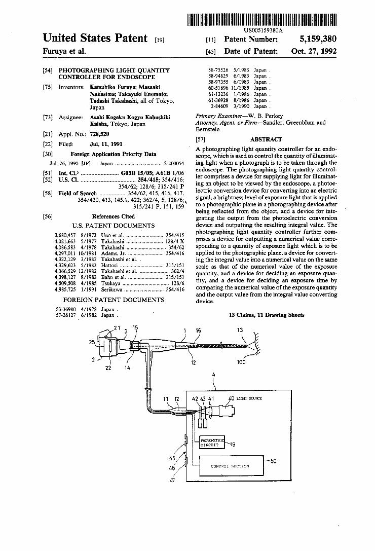
[57] ABSTRACT A photographing light quantity controller for an endo scope, which is used to control the quantity of illuminat ing light when a photograph is to be taken through the endoscope. The photographing light quantity control ler comprises a device for supplying light for illuminat ing an object to be viewed by the endoscope, a photoe lectric conversion device for converting into an electric signal, a brightness level of exposure light that is applied to a photographic plane in a photographing device after being re?ected from the object, and a device for inte ‘grating the output from the photoelectric conversion device and outputting the resulting integral value. The photographing light quantity controller further com prises a device for outputting a numerical value corre sponding to a quantity of exposure light which is to be applied to the photographic plane, a device for convert ing the integral value into a numerical value on the same scale as that of the numerical value of the exposure quantity, and a device for deciding an exposure quan tity, and a device for deciding an exposure time by comparing the numerical value of the exposure quantity and the output value from the integral value converting device.
13 Claims, 11 Drawing Sheets
CIRCUIT \lQ
CONTROL SECTION
US. Patent Oct. 27, 1992 Sheet 1 of 11 5,159,380
0
“I” z o H
1
E 92 w / ._-: v 2 E 1-1 a 2 1-1 O
E: 0 0 O: H
u
F/G.7
22
25
US. Patent Oct. 27, 1992 Sheet 3 of 11 5,159,380
m: c .w o .v o .m o A on .0 mm .o m: .o moo .o
mozwm?mm .ézo?zgzoo H
> 2.3550
28 £2 E m8 3 E S E w @582 @2828
and; $54.55
. N n N N N _ N N _ - N T N 7 N T N 3:248 mmswomxm
US. Patent Oct. 27, 1992 Sheet 4 of 11 5,159,380
H> 2.5256
£8 K9 Na wmN my EU NW 2 w 2525 5.5528 N w w w 9 N_ S 2 w_ 555 mmamomxm
5:5; mie?mm v
v N n N N N _ N H TN N- N T N T N wepzgo mmamomxm mmwI
US. Patent Oct.27,1992 Sheet 5 of 11 5,159,380
F/G.3C
OUTPUT VALUE
Vn INPUT VOLTAGE [voLT]
US. Patent Oct. 27, 1992 Sheet 7 of 11 5,159,380
F/G.5
VIR ------------- -
F/G.6
VIR ------------- —
v11
US. Patent Oct. 27, 1992 Sheet 8 of 11 5,159,380
FIG]
c ) CLOSE LIGHT SOURCE SHUTTER
52\ CALCULATE 2:1" CALCULATE EXPOSURE TIME T
53 > ’[ =T1 NO YES
S4\ OPEN LIGHT SOURCE SHUTTER
S5 tzT1+T N
Y \
S6 \ cLosE LIGHT SOURCE SHUTTER
S7
?g T2 N Y
OPEN LIGHT SOURCE SHUTTER
< RETURN >
US. Patent 0a. 27, 1992 Sheet 9 of 11 5,159,380
F/G. 8
sTART
S] I _cLosE LIGHT'soURcE SHUTTER
S12
S13 \ OPEN LIGHT soURcE
SHUTTER
514\ CALCULATE‘. __d_vl dt
CALCULATE EXPOSURE TIME T
_
S15 ‘
t2T1+T N
Y 516 \ cLosE LIGHT SOURCE J
SHUTTER
517 >T t- 2 N
Y
518 7 OPEN LIGHT soURcE
SHUTTER
v
< RE TU RN >
US. Patent Oct. 27, 1992 Sheet 10 of 11 5,159,380
F/ G. 9
VT
A / E‘VST
F/ G. 70
‘ff
AVIHT ------------------- _..|
......... ;
2W3"- : i O At1At2 At3 --— Atn
US. Patent 0a. 27, 1992 Sheet 11 of 11 5,159,380
F/G.77
dVT AVzT :C'2
dt At2
5,159,380 1
PHOTOGRAPHING LIGHT QUANTITY CONTROLLER FOR ENDOSCOPE
BACKGROUND OF THE INVENTION
The present disclosure relates to subject matter con tained in Japanese Patent application No. 2-200054 (?led on Jul. 26, 1990), which is expressly incorporated herein by reference in its entirety.
FIELD OF THE INVENTION The present invention relates to a photographing
light quantity controller for an endoscope, which is used to control the quantity of illuminating light when a photograph is to be taken through the endoscope. Endoscopes are generally designed to be capable of
not only observing the inside of a hollow organ in the patient’s body but also taking a photograph of it.
DESCRIPTION OF THE PRIOR ART
In a conventional photographing light quantity con troller for an endoscope, re?ected light from an object that is illuminated by a light source is received and converted into an electric signal with a light-receiving element. The output of the light-receiving element is integrated to obtain an integral value. When the integral value reaches a preset reference voltage, the application of the illuminating light to the object is stopped, thus effecting automatic control of the quantity of photo graphing light. To take a photograph through an endoscope, how
ever, it is necessary to enable photographing to be ef fected over a wide range of light exposure so that an optimum quantity of photographing light is obtained in conformity with the kind of endoscope used, the condi tion of a part which is photographed, and so forth. For this purpose, it is necessary to enlarge the range within which the reference voltage can be set. More specifi cally, the reference voltage must be capable of being set in a wide range, from a very low voltage to a high voltage, e.g., from 50 mV to 10V. ’
In order to enable the reference voltage to be set in such a wide range, however, hardware for generating a high voltage is needed only for producing a reference voltage. In addition, since the S/N ratio becomes low when a very low voltage is set as a reference voltage, hardware for coping with this problem is also needed. Consequently, the scale of the system enlarges, and the cost of the product increases.
SUMMARY OF THE INVENTION
An object of the present invention is to provide a photographing light quantity controller for an endo scope, which is capable of coping with a wide range of photographing conditions (i.e., light exposure) with simple and inexpensive hardware.
Other objects and advantages of the present invention will become apparent from the following detailed de scription of an illustrated embodiment of the invention. According to the present invention, there is provided
a photographing light quantity controller for an endo scope, which is used to control the quantity of illuminat ing light when a photograph is to be taken through the endoscope, comprising: a device for supplying light for illuminating an object to be viewed by the endoscope; a photoelectric conversion device for converting into an electric signal, a brightness level of exposure light that is applied to a photographic plane in a photographing
5
15
25
35
40
45
50
55
65
2 device after being reflected from the object; a device for integrating the output from the photoelectric conver sion device and outputting the resulting integral value; a device for outputting a numerical value correspond ing to a quantity of exposure light which is to be applied to the photographic plane; a device for converting the integral value into a numerical value on the same scale as that of the numerical value of the exposure quantity; and a device for deciding an exposure time by compar ing the numerical value of the exposure quantity and the output value from the integral value converting device.
In addition, there is provided a photographing light quantity controller for an endoscope, which is used to control the quantity of illuminating light when a photo graph is to be taken through the endoscope, comprising a device for supplying light for illuminating an object to the endoscope; a photoelectric conversion device for converting into an electric signal, a brightness level of exposure light that is applied to a photographic plane in a photographing device after being re?ected from the object; a device for integrating the output from the photoelectric conversion device and outputting the resulting integral value; a device for outputting a nu merical value corresponding to a quantity of exposure light which is to be applied to the photographic plane; a device for converting the integral value into a numeri cal value on the same scale as that of the numerical value of the exposure quantity; and a device for decid ing an exposure time by comparing the numerical value of the exposure quantity and the output value from the integral state value converting device, and controlling the period of time for supplying illuminating light to the endoscope from the light source on the basis of the exposure time calculated.
BRIEF DESCRIPTION OF THE DRAWINGS
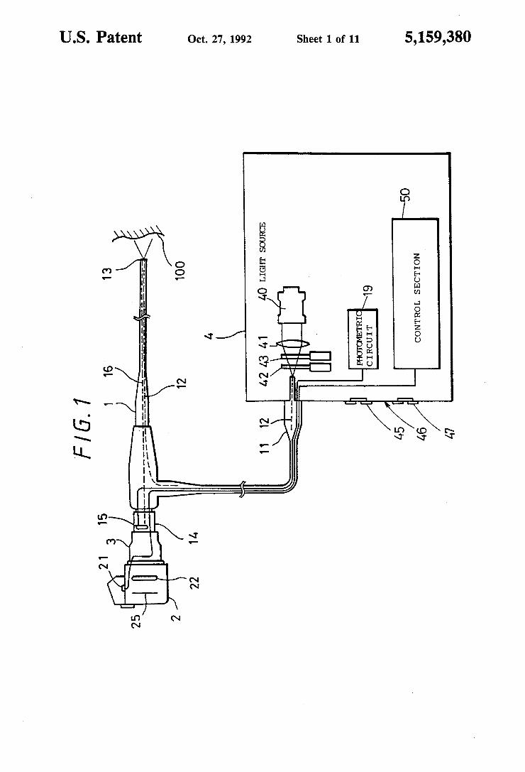
The present invention may be more fully understood from the description of a preferred embodiment of the invention set forth below, together with the accompa nying drawings, in which: FIG. 1 is a schematic view showing the whole ar
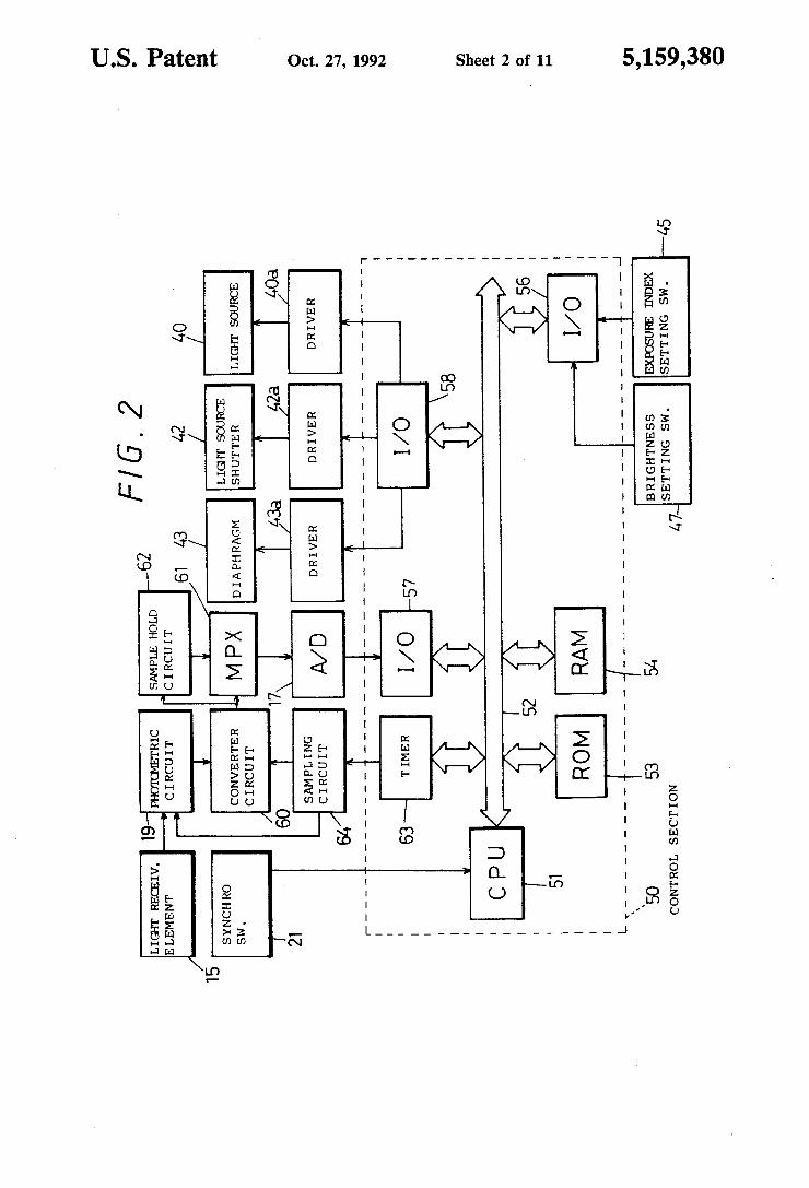
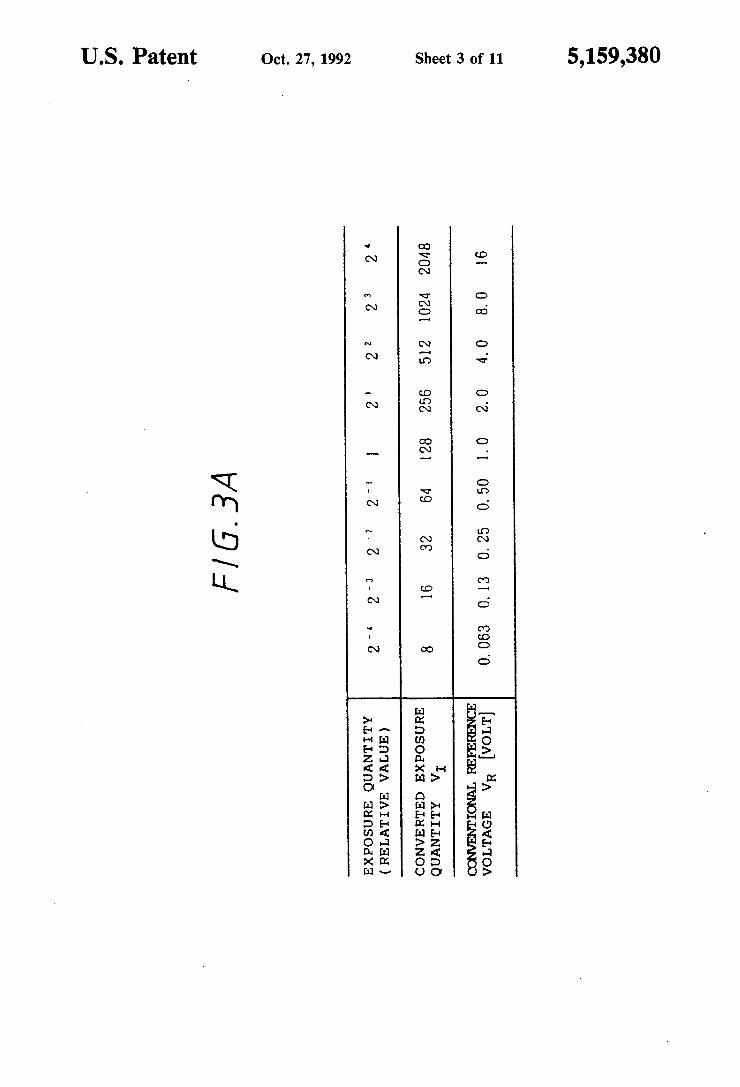
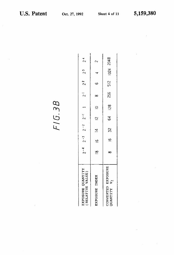
rangement of one embodiment of the present invention; FIG. 2 is a circuit block diagram of the embodiment; FIGS. 3A and 3B are charts exemplarily showing
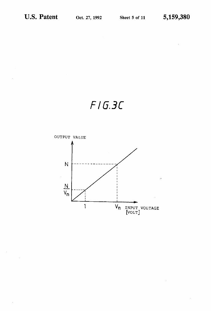
numerical values of the converted exposure quantity in the embodiment; FIG. 3C is a reference drawing for explanation of the
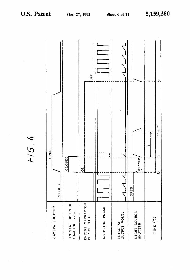
characteristics of a converter circuit in the embodiment; FIG. 4 is a time chart showing the operation of the
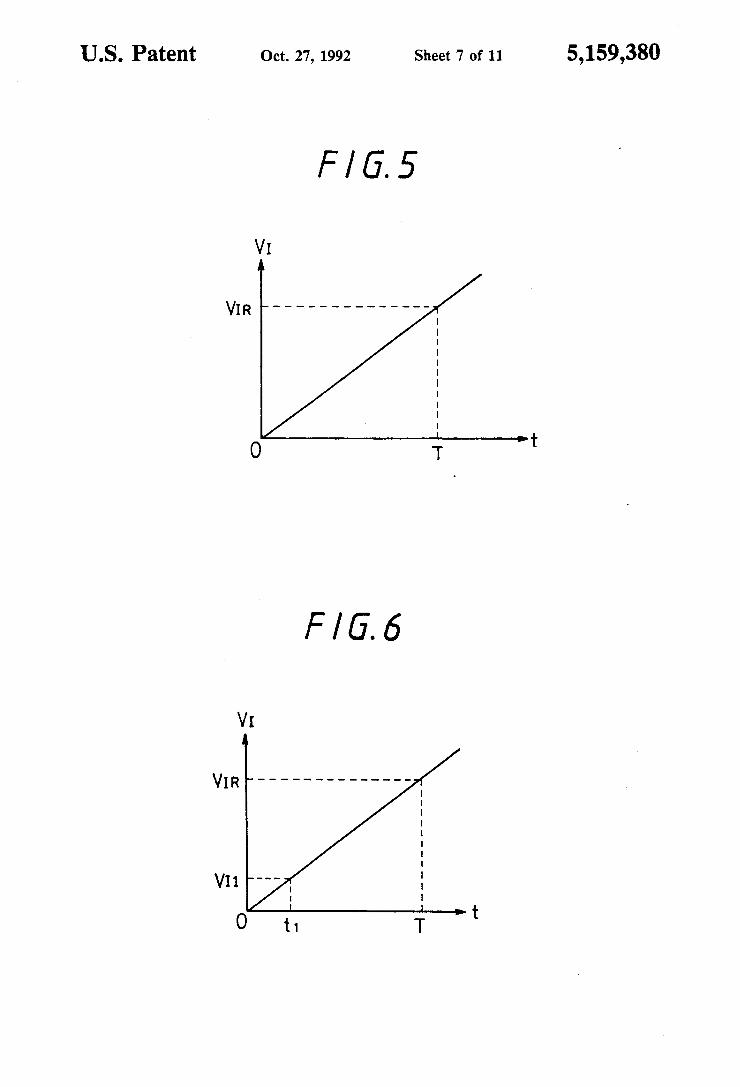
embodiment; FIGS. 5 and 6 are graphs showing the way of obtain
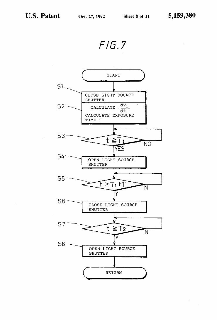
ing the exposure time T in the embodiment; FIGS. 7 and 8 are flowcharts each showing a control
process in the embodiment; FIGS. 9 and 10 are graphs showing the way of ob
taining a rate of change of VTper unit time in the em bodiment; and FIG. 11 is a flowchart showing an operation of ob
taining a rate of change of VTper unit time in the em bodiment.
DESCRIPTION OF THE EMBODIMENTS
Referring to FIG. 1, which shows the whole arrange ment of one embodiment of the present invention, refer ence numeral 1 denotes an endoscope. A camera (pho tographing device) 2 is detachably attached to an eye
5,159,380 3
piece 14 of the endoscope 1 through a photographic adapter 3.
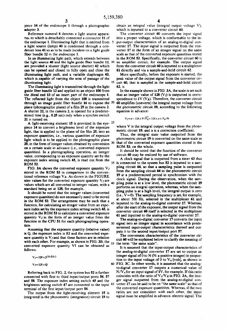
Reference numeral 4 denotes a light source appara tus, to which is detachably connected a connector 11 of the endoscope l. Illuminating light that is emitted from a light source (lamp) 40 is condensed through a con denser lens 41 so as to be made incident on a light guide ?ber bundle 12 in the endoscope 1.
In an illuminating light path, which extends between the light source 40 and the light guide ?ber bundle 12, are provided a shutter (light source shutter) 42 which can be opened and closed to fully open and close the illuminating light path, and a variable diaphragm 43, which is capable of varying the area of passage of the illuminating light. The illuminating light is transmitted through the light
guide ?ber bundle 12 and applied to an object 100 from the distal end 13 of an insert part of the endoscope 1. The re?ected light from the object 100 is transmitted through an image guide ?ber bundle 16 to expose the plane (photographic plane) of a ?lm 25 in the camera 2. A shutter 22, in the camera 2, is opened for a predeter mined time (e.g., 0.25 sec) only when a synchro switch 21 is turned on. A light-receiving element 15 is provided in the eye
piece 14 to convert a brightness level of the exposure light, that is applied to the plane of the ?lm 25, into an exposure quantities, i.e., various quantities of exposure
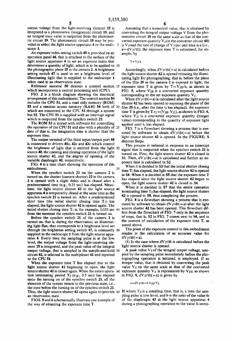
> light which is to be applied to the photographic plane 25, in the form of integer values obtained by conversion on a certain scale in advance (i.e., converted exposure quantities). In a photographing operation, an integer value, corresponding to an exposure quantity set by the exposure index setting switch 45, is read out from the ROM 53. FIG. 3A shows the converted exposure quantity V1
stored in the ROM 53 in comparison to the conven tional reference voltage VR. As shown in the FIGURE nine values for the converted exposure quantity V] are values which are all converted to integer values, with a standard being set at 128, for example.
It should be noted that the integer values (converted exposure quantities) do not necessarily need to be stored in the ROM 53. The arrangement may be such that a function, for calculating an integer value from an expo sure index set by the exposure index setting switch 45, is stored in the ROM 53 to calculate a converted exposure quantity V1 in the form of an integer value from the function in the CPU 51 for each photographing opera tion. Assuming that the exposure quantity (relative value)
is Q, the exposure index is El and the converted expo sure quantity is V] and that these factors are in relation with each other. For example, as shown in FIG. 3B, the converted exposure quantity VI can be obtained as follows:
Referring back to FIG. 2, the system bus 52 is further connected with ?rst to third input/output ports 56, 57 and 58. The exposure index setting switch 45 and the brightness setting switch 47 are connected to the input terminal of the ?rst input/output port 56. The output from the light-receiving element 15 is
integrated in the photometric (integration) circuit 19 to
5
15
20
25
35
45
50
4 obtain an integral value (integral output voltage V), which is inputted to a converter circuit 60. The converter circuit 60 converts the input signal
into a proper voltage, which is conformable to the in put-output characteristics of an analog-to-digital con verter 17. The input signal is outputted from the con verter 17 in the formof an integer signal on the same scale as that of the converted exposure quantities stored in the ROM 53. Speci?cally, the converter circuit 60 is an ampli?er circuit, for example. The output signal from the converter circuit 60 is inputted to a multiplexer 61 directly and via a sample-and-hold circuit 62. More speci?cally, before the exposure is started, the
peak value of the output signal from the converter cir cuit 60, that is sampled in the sample-and-hold circuit 62, is
In the example shown in FIG. 3A, the scale is set such that an integer value of 128 (V1) is outputted in corre spondence to 1V (V R). Therefore, the converter circuit 60 ampli?es (converts) the integral output voltage from the photometric circuit 19, according to the following equation in advance:
where V is the integral output voltage from the photo metric circuit 19, and a is a correction coefficient.
Thus, the integral state value outputted from the photometric circuit 19 is converted on the same scale as that of the converted exposure quantities stored in the ROM 53, on the whole.
It should be noted that the function of the converter circuit 60 may be realized by use of software. A clock signal that is outputted from a timer 63 that
is connected to the system bus 52 is inputted to a sam pling circuit 64, so that a sampling pulse is outputted from the sampling circuit 64 to the photometric circuit 19 at a predetermined period in synchronism with the clock signal. During the observation, when the sam pling pulse is at a low level, the photometric circuit 19 performs an integral operation, whereas, when the sam pling pulse is at a high level, the integral output is zero (i.e., V=0). The sampling frequency is set, for example, at about 500 Hz, selected in the multiplexer 61 and inputted to the analog-to-digital conveter 17. Whereas, after the start of the exposure, the output signal from the converter circuit 60 itself is selected in the multiplexer 61 and inputted to the analog-to-digital converter 17. The analog-to-digital converter 17 converts the input
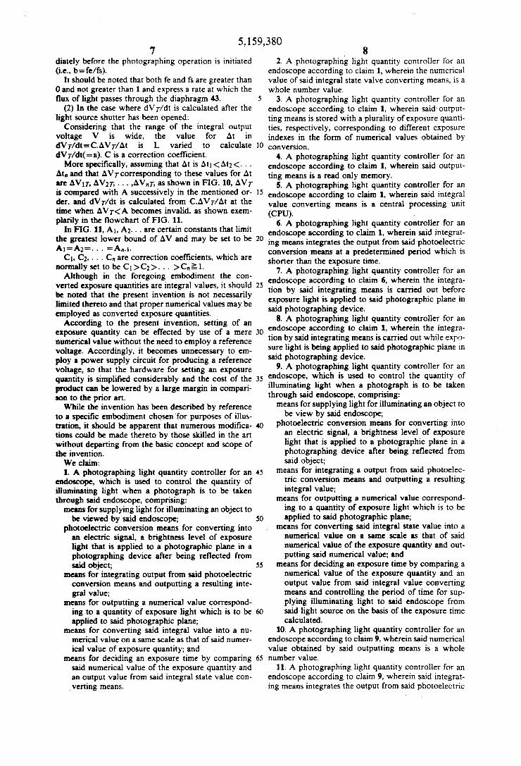
signal into an integer signal in accordance with prede termined input-output characteristics thereof and out puts it to the second input/output port 57. The conversion characteristics of the converter cir
cuit 60 will be explained below to clarify the meaning of the term "the same scale".
It is assumed that the input-output characteristics of the analog-todigital converter 17 are set to output an integer signal of 0 to N (N: a positive integer) in propor tion to the input voltage of 0 to V” [volt], as shown in FIG. 3C. In other words, it is assumed that the analog to-digital converter 17 outputs a numerical value of N/Vn for an input signal of 1V, for example. If this ratio coincides with the ratio of V//\’ R in FIG. 3A, the inte ger signal outputted from the analog-to-digital con verter 17 can be said to be on “the same scale" as that of the converted exposure quantitites. Whereas, if the two ratios are not coincident with each other, the input signal must be ampli?ed in advance. electric signal. The
5,159,380 5
output voltage from the light-receiving element 15 is integrated in a photometric (integration) circuit 19, and an integral state value is outputted from the photomet ric circuit 19. The photometric circuit 19 may be pro vided in either the light source apparatus 4 or the endo scope 1. .
An exposure index setting switch 45 is provided on an operation panel 46, that is attached to the surface of the light source apparatus 4 to set an exposure index that determines a quantity of light, which is to be applied to the photographic plane 25 in the camera 2. A brightness setting switch 47 is used to set a brightness level of illuminating light that is supplied to the endoscope 1 when used in an observation state.
Reference numeral 50 denotes a control section which incorporates a central processing unit (CPU). FIG. 2 is a block diagram showing the electrical
arrangement of this embodiment. The control section 50 includes the CPU 51, and a read only memory (ROM) 53 and a random access memory (RAM) 54 both of which are connected to the CPU 51 through a system bus 52. The CPU 51 is supplied with an interrupt signal which is outputted from the synchro switch 21. The ROM 53 is stored with software for controlling
the operation of the CPU 51 and also with a plurality of data of that is, the integration time is shorter than the exposure time. The output terminal of the third input/ output port 58
is connected to drivers 40a, 42a and 43a which control the brightness of light that is emitted from the light source 40, the opening and closing operation of the light source shutter 42, and the degree of opening of the variable diaphragm 43, respectively.
‘ FIG. 4 is a time chart showing the operation of this embodiment. When the synchro switch 21 on the camera 2 is
turned on, the shutter (camera shutter) 22 in the camera 2 is opened with a slight delay and is closed after a predetermined time (e.g., 0.25 sec) has elapsed. Mean time, the light source shutter 42 in the light source apparatus 4 is temporarily closed at the same time as the synchro switch 21 is turned on. After a predetermined short time (the initial shutter closing time T1) has elapsed, the light source shutter 42 is opened again. The initial shutter closing time T1 is, for example, 0.035 see from the moment the synchro switch 21 is turned on.
Before the synchro switch 21 of the camera 2 is turned on, that is, during the observation, an illuminat ing light ?ux, that corresponds to a brightness level set through the brightness setting switch 47, is constantly supplied to the endoscope 1 from the light source appa ratus 4. Every time the sampling pulse is at the low level, the output voltage from the light-receiving ele ment 15 is integrated, and the peak value of the integral output voltage, that is sampled in the sample-and-hold circuit 62, is selected in the multiplexer 61 and inputted to the CPU 51. When the exposure time T has elapsed due to the
light source shutter 42 beginning to open, the light source shutter 42 is closed again. When the entire opera tion terminating period T; (e.g., 0.5 sec) has elapsed since the turning on of the synchro switch 21, all the elements of the system return to the previous state, i.e., the state before the turning on of the synchro switch 21. Thus, the light source shutter 42 opens again to provide an observation state. FIGS. 5 and 6 schematically illustrate one example of
the way of obtaining the exposure time T.
0
5
20
35
40
45
60
65
6 Assuming that a ‘numerical value, that is obtained by
converting the integral output voltage V from the pho tometric circuit 19 on the same scale as that of the con verted exposure quantity V1 (in the converter circuit 60) is VTand the rate of change ofVTper unit time is a (i,e., a=dVT/dt), the exposure time T is calculated; for ex ample, by
Accordingly, when dV T/dt(=a) is calculated before the light source shutter 42 is opened releasing the illumi nating light for photographing, that is, before the plane of the ?lm 25 in the camera 2 is exposed to light, the exposure time T is given by T=V1R/a, as shown in FIG. 5, where VIR is a converted exposure quantity corresponding to the set exposure quantity V1. When dV T/dt(=a) is calculated after the light source
shutter 42 has been opened to exposing the plane of the ?lm 25 (i.e., after the time t1 has elapsed), the exposure time T is given by T-t1=(V1R-V11), as shown in FIG. 6, where V11 is a converted exposure quantity (integer value) corresponding to the quantity of exposure light applied until t1 has elapsed. FIG. 7 is a ?owchart showing a process that is exe
cuted by software to obtain dVr/dt(=a) before the light source shutter 42 is opened. In the FIGURE, S denotes Steps.
This process is initiated in response to an interrupt signal that is outputted when the synchro switch 21 is turned on. First, the light source shutter 42 is closed in S1. Then, dV T/dt(=a) is calculated and further an ex posure time is calculated in S2. When it is decided in S3 that the initial shutter closing
time T1 has elapsed, the light source shutter 42 is opened in S4. When it is decided in S5 that the exposure time T has elapsed since the light source shutter 42 began to open, the light source shutter 42 is closed in S6. When it is decided in S7 that the entire operation
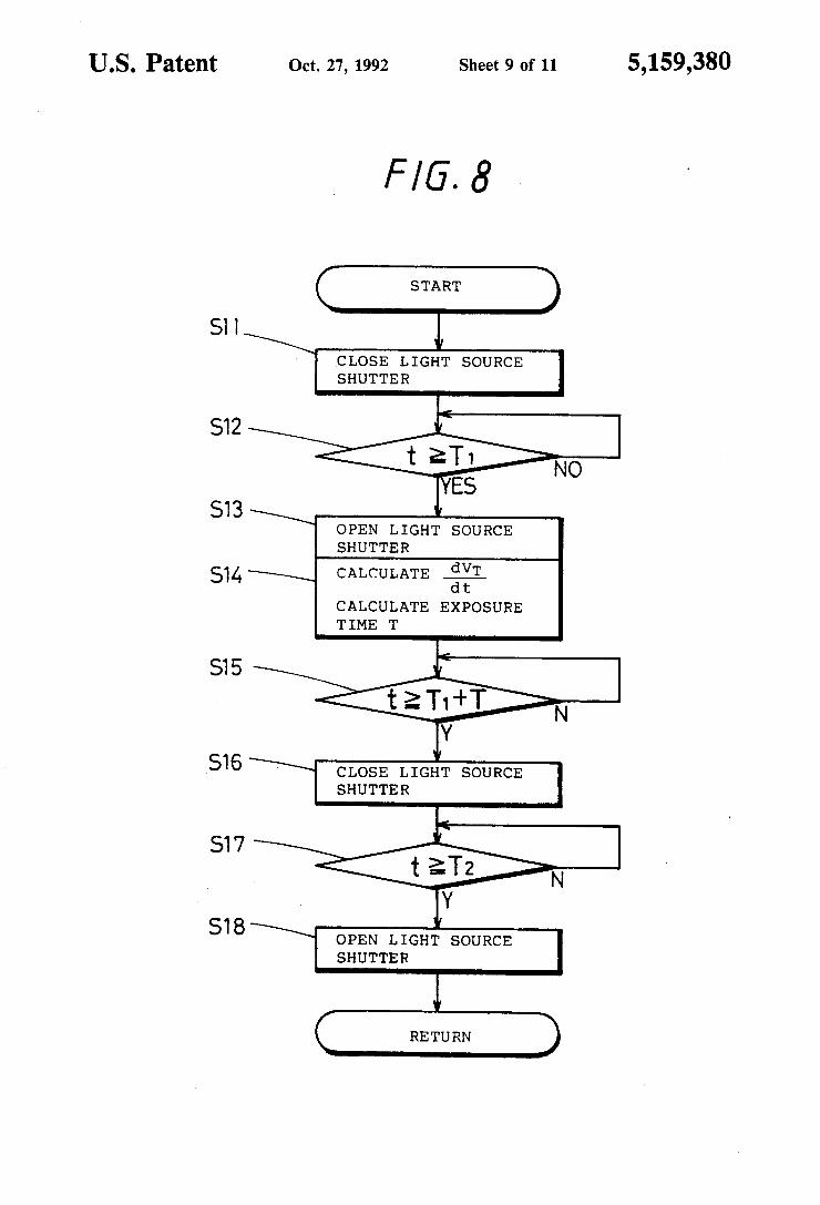
terminating time T; has elapsed, the light source shutter 42 is opened in S8, thus completing the process. FIG. 8 is a flowchart showing a process that is exe
cuted by software to obtain dVT/dt(=a) after the light source shutter 42 has been opened. This ?owchart dif fers from the ?owchart of FIG. 7 only in the sequence of steps, that is, $2 in FIG. 7 comes next to S4, and in the content of calculation of the exposure time T, as stated above. The point of the exposure control in this embodiment
resides in the calculation of an accurate value for dVT/dt(=a).
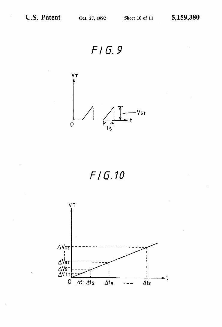
(1) In the case where dVT/dt is calculated before the light source shutter is opened: A peak value V5 of the integral output voltage, sam
pled by the sampling pulse immediately before the pho tographing operation is initiated, is employed. If an integer value, that is obtained by converting the peak value V5 on the same scale as that of the converted exposure quantity V1, is represented by VST, as shown in FIG. 9, dVT/dt(=a) is given by
H where T5 is a sampling time, that is, a time the sam pling pulse is low level, and b is the ratio of the value fe of the diaphragm 43 in the light source apparatus 4 during a photographing operation to the value fs imme
5,159,380 7
diately before the photographing operation is initiated (i.e., b=fe/fs).
It should be noted that both fe and fs are greater than 0 and not greater than 1 and express a rate at which the ?ux of light passes through the diaphragm 43.
(2) In the case where dVT/dt is calculated after the light source shutter has been opened:
Considering that the range of the integral output voltage V is wide, the value for At in dVr/dt=C.AVT/At is L varied to calculate dVT/dt(=a). C is a correction coef?cient. More speci?cally, assuming that At is At1<At2<. . .
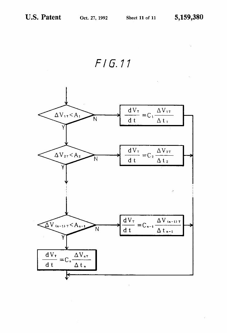
At, and that AVT corresponding to these values for At are AV1T, AVZT, . . . ,AVnT, as shown in FIG. 10, AVT is compared with A successively in the mentioned or der, and dVr/dt is calculated from C.AV7~/At at the time when AVT<A becomes invalid, as shown exem plarily in the ?owchart of FIG. 11.
In FIG. 11, A1, A2. . . are certain constants that limit the greatest lower bound of AV and may be set to be A1=A2=. . . =A,,.1.
C1, C2, . . . C” are correction coefficients, which are
normally set to be C1>C1>...>C,,§1. Although in the foregoing embodiment the con
vened exposure quantities are integral values, it should be noted that the present invention is not necessarily limited thereto and that proper numerical values may be employed as converted exposure quantities. According to the present invention, setting of an
exposure quantity can be effected by use of a mere numerical value without the need to employ a reference voltage. Accordingly, it becomes unnecessary to em ploy a power supply circuit for producing a reference voltage, so that the hardware for setting an exposure quantity is simpli?ed considerably and the cost of the product can be lowered by a large margin in compari son to the prior art. While the invention has been described by reference
to a speci?c embodiment chosen ‘for purposes of illus tration, it should be apparent that numerous modi?ca tions could be made thereto by those skilled in the art without departing from the basic concept and scope of the invention. We claim: 1. A photographing light quantity controller for an
endoscope, which is used to control the quantity of illuminating light when a photograph is to be taken through said endoscope, comprising: means for supplying light for illuminating an object to
be viewed by said endoscope; photoelectric conversion means for converting into
an electric signal, a brightness level of exposure light that is applied to a photographic plane in a photographing device after being reflected from said object;
means for integrating output from said photoelectric conversion means and outputting a resulting inte gral value;
means for outputting a numerical value correspond ing to a quantity of exposure light which is to be applied to said photographic plane;
means for converting said integral value into a nu merical value on a same scale as that of said numer ical value of exposure quantity; and
means for deciding an exposure time by comparing said numerical value of the exposure quantity and an output value from said integral state value con verting means.
15
20
40
45
50
55
8 2. A photographing light quantity controller for an
endoscope according to claim 1, wherein the numerical value of said integral state valve converting means, is a whole number value.
3. A photographing light quantity controller for an endoscope according to claim 1, wherein said' output ting means is stored with a plurality of exposure quanti ties, respectively, corresponding to different exposure indexes in the form of numerical values obtained by conversion.
4. A photographing light quantity controller for an endoscope according to claim 1, wherein said output ting means is a read only memory.
5. A photographing light quantity controller for an endoscope according to claim 1, wherein said integral value converting means is a central processing unit (CPU). ,
6. A photographing light quantity controller for an endoscope according to claim 1, wherein said integrat ing means integrates the output from said photoelectric conversion means at a predetermined period which is shorter than the exposure time.
7. A photographing light quantity controller for an endoscope according to claim 6, wherein the integra tion by said integrating means is carried out before exposure light is applied to said photographic plane in said photographing device.
8. A photographing light quantity controller for an endoscope according to claim 1, wherein the integra tion by said integrating means is carried out while expo sure light is being applied to said photographic plane in said photographing device.
9. A photographing light quantity controller for an endoscope, which is used to control the quantity of illuminating light when a photograph is to be taken through said endoscope, comprising: means for supplying light for illuminating an object to
be view by said endoscope; photoelectric conversion means for converting into
an electric signal, a brightness level of exposure light that is applied to a photographic plane in a photographing device after being re?ected from said object;
means for integrating a output from said photoelec tric conversion means and outputting a resulting integral value;
means for outputting a numerical value correspond ing to a quantity of exposure light which is to be applied to said photographic plane;
means for converting said integral state value into a numerical value on a same scale as that of said numerical value of the exposure quantity and out putting said numerical value; and
means for deciding an exposure time by comparing a numerical value of the exposure quantity and an output value from said integral value converting means and controlling the period of time for sup plying illuminating light to said endoscope from said light source on the basis of the exposure time calculated.
10. A photographing light quantity controller for an endoscope according to claim 9, wherein said numerical value obtained by said outputting means is a whole number value.
11. A photographing light quantity controller for an endoscope according to claim 9, wherein said integrat ing means integrates the output from said photoelectric
5,159,380 9
conversion means at a predetermined period which is
shorter than the exposure time.
12. A photographing light quantity controller for an
endoscope according to claim 11, wherein the integra
tion by said integrating means is carried out before
5
1O
15
25
35
50
55
65
10 exposure light is applied to the photographic plane in said photographing device.
13. A photographing light quantity controller for an endoscope according to claim 9, wherein the integra tion by said integrating means is carried out while expo sure light is being applied to the photographic plane in said photographing device.
# i i i i

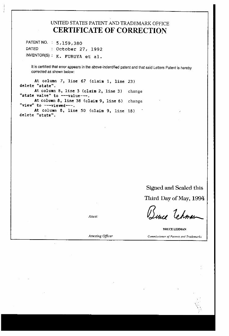
UNITED STATES PATENT AND TRADEMARK OFFICE
CERTIFICATE OF CORRECTION
PATENTNO. : 5,159,380
DATED : October 27, 1992
INVENTOR(S)I K. FURUYA et a1.
It is certified that error appears in the above-indentified patent and that said Letters Patent is hereby corrected as shown below:
At column 7, line 67 (claim 1, line 23) delete "state".
At column 8, line 3 (claim 2, line 3) change "state valve" to ———value———.
At column 8, line 38 (claim 9, line 6) change "view" to ——-viewed---. '
At column 8, line 50 (claim 9, line 18) _ delete "state".
Signed and Sealed this
Third Day of May, 1994
BRUCE LEHMAN
AIICSIing Oj?cer Commissioner of Patents and Trademarks