Embed Size (px)
Citation preview
Photogrammetry is the science and technology of taking spatial measurements from photographs and preparing geometrically reliable derivative products.
The techniques are based on the geometry of perspective scenes and on the principles of stereovision.
Two kinds of photographs used in photogrammetry: aerial and terrestrial.
Aerial photographs are usually acquired from aircraft but can also come from satellites, hot air balloons or even kites. Terrestrial photographs come from cameras based on the ground, and generally are used in different applications from aerial.
There are two main data extraction methods used for analysing these photographs:
a. Quantitative: that is size, length, shape, height, area, etc. b. Qualitative: geology, vegetation, drainage, land use, etc.
Historically, the most common use of photogrammetry was to produce hardcopy topographic maps, now it is used to produce a range of GIS data products such as DEMs, accurate raster images backdrops for vector data
Photogrammetry
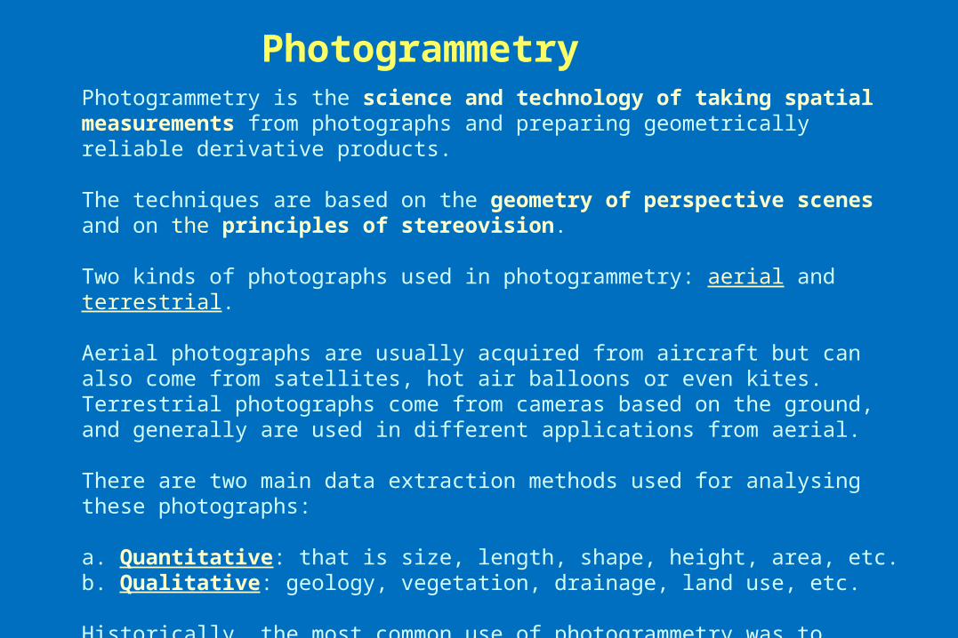
Aerial photographs
- Vertical - Oblique
Vertical photographs most commonly used, but true vertical photographs are rare because of the angular attitude of the aircraft at the time of photography.
This results in slight (1-3º) unintended inclination of the optic axis of the camera, resulting in titled photographs.
However, for most practical applications, such photographs can be considered vertical photographs.
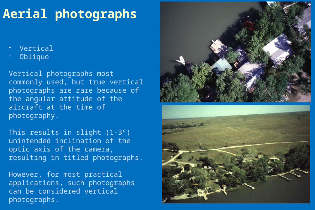
4-44-54-6
3-63-53-4
Block of Aerial Photography
Compiled into an Uncontrolled
Photomosaic
a.
b.
Aerial photographs
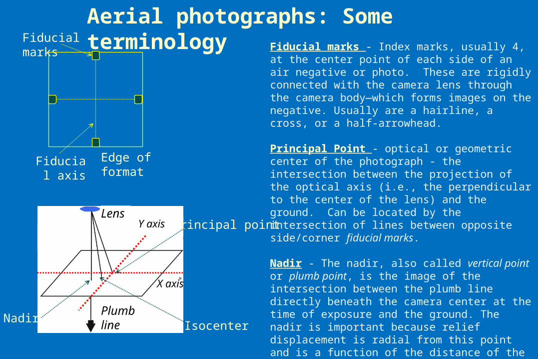
Aerial photographs: Some terminologyFiducial marks - Index marks, usually 4, at the center point of each side of an air negative or photo. These are rigidly connected with the camera lens through the camera body—which forms images on the negative. Usually are a hairline, a cross, or a half-arrowhead.
Principal Point - optical or geometric center of the photograph - the intersection between the projection of the optical axis (i.e., the perpendicular to the center of the lens) and the ground. Can be located by the intersection of lines between opposite side/corner fiducial marks.
Nadir - The nadir, also called vertical point or plumb point, is the image of the intersection between the plumb line directly beneath the camera center at the time of exposure and the ground. The nadir is important because relief displacement is radial from this point and is a function of the distance of the displaced image from it. Unlike the principal point, there are no marks on the photograph that permit to locate the nadir.
Isocenter - The point on the photo that falls on a line half- way between the principal point and the Nadir point.
Fiducial marks
Edge of format Fiducial axis
Lens
X axis
Plumb line
Principal point
NadirIsocenter
Y axis
Determination of nadir in oblique photos
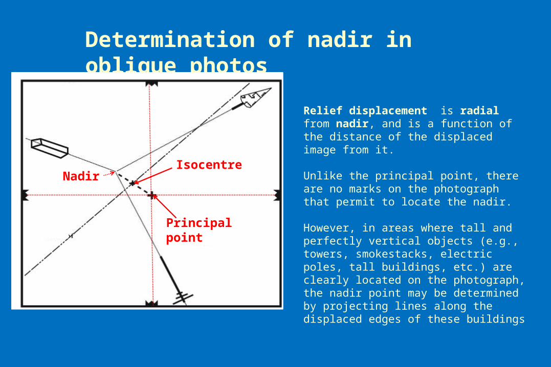
Relief displacement is radial from nadir, and is a function of the distance of the displaced image from it. Unlike the principal point, there are no marks on the photograph that permit to locate the nadir.
However, in areas where tall and perfectly vertical objects (e.g., towers, smokestacks, electric poles, tall buildings, etc.) are clearly located on the photograph, the nadir point may be determined by projecting lines along the displaced edges of these buildings
Principal point
NadirIsocentre
Jensen, 2000
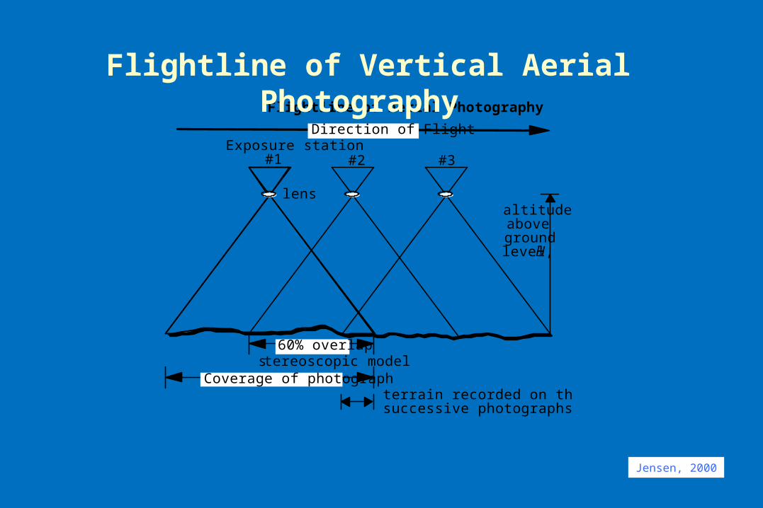
Exposure station #1
stereoscopic model
#2 #3
Direction of Flight
terrain recorded on three successive photographs
lens altitude above ground level, H
60% overlap
Coverage of photograph
Flightline of Aerial Photography
Flightline of Vertical Aerial Photography
20 – 30% sidelap
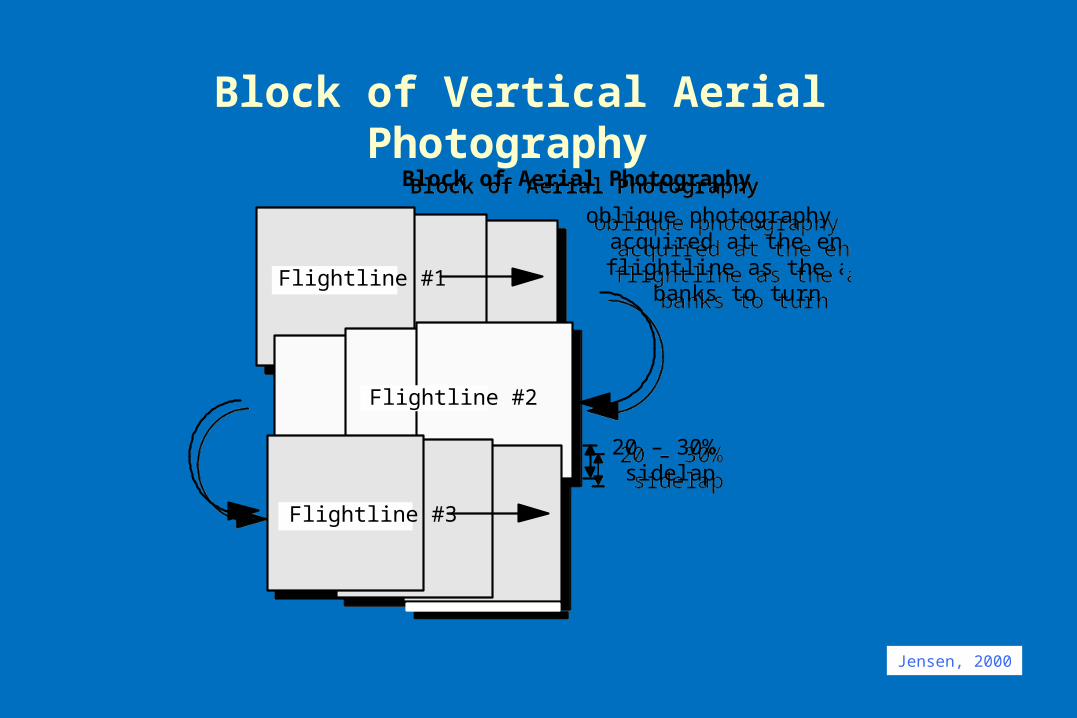
oblique photography may be acquired at the end of a flightline as the aircraft
banks to turn
Flightline #3
Flightline #2
Block of Aerial Photography
Flightline #1
20 – 30% sidelap
oblique photography may be acquired at the end of a flightline as the aircraft
banks to turn
Flightline #3
Flightline #2
Block of Aerial Photography
Flightline #1
Block of Vertical Aerial Photography
Jensen, 2000
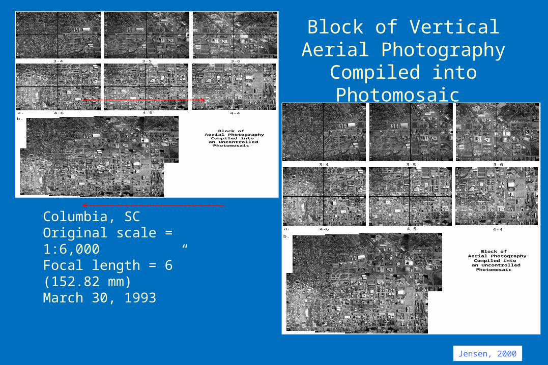
Block of Vertical Aerial Photography Compiled into
Photomosaic
Columbia, SCOriginal scale = 1:6,000Focal length = 6” (152.82 mm)March 30, 1993
Jensen, 2000
4-44-54-6
3-63-53-4
Block of Aerial Photography
Compiled into an Uncontrolled
Photomosaic
a.
b.
4-44-54-6
3-63-53-4
Block of Aerial Photography
Compiled into an Uncontrolled
Photomosaic
a.
b.
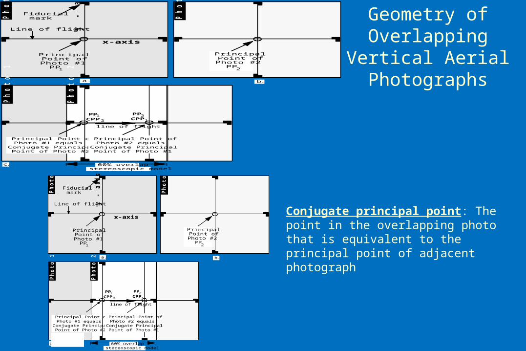
Geometry of Overlapping Vertical Aerial Photographs
Fiducial mark
y - a
xis
Line of flight
Principal Point of Photo #1
Ph
oto
1
Ph
oto
2
Principal Point of Photo #1 equals
Conjugate Principal Point of Photo #2
Principal Point of Photo #2 equals
Conjugate Principal Point of Photo #1
b.a.
c.
line of flight
stereoscopic model60% overlap
PP
CPP
PP
CPP
1
12
2
x-axis
Ph
oto
1
Ph
oto
2
PP1PP2
Principal Point of
Photo #2
Conjugate principal point: The point in the overlapping photo that is equivalent to the principal point of adjacent photograph
Fiducial mark
y -
ax
is
Line of flight
Principal Point of Photo #1
Ph
oto
1
Ph
oto
2
Principal Point of Photo #1 equals
Conjugate Principal Point of Photo #2
Principal Point of Photo #2 equals
Conjugate Principal Point of Photo #1
b.a.
c.
line of flight
stereoscopic model60% overlap
PP
CPP
PP
CPP
1
12
2
x-axis
Ph
oto
1
Ph
oto
2
PP1PP2
Principal Point of
Photo #2
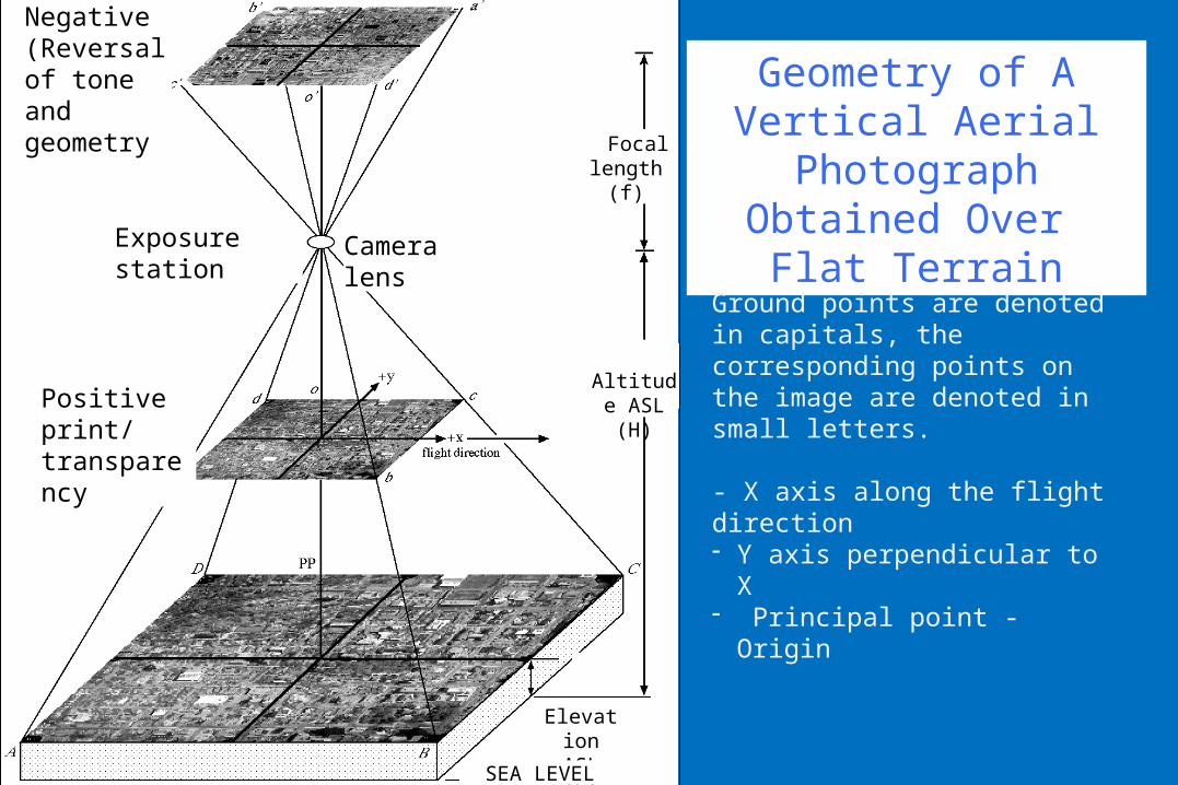
Geometry of A Vertical Aerial Photograph
Obtained Over Flat Terrain
Ground points are denoted in capitals, the corresponding points on the image are denoted in small letters.
- X axis along the flight direction - Y axis perpendicular to X- Principal point - Origin
Exposure station Camera lens
Positive print/ transparency
Focal length (f)
Altitude ASL (H)
Elevation ASL (h)
SEA LEVEL
Negative (Reversal of tone and geometry
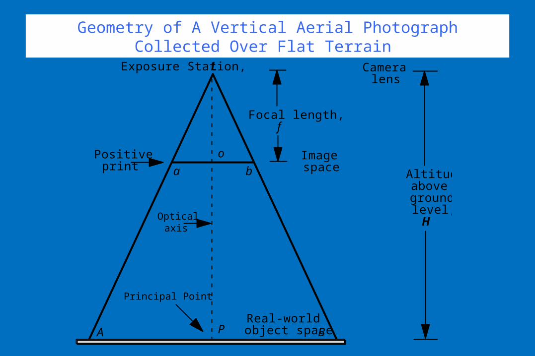
Geometry of A Vertical Aerial Photograph Collected Over Flat Terrain
Principal Point
Optical axis
Camera lens
Focal length, f
A B
a b
o
P
Positive print
Real-world object space
Image space
Altitude above ground level,
H
Exposure Station, L
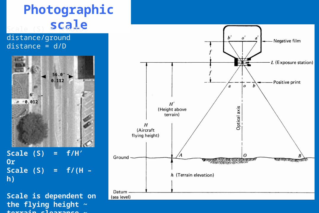
Photographic scale
Scale (S) = Photo distance/ground distance = d/D
Scale (S) = f/H′OrScale (S) = f/(H – h)
Scale is dependent on the flying height ~ terrain clearance ~ terrain elevation
56.0’
0.112”
6’
0.012”
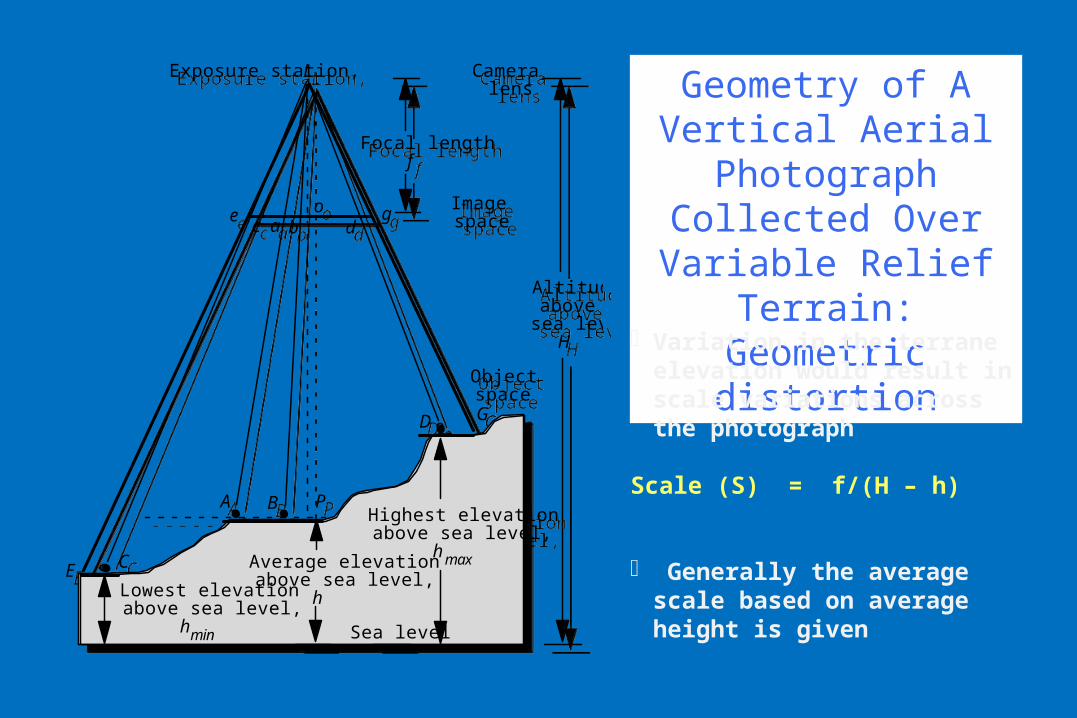
Geometry of A Vertical Aerial Photograph
Collected Over Variable Relief Terrain:
Geometric distortion
Average elevation above sea level,
h
Camera lens
Focal length f
Exposure station, L
A B
e go
P
Sea level
C
D
Highest elevation above sea level,
h max
Lowest elevation above sea level,
hmin
c d
Altitude above
sea level H
E
G
a bImage space
Object space
Average elevation above sea level,
h
Camera lens
Focal length f
Exposure station, L
A B
e go
P
Sea level
C
D
Highest elevation above sea level,
h max
Lowest elevation above sea level,
hmin
c d
Altitude above
sea level H
E
G
a bImage space
Object space
Þ Variation in the terrane elevation would result in scale variations across the photograph
Scale (S) = f/(H – h)
Þ Generally the average scale based on average height is given
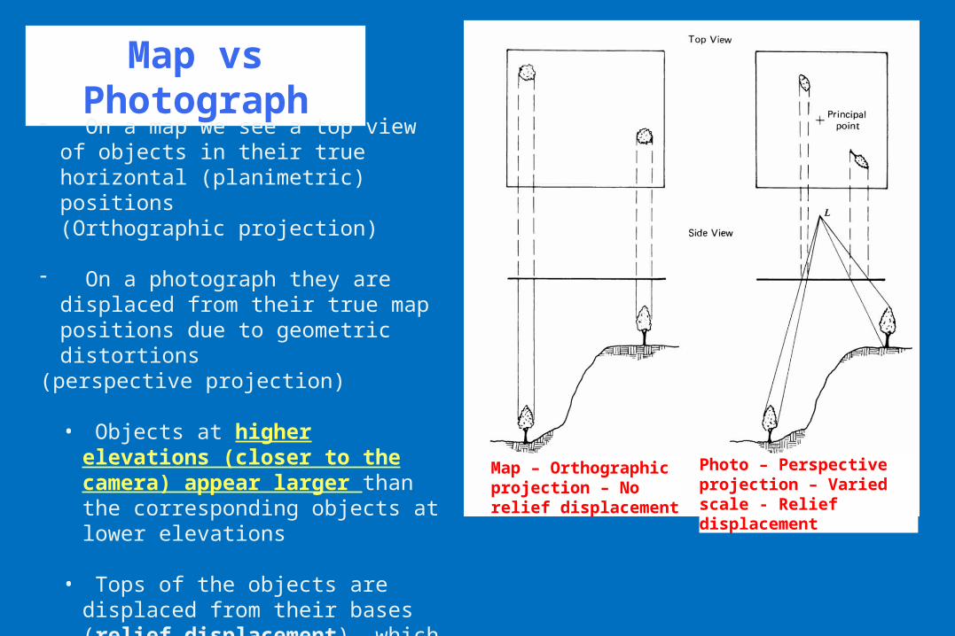
Map vs Photograph
- On a map we see a top view of objects in their true horizontal (planimetric) positions (Orthographic projection)
- On a photograph they are displaced from their true map positions due to geometric distortions
(perspective projection)
• Objects at higher elevations (closer to the camera) appear larger than the corresponding objects at lower elevations
• Tops of the objects are displaced from their bases (relief displacement), which causes any object standing above the terrain to “lean” away from the principal point.
Map – Orthographic projection – No relief displacement
Photo – Perspective projection – Varied scale - Relief displacement
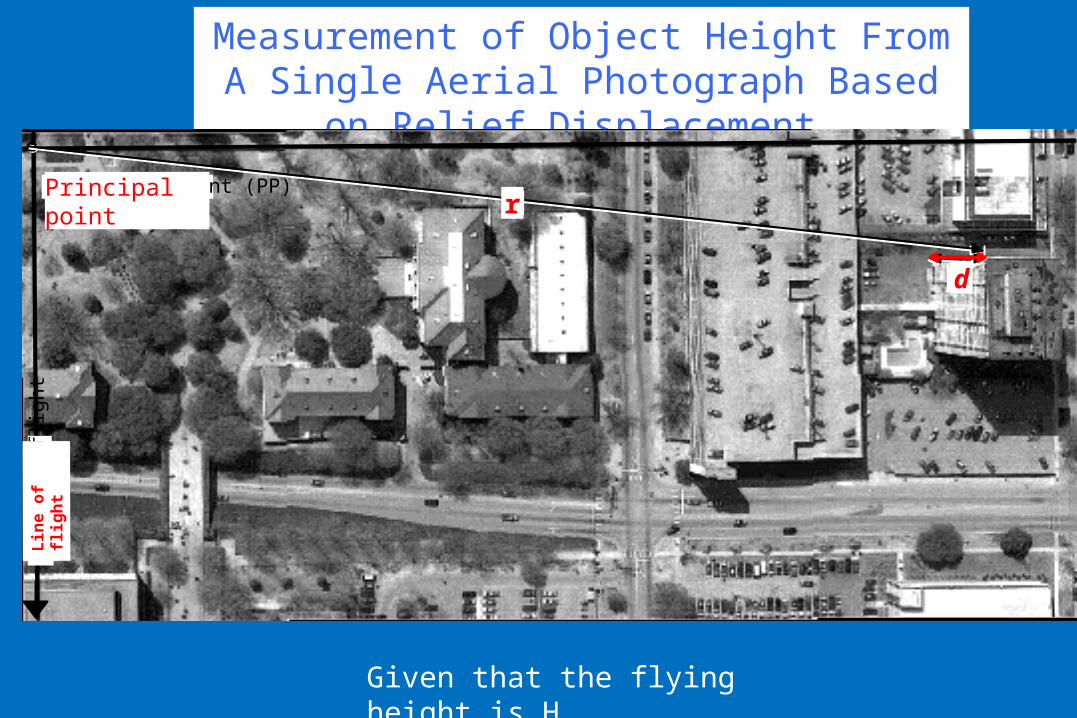
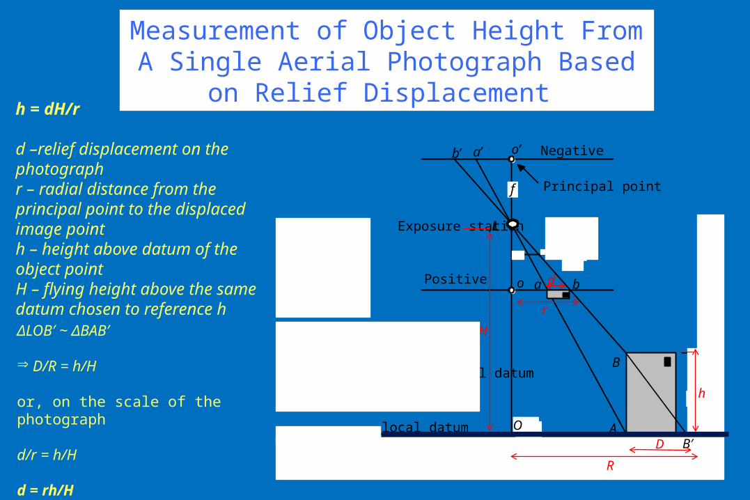
Measurement of Object Height From A Single Aerial Photograph Based on Relief Displacement
Principal point (PP)
d
Lin
e of
flig
ht
d
r
Lin
e of
fli
ght
r
d
Principal point
Given that the flying height is H
Measurement of Object Height From A Single Aerial Photograph Based on Relief Displacement
h = dH/r
d –relief displacement on the photographr – radial distance from the principal point to the displaced image pointh – height above datum of the object pointH – flying height above the same datum chosen to reference h
r
Negative
Exposure station, L
local datum
h
H
d r
H
=
d
h
h d
r =
H x
r = 2.23 in. d = 0.129 in. H = 2978.5 ft above local datum h = 172 ft
Principal point
Positive
f
A
B
a
b’
b
a’
o
o’
PP B′D
H
h
r
d
O
R
ΔLOB′ ~ ΔBAB′
Þ D/R = h/H
or, on the scale of the photograph
d/r = h/H
d = rh/H
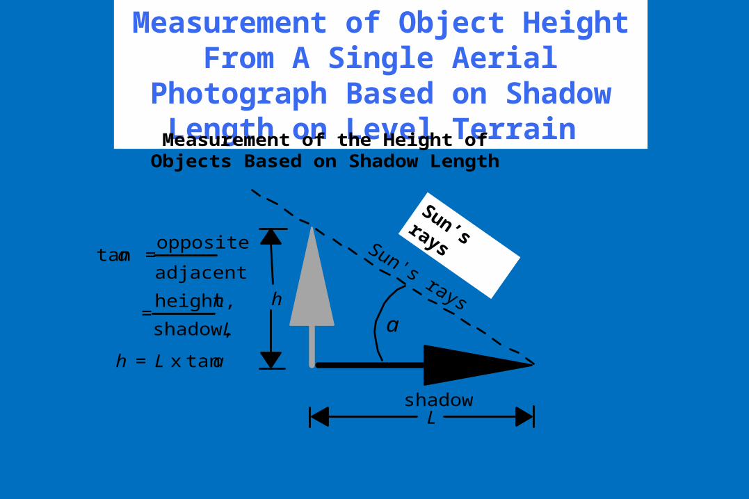
Measurement of Object Height From A Single Aerial Photograph Based on Shadow Length on Level Terrain
shadowL
Measurement of the Height of Objects Based on Shadow Length
h
a
tan a = adjacent
opposite
= shadow, L
height, h
h = L x tan a
Sun’s rays
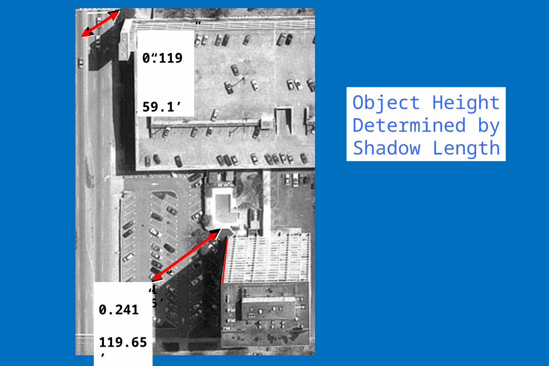
Object Height Determined by Shadow Length
0.119” 59.1’
0.241” 119.65’
0.119” 59.1’
0.241” 119.65’
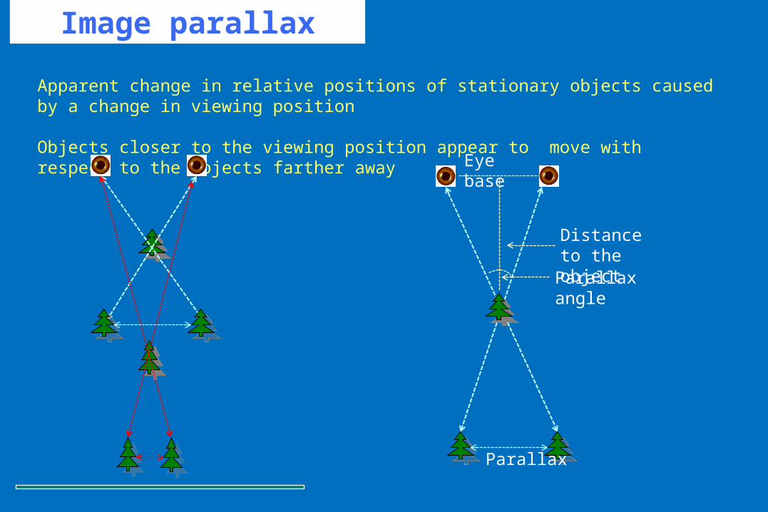
Image parallax
Apparent change in relative positions of stationary objects caused by a change in viewing position
Objects closer to the viewing position appear to move with respect to the objects farther away
Eye base
Distance to the object
Parallax angle
Parallax
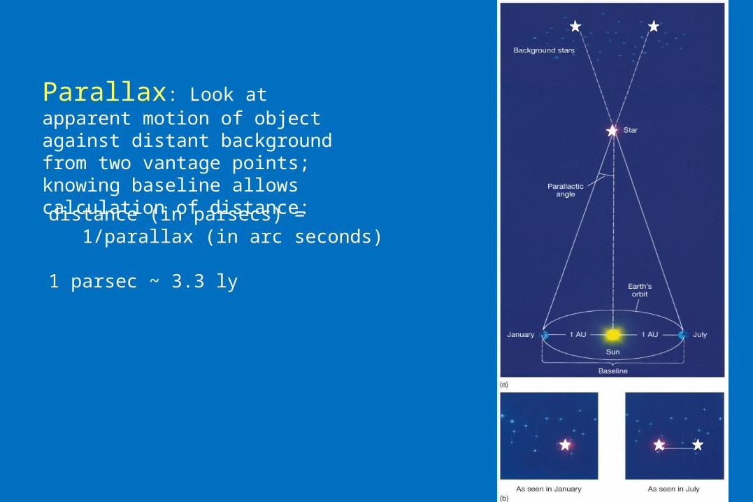
Parallax: Look at apparent motion of object against distant background from two vantage points; knowing baseline allows calculation of distance:
distance (in parsecs) = 1/parallax (in arc seconds)
1 parsec ~ 3.3 ly
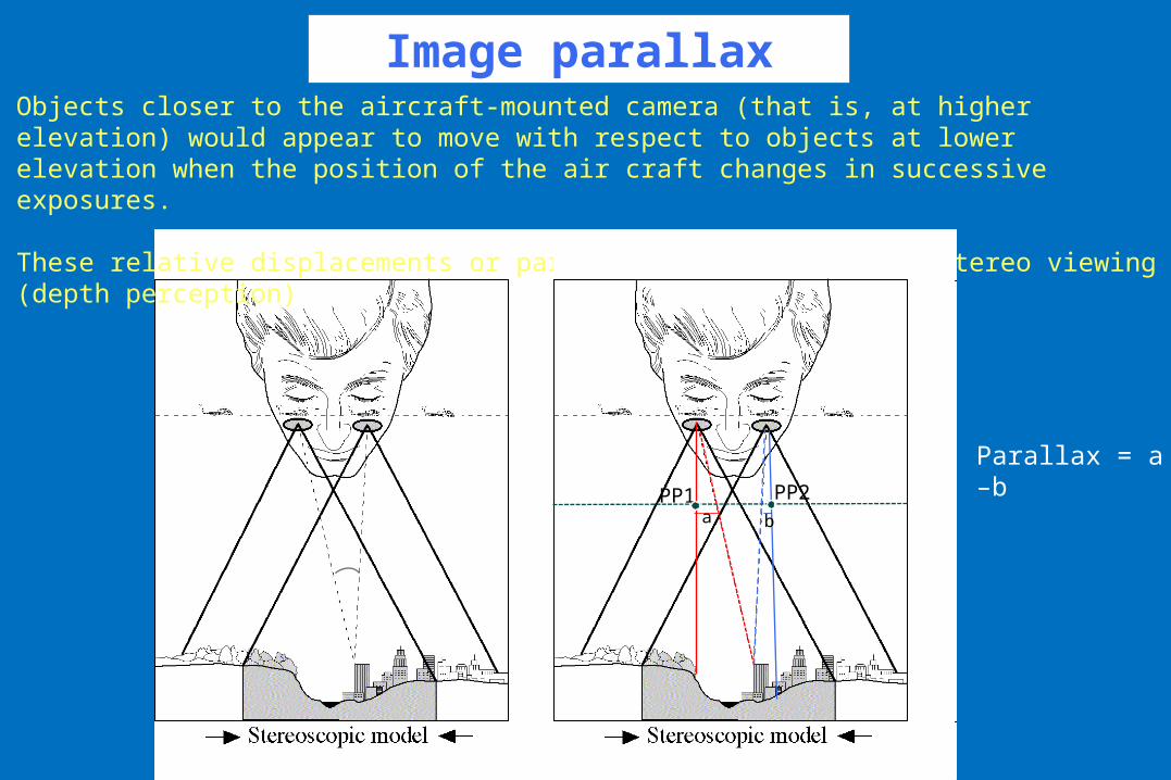
Image parallaxObjects closer to the aircraft-mounted camera (that is, at higher elevation) would appear to move with respect to objects at lower elevation when the position of the air craft changes in successive exposures.
These relative displacements or parallax form the basis of stereo viewing (depth perception)
PP1 PP2a b
Parallax = a –b
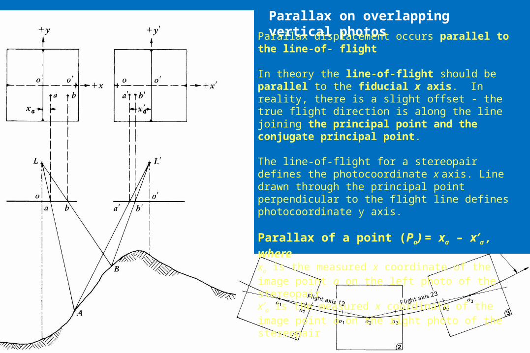
Parallax on overlapping vertical photos
Parallax displacement occurs parallel to the line-of- flight
In theory the line-of-flight should be parallel to the fiducial x axis. In reality, there is a slight offset - the true flight direction is along the line joining the principal point and the conjugate principal point.
The line-of-flight for a stereopair defines the photocoordinate x axis. Line drawn through the principal point perpendicular to the flight line defines photocoordinate y axis.
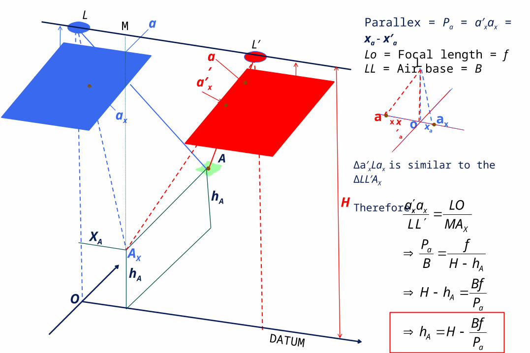
Parallax of a point (Pa) = xa – x′a , wherexa is the measured x coordinate of the image point a on the left photo of the stereopairx′a is the measured x coordinate of the image point a on the right photo of the stereopair
A
aL
xa
ax
o
fa′
a′x
o′x′a
f
hA
hA
XA
L′
O
AX
xa
axo
L
a′xo′x′a
L′
xa
axoa′x
x′a
L
DATUM
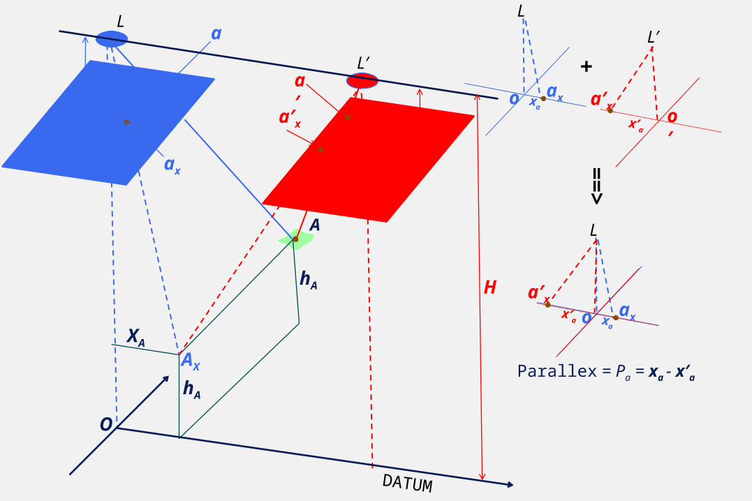
Parallex = Pa = xa - x′a
+
==
>
H
A
aL
xa
ax
o
fa′
a′x
o′x′a
f
hA
hA
XA
L′
O
AX
xa
axoa′x x′a
L
DATUM
Parallex = Pa = a′xax = xa - x′a
Lo = Focal length = fLL = Air base = B
H
Δa′xLax is similar to the ΔLL′AX
Therefore,
aA
aA
A
a
X
xx
P
BfHh
P
BfhH
hH
f
B
P
MA
LO
LL
aa
M
DATUM
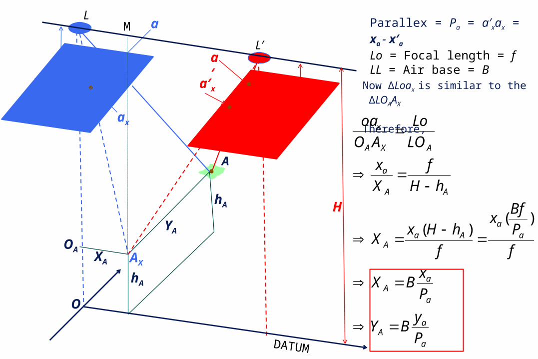
Parallex = Pa = a′xax = xa - x′a
Lo = Focal length = fLL = Air base = B
H
Now ΔLoax is similar to the ΔLOAAX
Therefore,
a
aA
a
aA
aa
AaA
AA
a
AXA
x
P
yBY
P
xBX
f
PBf
x
f
hHxX
hH
f
X
x
LO
Lo
AO
oa
)()(
M
OA
ya
A
aL
xa
ax
o
fa′
a′x
o′x′a
f
hA
hA
XA
L′
O
AX
YA
A
aL
xa
ax
o
fa′
a′x
o′x′a
f
hA
hA
XA
L′
O
AX
DATUM
H
a
a
aA
a
aA
aA
p
Hph
p
yBY
p
xBX
p
BfHh
M
OA
ya
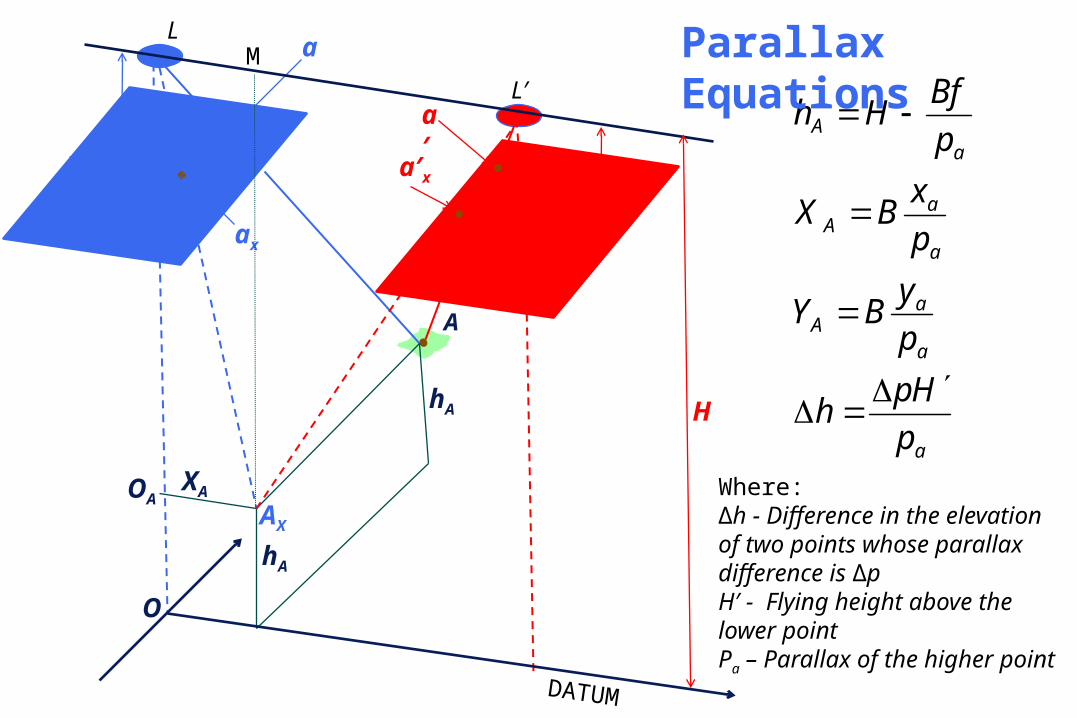
Parallax Equations
Where:Δh - Difference in the elevation of two points whose parallax difference is ΔpH′ - Flying height above the lower pointPa – Parallax of the higher point
x = - 0.267”
x = - 0.270”
Fid
ucial lin
e fro
m P
ho
to
4
-4
x = - 3.606”
x = - 3.82”
F
id
ucial lin
e fro
m P
ho
to
4
-5
p = 0.511”
p = 0.30”
c.
b.
c.
a.
Photo 4-5
Photo 4-4
Methods of Measuring Stereoscopic x-parallax from
Overlapping Aerial Photographs: • Measurement Using Fiducial Lines (a,b) • Measurement Based on Superposition (c)
Photo 4-5 Photo 4-4
dp = 0.211”
PP 4-5
PP 4-4
b’
a’
b
a
b
a
Principal point 4-5x axis
y ax
is
Principal point 4-4
'30.178"55.3
'3000"211.0
"211.0"339.3"55.3
"339.3)"606.3("267.0
"55.3)"82.3("27.0
'
'
a
b
a
x
bbx
aax
p
Hph
p
xxp
xxp
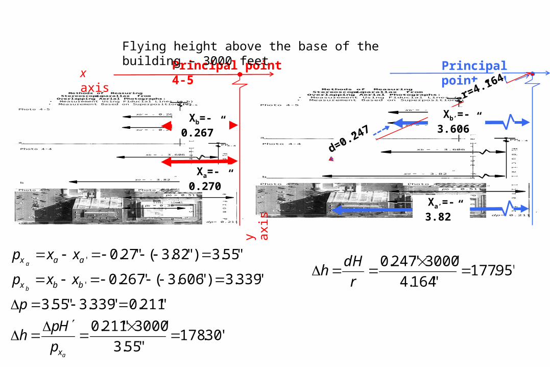
The height of the Senate Condominium in Columbia
d=0.247”
Xb’=-3.606”
Xa’=-3.82”
Xb=-0.267”
Xa=-0.270”
r=4.164”
'95.177"164.4
'3000"247.0
r
dHh
Flying height above the base of the building – 3000 feet
Parallax measurement
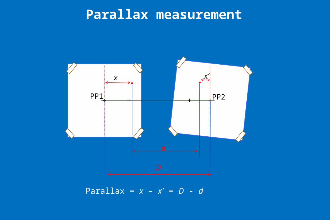
+ +++PP1 PP2
x x′
d
D
Parallax = x – x′ = D - d
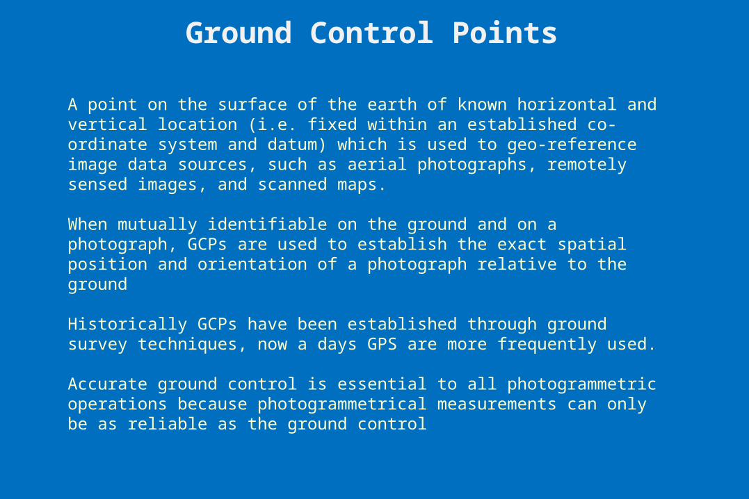
Ground Control Points
A point on the surface of the earth of known horizontal and vertical location (i.e. fixed within an established co-ordinate system and datum) which is used to geo-reference image data sources, such as aerial photographs, remotely sensed images, and scanned maps.
When mutually identifiable on the ground and on a photograph, GCPs are used to establish the exact spatial position and orientation of a photograph relative to the ground
Historically GCPs have been established through ground survey techniques, now a days GPS are more frequently used.
Accurate ground control is essential to all photogrammetric operations because photogrammetrical measurements can only be as reliable as the ground control
FLIGHT PLANNINGParameters:• Focal length of the camera to be used• The film format size• Photoscale desired• Size of the area to be photographed• Average elevation of the area to be photographed• The overlap desired• Side-lap desired• Ground speed of the aircraft
Based on the above parameters, mission planner decides:• The flying height above the datum• the location, direction, and the number of flight lines to be made• the time interval between exposures• the number of exposures on each flight line• the total number of exposures for the mission
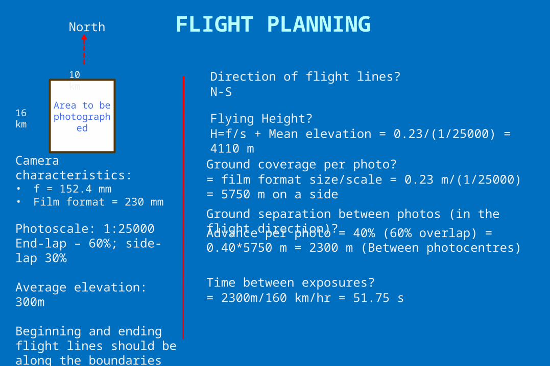
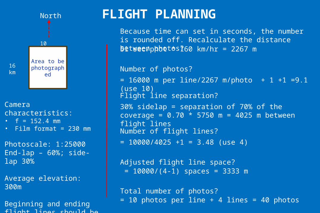
FLIGHT PLANNING
Area to be photographed
North
16 km
10 km
Camera characteristics:• f = 152.4 mm• Film format = 230 mm
Photoscale: 1:25000End-lap – 60%; side-lap 30%
Average elevation: 300m
Beginning and ending flight lines should be along the boundaries
Aircraft speed – 160 km/hr
Direction of flight lines?N-S
Flying Height?H=f/s + Mean elevation = 0.23/(1/25000) = 4110 m
Ground coverage per photo?= film format size/scale = 0.23 m/(1/25000) = 5750 m on a side
Ground separation between photos (in the flight direction)?
Advance per photo = 40% (60% overlap) = 0.40*5750 m = 2300 m (Between photocentres)
Time between exposures?= 2300m/160 km/hr = 51.75 s
FLIGHT PLANNING
Area to be photographed
North
16 km
10 km
Camera characteristics:• f = 152.4 mm• Film format = 230 mm
Photoscale: 1:25000End-lap – 60%; side-lap 30%
Average elevation: 300m
Beginning and ending flight lines should be along the boundaries
Because time can set in seconds, the number is rounded off. Recalculate the distance between photos?51 sec/phot * 160 km/hr = 2267 m
Number of photos?
= 16000 m per line/2267 m/photo + 1 +1 =9.1 (use 10)
Flight line separation?
30% sidelap = separation of 70% of the coverage = 0.70 * 5750 m = 4025 m between flight lines
Number of flight lines?
= 10000/4025 +1 = 3.48 (use 4)
Adjusted flight line space? = 10000/(4-1) spaces = 3333 m
Total number of photos?= 10 photos per line + 4 lines = 40 photos
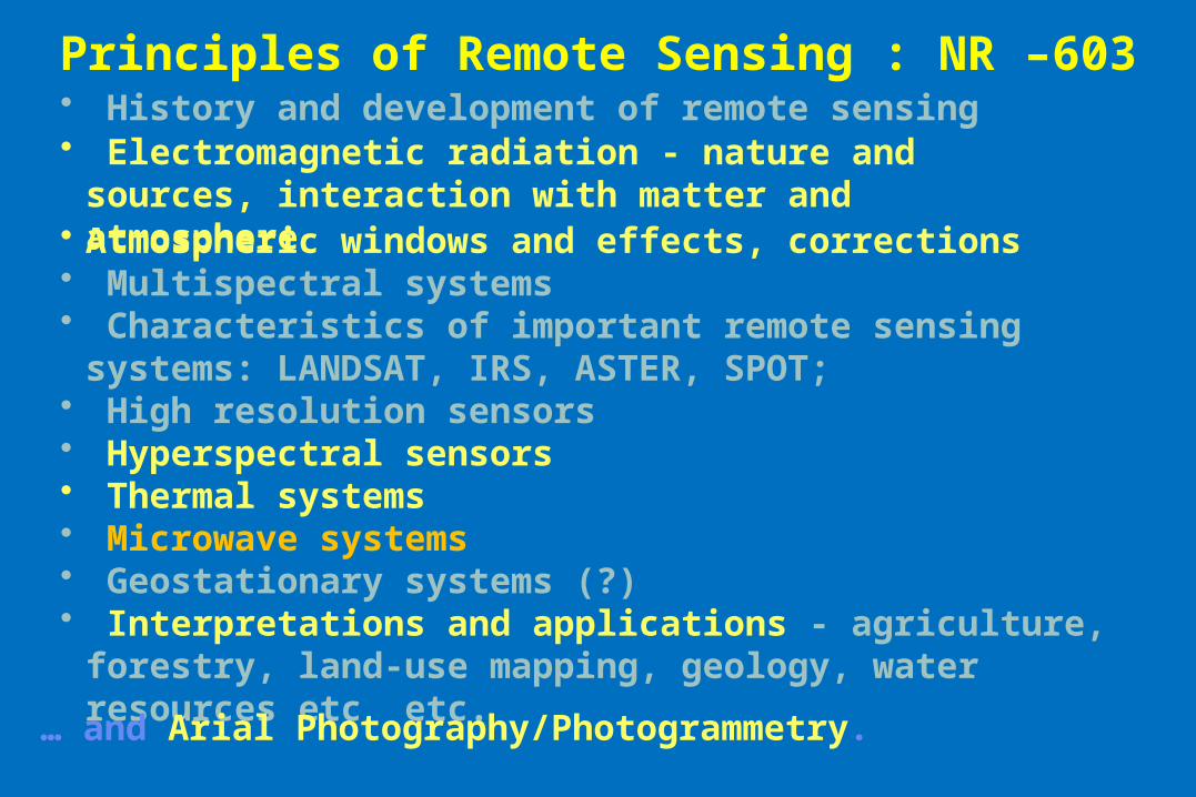
Principles of Remote Sensing : NR –603
• Atmospheric windows and effects, corrections• Multispectral systems• Characteristics of important remote sensing systems: LANDSAT, IRS,
ASTER, SPOT; • High resolution sensors• Hyperspectral sensors• Thermal systems• Microwave systems• Geostationary systems (?)• Interpretations and applications - agriculture, forestry, land-use
mapping, geology, water resources etc etc.
• History and development of remote sensing• Electromagnetic radiation - nature and sources, interaction
with matter and atmosphere
… and Arial Photography/Photogrammetry.