Embed Size (px)
Citation preview

Flight Planning
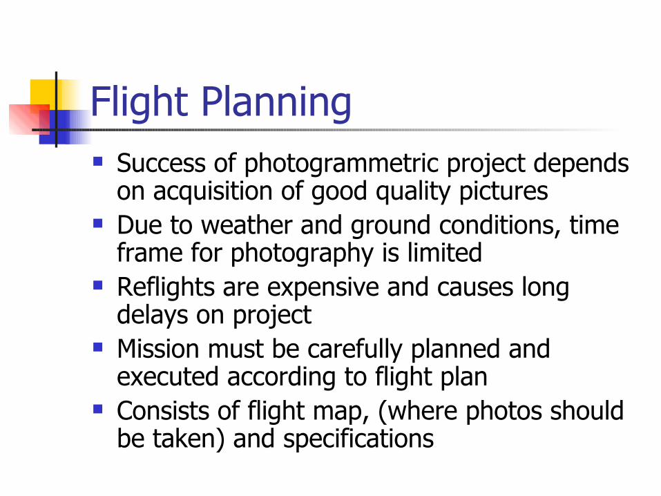
Flight Planning Success of photogrammetric project depends
on acquisition of good quality pictures Due to weather and ground conditions, time
frame for photography is limited Reflights are expensive and causes long
delays on project Mission must be carefully planned and
executed according to flight plan Consists of flight map, (where photos should
be taken) and specifications
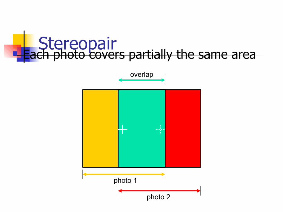
Stereopair Each photo covers partially the same area
overlap
photo 1
photo 2
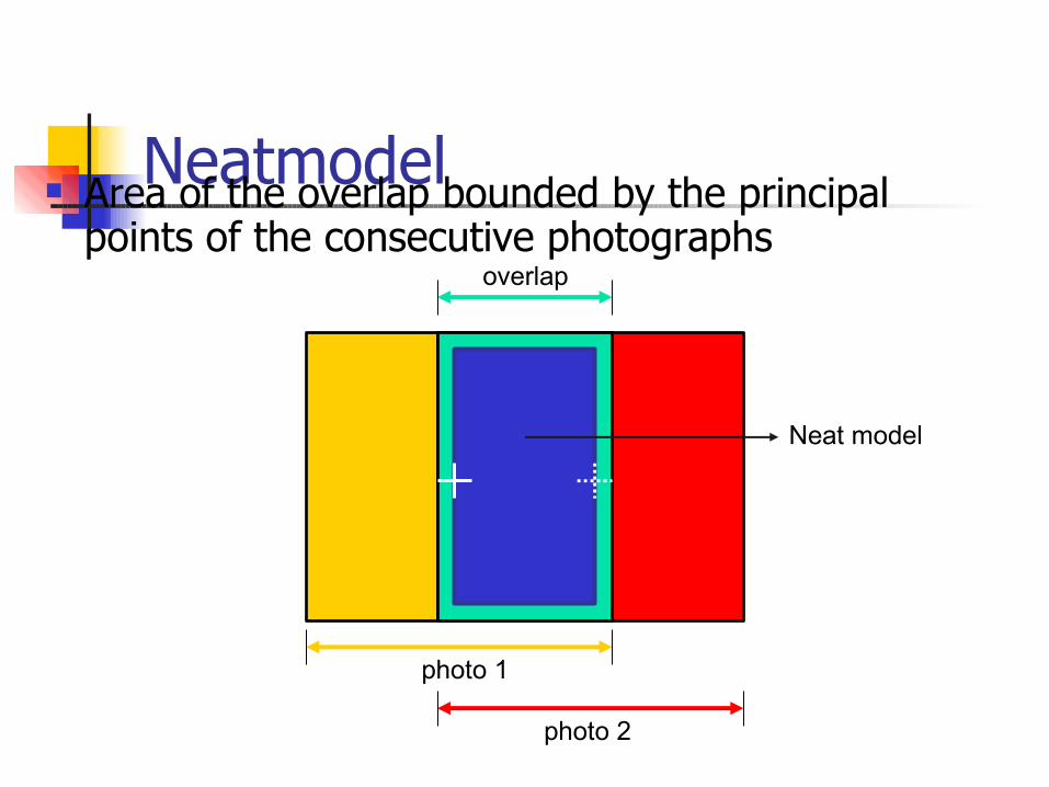
Neatmodel Area of the overlap bounded by the principal
points of the consecutive photographsoverlap
photo 1
photo 2
Neat model
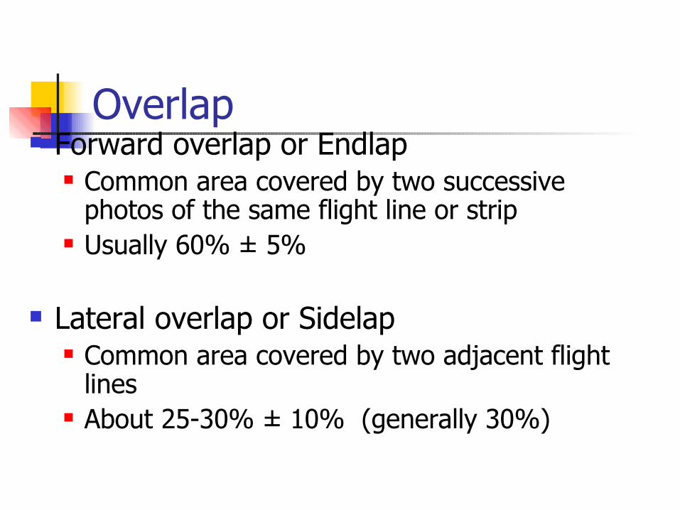
Overlap Forward overlap or Endlap
Common area covered by two successive photos of the same flight line or strip
Usually 60% ± 5%
Lateral overlap or Sidelap Common area covered by two adjacent flight
lines About 25-30% ± 10% (generally 30%)
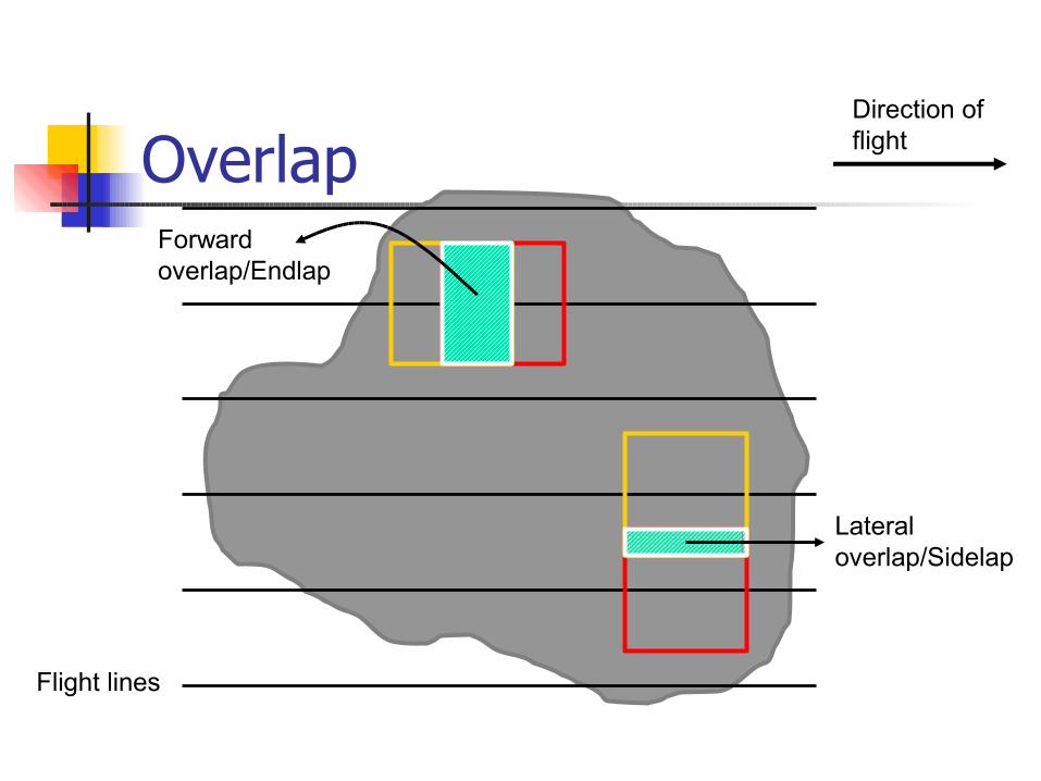
OverlapDirection of flight
Forward overlap/Endlap
Lateral overlap/Sidelap
Flight lines
Flight Plan What the aircrew has to do as indicated
by flight lines The design of aerial photography flight
in order to obtain desired photos at a certain scale, i.e., how the air crew will fly (where to put the flight lines, how high, etc.)
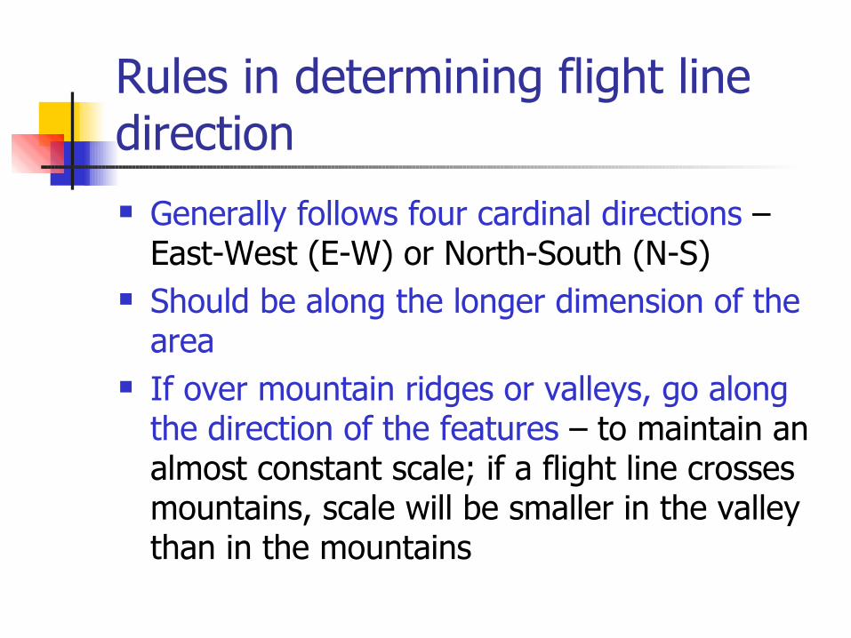
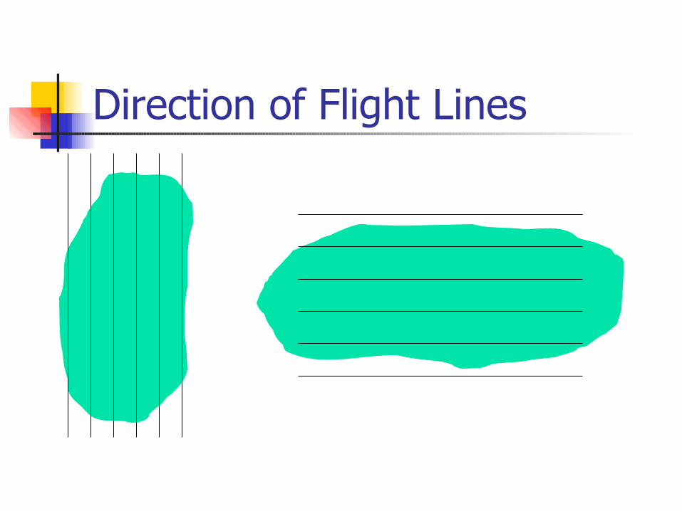
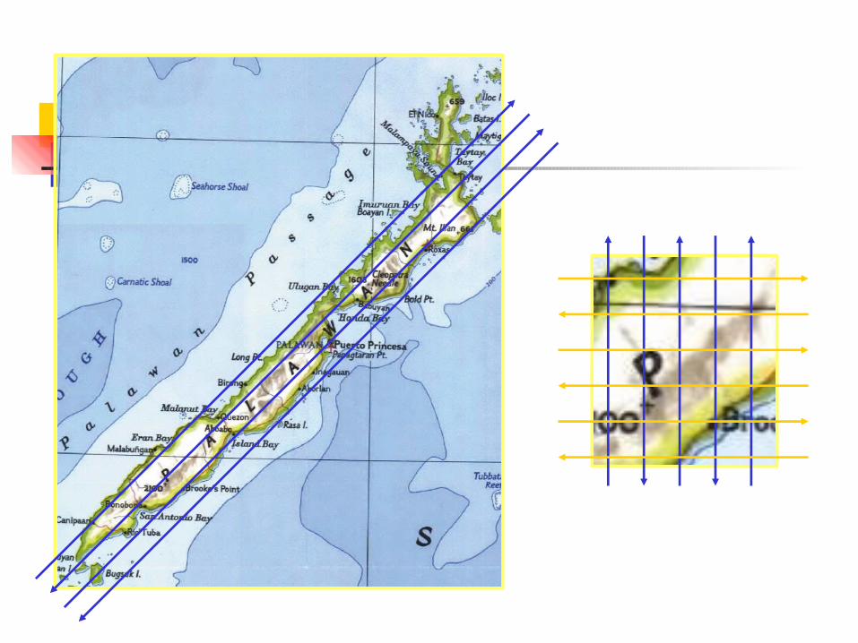
Rules in determining flight line direction Generally follows four cardinal directions –
East-West (E-W) or North-South (N-S) Should be along the longer dimension of the
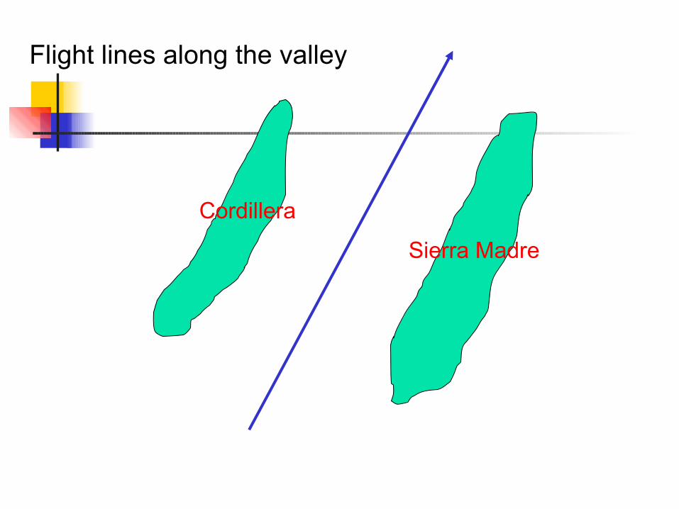
area If over mountain ridges or valleys, go along
the direction of the features – to maintain an almost constant scale; if a flight line crosses mountains, scale will be smaller in the valley than in the mountains
Direction of Flight Lines
Cordillera
Sierra Madre
Flight lines along the valley
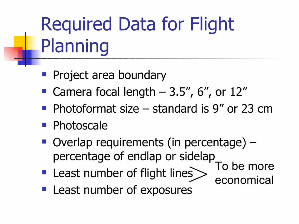
Required Data for Flight Planning Project area boundary Camera focal length – 3.5”, 6”, or 12” Photoformat size – standard is 9” or 23 cm Photoscale Overlap requirements (in percentage) –
percentage of endlap or sidelap Least number of flight lines Least number of exposures
To be more economical
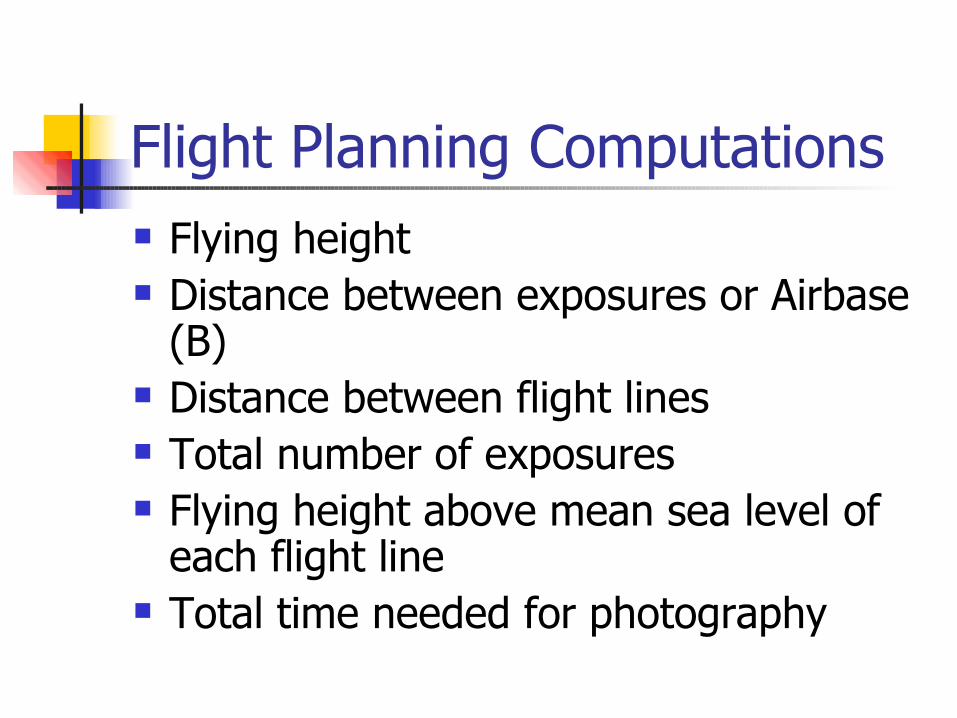
Flight Planning Computations Flying height Distance between exposures or Airbase
(B) Distance between flight lines Total number of exposures Flying height above mean sea level of
each flight line Total time needed for photography
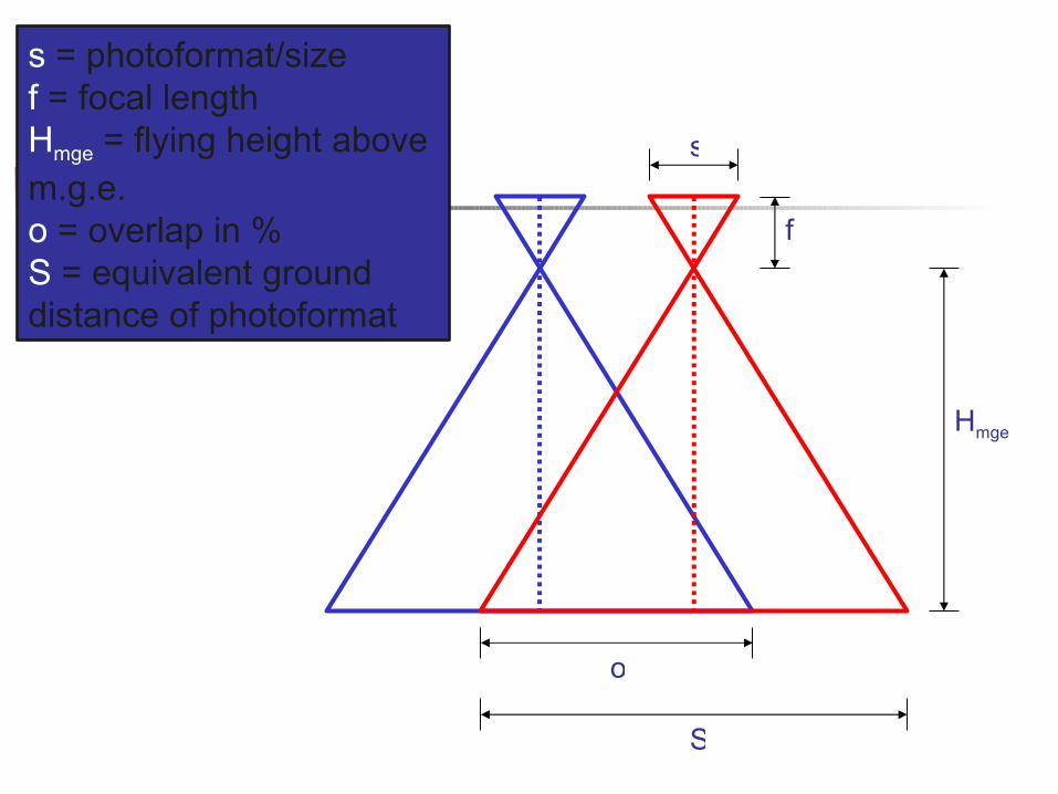
s
f
Hmge
S
o
s = photoformat/sizef = focal lengthHmge = flying height above m.g.e.o = overlap in %S = equivalent ground distance of photoformat
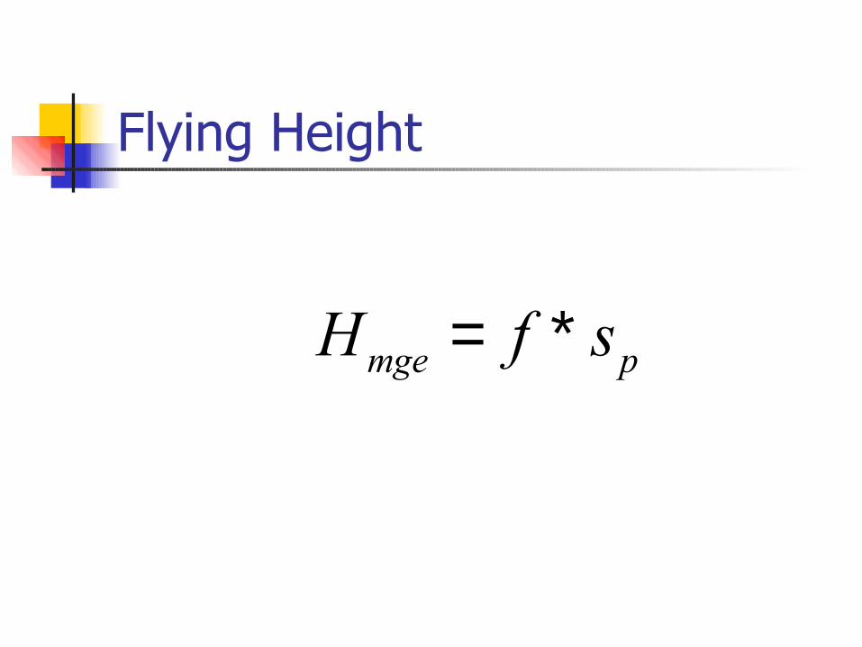
Flying Height
mge pH f s= ∗
Distance Between Exposures
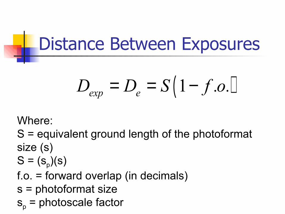
( )1exp eD D S f .o.= = −
Where:S = equivalent ground length of the photoformat size (s)S = (sp)(s)f.o. = forward overlap (in decimals)s = photoformat sizesp = photoscale factor
Distance Between Exposures
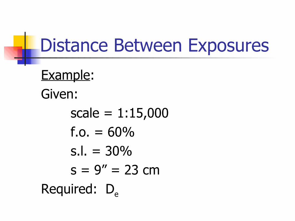
Example: Given:
scale = 1:15,000f.o. = 60%s.l. = 30%s = 9” = 23 cm
Required: De
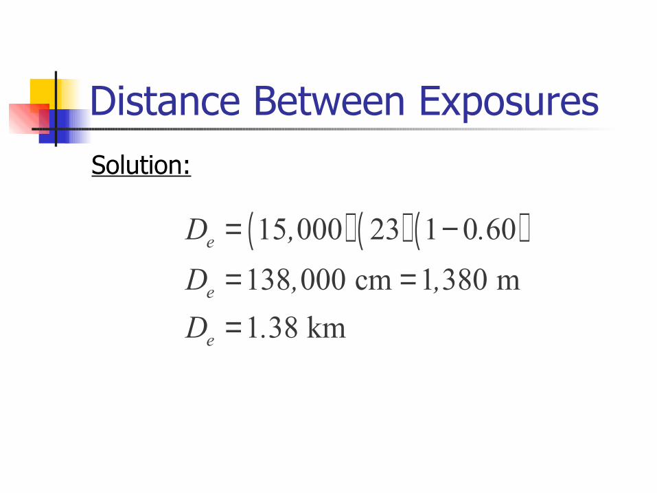
Distance Between ExposuresSolution:
( ) ( ) ( )15 000 23 1 0 60138 000 cm 1 380 m1 38 km
e
e
e
D , .D , ,D .
= −= ==
Distance Between Flight Lines
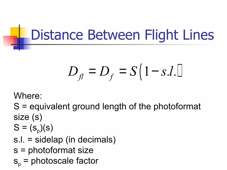
( )1fl fD D S s.l.= = −
Where:S = equivalent ground length of the photoformat size (s)S = (sp)(s)s.l. = sidelap (in decimals)s = photoformat sizesp = photoscale factor

Distance Between Exposures
Example: Given:
scale = 1:15,000f.o. = 60%s.l. = 30%s = 9” = 23 cm
Required: Df
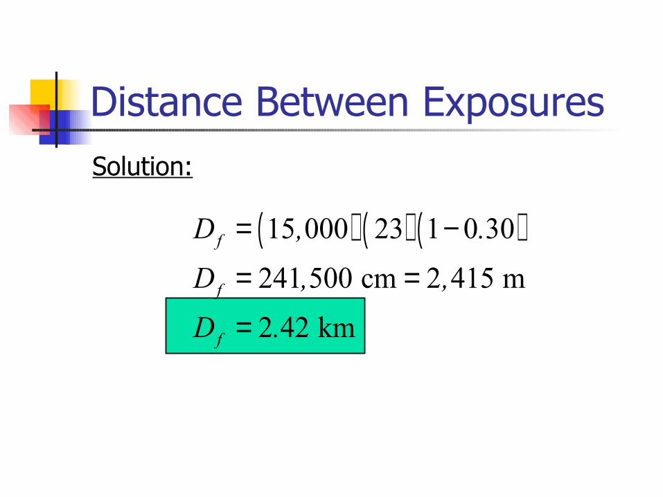
Distance Between ExposuresSolution:
( ) ( ) ( )15 000 23 1 0 30
241 500 cm 2 415 m
2 42 km
f
f
f
D , .D , ,D .
= −
= =
=
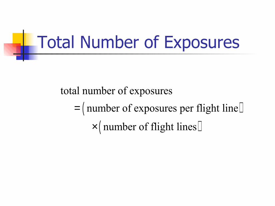
Total Number of Exposures
( )( )
total number of exposures number of exposures per flight line
number of flight lines
=
×
Total Number of Exposures
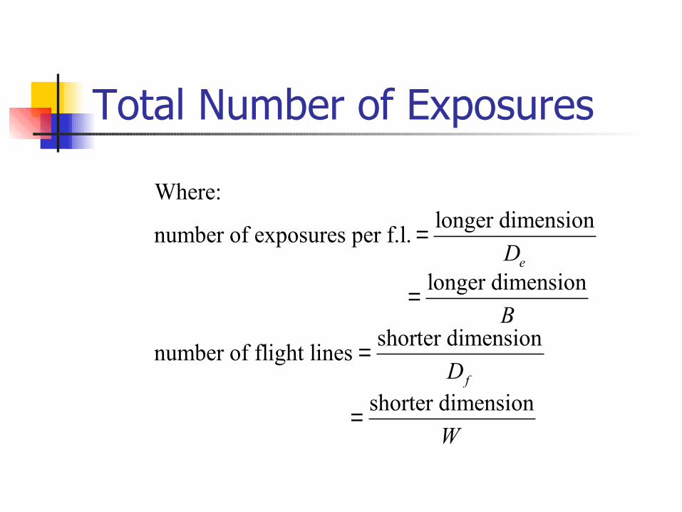
Where:longer dimensionnumber of exposures per f.l.
longer dimension
shorter dimensionnumber of flight lines
shorter di
e
f
D
B
D
=
=
=
= mensionW
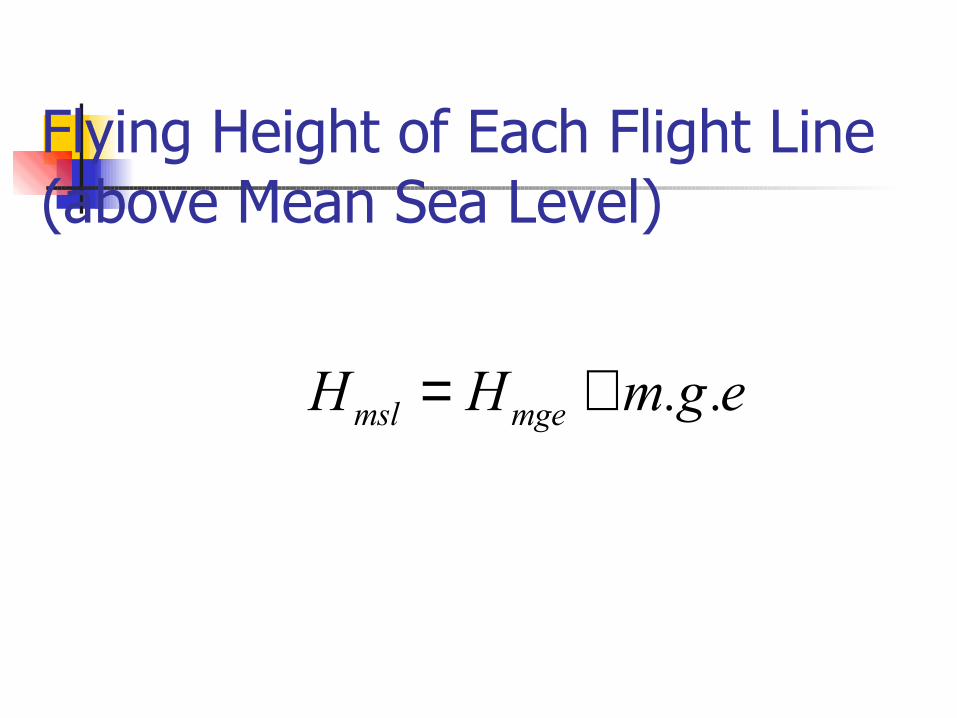
Flying Height of Each Flight Line(above Mean Sea Level)
msl mgeH H m.g.e= +
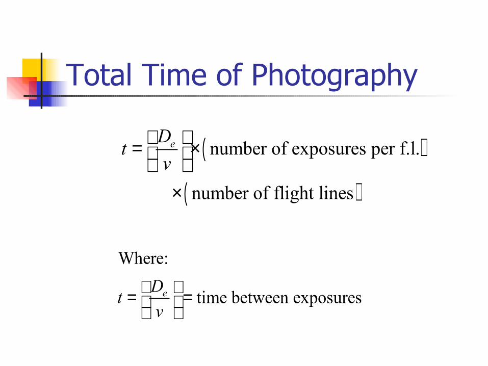
Total Time of Photography
( )
( )
number of exposures per f.l.
number of flight lines
eDtv
= × ×
Where:
time between exposureseDtv
= =
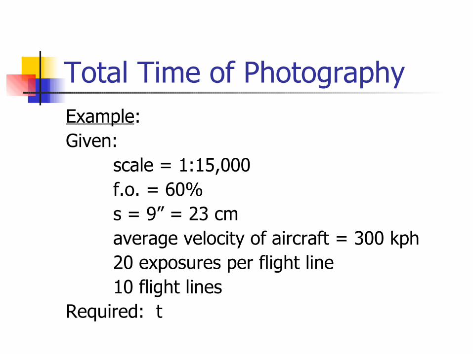
Total Time of PhotographyExample: Given:
scale = 1:15,000f.o. = 60%s = 9” = 23 cmaverage velocity of aircraft = 300 kph20 exposures per flight line10 flight lines
Required: t
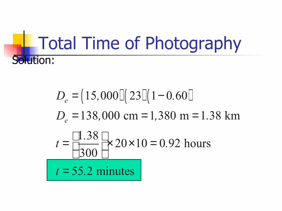
Total Time of PhotographySolution:
( ) ( ) ( )15 000 23 1 0 60138 000 cm 1 380 m 1 38 km1 38 20 10 0 92 hours300
55 2 minutes
e
e
D , .D , , .
.t .
t .
= −= = =
= × × = =