Embed Size (px)
Citation preview
PHOTOGRAMMETRIC RECONSTRUCTION AND 3D VISUALISATION OFBET GIORGIS, A ROCK-HEWN CHURCH IN ETHIOPIA
Thomas Buehrer & Zhang Li & Armin GruenInstitute of Geodesy & Photogrammetry, ETH Zurich, Switzerland
E-mail: [email protected] & [email protected] & [email protected]
Clive FraserDept. of Geomatics, University of Melbourne, Australia
E-mail: [email protected]
Heinz RutherDept. of Geomatics, University of Cape Town, South Africa
E-mail: [email protected]
KEY WORDS: heritage recording, Lalibela rock churches, photogrammetric reconstruction, visually realistic model, texturemapping
ABSTRACTAround 1200 AD, a number of remarkable rock churches were constructed in Lalibela, a town in northern Ethiopia. One constructionmanner stands apart in its uniqueness. This is the rock-hewn monolithic church, which while imitating a built-up structure is actuallycut in one piece from the rock and separated from it by an all-around trench. The best known of the monolithic churches is BetGiorgis (St George’s Church), a UNESCO World Heritage site. The narrowness of the trench around the church makes thephotogrammetric image recording demanding. Numerous photographs were necessary for a sufficient coverage. In a first phase of the3D model generation only monoscopic image measurement was carried out. First results were not satisfactory due to problems inproperly defining homologous points in the respective images. Such an ancient building suffers from erosion damages and hencelacks sharp corners and edges. Additional helpful construction features such as parallelism, perpendicularity and planarity can barelybe exploited as the building is relatively irregular. For these reasons additional measurements are performed in stereophotogrammetric mode. Still, there is a high demand of visual interpretation and manual measurements are absolutely necessary forproducing a comprehensive 3D model. For the 3D model rendering, the ETH-developed visualisation software Disp3D, whichemploys a view-dependent texture mapping procedure, has been used. The project, which is ongoing, will ultimately result in theproduction of a fine-detail visually realistic digital model of the church and its immediate surroundings.
1 THE ROCK CHURCHES OF LALIBELA
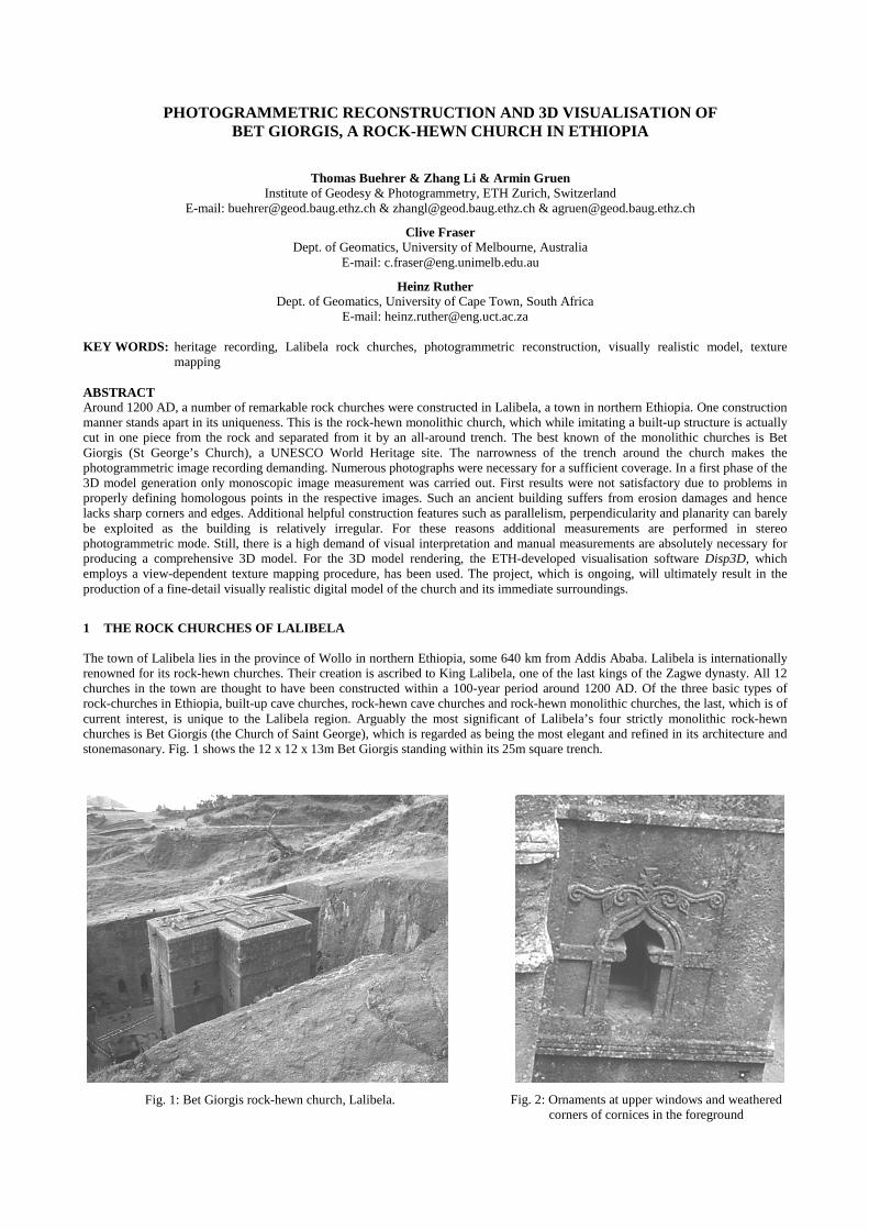
The town of Lalibela lies in the province of Wollo in northern Ethiopia, some 640 km from Addis Ababa. Lalibela is internationallyrenowned for its rock-hewn churches. Their creation is ascribed to King Lalibela, one of the last kings of the Zagwe dynasty. All 12churches in the town are thought to have been constructed within a 100-year period around 1200 AD. Of the three basic types ofrock-churches in Ethiopia, built-up cave churches, rock-hewn cave churches and rock-hewn monolithic churches, the last, which is ofcurrent interest, is unique to the Lalibela region. Arguably the most significant of Lalibela’s four strictly monolithic rock-hewnchurches is Bet Giorgis (the Church of Saint George), which is regarded as being the most elegant and refined in its architecture andstonemasonary. Fig. 1 shows the 12 x 12 x 13m Bet Giorgis standing within its 25m square trench.
Fig. 1: Bet Giorgis rock-hewn church, Lalibela. Fig. 2: Ornaments at upper windows and weatheredcorners of cornices in the foreground
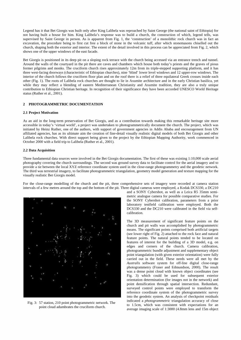
Legend has it that Bet Giorgis was built only after King Lalibela was reproached by Saint George (the national saint of Ethiopia) fornot having built a house for him. King Lalibela’s response was to build a church, the construction of which, legend tells, wassupervised by Saint George in person. As is apparent from Fig. 1, the ‘construction’ of a monolithic rock church was in fact anexcavation, the procedure being to first cut free a block of stone in the volcanic tuff, after which stonemasons chiselled out thechurch, shaping both the exterior and interior. The extent of the detail involved in this process can be appreciated from Fig. 2, whichshows one of the upper windows of the east facade.
Bet Giorgis is positioned in its deep pit on a sloping rock terrace with the church being accessed via an entrance trench and tunnel.Around the walls of the courtyard in the pit there are caves and chambers which house both today’s priests and the graves of piousformer pilgrims and monks. The cruciform church rises approximately 12m from its triple-stepped supporting platform, and it hasthree west-facing doorways (characteristic of Ethiopian churches), nine ‘blind’ lower level windows and 12 upper-row windows. Theinterior of the church follows the cruciform floor plan and on the roof there is a relief of three equilateral Greek crosses inside eachother (Fig. 1). The roots of Lalibela rock churches are thought to lie in Axumite architecture and in the early Christian basilica, yetwhile they may reflect a blending of eastern Mediterranean Christianity and Axumite tradition, they are also a truly uniquecontribution to Ethiopian Christian heritage. In recognition of their significance they have been accorded UNESCO World Heritagestatus (Ruther et al., 2001).
2 PHOTOGRAMMETRIC DOCUMENTATION
2.1 Project Motivation
As an aid in the long-term preservation of Bet Giorgis, and as a contribution towards making this remarkable heritage site moreaccessible in today’s ‘virtual world’, a project was undertaken to photogrammetrically document the church. The project, which wasinitiated by Heinz Ruther, one of the authors, with support of government agencies in Addis Ababa and encouragement from UNaffiliated agencies, has as its ultimate aim the creation of fine-detail visually realistic digital models of both Bet Giorgis and otherLalibela rock churches. With direct support being given to the project by the Ethiopian Mapping Authority, work commenced inOctober 2000 with a field trip to Lalibela (Ruther et al., 2001).
2.2 Data Acquisition
Three fundamental data sources were involved in the Bet Giorgis documentation. The first of these was existing 1:10,000 scale aerialphotography covering the church surroundings. The second was ground survey data to facilitate control for the aerial imagery and toprovide a tie between the local XYZ reference coordinate system used in the close-range photogrammetry and the geodetic network.The third was terrestrial imagery, to facilitate photogrammetric triangulation, geometry model generation and texture mapping for thevisually realistic Bet Giorgis model.
For the close-range modelling of the church and the pit, three comprehensive sets of imagery were recorded at camera stationintervals of a few metres around the top and the bottom of the pit. Three digital cameras were employed, a Kodak DCS330, a DC210
and a SONY Cybershot, as well as a Leica R5 35mm semi-metric analogue camera for possible comparative studies. Forthe SONY Cybershot calibration, parameters from a priorlaboratory testfield calibration were employed. Both theDCS330 and the DC210 were calibrated in the field via self-calibration.
The 3D measurement of significant feature points on thechurch and pit walls was accomplished by photogrammetricmeans. The significant points comprised both artificial targets(see lower right of Fig. 2) attached to the rock face and naturalfeature points. The natural points tended to be located onfeatures of interest for the building of a 3D model, e.g. onedges and corners of the church. Camera calibration,photogrammetric bundle adjustment and supplementary objectpoint triangulation (with given exterior orientation) were fullycarried out in the field. These needs were all met by theAustralis software system for off-line digital close-rangephotogrammetry (Fraser and Edmundson, 2000). The resultwas a dense point cloud with known object coordinates (seeFig. 3) which could be used for subsequent exteriororientation determination (for images not in the network) andpoint densification through spatial intersection. Redundant,surveyed control points were employed to transform thereference coordinate system of the photogrammetric surveyinto the geodetic system. An analysis of checkpoint residualsindicated a photogrammetric triangulation accuracy of closeto 1.5cm, which was consistent with expectations for anaverage imaging scale of 1:3000 (4.8mm lens and 15m object
Fig. 3: 57 station, 210 point photogrammetric network. Thepoint cloud adumbrates the cruciform church.
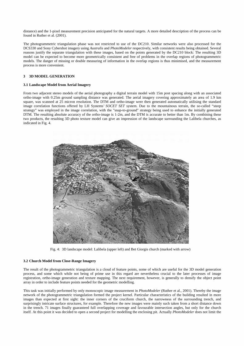
distance) and the 1-pixel measurement precision anticipated for the natural targets. A more detailed description of the process can befound in Ruther et al. (2001).
The photogrammetric triangulation phase was not restricted to use of the DC210. Similar networks were also processed for theDCS330 and Sony Cybershot imagery using Australis and PhotoModeler respectively, with consistent results being obtained. Severalreasons justify the separate triangulation with these images, based on the points generated by the DC210 block: The resulting 3Dmodel can be expected to become more geometrically consistent and free of problems in the overlap regions of photogrammetricmodels. The danger of missing or double measuring of information in the overlap regions is thus minimised, and the measurementprocess is more convenient.
3 3D MODEL GENERATION
3.1 Landscape Model from Aerial Imagery
From two adjacent stereo models of the aerial photography a digital terrain model with 15m post spacing along with an associatedortho-image with 0.25m ground sampling distance was generated. The aerial imagery covering approximately an area of 1.9 kmsquare, was scanned at 25 micron resolution. The DTM and ortho-image were then generated automatically utilising the standardimage correlation functions offered by LH Systems’ SOCET SET system. Due to the mountainous terrain, the so-called “steepstrategy” was employed in the image correlation, with the "snap-to-ground" strategy being used to enhance the initially generatedDTM. The resulting absolute accuracy of the ortho-image is 1-2m, and the DTM is accurate to better than 1m. By combining thesetwo products, the resulting 3D photo texture model can give an impression of the landscape surrounding the Lalibela churches, asindicated in Fig. 4.
3.2 Church Model from Close-Range Imagery
The result of the photogrammetric triangulation is a cloud of feature points, some of which are useful for the 3D model generationprocess, and some which while not being of prime use in this regard are nevertheless crucial to the later processes of imageregistration, ortho-image generation and texture mapping. The next requirement, however, is generally to densify the object pointarray in order to include feature points needed for the geometric modelling.
This task was initially performed by only monoscopic image measurement in PhotoModeler (Ruther et al., 2001). Thereby the imagenetwork of the photogrammetric triangulation formed the project kernel. Particular characteristics of the building resulted in moreimages than expected at first sight: the inner corners of the cruciform church, the narrowness of the surrounding trench, andsurprisingly intricate surface structures, for example. Therefore the new images were mainly such taken from a short distance downin the trench. 71 images finally guaranteed full overlapping coverage and favourable intersection angles, but only for the churchitself. At this point it was decided to open a second project for modelling the enclosing pit. Actually PhotoModeler does not limit the
Fig. 4: 3D landscape model: Lalibela (upper left) and Bet Giorgis church (marked with arrow)
number of project images, but a huge number makes the project handling rather complex for the user. For the pit project the networkof the photogrammetric triangulation was first reduced to 28 images, the minimal number still guaranteeing a stable network aroundthe church. New images were added stepwise till an overall number of 63 allowed a complete coverage of the walls and bottom of thepit. Again, this is a very large number of images but one has to recall that most wall images ’suffer’ from occlusions in the foregroundcaused by the church itself. However, as most control points are located on the church itself, the images covering parts of it serve as akind of ‘support pillars’ for the photogrammetric triangulation of some pure wall images in between.
It is noteworthy that in both projects every new feature point was also included in the bundle adjustment such that the strength of thenetwork improved in a stepwise fashion with the collection of 3D model points. The number of points in the church model currentlyis about 1600. The work with PhotoModeler was not limited to point measurements alone. Regarding the 3D wireframe/texturemodel all connecting lines and triangle faces were also defined. Both operations had to be carried out manually.
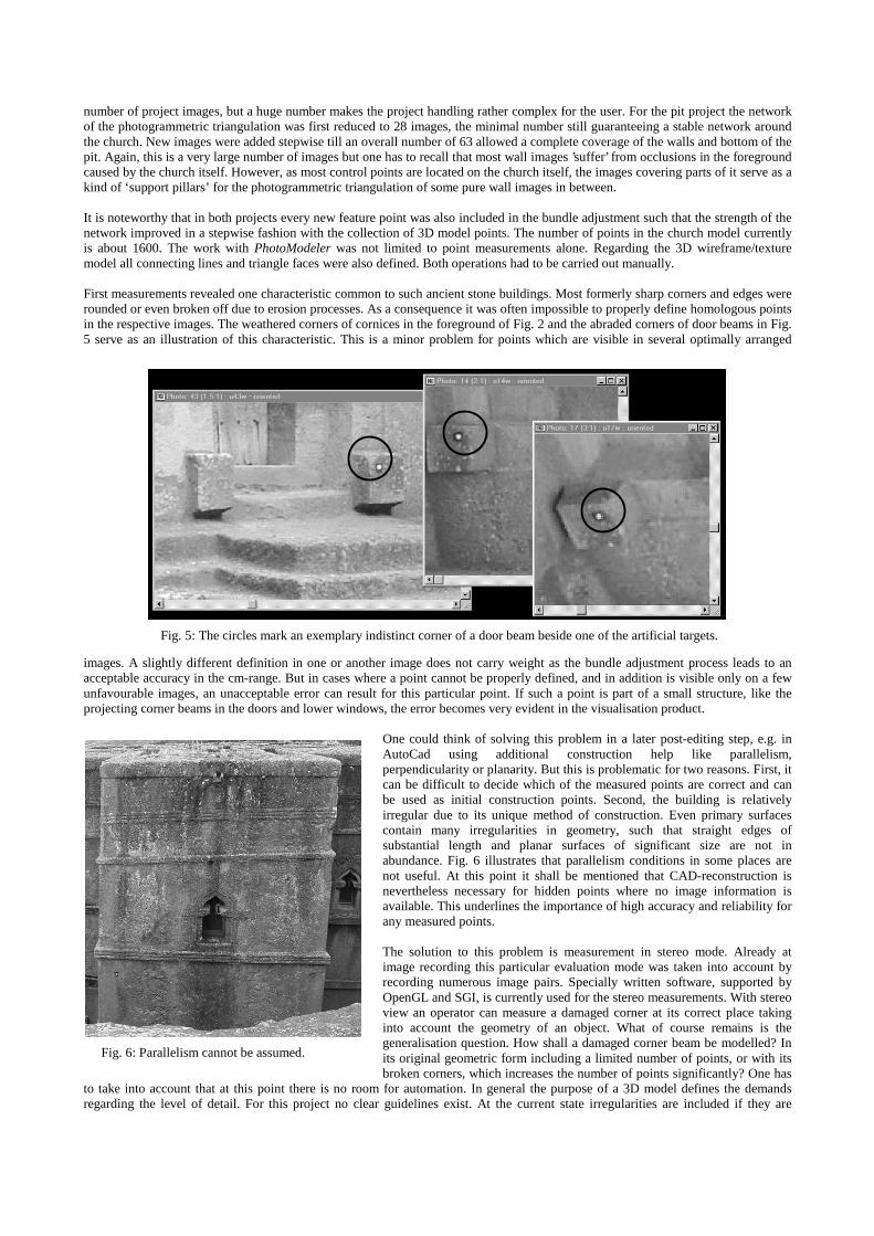
First measurements revealed one characteristic common to such ancient stone buildings. Most formerly sharp corners and edges wererounded or even broken off due to erosion processes. As a consequence it was often impossible to properly define homologous pointsin the respective images. The weathered corners of cornices in the foreground of Fig. 2 and the abraded corners of door beams in Fig.5 serve as an illustration of this characteristic. This is a minor problem for points which are visible in several optimally arranged
images. A slightly different definition in one or another image does not carry weight as the bundle adjustment process leads to anacceptable accuracy in the cm-range. But in cases where a point cannot be properly defined, and in addition is visible only on a fewunfavourable images, an unacceptable error can result for this particular point. If such a point is part of a small structure, like theprojecting corner beams in the doors and lower windows, the error becomes very evident in the visualisation product.
One could think of solving this problem in a later post-editing step, e.g. inAutoCad using additional construction help like parallelism,perpendicularity or planarity. But this is problematic for two reasons. First, itcan be difficult to decide which of the measured points are correct and canbe used as initial construction points. Second, the building is relativelyirregular due to its unique method of construction. Even primary surfacescontain many irregularities in geometry, such that straight edges ofsubstantial length and planar surfaces of significant size are not inabundance. Fig. 6 illustrates that parallelism conditions in some places arenot useful. At this point it shall be mentioned that CAD-reconstruction isnevertheless necessary for hidden points where no image information isavailable. This underlines the importance of high accuracy and reliability forany measured points.
The solution to this problem is measurement in stereo mode. Already atimage recording this particular evaluation mode was taken into account byrecording numerous image pairs. Specially written software, supported byOpenGL and SGI, is currently used for the stereo measurements. With stereoview an operator can measure a damaged corner at its correct place takinginto account the geometry of an object. What of course remains is thegeneralisation question. How shall a damaged corner beam be modelled? Inits original geometric form including a limited number of points, or with itsbroken corners, which increases the number of points significantly? One has
to take into account that at this point there is no room for automation. In general the purpose of a 3D model defines the demandsregarding the level of detail. For this project no clear guidelines exist. At the current state irregularities are included if they are
Fig. 6: Parallelism cannot be assumed.
Fig. 5: The circles mark an exemplary indistinct corner of a door beam beside one of the artificial targets.
connected to the unique method of construction, and erosion-damaged areas are only visualised with photo texture. In spite of thisrestriction, a comprehensive CAD model over the whole church area has been constructed, but will be updated in the near future.
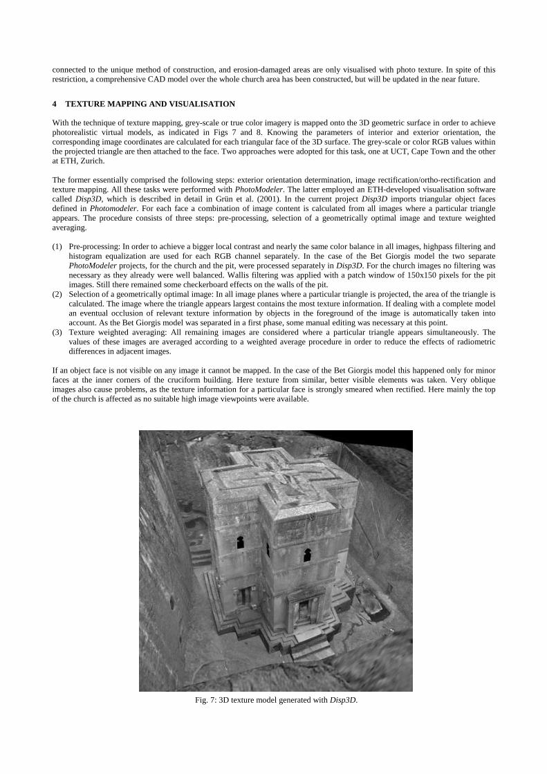
4 TEXTURE MAPPING AND VISUALISATION
With the technique of texture mapping, grey-scale or true color imagery is mapped onto the 3D geometric surface in order to achievephotorealistic virtual models, as indicated in Figs 7 and 8. Knowing the parameters of interior and exterior orientation, thecorresponding image coordinates are calculated for each triangular face of the 3D surface. The grey-scale or color RGB values withinthe projected triangle are then attached to the face. Two approaches were adopted for this task, one at UCT, Cape Town and the otherat ETH, Zurich.
The former essentially comprised the following steps: exterior orientation determination, image rectification/ortho-rectification andtexture mapping. All these tasks were performed with PhotoModeler. The latter employed an ETH-developed visualisation softwarecalled Disp3D, which is described in detail in Grün et al. (2001). In the current project Disp3D imports triangular object facesdefined in Photomodeler. For each face a combination of image content is calculated from all images where a particular triangleappears. The procedure consists of three steps: pre-processing, selection of a geometrically optimal image and texture weightedaveraging.
(1) Pre-processing: In order to achieve a bigger local contrast and nearly the same color balance in all images, highpass filtering andhistogram equalization are used for each RGB channel separately. In the case of the Bet Giorgis model the two separatePhotoModeler projects, for the church and the pit, were processed separately in Disp3D. For the church images no filtering wasnecessary as they already were well balanced. Wallis filtering was applied with a patch window of 150x150 pixels for the pitimages. Still there remained some checkerboard effects on the walls of the pit.
(2) Selection of a geometrically optimal image: In all image planes where a particular triangle is projected, the area of the triangle iscalculated. The image where the triangle appears largest contains the most texture information. If dealing with a complete modelan eventual occlusion of relevant texture information by objects in the foreground of the image is automatically taken intoaccount. As the Bet Giorgis model was separated in a first phase, some manual editing was necessary at this point.
(3) Texture weighted averaging: All remaining images are considered where a particular triangle appears simultaneously. Thevalues of these images are averaged according to a weighted average procedure in order to reduce the effects of radiometricdifferences in adjacent images.
If an object face is not visible on any image it cannot be mapped. In the case of the Bet Giorgis model this happened only for minorfaces at the inner corners of the cruciform building. Here texture from similar, better visible elements was taken. Very obliqueimages also cause problems, as the texture information for a particular face is strongly smeared when rectified. Here mainly the topof the church is affected as no suitable high image viewpoints were available.
Fig. 7: 3D texture model generated with Disp3D.
Another disturbing effect arises from the subdivision of the model into triangular faces. Depending on the illumination of the 3Dmodel, the single faces become visible even when having only small differences in inclination. The solution of dissecting nearlyplanar faces in as few triangles possible would help but fails in the case of adjacent detailed structures. In addition, irregularities inthe planar faces would eventually be lost. Another solution would be a segmentation into even more small and approximatelyequilateral triangles, which would model all discontinuities properly and at the same time reduce the disturbing effects caused byillumination of the 3D model. Without automation this process would be an immense task. Disp3D already includes basic automationfunctionality such as image matching tools; indeed these still have to be adapted for the task of building modelling.
Disp3D delivers the following visualisation functions: point cloud; wireframe with hidden lines; shaded surface; and texture map inmono and stereo display, via anaglyph projection and polarized stereo. Image streams for MPEG-1/MPEG-2 videos can also becreated. The final textured model can be viewed with Disp3D or it can be converted to VRML2 for viewing with standardvisualization packages. Our model will also be made available on the Web at a later date.
5 CONCLUSIONS
Ruther et al. (2001) refer to a changing paradigm in the photogrammetric recording and documentation of cultural heritage sites, atopic also discussed in Patias & Peipe (2000). Recent enhancements of the photogrammetric approaches are highlighted and amongthese is a trend away from stereo models to multi-image surface reconstruction. During the photogrammetric reconstruction of BetGiorgis church it became obvious that stereo measurements still are of considerable importance in building a high quality model tofine detail and resolution. Our experience does not challenge the fact that in most situations multi-image techniques in mono modeare more appropriate. Instead, it simply illustrates that stereo still has much to offer as a complementary technique, especially incases where a good framework of ‘control’ has been build via the monoscopic photogrammetric process and where 3D visualinterpretation is necessary for feature definition.
Digital still video cameras have proven to be a very appropriate device for such kind of work. Fast image recording and storage,sufficient accuracy performance, together with the ease of use makes them an excellent choice, especially for this exploration-type ofproject. However, if high quality texture mapping is required one should pay much more attention to illumination conditions and tothe geometric relations between image planes and major object faces. This is a significant change in recording concepts, compared tothe traditional approach, which was based on wireframe model optimisation and minimisation of the number of images. Denserimage sequences will solve some of these problems and also simplify any automated or semi-automated processing tasks.The conduct of the Bet Giorgis documentation is otherwise very much in accordance with the new paradigm referred to above, and itis the hope of the authors that once the visually realistic digital modelling of this church and others in Lalibela are complete, avaluable information source will have been generated for use in site conservation, historical and architectural studies, educationrelated to Ethiopia’s rich heritage and history, and in visualisation for general enquiry and tourism.
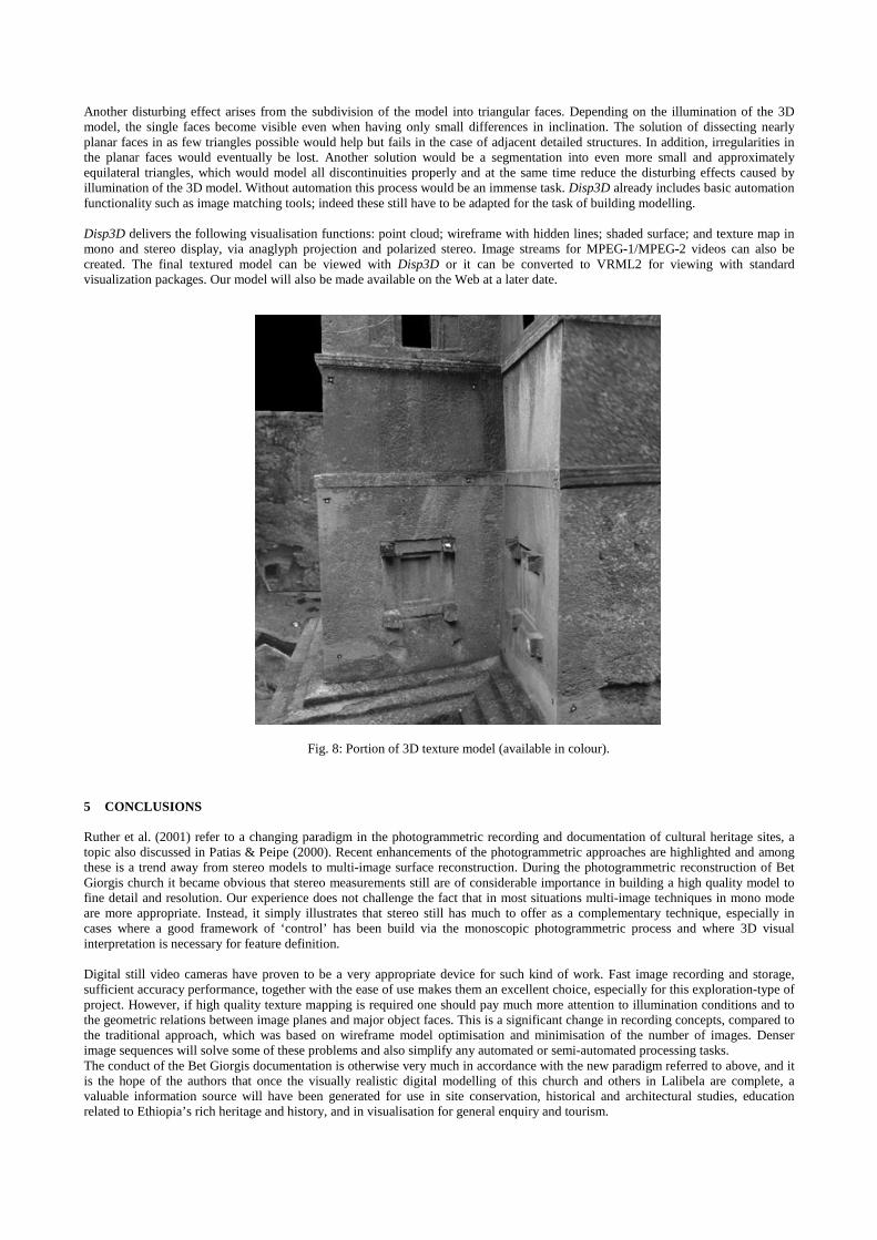
Fig. 8: Portion of 3D texture model (available in colour).

6 ACKNOWLEDGEMENTS
The authors gratefully acknowledge the support and assistance of the Ethiopian Mapping Authority in the conduct of the LalibelaProject. The assistance of Mr Hadgu Medhin and the encouragement of Mr Tsegaye Denboba Wolde from the EMA have been muchappreciated. The authors also acknowledge assistance given in the fieldwork and data processing stages by M.C. Biers and AlemuNebebe.
REFERENCES
Fraser, C.S. & Edmundson, K.L., 2000. Design and Implementation of a Computational Processing System for Off-Line DigitalClose-Range Photogrammetry. ISPRS Int. Journal of Photogrammetry & Remote Sensing, 55(2): 94-104.
Grün, A., Zhang, L. and Visnovcova, J., 2001. Automatic Reconstruction and Visualization of a Complex Buddha Tower of Bayon,Angkor, Cambodia. Proceedings, 21. Wissenschaftlich-Technische Jahrestagung der Deutschen Gesellschaft für Photogrammetrieund Fernerkundung, Konstanz, Germany, 4 - 6 Sep.
Patias, P. & Peipe, J., 2000. Photogrammery and CAD/CAM in culture and industry – an ever changing paradigm. Int. Archives ofPhotogrammetry & Remote Sensing, Amsterdam, Vol. 33, Part B5, 599-603.
Ruther, H., Fraser, C., Gruen, A. & Buehrer, T., 2001. The recording of Bet Giorgis, a 12th century rock-hewn church in Ethiopia.Proceedings, International Workshop on Recreating the Past, Ayutthaya, Thailand, 26 Feb. – 3 Mar.